

Page 1

DGP000814AAA
Issue: 2-01
July 2007
GSS6100 AND SIMCHAN USER MANUAL
THE INFORMATION CONTAINED IN THIS DOCUMENT IS THE PROPERTY OF SPIRENT
COMMUNICATIONS PLC. EXCEPT AS SPECIFICALLY AUTHORISED IN WRITING BY SPIRENT
SPIRENT COMMUNICATIONS PLC, THE HOLDER OF THIS DOCUMENT SHALL KEEP ALL
INFORMATION CONTAINED HEREIN CONFIDENTIAL AND SHALL PROTECT SAME IN WHOLE OR IN
PART FROM DISCLOSURE AND DISSEMINATION TO ALL THIRD PARTIES TO THE SAME DEGREE IT
PROTECTS ITS OWN CONFIDENTIAL INFORMATION.
© SPIRENT COMMUNICATIONS PLC 2005-2007
PROPRIETARY INFORMATION
Page 2

Page 3

2-01 DGP000814AAA
About this publication
Purpose
This document provides all information for installing and using SimCHAN
software on a Windows XP PC.
This document provides all information for the installation and operation of
the GSS6100 signal generator using both SimCHAN software and the
remote command set.
Audience
This document is intended for all users of the GSS6100 signal generator and
SimCHAN software.
In this document:
References to Spirent refer to Spirent Communications - Performance
Analysis & Wireless Positioning (Spirent Communications PA-WP), unless
otherwise stated.
GPS is used as a generic term for any of the satellite navigation systems
supported by the Spirent range of Satellite Navigation Simulator products.
A specific satellite navigation system is referred to by its name.
GSS6100 and SimCHAN user manual
© Spirent Communications Plc 2005 - 2007
About
Page 4

Page 5

2-01 DGP000814AAA
CONTENTS
ABOUT THIS PUBLICATION.................................................................................................................I
CHAPTER 1: GENERAL ......................................................................................................................1-1
1.1 RECORD OF ISSUE 1-1
1.2 REFERENCED DOCUMENTS 1-2
1.3 DELIVERABLES 1-2
1.4 COPYRIGHT NOTICES 1-2
1.5 ACRONYMS AND ABBREVIATIONS 1-3
1.5.1 Document conventions ................................................................................... 1-5
CHAPTER 2: INTRODUCTION..........................................................................................................2-1
2.1 SIMCHAN OR REMOTE OPERATION 2-1
CHAPTER 3: HARDWARE OVERVIEW AND INSTALLATION ................................................3-1
3.1 FRONT PANEL 3-1
3.2 REAR PANEL 3-1
3.3 INSTALLATION AND CONNECTION TO HOST PC 3-4
CHAPTER 4: PRINCIPLES OF OPERATION .................................................................................4-1
4.1 OVERVIEW 4-1
4.2 SIMCHAN INTERFACE 4-2
4.2.1 Controlling the GSS6100 ................................................................................4-3
4.2.2 Help................................................................................................................4-3
4.2.3 Status bar .......................................................................................................4-3
CHAPTER 5: GSS6100 OPERATING DETAILS ..............................................................................5-1
5.1 SIMCHAN TOOLBAR 5-2
5.1.1 ARM the GSS6100 .........................................................................................5-2
5.1.2 RUN the GSS6100 .........................................................................................5-3
5.1.3 HALT the GSS6100........................................................................................ 5-3
5.2 SIMCHAN MAIN AREA 5-4
5.2.1 Pseudo Range Velocity ..................................................................................5-5
5.2.2 Velocity profiles ..............................................................................................5-6
5.2.3 RF Power .....................................................................................................5-11
5.2.4 Simulation Time............................................................................................ 5-12
5.2.5 Nav Data Message.......................................................................................5-13
5.2.6 PRN.............................................................................................................. 5-14
5.2.7 SBAS Message Rate.................................................................................... 5-16
5.2.8 Pseudo Range.............................................................................................. 5-16
5.2.9 Time into Run ...............................................................................................5-17
5.2.10 Prompts, Warnings and Errors......................................................................5-17
5.3 NAVIGATION DATA TEMPLATE 5-18
5.4 AUTOGO 5-20
5.4.1 Limitations of AutoGO...................................................................................5-21
5.5 HARDWARE OPTIONS AND SETTINGS 5-22
GSS6100 and SimCHAN user manual
© Spirent Communications Plc 2005 - 2007
Contents
i
Page 6

DGP000814AAA 2-01
5.6 SYNCHRONISATION 5-26
5.6.1 1PPS IN........................................................................................................ 5-27
5.6.2 TRIG IN – Immediate Mode..........................................................................5-27
5.6.3 TRIG IN – Delayed Mode..............................................................................5-28
CHAPTER 6: REMOTE INTERFACE ...............................................................................................6-1
6.1 INTERFACE TYPES 6-1
6.1.1 GPIB...............................................................................................................6-1
6.1.2 RS232.............................................................................................................6-1
6.2 COMMAND SET 6-2
6.2.1 Notes on the syntax definition.........................................................................6-2
6.2.2 *IDN?.............................................................................................................. 6-3
6.2.3 ARMS .............................................................................................................6-3
6.2.4 BITE................................................................................................................6-4
6.2.5 COSW ............................................................................................................6-4
6.2.6 EREF..............................................................................................................6-5
6.2.7 EREF ?...........................................................................................................6-5
6.2.8 GPIB...............................................................................................................6-5
6.2.9 HALT ..............................................................................................................6-6
6.2.10 IDEN...............................................................................................................6-6
6.2.11 IPRG...............................................................................................................6-6
6.2.12 LEVL............................................................................................................... 6-7
6.2.13 LEVL ?............................................................................................................ 6-7
6.2.14 MODE.............................................................................................................6-8
6.2.15 MODE ?..........................................................................................................6-8
6.2.16 NDSW.............................................................................................................6-9
6.2.17 NMOD.............................................................................................................6-9
6.2.18 NSAV............................................................................................................ 6-12
6.2.19 NSAV ?......................................................................................................... 6-13
6.2.20 NSEL ............................................................................................................6-13
6.2.21 PFIL.............................................................................................................. 6-14
6.2.22 PROF............................................................................................................6-14
6.2.23 PROS ...........................................................................................................6-15
6.2.24 PRTY............................................................................................................6-15
6.2.25 RSET............................................................................................................6-16
6.2.26 RUNS ...........................................................................................................6-16
6.2.27 SERR............................................................................................................6-17
6.2.28 G2D ..............................................................................................................6-17
6.2.29 SIGT .............................................................................................................6-18
6.2.30 SNUM ?........................................................................................................6-18
6.2.31 STAT ............................................................................................................6-18
6.2.32 SVID .............................................................................................................6-19
6.2.33 TIOP .............................................................................................................6-19
6.2.34 TIOP ? ..........................................................................................................6-20
6.2.35 TRIG............................................................................................................. 6-20
6.2.36 VCTY............................................................................................................6-21
ii
Contents
GSS6100 and SimCHAN user manual
© Spirent Communications Plc 2005 - 2007
Page 7

2-01 DGP000814AAA
6.2.37 WEEK........................................................................................................... 6-21
6.2.38 WRTE........................................................................................................... 6-22
6.2.39 ZCNT............................................................................................................ 6-22
6.3 COMMAND AVAILABILITY BY MODE 6-22
6.4 SERIAL POLL – STATUS BITS 6-24
6.5 EXAMPLE COMMAND SEQUENCES 6-24
6.5.1 Example GPS operations..............................................................................6-24
6.5.2 Example with external trigger........................................................................6-26
6.5.3 Example with external signals.......................................................................6-27
CHAPTER 7: CALIBRATION .............................................................................................................7-1
7.1.1 Reference frequency calibration .....................................................................7-1
7.1.2 Power level calibration.................................................................................... 7-2
APPENDIX A: INSTALLING SIMCHAN .........................................................................................A-1
A.1 INSTALL SIMCHAN A-1
A.2 REMOVING SIMCHAN A-3
A.3 FIRST USE A-4
APPENDIX B: UPDATING FIRMWARE ......................................................................................... B-1
APPENDIX C: CONNECTING A GPS RECEIVER ........................................................................C-1
APPENDIX D: SIGNAL GENERATOR CONNECTIVITY............................................................D-1
APPENDIX E: BITE RESPONSE MESSAGE .................................................................................. E-1
APPENDIX F: STANDARD GPS NAVIGATION MESSAGE........................................................ F-1
F.1 INTRODUCTION F-1
F.1.1 Telemetry (TLM) Word – All Subrames...........................................................F-2
F.1.2 Handover Word (HOW) – All Subframes.........................................................F-2
F.1.3 Subframes 1 through 3 ...................................................................................F-3
F.1.4 Subframes 4 and 5 .......................................................................................F-10
F.1.5 Page ID’s 1 through 32................................................................................. F-11
F.1.6 Page ID 51....................................................................................................F-14
F.1.7 Page ID’s 52 Through 54..............................................................................F-18
F.1.8 Page ID 55....................................................................................................F-20
F.1.9 Page ID 56....................................................................................................F-22
F.1.10 Page ID 57....................................................................................................F-24
F.1.11 Page ID’s 58 Through 62..............................................................................F-26
F.1.12 Page ID 63....................................................................................................F-28
APPENDIX G: USER DEFINABLE NAVIGATION DATA ...........................................................G-1
G.1 INTRODUCTION G-1
G.2 FILE FORMAT G-1
G.2.1 General.......................................................................................................... G-1
G.2.2 Data Fields .................................................................................................... G-2
APPENDIX H: SBAS CORRECTION DATA FILES .......................................................................H-1
H.1 CREATING AND EDITING A SBAS CORRECTION DATA FILE H-1
H.1.1 Example ........................................................................................................ H-2
H.1.2 Default *.WAS file, WAAS_DEF.WAS............................................................ H-2
GSS6100 and SimCHAN user manual
© Spirent Communications Plc 2005 - 2007
iii
Contents
Page 8

DGP000814AAA 2-01
H.1.3 Possible *.WAS data errors.......................................................................... H-23
APPENDIX I: PRODUCT SAFETY AND COMPLIANCE ..............................................................I-1
I.1 SAFETY NOTICE I-1
I.2 EMC AND SAFETY COMPLIANCE I-2
APPENDIX J: SPECIAL NAV DATA TEMPLATE..........................................................................J-1
APPENDIX K: CONTACTING SPIRENT CUSTOMER SUPPORT ................................................ I
INDEX
LIST OF FIGURES
LIST OF TABLES
IV
VII
VIII
iv
Contents
GSS6100 and SimCHAN user manual
© Spirent Communications Plc 2005 - 2007
Page 9

2-01 DGP000814AAA
Chapter 1: General
1.1 Record of issue
Issue Date Description
1-00 Oct 2005 First issue
2-00
2-01
Nov 2006
July 2007
Updated style to match Spirent documentation
Changed screenshots for SimCHAN v1.05 and
included new text as appropriate.
Changes to improve readability.
Added Special Nav Data template to
Appendix.
Bugz
2163: Clarified calibration procedure
2325: New folder locations
2868: Changes to velocity profile sections and
added info on USER profile
Changed company name
Changed contact details
Usability
Placed Fig 3-2 on Landscape page to allow resize for improved readability
Bugz:
3122: Added pin-out table for 1PPS IN /
OUT.
3238: Added NMOD command and details on
special NAV templates
3586: Updated contact details.
GSS6100 and SimCHAN user manual
© Spirent Communications Plc 2005 - 2007
1-1
General
Page 10

DGP000814AAA 2-01
1.2 Referenced documents
a) ICD-GPS-200 - Document defining the GPS system space and
user segments.
b) STANAG 4294 The NATO equivalent of the above document.
c) NMEA 0183 - Document defining a standard set of navigational
messages supported by many GPS receivers.
d) RTCM-SC104 - Document defining a set of differential
correction messages accepted by many GPS receivers.
e) RTCA-DO229 and 229A - Minimum operational performance
standards for Global Positioning System/Wide Area
Augmentation System Airborne Equipment
f) ICD-GPS-204 - Standard Receiver Performance Tests,
g) MS3037 - GSS6100 Product Specification
1.3 Deliverables
a) GSS6100 GPS/SBAS Signal Generator
b) User Manual
c) SimCHAN software on CD-ROM
d) USB cable
e) Power cables (Country specific)
f) Spirent mouse mat
1.4 Copyright notices
IBM PC/AT are registered trademarks of International Business Machines
Corporation.
Microsoft and Windows are either trademarks or registered trademarks of
Microsoft Corporation.
InstallShield is a registered trademark of InstallShield Software
Corporation.
All other company/product names referenced herein are trademarks and/or
service marks or registered trademarks and/or service marks of their
respective holders.
1-2
General
GSS6100 and SimCHAN user manual
© Spirent Communications Plc 2005 - 2007
Page 11

2-01 DGP000814AAA
1.5 Acronyms and abbreviations
1CPS One Character Per Second
1PPS One Pulse Per Second
<CR><LF> Carriage Return and Line Feed characters
AGP Advanced Graphics Port – a type of graphics card
socket found in a PC
ASCII Standard character set used for serial
communications
CD-ROM Term for a Compact Disk when used as a PC
storage medium
DLL Dynamically Linked Library – Microsoft promoted
mechanism for sharing common code between
applications.
EOI End or Identify
GPIB General Purpose Interface Board – term for the
National Instruments IEEE-488 bus interface
cards.
GUI Graphical User Interface
IEEE Institute of Electrical and Electronic Engineers –
standards body for many widely used interfaces
I/O Input Output
IP Internet Protocol – generically the set of standards
that define the Internet
IRQ Interrupt Request Level – a resource option for PC
interface devices, normally set automatically by
devices that meet ‘Plug and Play’ standards
PCI A standard type of interface board socket found in
PCs
PCMCIA A standard interface commonly supplied for
portable computers. Also known as PC Card it is
Hot Pluggable enabling devices to be
added/removed as needed.
PPM Parts Per Million
GSS6100 and SimCHAN user manual
© Spirent Communications Plc 2005 - 2007
1-3
General
Page 12

DGP000814AAA 2-01
PRN Pseudo Random Number
TCP/IP Transmission Control Protocol – the main interface
standard used for reliable connection mode
communications via the Internet
Toa Time of Application
UDP/IP User Datagram Protocol – interface standard for
connection less communications via the Internet
USB Universal Serial Bus – Hot pluggable interface for
PC peripheral devices
VMS Acronym for the Operating System used with DEC
Alpha Workstations.
XML eXtensible Markup Language – a standard syntax
and semantics for passing information between
computers as a text based vendor independent file.
1-4
General
GSS6100 and SimCHAN user manual
© Spirent Communications Plc 2005 - 2007
Page 13

2-01 DGP000814AAA
1.5.1 Document conventions
1.5.1.1 Software
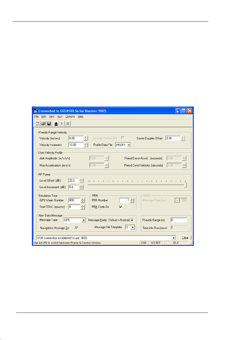
The user interface, shown in Figure 1-1, uses standard Windows XP
commands (including keystroke alternatives to using a mouse) and controls.
Figure 1-1 SimCHAN interface
This document refers to:
a) Buttons, such as Clear, with Bold text.
b) Filenames, such as GSS6100.ini, with Bold italic text.
c) Text boxes, such as Velocity (m/sec) with Bold text.
You enter data values by typing the value in the text box, which is referred
to by its name, for example Pseudo Range Velocity – Velocity (m/sec).
Where necessary, this document refers to the area name (Pseudo Range
Velocity) to avoid ambiguity. Alternatively, some text boxes have Up/Down
arrows. Click on these arrows, as required, to select a value from the
presented values.
GSS6100 and SimCHAN user manual
© Spirent Communications Plc 2005 - 2007
1-5
General
Page 14

DGP000814AAA 2-01
Other multiple choice selections use drop-down lists, such as Nav Data
Message – Message Type. Click on the Down arrow to the right of the text
to display the drop-down list. Select the item you want.
Some parameters, such as PRN-PRN Code On have two states (for
example, on or off). Click in the box to select (turn on) PRN-PRN Code
On. A tick mark appears in the box. De-select (turn off) PRN-PRN Code
On, by clicking in the box again. The tick mark disappears.
Some parameters, such as Velocity Profile ON, are disabled and use grey,
rather than black, text and a grey rather than white background to the box.
1.5.1.2 Hardware
This document refers to:
a) The GSS6100 as a signal generator.
b) “Operating” the GSS6100 to produce an RF signal.
1-6
General
GSS6100 and SimCHAN user manual
© Spirent Communications Plc 2005 - 2007
Page 15

2-01 DGP000814AAA
Chapter 2: Introduction
Thank you for purchasing a GSS6100 GPS/SBAS signal generator from
Spirent, world leaders in the field of Satellite Navigation Systems
Simulation.
The GSS6100 is a precision, stand-alone, single-channel, L1 C/A code GPS
signal generator that uses the SimCHAN control software. Typically the
GSS6100 is used to evaluate GPS/SBAS receivers and applications for the
GSS6100 include design verification, production test, comparative
evaluation, statistical data-generation through extended and repeated tests,
and incoming product test.
The Global Positioning System (GPS) is based upon a constellation of earthorbiting satellites supporting world-wide precise positioning, navigation and
timing for both terrestrial and earth orbiting vehicles.
Satellite Based Augmentation Systems (SBAS) provide enhanced accuracy,
availability and integrity for GPS users in the civil community via one or
more geosynchronous satellites. The Wide Area Augmentation System
(WAAS) is a system planned for the continental United States. Similar
compatible systems are also planned for Europe (EGNOS) and the Far East
(MSAS).
The GSS6100 fully supports both standard GPS and SBAS.
2.1 SimCHAN or remote operation
You can control the GSS6100 in one of two ways:
SimCHAN - a user-friendly software package that communicates with the
GSS6100 using the USB bus.
Remote Control - in this mode, you use Spirent’s proprietary remote
command set to the signal generator. You can apply the remote command
set using the IEEE or RS232 interfaces.
Because the remote command set is closely aligned with Spirent’s previous
single channel products (the GSS4100 and GSS4700), porting any existing
remote control applications to the GSS6100 is a straightforward exercise.
Note: Both modes of operation offer identical control capability.
GSS6100 and SimCHAN user manual
© Spirent Communications Plc 2005 - 2007
2-1
Introduction
Page 16

Page 17

2-01 DGP000814AAA
Chapter 3: Hardware overview and installation
This section gives an overview of the indicators and connectors present on a
GSS6100; and how to connect it to the host PC.
Spirent Specification, reference
g), gives full details of the connectivity and
signals produced by the GSS6100, together with environmental information.
3.1 Front panel
Figure 3-1 shows the GSS6100 front panel. Table 3-1describes the front
panel indicators and connector.
Figure 3-1 GSS6100 front panel
RF
POW ER HEAL T H
GSS6 1 00 GPS/ SBA S Si gn al G en er a t o r
OUTPUT
ACTIVE
Table 3-1 Front panel indicators and connector
Indicator Type Description
POWER LED ON when ac power connected and internal power
supply operational.
HEALTH LED Normally ON.
Flashes at 1 Hz when an error detected.
Flashes at 4Hz while acquiring external reference
lock.
spi re nt com .co m
ACTIVE LED ON when the signal generator is operating.
Flashes when awaiting an external trigger signal on
rear panel TRIG IN
Connector Type Description
Primary
RF Output
GSS6100 and SimCHAN user manual
© Spirent Communications Plc 2005 - 2007
Co-axial
type N
Provides a composite GPS/SBAS signal
Hardware overview and installation
3-1
Page 18

Page 19

2-01 DGP000814AAA
3.2 REAR PANEL
Figure 3-2 GSS6100 rear panel
Made in U.K.
MODEL: GSS6100
S/N: XXXX
GSS6100 and SimCHAN user manual
© Spirent Communications Plc 2005 - 2007
Hardware overview and installation
3-1
Page 20

DGP000814AAA 2-01
Table 3-2 Rear panel connectors
Connector Type Description
MON/CAL Output SMA female Provides a high-level version of the front panel RF output.
AUX OUTPUT 25-way D type See Table 3-3
TRIG IN BNC Allows an external trigger signal to start a simulation.
TTL level compatible:
-0.5 V < Low < +0.8 V
+2.0 V < High < +5.5 V
50 input impedance
Section
5.6 shows timing details.
EXT REF IN BNC Locks the GSS6100 to an external frequency reference.
10 MHz OUT BNC Internal OCXO reference output.
HOST (USB) USB downstream connector Control and data connection to the host PC.
RS232 9-way D type Control and data connection to a remote terminal.
HOST (IEEE-488) IEEE-488 Control and data connection to a remote terminal.
Power in/switch/fuse IEC AC power in, see reference g)
Reference g) gives further details of the rear panel connectors.
3-2
Hardware overview and installation
GSS6100 and SimCHAN user manual
© Spirent Communications Plc 2005 - 2007
Page 21

2-01 DGP000814AAA
N
N
d
N
d
N
d
N
d
Table 3-3 1 PPS IN / OUT 25 way connector pin-out
Pin Function
11PPSIN1*
2 1PPS OUT2*
3 Reserved
4 Reserved
5 Reserved
6 Reserved
7 Reserved
8 C/A CLOCK*
9 CODE 1PPS*
10 C/A EPOCH*
11
AV DATA*
12 C/A CODE*
13
ot connecte
14 Ground for 1PPS IN
15 Ground for 1PPS OUT
16
ot connecte
17 Ground
18 Ground
19
20
ot connecte
ot connecte
21 Ground for C/A CLOCK
22 Ground for CODE 1PPS
23 Ground for C/A EPOCH
24 Ground for NAV DATA
25 Ground for C/A CODE
Note:
i) Input signals marked * are 50 ohm terminated.
ii) Output signals marked * are 50 ohm drive capable.
1 In combination with the External Reference input, 1PPS IN can be used to synchronise the simulator to an external system, see
Section 5.6, TTL level compatible.
2 TTL level compatible, nominal pulse width 100ms
GSS6100 and SimCHAN user manual
© Spirent Communications Plc 2005 - 2007
3-3
Hardware overview and installation
Page 22

2-01 DGP000814AAA
3.3 Installation and connection to host PC
Note: Before connecting the GSS6100 to the PC, you must install the
SimCHAN software.
Note: Before running SimCHAN the Power and Health LEDs on the front
panel of the GSS6100 must be continuously illuminated.
Using your chosen interface, connect the GSS6100 to the controlling host
PC. The interfaces available are either USB for SimCHAN Software
operation or RS232 / IEEE.488 cable for remote control.
Note: Spirent recommends that users new to the GSS6100 use SimCHAN
before moving onto remote operation. Using SimCHAN for set-up, control
and adjustment of the signal generator is more instructive.
Apply ac power to the GSS6100 and switch it on.
Note: The power input to the GSS6100 is auto sensing for 100-120V or 220240V operation.
After a brief power-up sequence, the POWER and HEALTH LEDs on the
GSS6100front panel illuminate continuously to show correct operation.
The GSS6100 is now ready for remote control operation.
Alternatively, you can start SimCHAN by double-clicking the SimCHAN
icon on the desktop or by using the shortcut in the Windows Start menu.
3-4
Hardware overview and installation
GSS6100 and SimCHAN user manual©
Spirent Communications Plc 2005 - 2007
Page 23

2-01 DGP000814AAA
Chapter 4: Principles of operation
4.1 Overview
The GSS6100 requires instructions to configure and commence operating
the signal generator. The SimCHAN software provides these instructions
using the USB bus; or by command sequences transmitted to the GSS6100
using the IEEE-488 bus or an RS232 port.
Regardless of which method of control you have selected, the GSS6100 has
three software states, Halt, Arm and Run.
In the Halt state, you configure the next signal generator operation run by
selecting parameters such as the satellite PRN number, navigation message
parameters (TOW, Week Number), initial power/velocity and any hardware
conditions such as external reference lock or external trigger control.
Once you have set these attributes, the GSS6100 must be set into the Arm
state.
The Arm state is an interim step prior to setting the GSS6100 into the Run
state. The Arm state configures the GSS6100 and allows you to make any
final adjustments to certain parameter types.
Once in the Run state, the GSS6100 is operational and all requested
characteristics are present on the RF output connector.
While in the Run state, you can adjust and control many parameters to suit
the operation profile you need. At the end of the run, the GSS6100 is set
into the Halt state and the process repeated, as required.
Chapter 5: describes each of the available operating and hardware control
parameters. For clarity, these descriptions use the SimCHAN graphical
interface and include a cross-reference to all applicable remote control
commands.
Chapter 6: gives a full listing of the remote control commands.
GSS6100 and SimCHAN user manual
© Spirent Communications Plc 2005 - 2007
Principles of operation
4-1
Page 24
DGP000814AAA 2-01
4.2 SimCHAN interface
SimCHAN lets you set and adjust in real time, the operating parameters of
the GSS6100. It also displays messages.
SimCHAN has three main areas, see
a) The menu and tool bar.
b) The main area.
c) The status bar.
Figure 4-1 SimCHAN interface
Figure 4-1:
4-2
Principles of operation
GSS6100 and SimCHAN user manual©
Spirent Communications Plc 2005 - 2007
Page 25

2-01 DGP000814AAA
4.2.1 Controlling the GSS6100
You can set the Arm, Run and Halt actions using:
a) The Run menu.
b) The SimCHAN Toolbar buttons.
c) The Hot keys: Ctrl+A (Arm), Ctrl+R (Run) and
Ctrl+H (Halt).
Note: Selection using keystrokes to open Menu items and Hot keys are only
effective when SimCHAN is active, that is, the title bar of SimCHAN is
highlighted. Alt+F6 toggles SimCHAN to the active state.
4.2.2 Help
The Help menu lets you select HTML format versions of the GSS4100 user
manual and the GSS6100 user manual. You can also press F1 to open the
Help menu.
Click on About to see details on the GSS6100 signal generator connected to
the PC and the version of SimCHAN.
4.2.3 Status bar
The Status Bar has fields that show:
a) The state of SimCHAN
b) The state of operation of the signal generator,
c) Internal/External Frequency Reference signal,
d) Presence of a working USB connection.
GSS6100 and SimCHAN user manual
© Spirent Communications Plc 2005 - 2007
Principles of operation
4-3
Page 26

Page 27

2-01 DGP000814AAA
Chapter 5: GSS6100 operating details
All parameter settings you apply to the GSS6100 are written to a file. You
can save this parameter file using the File menu. The default parameter file
extension is .gss.
A parameter file can be loaded before SimCHAN runs. Using a parameter
file lets you easily and quickly run the GSS6100 in a known state.
The New menu resets all SimCHAN parameters to their default states.
You control the GSS6100 using the tool bar.
Table 5-1 details the section numbers for each parameter on the SimCHAN
main dialog box.
Table 5-1 Parameter section references
Parameter Section
Pseudo Range Velocity 5.2.1
Velocity profile 5.2.2
RF Power 5.2.3
Simulation Time 5.2.4
Nav Data Message 5.2.5
PRN 5.2.6
SBAS Message Rate 5.2.7
Pseudo Range 5.2.8
Time into Run 5.2.9
GSS6100 and SimCHAN user manual
© Spirent Communications Plc 2005 - 2007
GSS6100 operating details
5-1
Page 28

DGP000814AAA 2-01
5.1 SimCHAN toolbar
The toolbar, see
Figure 5-1, is the primary method of controlling the
GSS6100.
Figure 5-1 Toolbar
The toolbar also gives access to the file functions:
New Close any open parameters file
Open The Windows Open file dialog box.
Save Saves the current parameters to a file or
Resets the parameters.
prompts for a new file name.
The toolbar also gives the basic control functions of ARM, RUN and
HALT.
5.1.1 ARM the GSS6100
[Remote Command: ARMS see section 6.2.3]
Figure 5-2 ARM button
Click ARM to load the selected parameters to the GSS6100 and to prepare
for a run.
The Status bar shows ‘Ready to Run’ when the arming sequence is
complete.
5-2
GSS6100 operating details
GSS6100 and SimCHAN user manual©
Spirent Communications Plc 2005 - 2007
Page 29

2-01 DGP000814AAA
5.1.2 RUN the GSS6100
[Remote Command: RUNS see section 6.2.26]
Figure 5-3 START button
Clicking START releases the GSS6100 to begin the prepared operation.
Independent of mode (see section
5.5.1.1), you must use this button to start
the GSS6100.
The front panel ‘Active’ LED illuminates
3
after clicking START.
To return to the idle state without running the GSS6100, click HALT.
5.1.3 HALT the GSS6100
[Remote Command: HALT see section 6.2.9]
Figure 5-4 HALT button
Click HALT to abort the operation in progress or terminate the Ready to
Run state.
After you click HALT, SimCHAN and the GSS6100 return to the Idle state.
You can HALT the operation to change parameters.
3
The time at which the RUN command is actioned in the hardware is dependent upon the
selected Ext Trigger mode. The simulation start time will coincide with the next rising edge of
1PPS OUT, if Ext Trigger is ‘disabled’ or in ‘delayed’ mode, or immediately if Trigger mode
‘immediate’ has been selected.
GSS6100 and SimCHAN user manual
© Spirent Communications Plc 2005 - 2007
5-3
GSS6100 operating details
Page 30

DGP000814AAA 2-01
5.2 SimCHAN main area
Use the main area of the SimCHAN interface, see
operating parameters.
Figure 5-5 SimCHAN interface
Figure 5-5, to enter the
5-4
GSS6100 operating details
GSS6100 and SimCHAN user manual©
Spirent Communications Plc 2005 - 2007
Page 31

2-01 DGP000814AAA
5.2.1 Pseudo Range Velocity
[Remote Command: see VCTY section 6.2.36]
This is the rate of change of the Satellite’s simulated Pseudo Range in
metres per second. The allowed values range from -15000.00 to +15000.00
at a resolution of 0.01 meters per second.
Use the Up and Down arrows to the right of the Velocity text box to step the
velocity from –15000.00 through to +15000.00 m/s. You can set the step
size by typing a suitable value in the Increment text box.
Figure 5-6 Pseudo-range velocity area
Note: Each time you click on the Up or Down arrow to the right of the
Velocity Increment text box, the value shown in the Velocity Increment text
box will be added, or subtracted, to the Pseudo Range Velocity
5.2.1.1 Velocity increm ent
The Up and Down buttons to the right of the Velocity text box increment
and decrement the Pseudo Range Velocity by a value defined in the
Velocity Increment text box.
The allowed values of Velocity Increment range from 0.01 to 5000.00
metres per second.
GSS6100 and SimCHAN user manual
© Spirent Communications Plc 2005 - 2007
GSS6100 operating details
5-5
Page 32

DGP000814AAA 2-01
5.2.2 Velocity profiles
[Remote Command: PROF see section 6.2.22]
Select Velocity Profile ON to use a velocity profile. After selecting
Velocity Profile ON you must also select a Profile Data File, see section
5.2.2.2.
This option is only available when the GSS6100 is running. The velocity
profile superimposes a cyclic sequence of changes to the selected Pseudo
Range Velocity.
The velocity profile remains applied until you de-select Velocity Profile
ON.
You can use Velocity Profiles with the remote command:
section
5.2.2.1 More on velocity profiles
6.2.23.
PROS, see
Table 5-2 describes the elements used in velocity profiles. Figure 5-7 shows
these elements.
A velocity profile takes the form of a series of step jerk periods of equal
amplitude and period. These jerk periods then translate into acceleration,
velocity and finally range profiles.
The velocities generated by the profile are in addition to any fixed velocity
specified. The maximum achievable velocity is +/-15000 m/s. Velocities
exceeding these limits will be clipped to the appropriate maximum velocity.
Table 5-2 Elements used in velocity profiles
Parameter
Reference in
Figure 5-7
Unit
Maximum Jerk A m/s3
Jerk Period B s
Constant acceleration
period
C s
Constant velocity period D s
Maximum acceleration E m/s2
5-6
GSS6100 operating details
GSS6100 and SimCHAN user manual©
Spirent Communications Plc 2005 - 2007
Page 33

2-01 DGP000814AAA
Figure 5-7 Velocity Profile Elements
Note: The velocity profile shown in
Figure 5-7 shows either constant or
linearly changing velocity. During the jerk period (which is a period of
linearly increasing/decreasing acceleration) the velocity changes nonlinearly.
The GSS6100 fully models these effects.
Reference
f) documents the profile. It comprises the following sequence:
Constant Initial Velocity Period (D)
Positive Jerk Period (B = Max Acceleration/ Maximum Jerk (A))
Constant Acceleration Period (C)
Negative Jerk Period (as ii)
Constant Positive Velocity Period (D)
Negative Jerk Period (as ii)
Constant Deceleration period (C)
Positive Jerk Period (as ii)
The profile then repeats but with the Jerk sign reversed, producing negative
velocities.
Finally, the entire profile repeats from the start.
GSS6100 and SimCHAN user manual
© Spirent Communications Plc 2005 - 2007
GSS6100 operating details
5-7
Page 34

DGP000814AAA 2-01
5.2.2.2 Profile Data File
[Remote Command: PFIL see section 6.2.21]
Figure 5-8 Profile Data File
Figure 5-8 shows the Profile Data Files available. The GSS6100 firmware
incorporates eight standard profiles PROF1 through PROF8, corresponding
to the profiles defined in reference
f). Table 5-3 details these profiles.
Table 5-3 Stored values for PROF1 to PROF8
Profile
Jerk
amplitude,
3
m/s
Maximum
acceleration,
m/s
2
Period of
constant
acceleration, s
Period of
constant
velocity, s
1 20.0 6.0 1.1 1.1
2 20.0 10.0 2.0 2.0
3 100.0 10.0 4.9 4.9
4 10.0 10.0 0.5 0.5
5 20.0 6.0 3.8 3.8
6 40.0 20.0 7.0 7.0
7 100.0 90.0 22.9 22.9
8 17.5 7.0 4.6 4.6
5-8
GSS6100 operating details
GSS6100 and SimCHAN user manual©
Spirent Communications Plc 2005 - 2007
Page 35

2-01 DGP000814AAA
You can create a User Velocity Profile by first selecting Profile Data File –
USER. This enables the text boxes in the User Velocity Profile area.
Table 5-4 gives the ranges for the User Velocity Profile parameters.
Table 5-4 Parameters for User Velocity Profile
User Velocity Profile Parameter Range
3
2
Jerk Amplitude
Max Acceleration
-100 to 100 m/s
Note: Zero Jerk is not allowed.
-100 to 100 m/s
Period of Const Accel
Period of Const Velocity
0 to 540 s
0 to 540 s
Note: Jerk application period = (max acceleration / 0.01 s)
The jerk application period must be divisible by the interrupt step size,
which is 10ms.
To ensure this is always true, you must manually inspect and modify the
entered jerk.
Note: SimCHAN does not carry out this computation.
You must complete this computation and enter the appropriate data.
For example:
3
a) You require a jerk value of 20 m/s
15.5 m/s
2
. This produces a jerk period of 0.775 seconds.
and use an acceleration of
b) This jerk period is not divisible by 0.01 s (10 ms).
c) First, round the jerk period down to 0.770 seconds.
2
d) With your acceleration of 15.5 m/s
results in a jerk of 20.1298 m/s
, a jerk period of 0.770 s
3
.
e) Now round the jerk period up to 0.780 seconds
2
f) With your acceleration of 15.5 m/s
results in a jerk of 19.8718 m/s
g) Choose the jerk value nearest your required 20 m/s
19.8718 m/s
3
.
, a jerk period of 0.780 s
3
.
3
, that is,
h) Use this jerk in the User Velocity Profile you create.
GSS6100 and SimCHAN user manual
© Spirent Communications Plc 2005 - 2007
GSS6100 operating details
5-9
Page 36

DGP000814AAA 2-01
To save the USER profile for re-use select “Save as” from the SimCHAN
File menu and save to a file of your choice. To recall the settings select
“Open…” from the File menu and recall the saved file. (Note that this
actually saves ALL the current application settings.)
5.2.2.3 Carrier Doppler Offset
[Remote Command: VCTY section 6.2.36]
Figure 5-9 Setting Carrier Doppler Offset
Carrier Doppler Offset can be used to simulate Ionospheric delay type
effects by applying a fixed Doppler velocity offset to the current carrier
Doppler velocity. The code Doppler velocity remains unchanged.
The Carrier Doppler Offset value has a range from –1000.00 through
+1000.00 to a resolution of 0.01 m/s.
5-10
GSS6100 operating details
GSS6100 and SimCHAN user manual©
Spirent Communications Plc 2005 - 2007
Page 37

2-01 DGP000814AAA
5.2.3 RF Power
[Remote Command: LEVL see section 6.2.12]
Figure 5-10 Setting RF Power Level Offset
The RF Power Level Offset may be varied to + or – 20.0 dB of the base
level to a resolution of 0.1 dB.
Note: A value outside the allowed range truncates to the limit value.
5.2.3.1 RF Power Level Offset
The Up and Down buttons to the right of the RF Power Level Offset text
box increment and decrement the RF Power Level Offset by a value defined
by the Level Increment.
You can also click on the slider and drag it to change the RF Power Level
Offset. The slider forces the RF Power Level Offset to a multiple of the
value selected in Level Increment.
To avoid discontinuities at the range limits when using a user-defined Level
Increment, the nearest pre-defined Level Increment value is used, rather
than the user’s value.
5.2.3.2 RF Power - Level Increment
You can set any value, including values greater than the RF Power Level
range of 40.0 dB.
Alternatively a value may be selected from the range of pre-defined values
by selecting the Up/Down arrow buttons next to the control.
GSS6100 and SimCHAN user manual
© Spirent Communications Plc 2005 - 2007
GSS6100 operating details
5-11
Page 38

DGP000814AAA 2-01
5.2.4 Simulation Time
Here, simulation refers to operation of the GSS6100.
5.2.4.1 GPS week number
[Remote Command: WEEK see section 6.2.37]
Figure 5-11 Setting Simulation Time
GPS Week Number is closely linked with the start of week since it defines
the GPS week for the simulation. GPS week zero is defined as starting at
00:00 hours, Sunday 6
th
January 1980.
For example, the default value of 800 corresponds to the week starting
Sunday, 7
th
May 1995. GPS week numbers greater than 1023 will be
truncated internally modulo 1024, i.e. Week 1025 is treated as week 1.
The week number may be entered as a value between 0 through 9999.
5.2.4.2 Time of Week
[Remote Command: ZCNT see section 6.2.39]
This value is the time into the week expressed in GPS Epochs that will be
applied at the start of the operation. When the GSS6100 is running, this
value increments to show the current Time of Week.
The allowed values range from 0 through 403196 in steps of 4 GPS Epochs.
1 GPS Epoch = 1.5 Seconds
5-12
GSS6100 operating details
GSS6100 and SimCHAN user manual©
Spirent Communications Plc 2005 - 2007
Page 39

2-01 DGP000814AAA
5.2.5 Nav Data Message
[Remote Command: NDSW see section 6.2.16]
You can prevent generation of the Nav Data Message by de-selecting
Navigation Message On.
Figure 5-12 Nav Data Message dialog box
5.2.5.1 Message Type
[Remote Command:, SIGT see section 6.2.29]
Select either GPS or SBAS in Nav Data Message – Message Type.
With the GPS setting, the RF signal from a GPS type satellite is produced
and the control options appropriate to GPS are activated.
With the SBAS setting, the RF signal from an SBAS type satellite is
produced and the control options appropriate to SBAS are activated.
Note: You must select SBAS to enable SBAS Message Rate.
5.2.5.2 Message Parity
[Remote Command: PRTY see section 6.2.24]
Parity errors may be produced on the Nav Data Message by de-selecting
Message Parity. This inverts each parity bit, thus invalidating it.
Note: The data message is buffered in hardware. Changing the parity status
while the GSS6100is running results in a delay before the change is
reflected in the RF output.
Spirent recommend you set-up this feature while SimCHAN is idle and the
GSS6100 is not operating.
GSS6100 and SimCHAN user manual
© Spirent Communications Plc 2005 - 2007
GSS6100 operating details
5-13
Page 40

DGP000814AAA 2-01
5.2.5.3 Message File Template
[Remote Command: NSEL see section 6.2.20]
The GSS6100 can store up to 8 Message File Templates in its Flash
memory. You can fill these eight memory “slots” with four GPS Navigation
Message Templates and four SBAS Correction Data message Templates.
Selecting a GPS constellation selects Templates for GPS Navigation
Messages; otherwise SBAS Correction Message Templates are selected.
For either GPS or SBAS, a Message File Template number in the range 0
to 3 identifies the appropriate Template. The Message File Template
number shown will be the active selection for the GSS6100, it is used to
generate the Navigation/Correction message component of the RF signal.
5.2.6 PRN
The PRN (Pseudo Random Noise) Number defines the C/A code for the
satellite being produced and equates to the SV ID (Satellite Vehicle
Identity).
5.2.6.1 PRN Number
[Remote Command: SVID see section 6.2.32 & G2D see section
6.2.28]
Figure 5-13 PRN dialog box
The PRN value is constrained to the range 1 to 37 for GPS type satellites
and 120 to 138 for SBAS satellites.
SimCHAN offers a default value of 1 for the GPS constellation and 120 for
an SBAS constellation.
5-14
GSS6100 operating details
GSS6100 and SimCHAN user manual©
Spirent Communications Plc 2005 - 2007
Page 41

2-01 DGP000814AAA
5.2.6.2 PRN Code On
[Remote Command: COSW see section 6.2.5]
Disable PRN code generation by de-selecting PRN Code On.
The GSS6100 is capable of generating any one of the 1023 possible random
sequences associated with the GPS C/A encoder. Each sequence or code is
determined by the start conditions of the G1 and G2 encoders.
The G1 encoder is hardwired to start in the “all ones” state, the G2 encoder,
can start in any state except all zeros.
The G2 start conditions can be described by a ‘G2 delay’, which can take
values between 0 and 1022.
Conventionally, several of the 1023 codes (mainly codes with good
orthogonal properties, such as low cross correlation) have been assigned
PRN numbers, see
Table 5-5.
Note: SimCHAN constrains the PRN assignment to the values allocated for
GPS or SBAS satellites.
Table 5-5 PRN assignments
PRN No. Assignment
1 - 37 GPS
38 - 61 GLONASS
62 - 119 Future GLONASS
120 - 140 GEO/SBAS
141 - 210 Future GNSS/GEO/SBAS/Pseudolites
GSS6100 and SimCHAN user manual
© Spirent Communications Plc 2005 - 2007
GSS6100 operating details
5-15
Page 42

DGP000814AAA 2-01
5.2.7 SBAS Message Rate
[Remote Command: WRTE see section 6.2.38]
Figure 5-14 SBAS dialog box
You must select Nav Data Message – Message Type - SBAS to enable the
SBAS Message Rate.
The Message Rate controls the rate at which the Correction message is
transmitted during an SBAS type operation.
You can choose one of four rates from the drop-down list: 50, 100, 125 and
250 data bits per second. 250 bps is the default setting, which is equivalent
to 500 symbols per second when forward error corrected.
Note: The Message Transmission rate for GPS satellites is fixed at 50 bps.
5.2.8 Pseudo Range
[Remote Command: IPRG see section 6.2.11]
Note: Pseudo Range may only be set while the GSS6100 is idle.
Pseudo Range simulates the distance between the receiver and the satellite
at the start of the run. This ranging effect is produced by delaying the start
of the PRN and data message signals to simulate the desired pseudo range.
The time delay is relative to rising edge of the 1PPS OUT signal (Ext
Trigger mode ‘disabled’ or ‘delayed’ or relative to the External Trigger
pulse itself if Trigger mode ‘immediate’ has been selected, see section
5.5.1.1).
Figure 5-15 Pseudo Range dialog box
Pseudo Range can take any value between 0 and 99999999 metres
(equivalent to 333 ms time delay) and has a resolution of 1 metre.
5-16
GSS6100 operating details
GSS6100 and SimCHAN user manual©
Spirent Communications Plc 2005 - 2007
Page 43

2-01 DGP000814AAA
5.2.9 Time into Run
This shows the elapsed time of the operation, in seconds.
5.2.10 Prompts, Warnings and Errors
[Remote Command: BITE see section 6.2.4]
Figure 5-16 Warning and prompts log window
SimCHAN will display single line text messages describing events that
occur during execution of the program in the text box towards the bottom of
the SimCHAN window.
The messages are stored in time sequence with the latest message displayed.
You can view the record of events by clicking the down arrow on the righthand side of the text box to open the list and then scrolling to view the
messages.
You can clear all messages by clicking Clear.
Note: SimCHAN automatically removes old messages and it is not normally
necessary to clear old messages.
GSS6100 and SimCHAN user manual
© Spirent Communications Plc 2005 - 2007
GSS6100 operating details
5-17
Page 44

DGP000814AAA 2-01
5.3 Navigation Data Template
The GPS Navigation message and the Correction Data message in SBAS
mode are generated from templates pre-loaded in the GSS6100 flash
memory. The templates provided for each of these modes should be
sufficient for most test purposes. Spirent also provides these templates as
ASCII files.
The GPS Navigation Message carries date and time information that
increments at the 6 second GPS Epoch rate. This is automatically inserted
by the GSS6100 to match the operation time. The parity field is computed
dynamically by the GSS6100, but data other than Epoch time remains fixed.
To allow you to meet specific testing requirements, you can load a further 3
templates of each type, using either the NSAV command or using the
SimCHAN graphical interface and the USB bus.
Templates are plain text files and may be examined and altered by any text
editor such as Windows Notepad.
Save modified templates to the SimCHAN program folder, typically
C:\Documents and Settings\All Users\Application Data\Spirent
Communications\SimCHAN.
Note: GPS Navigation message templates must use the NAV extension and
an SBAS Correction data message must use the WAS extension.
To load a specific template, use the Options-Load Navigation Message
Template dialog box, see
Figure 5-17.
Figure 5-17 Load Navigation Template
5-18
GSS6100 operating details
GSS6100 and SimCHAN user manual©
Spirent Communications Plc 2005 - 2007
Page 45

2-01 DGP000814AAA
a) Select the template type, either GPS or SBAS.
b) Select a template from the Template File Available drop-down
list.
c) Use Template Slot ID to select the ID number of the GSS6100
flash memory location that will hold the template. There are
four locations numbered 0 to 3.
Note: ID number 1 is the default to prevent overwriting the GSS
supplied template pre-loaded in template number 0.
d) Click Load to load and use the selected template.
For a full description of default message parameters and how to define user
*.NAV and *.WAS files see
Appendix F: and Appendix G:.
Appendix J: gives details of a Nav Data template that produces a
programmable Nav Data message. You can only use this template with
firmware version 1.11 on.
Note: You must save all user-defined Nav Data files to the following folder:
C:\Documents and Setting\All Users\Application Data\Spirent
Communications\SimCHAN\
Note: You must enter the full path and filename in the Load Navigation
Message Template screen, for example:
C:\Documents and Setting\All Users\Application Data\Spirent
Communications\SimCHAN\filename.nav
GSS6100 and SimCHAN user manual
© Spirent Communications Plc 2005 - 2007
GSS6100 operating details
5-19
Page 46

DGP000814AAA 2-01
5.4 AutoGO
The GSS6100 has an alternative operating mode that causes it to commence
running a stored scenario immediately it is powered on. No external
command is required.
To enable AutoGO:
a) Start SimCHAN
b) Ensure the GSS6100 is connected,
c) Apply the desired initial settings,
d) Select Options - Set AutoGO
e) The settings are applied to the GSS6100.
f) Options - Set AutoGO will now show Disable AutoGO
indicating the GSS6100 is set to run in the AutoGo mode.
g) When the GSS6100 is powered on, it will immediately
commence running using the stored settings.
If SimCHAN is started while the GSS6100 is operating in AutoGo mode,
SimCHAN will display the initial settings stored in the GSS6100’s flash
memory. The GSS6100 will continue to run with SimCHAN active but
SimCHAN will not display the running state or update the scenario time
displays to reflect the progress of the scenario.
To stop AutoGO and use SimCHAN:
a) Click the ARM button followed by the STOP button.
b) The GSS6100 will HALT.
Now you can use SimCHAN normally.
Note: When next powered on, the GSS6100 will start in AutoGO mode,
unless you disable AutoGO.
To disable AutoGO:
a) Start SimCHAN
b) Ensure the GSS6100 is connected.
c) Select Options - Disable AutoGO.
d) The settings are deleted from the GSS6100 flash memory and
normal operating mode is enabled.
5-20
GSS6100 operating details
GSS6100 and SimCHAN user manual©
Spirent Communications Plc 2005 - 2007
Page 47

2-01 DGP000814AAA
5.4.1 Limitations of AutoGO
1. External Trigger cannot be utilised.
2. If an external reference frequency signal is applied, there will be
a period (after the GSS6100 starts running) when the RF signal
is disturbed and out of specification. This state will continue
until the GSS6100 locks to the reference signal.
The HEALTH LED on the front panel will flash until the
GSS6100 locks to the reference signal.
GSS6100 and SimCHAN user manual
© Spirent Communications Plc 2005 - 2007
GSS6100 operating details
5-21
Page 48

DGP000814AAA 2-01
5.5 Hardware options and settings
View the Hardware Options and Settings dialog box by clicking Options
– Hardware Settings.
Figure 5-18 Hardware Options and Settings
The Hardware Options and Settings dialog box, see
Figure 5-18, displays
the Serial Number of the connected GSS6100 unit and the Versions/Release
numbers of the various Firmware elements loaded into the unit. The
following sections describe the hardware related parameters that can be
controlled and selected.
[Remote Command to check firmware version: *IDN? See 5.1.4]
5-22
GSS6100 operating details
GSS6100 and SimCHAN user manual©
Spirent Communications Plc 2005 - 2007
Page 49

2-01 DGP000814AAA
5.5.1.1 External T rigger
[Remote Command: TRIG see section 6.2.35]
If you want to start the GSS6100 from an external event, you must set the
External Trigger mode.
Regardless of Trigger mode, you must click RUN to start operating the
GSS6100
4
.
The External Trigger options are:
1) Disabled No external trigger is required to start the run. The run will start
when the next internal 1PPS event occurs (‘RUN’ 1PPS event).
Operatting start time is coincident with the rising edge of the
1PPS OUT signal
2) Immediate In this mode the internal 1PPS signal is stopped and restarted
immediately on the rising edge of a signal applied to the External
Trigger connector. The operation will start and 1PPS OUT will
transition high approximately 600-700nsecs after the applied
External Trigger signal.
3) Delayed In this mode the GSS6100 waits for the External Trigger signal
to be applied but will hold off commencing the operation until
the next internal 1PPS event occurs (‘RUN’ 1PPS event).
Operation start time is coincident with the rising edge of the
1PPS OUT signal
4
It should be noted that this is different to the STR4775 product where the External Trigger
is applied whilst the Signal generator is in the ARMED state. With the GSS6100 the signal
generator must be in the RUN state before for the Ext Trigger signal will be actioned.
GSS6100 and SimCHAN user manual
© Spirent Communications Plc 2005 - 2007
GSS6100 operating details
5-23
Page 50

DGP000814AAA 2-01
5.5.1.2 1PPS Out
[Remote Command: TIOP see section 6.2.33 & TIOP ? section
6.2.34]
1PPS Out is used to select the signal on the 1PPS rear panel connector. You
can select from:
1PPS
Continuously outputs 1Hz pulses with the rising edge of each pulse
coincident with the GPS 1-second epoch produced by the GSS6100
Gated
As 1PPS, but the signal is disabled before a run, the first rising edge
coincides with operation time 0, start of run.
Rising
High
Low
5.5.1.3 IEEE Primary Address
A single rising edge occurs at operation time 0, start of run
Sets signal permanently high
Sets signal permanently low
[Remote Command: GPIB see section 6.2.8]
The GSS6100 is controlled using the IEEE-488 bus, using the IEEE primary
address number (PAD) you select in the IEEE Primary Address text box.
The IEEE Primary Address can take values in the range 1 through 30.
5.5.1.4 Info Mask.
This is a debug facility and is disabled in normal use.
5-24
GSS6100 operating details
GSS6100 and SimCHAN user manual©
Spirent Communications Plc 2005 - 2007
Page 51

2-01 DGP000814AAA
5.5.1.5 Reference Fre quency
[Remote Command: EREF see section 6.2.6 & EREF ? see
section
6.2.7]
The GSS6100 can detect the presence of an external frequency reference
signal but cannot automatically determine the frequency. The GSS6100 will
automatically lock to the external signal, but only achieves a fully stable
lock when the External Frequency is correctly declared.
Select the frequency of the external frequency reference using the
Reference Frequency – External Frequency drop-down nd click on the
reference frequency you want to use. The supported external frequencies are
1, 5 and 10MHz.
The GSS6100 will automatically seek phase lock with the supplied signal.
The Locked / Unlocked symbols indicate when a stable phase lock occurs.
Generally, it takes between 10 and 20 seconds to achieve phase lock.
The External Reference Phase lock is replicated on the Status Bar of the
Main Display. This is grey when no Reference signal is being detected, Red
when out of lock and Green when locked
Note: You cannot operate the GSS6100 while the reference frequency is
unlocked.
You cannot attempt to phase lock wile the GSS6100 is operating.
If the reference frequency becomes unlocked during operation, an error will
occur.
Note: Before attempting to phase lock to an external reference frequency,
wait at least 15minutes after switch on to allow the GSS6100 10MHz OCXO
to stabilise.
GSS6100 and SimCHAN user manual
© Spirent Communications Plc 2005 - 2007
GSS6100 operating details
5-25
Page 52

DGP000814AAA 2-01
5.6 Synchronisation
The GSS6100 signal generator incorporates input and output signal ports
which can be used in various ways to synchronise time between the
GSS6100 signal generator and the remainder of the system. This section
describes how to use the 1PPS IN and/or TRIG IN inputs to achieve
synchronisation.
The GSS6100 signal generator maintains time internally by means of a time
counter, clocked by an internal 10MHz clock. Operations always start on a
one-second rollover of this timer.
The timer may be synchronised to an external system before starting an
operation by applying a rising edge to the 1PPS IN rear panel input
5
. Then
operations may be started either by appropriate timing of the software run
command (Trigger Mode: Disabled); or by selecting Delayed Trigger
Mode and applying a rising edge to the TRIG IN input. Both cause the
operation to start on the next one-second rollover of the timer.
Alternatively, you can select Immediate Trigger Mode, which forces the
timer to a point just before the one second rollover and freezes it until a
rising edge is detected on the TRIG IN input, the operation starts running
after a short delay.
Note: the use of TRIG IN (Immediate Trigger Mode) together with 1PPS IN
is inappropriate, as both would be attempting to control the timer. However,
TRIG IN (Delayed Trigger Mode) can be used with 1PPS IN.
If coarse synchronisation to your system is sufficient, the methods described
above may be used with no additional considerations. However certain fixed
delays, and uncertainties of the order of 100ns will exist.
To get precise synchronisation you must supply the GSS6100 with an
external 10MHz frequency reference and observe certain timing
requirements between the 1PPS IN and/or TRIG IN signals and the EXT
REF IN signal. The following sections detail these requirements.
5
Note this is a 50Ω input and the pulse width of incoming signals should be ≥120nsecs.
5-26
GSS6100 operating details
GSS6100 and SimCHAN user manual©
Spirent Communications Plc 2005 - 2007
Page 53

2-01 DGP000814AAA
A
A
5.6.1 1PPS IN
The required timing of the rising edge of 1PPS IN with respect to EXT REF
IN, and the resulting timing of the start of operation is shown in
Figure 5-19.
Provided these timing requirements are adhered to, the RF signal timing will
be fixed and repeatable with respect to REF IN every time an operation is
run.
The EXT REF IN signal may be a square wave as shown, (for example a
TTL/CMOS signal) or a sinusoid. Whatever the REF IN input waveform,
the timing reference point is the ac zero crossing of the signal. Note that
alignment of 1PPS OUT as shown in the diagram does not occur
immediately, but one second after 1PPS IN is detected. Note also that the
1PPS IN input is disabled whilst an operation is running, i.e.
synchronisation can only take place whilst in the HALTED state.
Figure 5-19 Timing requirements for 1PPS IN and resulting start
6
timing
Timing requirements for 1PPS IN:
EXT_REF_IN_(10MHz
thold (20 ns min)
tsetup (10ns min)
1PPS_IN
(Internal_10MHz_clock)
One second later 1PPS OUT will be aligned as follows:
1PPS_OUT
Start of simulation:
Simulation_state
RF_State
RMED
RMED RUNNING
5.6.2 TRIG IN – Immediate Mode
When using the Immediate Trigger mode, the timing requirements for the
rising edge of TRIG IN with respect to EXT REF IN are the same as for the
1PPS IN input (i.e. 10ns setup, 20ns hold). However there is a delay of six
6
The delay between the 1PPS OUT rising edge and its resulting phase transition at RF, seen
at the RF Output Port, is nominally 0secs ±5 nsecs (1σ) RSS
GSS6100 and SimCHAN user manual
© Spirent Communications Plc 2005 - 2007
5-27
GSS6100 operating details
Page 54

DGP000814AAA 2-01
A
A
10MHz clock cycles after the trigger is recognised before the operation
starts. This is shown in
Figure 5-20.
Figure 5-20 Timing requirements for TRIG IN (Immediate Mode) and
resultant start timing
XT_REF_IN_(10MHz)
thold (20 ns min)
TRIG_IN
Internal_10MHz_clock
1PPS_OUT
tsetup (10ns min)
Simulation_state
RF_State
RMED
RMED RUNNING
5.6.3 TRIG IN – Delayed Mode
In delayed trigger mode, to start on a defined 1PPS event, the rising edge of
TRIG IN must occur at least 1.1 milliseconds before the 1PPS OUT rising
edge.
5-28
GSS6100 operating details
GSS6100 and SimCHAN user manual©
Spirent Communications Plc 2005 - 2007
Page 55

2-01 DGP000814AAA
Chapter 6: Remote interface
The GSS6100 can be remotely controlled using the IEEE-488 bus or RS232
serial port
7
; an identical set of control commands are used for each interface
type.
6.1 Interface Types
6.1.1 GPIB
The IEEE Std 488.1 Interface Functions subsets implemented are:
SH1, AH1, T6, TE0, L4, LE0, RL0, PP0, DT0, and C0.
Limited Query/response message handshakes are implemented for the initial
release. Status indication is provided by bit settings of the standard IEEE488 serial poll register to enable the remote controller to monitor basic
operation only.
6.1.1.1 Default IEEE-488 address
The GSS6100 is delivered with the IEEE-488 Primary Address set to 02.
This may be inspected and changed if desired with either the SimCHAN
software over the USB or directly by the GPIB command on the IEEE.488
interface.
To set the address with SimCHAN, start the SimCHAN software and
connect the GSS6100 via the USB. Select ‘Hardware Settings’ on the
Options menu. The current address is displayed and an alternate address
may be selected from a dropdown list. Select OK or Apply to effect the
change.
6.1.2 RS232
The serial port is configured to 38400 BAUD, with 8 data-bits, no parity and
1 stop bit. No handshaking is implemented.
7
Either of the communication interfaces may be used one after the other as long as ONLY one
interface is used at a time.
GSS6100 and SimCHAN user manual
© Spirent Communications Plc 2005 - 2007
6-1
Remote interface
Page 56

DGP000814AAA 2-01
6.2 Command set
All messages are initiated by an ASCII character identifier, such as IDEN,
of at least 4 bytes in length. This may be followed by a variable number of
ASCII encoded parameters depending on the message type, each separated
by one or more space characters.
Several messages may be sent in a single transfer but they must be separated
by one or more space characters, and the complete transfer must end with
EOI asserted for IEEE or <CR><LF> for RS232. The maximum length of a
message transfer must not exceed 256 bytes; if it does the entire transfer will
be discarded.
The maximum length of each ASCII encoded parameter is 9 bytes (digits)
for integer parameters and 64 bytes for floating point parameters (up to 9
decimal places).
Floating point parameters may be supplied in integer or floating point form.
Values will be limited to the ranges and precision stated. Units will be as
stated, qualifying unit codes are not permitted or recognised.
The query response remains valid until one of the following occur; the
response is read, another command query message is received; the RSET
command is received; a DCL or SDC (IEEE only) command is received.
IEEE query responses have EOI asserted on the last byte of the response and
RS232 responses are terminated with a <LF> character.
6.2.1 Notes on the syntax definition
The following syntax elements are used to define the command set options
and constraints.
The short form of terms is indicated in capitals. Otherwise the names are not
case sensitive.
Parameter values are separated from the sub command string by white
space.
[] Items in brackets are optional.
| Indicates a choice of items, one of which must be supplied
<> These items are to be replaced by numeric values etc.
{} Groups Items to form a single syntax item
… Ellipsis indicates an inclusive range of values
6-2
Remote interface
GSS6100 and SimCHAN user manual©
Spirent Communications Plc 2005 - 2007
Page 57

2-01 DGP000814AAA
6.2.2 *IDN?
Query IEEE-488 Device ID String
This query is sent by some IEEE-488 Controller applications, e.g. National
Instruments Test and Measurement Explorer, to identify devices on the
IEEE-488 bus. The device responds with a user-friendly name in ASCII.
The message format is:
*IDN?
Response:
<Manufacturer>,<Model>,<serial number>,<firmware>
Where
<Manufacturer> is Spirent Communications
<Model> is GSS6100
<serial number> is the serial number or zero if not known
<firmware> is the firmware or software revision level, or zero if not
known
Example Response:
Spirent Communications, GSS6100,1234,1-01
6.2.3 ARMS
Prepare to Run
This command informs the signal generator that all the initial conditions for
the operation are complete, and that the signal generator should prepare for
a run command (RUNS).
The message format is:
ARMS
GSS6100 and SimCHAN user manual
© Spirent Communications Plc 2005 - 2007
Remote interface
6-3
Page 58

DGP000814AAA 2-01
6.2.4 BITE
Query the Bite Status
Commands the device to return the state of the various BITE (i.e. error)
flags encoded in an ASCII string. The BITE flags indicate various status and
error conditions.
The response format varies according to the device type.
The message format is:
BITE ?
Response:
Refer to
Appendix E:.
On the GSS6100 BITE conditions cause the front panel HEALTH LED to
flash and the appropriate flag in the BITE response becomes set. In general,
both the LED flashing condition and the flag in the BITE response are reset
by querying the BITE. Certain fatal conditions are not cleared by querying
BITE. To query and clear Command Syntax errors use the SERR command,
6.2.27. An exception to the above is the external reference out of lock
see
indication, where the LED will stop flashing and the flag in the BITE flag is
cleared when lock is achieved without the need to query BITE, provided the
unit is in the Halted state. If an out of lock condition occurs in the Armed or
Running state the flashing LED and BITE flag are latched until queried.
6.2.5 COSW
PRN Code Enable/Disable
Commands the device to transmit or suppress the PRN code modulation.
The code signal sequence progresses whilst modulation is suppressed. Note
that Nav Data modulation is controlled separately (see NDSW)
The message format is:
COSW <code>
Where <code>
0 PRN code turned off
1 PRN code turned on. This is the default state.
6-4
Remote interface
GSS6100 and SimCHAN user manual©
Spirent Communications Plc 2005 - 2007
Page 59

2-01 DGP000814AAA
6.2.6 EREF
Set External Reference Frequency
Sets the expected External Reference Frequency to the specified value. The
value is stored in non-volatile memory for use on power-up. The unit
automatically switches to external reference and seeks Phase Lock
whenever a signal is present on the rear panel connector.
The message format is:
EREF 1MHz | 5MHz | 10MHz
Note the parameter is an ASCII string and must be exactly as shown.
6.2.7 EREF ?
Query External Reference Frequency
Commands the unit to return an ASCII string describing the current External
Reference Frequency setting and the lock status.
The message format is:
EREF ?
Example Response:
EREF 10MHz INT or
EREF 10MHz EXT UNLOCKED or
EREF 10MHz EXT LOCKED
6.2.8 GPIB
Set the GPIB Primary Address
Set the IEEE-488 bus Primary Address of the device. The Primary Address
is saved in non-volatile memory. The unit is supplied with the IEEE-488
address set to 2. The change takes immediate effect and remains in force
indefinitely.
The message format is:
GPIB <gpib address>
Where
<gpib address> An integer in the range 1 to 30.
GSS6100 and SimCHAN user manual
© Spirent Communications Plc 2005 - 2007
Remote interface
6-5
Page 60

DGP000814AAA 2-01
6.2.9 HALT
Stop the GSS6100
Commands the device to terminate the current run and return to the Idle
State. The Z count and Week Number return to the values used to start the
run and the trigger mode is reset to 0 (disabled). All other settings remain
unchanged.
The message format is:
HALT
6.2.10 IDEN
Query the Unit Configuration Details
Commands the device to return an ASCII string describing the Unit’s
identification, and the firmware release numbers.
The message format is:
IDEN
Example Response:
Type GSS6100
Serial Number 0001
Firmware Issue 1.00
Motherboard Revision 1
6.2.11 IPRG
Set Initial Pseudorange
Sets the initial pseudorange. This is manifest as a time delay relative to the
1PPS OUT signal.
The message format is:
IPRG <initial pseudo range>
Where
<initial pseudo range> an integer in the range 0 to 99999999 meters
6-6
Remote interface
GSS6100 and SimCHAN user manual©
Spirent Communications Plc 2005 - 2007
Page 61

2-01 DGP000814AAA
6.2.12 LEVL
Set the RF Output Power Level
Sets the power level for the RF signal at the front panel RF output. The
setting is relative to a base level of –130dBm. The command accepts any
value but clips this to the maximum level, if applicable, and rounds to the
stated resolution.
The message format is:
LEVL <rf power>
Where
<rf power> A floating point number specifying the level in dB.
Range +20.0 to –20.0 to a resolution of 0.1 dB.
6.2.13 LEVL ?
Query the front panel RF signal power level.
Commands the unit to return an ASCII string detailing the current RF signal
power.
The message format is:
LEVL ?
Example Response:
LEVL –5.6
GSS6100 and SimCHAN user manual
© Spirent Communications Plc 2005 - 2007
Remote interface
6-7
Page 62

DGP000814AAA 2-01
6.2.14 MODE
Set the operational mode
Commands the unit into AutoGO mode. A running channel is not halted by
sending the MODE command.
The message format is:
MODE <type>
Where
<type> 1 Sets unit into normal operation.
2 “<string>” Sets unit into AutoGO mode. Signal Generator
configuration is controlled by <string>, e.g. SVID 5
LEVL 0.To action a new script the GSS6100 must be
powered cycled. No error checking applied. To initiate
an automatic run, the entered “string” must complete
with ARMS RUNS.
e.g. To achieve PRN 5, power level +15dB, Doppler
velocity 100 m/s. Use the following:
SVID 5 LEVL 15 VCTY 100 ARMS RUNS
6.2.15 MODE ?
Query the current operational Mode.
This command will not affect a running channel
The message format is:
MODE ?
Example Response:
MODE 1
6-8
Remote interface
GSS6100 and SimCHAN user manual©
Spirent Communications Plc 2005 - 2007
Page 63

2-01 DGP000814AAA
6.2.16 NDSW
Enable/Disable the Navigation Data Message
Commands the device to transmit or suppress the Navigation Data Message.
The message bit sequence progresses whilst the message is suppressed
during an operation.
The message format is:
NDSW <code>
Where:
<code> 0 Suppress transmission of the message
1 Transmits the message
6.2.17 NMOD
Modify the Navigation Data generated from a Nav data template
To ensure there are no data conflicts, the GSS6100 firmware must receive
the NMOD command at least 6 seconds before the end of a NAV frame
boundary. A flag in the “NMOD ?” response indicates if the GSS6100 can
accept updates.
New NMOD commands received by the GSS6100 are entered into a ‘user’
table. At the end of every 30 s frame, the entries in the user table are copied
into a working table used to modify the next frame of data.
The GSS6100 can hold up to 16 entries.
Note: Some NMOD commands, for example IODE and IODC, use two
entries.
The message format is:
NMOD { ? | <Se Wf Bg Lh {value | * }> <$field {value | *}> …}
Note: The NMOD command will accept data in two formats, you can mix
the two formats in one command string, as detailed below:
The first format is the general format <Se Wf Bg Lh {value | *}>.
GSS6100 and SimCHAN user manual
© Spirent Communications Plc 2005 - 2007
Remote interface
6-9
Page 64

DGP000814AAA 2-01
Where:
Se Defines the sub-frame to be altered.
‘e’ is a decimal number in the range 1 to 3
Wf Defines the word to be altered.
‘f’ is a decimal number in the range 1 to 10
Bg Defines the start-bit in the word.
‘g’ is a decimal number in the range 1 to 24
Lh Defines the number of bits to be altered.
‘g’ is a decimal number in the range 1 to 24
value Is a decimal representation of the Lh bits.
The value is read as a signed 32-bit integer. The bottom Lh
bits of the 32-bit signed number will be used.
If a ‘*’ character is used instead of a decimal value, the entry
matching the S,W,B and L values will be removed.
Note: This format lets you modify any valid string of bits.
The second format is more specific <$field {value | *}> and you can modify
specific sequences of bits.
Where:
field Is the name of the NAV data field to be altered
value Is a decimal representation of the Lh bits.
The value is read as a signed 32-bit integer. The bottom Lh bits
of the 32-bit signed number will be used.
If a ‘*’ character is used instead of a decimal value, the entry
matching $field will be removed.
Table 6-1 shows the supported fields and their bit assignments
6-10
Remote interface
GSS6100 and SimCHAN user manual©
Spirent Communications Plc 2005 - 2007
Page 65

2-01 DGP000814AAA
Table 6-1 - NMOD supported fields
Field Sub-frame word Start-bit length
TOC 1 8 9 16
AF2 1 9 1 8
AF1 1 9 9 16
AF0 1 10 1 22
IODE
3 10 1 8
3 10 1 8
SVH 1 3 17 6
1 3 23 2
IODC
1 8 1 8
Note: IODC and IODE have two entries in the table, because IODE
appears in two places in the NAV frame; and the IODC value is split with
the 2 MSBs in one word and the 8 LSBs in another word.
You need only send one NMOD command and the firmware will
enter/delete all the correct fields.
Example messages:
NMOD $TOC 24 S1 W3 B4 L3 4
In response to an “NMOD ?” command the GSS6100 will return a response
with the following format:
NMOD update zcnt entries
Where:
update A decimal value in the range 0 to 1.
‘1’ indicates new entries may be sent
‘0’ indicates new entries may not be sent.
zcnt Represents the Zcount of the next 30s frame of data to be
generated.
entries Indicates how many entries are in the NMOD working table.
GSS6100 and SimCHAN user manual
© Spirent Communications Plc 2005 - 2007
Remote interface
6-11
Page 66

DGP000814AAA 2-01
6.2.18 NSAV
Save Navigation Template
Commands the device to record and save a Navigation Message template
'file'. A sequence of messages are sent to first select one of the eight
template files, then send text for that file, and finally save the text in the
template file. The template information is multi-line ASCII text and is sent
sequentially line by line using the NSAV #FILE.TEXT# message. The
sequence of messages must be terminated by the NSAV #FILE.SAVE#
message. Each individual message must not exceed 256 characters in length
including the line terminating ‘newline’ character. The complete file must
not exceed 32 Kbytes including comments.
The message formats are:
NSAV {GPS | SBAS} <template>
NSAV #FILE.TEXT# <text>
NSAV #FILE.SAVE#
Where:
<template> Integer value as one of 0 | 1 | 2 | 3.
<text> A line of text to be stored in the currently selected
template.
The format rules of each line of text are as follows.
All lines must end with a newline character.
Any line starting with a ! is deemed to be a comment.
All other lines contain data.
Further details are given in
0 and 0, plus the example files supplied.
6-12
Remote interface
GSS6100 and SimCHAN user manual©
Spirent Communications Plc 2005 - 2007
Page 67

2-01 DGP000814AAA
6.2.19 NSAV ?
Query Navigation Template
Commands the unit to return the GPS and SBAS template information.
The message format is:
NSAV ?
The GSS6100 will reply to the query with the size (in bytes) and title string
for each of the GPS and SBAS templates.
GPS 0 6995 !NAV_DATA.NAV
GPS 1 6995 No Record
GPS 2 0 Empty
GPS 3 0 Empty
SBAS 0 25889 !SBAS_CN3.WAS
SBAS 1 0 Empty
SBAS 2 0 Empty
SBAS 3 0 Empty
Templates marked “No Record” were downloaded with earlier firmware
versions and no record was stored.
6.2.20 NSEL
Select Navigation Template
Commands the device to generate the Navigation Message from the named
template. The unit has the capability to store four templates for each of GPS
and SBAS mode. The unit is supplied with the default navigation message
stored in <template> = 0.
The message format is:
NSEL {GPS|SBAS} <template>
Where
<template> Integer value as one of 0 | 1 | 2 | 3.
GSS6100 and SimCHAN user manual
© Spirent Communications Plc 2005 - 2007
Remote interface
6-13
Page 68

DGP000814AAA 2-01
6.2.21 PFIL
Select pre-defined Velocity Profile
Commands the device to use a named set of parameters for generation of the
next velocity profile sequence. In the GSS6100 these sets of parameters are
incorporated in the firmware.
The parameter sets each comprise four floating-point values that together
define the profile. Section
5.2.2.1 gives a detailed description of the profile
shape and its relation to the four parameters.
The selection remains effective until the next RSET, PROS or PFIL
command is processed or the device is powered down.
The message format is:
PFIL <profile name>
Where:
<profile name> PROF1 | PROF2 | … | PROF8
An ASCII string defining the standard profile to be applied.
The PROF1 values will be applied by default.
6.2.22 PROF
Enable/Disable Velocity Profile
Commands the device to either commence or terminate a velocity profile
sequence. The sequence will be either the most recent sequence
selected/defined by the PROF or PROS commands or the default sequence
defined by PROF1.
The message format is:
PROF <code>
Where:
<code> 1 Initiates the velocity profile sequence.
0 Aborts an active sequence.
6-14
Remote interface
GSS6100 and SimCHAN user manual©
Spirent Communications Plc 2005 - 2007
Page 69

2-01 DGP000814AAA
6.2.23 PROS
Select Velocity Profile Parameters
Commands the device to generate the next velocity profile sequence from
the supplied parameters. The supplied parameters are not stored
permanently. It is recommended that this command be sent just prior to each
occasion the Velocity Profile is enabled by the PROF command.
The message format is:
PROS <jerk amplitude><max accel><period const accel><period const
vel>
Where:
<jerk amplitude> floating point number in the range: -100 to +100 m/s
<max accel> floating point number in the range: -100 to +100m/s
3
2
<period const accel> floating point number in the range: 0 to 540 s
<period const vel> floating point number in the range: 0 to 540 s
6.2.24 PRTY
Enable/Disable Set Parity State
Selects the Navigation Message Data Parity as either Normal (as per ICDGPS-200) or Inverted.
The message format is:
PRTY <code>
Where
<code> 1 Set Message Parity to Normal
0 Set Message Parity to Inverted
GSS6100 and SimCHAN user manual
© Spirent Communications Plc 2005 - 2007
Remote interface
6-15
Page 70

DGP000814AAA 2-01
6.2.25 RSET
Reset Device
Commands the device to reset its parameters and operating condition to the
power up state. In practice, HALT and RSET perform quite similar
functions, with the exception that RSET defaults all parameters to a known
state.
The message format is:
RSET
6.2.26 RUNS
Begin operating
Commands the device to start running in operation mode.
The message format is:
RUNS
6-16
Remote interface
GSS6100 and SimCHAN user manual©
Spirent Communications Plc 2005 - 2007
Page 71

2-01 DGP000814AAA
6.2.27 SERR
Query and Clear Syntax Error
Commands the device to return the state of the Command Error flags,
encoded in an ASCII string, together with a string describing the error(s)
and the Command String that caused the error.
The message format is:
SERR ?
Example Response:
SERR 00000001
0, Command not recognised
WEAK 987
6.2.28 G2D
Select PRN by G2 Delay
Commands the device to use a specific G2 delay for its C/A code generator.
The signal generator is capable of generating any one of the 1023 possible
random sequences associated with the GPS C/A encoder. Each sequence or
code is determined by the start conditions of the G1 and G2 coders. The G1
encoder is hardwired to start in the all one state, the G2 encoder, can start in
any state except all zeros. The G2 start conditions can be described by a ‘G2
delay’. This G2 delay can take on values between 0 and 1022. Some of the
1023 codes (mainly codes with good orthogonal properties i.e. Low cross
correlation) have had assigned to them PRN numbers. To select one of these
codes it is easier to use the SVID command.
The message format is:
SG2D <g2delay>
Where
<g2delay> Integer in the range 0 to 1023
GSS6100 and SimCHAN user manual
© Spirent Communications Plc 2005 - 2007
Remote interface
6-17
Page 72

DGP000814AAA 2-01
6.2.29 SIGT
Signal Type
This command defines the required signal type, SBAS or GPS. This setting
determines the form of the Navigation data message transmitted.
The message format is:
SIGT GPS | SBAS
6.2.30 SNUM ?
Query the Device Serial Number
Commands the device to return its serial number.
The message format is:
SNUM ?
Response
An ASCII string of the form 0999.
6.2.31 STAT
Query Status Flags
Commands the device to return the content of the Serial Poll Status Register
in an ASCII string as two hexadecimal digits together with the name of the
operating state. The status register may also be read by a Serial Poll, see
section
0 for the definition of the status bits.
The message format is:
STAT ?
Response:
STAT <hexbyte> <state>
Where:
<hexbyte> is a representation of the 8 bits of the status byte
using hexadecimal digits.
<state> An ASCII string which may one of:
HALTED or ARMED or RUNNING
6-18
Remote interface
GSS6100 and SimCHAN user manual©
Spirent Communications Plc 2005 - 2007
Page 73

2-01 DGP000814AAA
6.2.32 SVID
Select PRN by SVID
Commands the device to generate the PRN sequence for the specified
Satellite ID number as specified in ICD-GPS-200 (GPS) or RTCA-DO229
(SBAS).
The message format is:
SVID <gps prn> | <sbas prn>
Where
<gps prn> Integer in the range: 1 to 37
<sbas prn> Integer in the range: 120 to 138
6.2.33 TIOP
Select 1PPS Output Signal
Selects the format of the signal generated on the rear panel “1 PPS out”
connector.
The message format is:
TIOP <code>
Where
<code> HIGH – The output is always high
LOW – The output is always low
1PPS – The output is always 1 PPS
GATED – The output is 1 PPS only whilst the operation is running
RISE – The output is a rising edge as the operation starts, returning low
when the operation halts
GSS6100 and SimCHAN user manual
© Spirent Communications Plc 2005 - 2007
Remote interface
6-19
Page 74

DGP000814AAA 2-01
6.2.34 TIOP ?
QUERY 1PPS Output Signal
Commands the unit to return an ASCII string describing the current TIOP
setting.
The message format is:
TIOP ?
Example Response:
TIOP 1PPS
6.2.35 TRIG
Select External Trigger
Select Trigger mode. The selection determines how the device will
commence a operation when the RUNS command is applied.
TRIG 0 is the default mode, the device defaults to this for each run, thus the
TRIG command is optional if the external trigger is not used. If an Ext
Trigger pulse is not applied, send the HALT command to return to the
Halted state. Returning to the Halted state resets the Trig mode to 0
(disabled).
The message format is:
TRIG <code>
Where:
<code> 0 Start on next 1PPS event (rising edge) without external trigger
1 Start immediately on a rising edge on the External Trigger input
2 Start at the next 1PPS event following a rising edge on the External
Trigger input
6-20
Remote interface
GSS6100 and SimCHAN user manual©
Spirent Communications Plc 2005 - 2007
Page 75

2-01 DGP000814AAA
6.2.36 VCTY
Set Doppler Velocity
Commands the device to simulate the specified Doppler velocity settings. If
the required Doppler is specified by a single unqualified value then this is
applied as both code and carrier Doppler Velocity. Different Doppler
settings for code and carrier may be specified if required.
The difference between the CODE and CARR Doppler values will be
limited to a maximum of +/- 1000.00 m/s.
The message format is:
VCTY <Doppler> | CODE <Doppler> CARR <Doppler>
Where
<Doppler> Floating point number in the range: -15000.00 to +
15000.00 m/s
A positive Doppler figure yields a decrease in the code/Carrier frequency.
Both values may be entered to a maximum resolution of 0.01m/s.
The CARR <Doppler> value is constrained to be the CODE <Doppler>
value +/- 1000.00 m/s.
6.2.37 WEEK
Select GPS Week Number
Commands the device to commence the next operation run with the
Navigation Message set to simulate signals for the week number specified.
The message format is:
WEEK <GPS week number>
Where
<GPS week number> Integer number in the range 0 to 1023
GSS6100 and SimCHAN user manual
© Spirent Communications Plc 2005 - 2007
Remote interface
6-21
Page 76

DGP000814AAA 2-01
6.2.38 WRTE
Select SBAS DATA Rate
This command selects the data rate for the SBAS message. Default 250
symbols per second. (This does not have any affect on the GPS data
message rate).
The message format is:
WRTE <sbas rate>
Where:
<sbas rate> Integer from the set: 50 | 100 | 125 | 250
6.2.39 ZCNT
Specify the starting time
The command sets the Z Count value that will be inserted in the first frame
of the Navigation Data Message at the start of the next operation run. The
value should be supplied as a multiple of four and other values will be
truncated to a multiple of four.
The message format is:
ZCNT <GPS time into week>
Where
<GPS time into week> Integer in the range: 0 to 403199
The Z Count unit is a period of 1.5 seconds, so that four Z Count units is a
period of six seconds.
6.3 Command availability by mode
Some operation information must be defined before the operation is armed
and run. This means some commands are only available in certain modes.
This is summarised in
Table 6-2.
The Controller application can determine the device's operating state via a
Serial Poll.
Note: The device will regard a command it receives in a wrong state as an
error. The command will not be executed and an error flag will be set. You
can use a Serial Poll to interrogate the error flag.
6-22
Remote interface
GSS6100 and SimCHAN user manual©
Spirent Communications Plc 2005 - 2007
Page 77

2-01 DGP000814AAA
Table 6-2 Commands by Mode
IDLE ARMED RUNNING
*IDN?
ARMS
AUXP
BITE
COSW
EREF
EREF ?
GPIB
IDEN
IPRG
LEVL
LEVL ?
MODE
MODE?
NDSW
NSAV
NSAV ?
NSEL
PFIL
PROS
*IDN?
BITE
COSW
EREF ?
HALT
IDEN
LEVL
LEVL ?
NDSW
PFIL
PROS
PRTY
RSET
RUNS
SERR ?
SNUM ?
STAT ?
TIOP ?
VCTY
*IDN?
BITE
COSW
EREF ?
HALT
IDEN
LEVL
LEVL ?
NDSW
PFIL
PROF
PROS
PRTY
RSET
SERR ?
SNUM ?
STAT ?
TIOP ?
VCTY
PRTY
RSET
SERR ?
SG2D
SIGT
SNUM ?
STAT ?
SVID
TIOP
TIOP ?
TRIG
VCTY
WEEK
WRTE
ZCNT
GSS6100 and SimCHAN user manual
© Spirent Communications Plc 2005 - 2007
Remote interface
6-23
Page 78

DGP000814AAA 2-01
6.4 Serial poll – status bits
The device status is signalled by setting bits in the IEEE-488 Serial Poll
Status Byte Register. The Controller may read this using a Serial Poll
command.
Bits 0 & 1 signal the four operating states of the device:
Bit [1:0]
00 Halted (Idle)
11 Armed (Ready to Run)
10 Running
Bit 2 is a Poll Validity flag. The error flag (bit 7) is undefined whilst the
Poll Validity flag is reset.
Bit 7 is a Command Error flag. This is set when an erroneous command is
decoded. Once set, the bit state is maintained and the front panel health light
flashes until a SERR ? is performed to reset the error condition. Note: the
BITE query gives additional information on the command or parameter
error, which caused the error condition.
6.5 Example command sequences
6.5.1 Example GPS operations
Step 1 – Basic Initialisation
RSET ;Reset Unit (may be omitted if conditions from previous run to be
used)
Serial Poll ;Note - Confirm Validity Bit Set
On Not Error ;Check for Error on each command
;Omitted hereafter for brevity only
Step 2 – Set Initial Conditions
WEEK 987 ;If HALT used, reverts to this at end of run
ZCNT 1236 ;Note – Multiple of 4. Reverts on HALT
SVID 12 ;PRN for GPS Satellite 12. Remains set on HALT
6-24
Remote interface
GSS6100 and SimCHAN user manual©
Spirent Communications Plc 2005 - 2007
Page 79

2-01 DGP000814AAA
LEVL 12.5 ;RF Output level. HALT keeps setting at end of
run
VCTY 0.0 ;No Doppler on Code or Carrier. HALT keeps setting at
end of run
Step 3 – ARM
ARMS ;Align RF and set Ready to Run
Serial Poll ;Wait until Ready to Run Flags set
On Ready to Run ;When Bit 0 = 1 and Bit 1 = 1
Step 4 – Start Operation
RUNS ;Starts on next internal 1PPS pulse
Step 5 – Vary Level and Doppler as desired
LEVL –15.0
VCTY CODE 500.3 CARR 501.3
;500.3m/s with 1m/s carrier offset
;simulating changing atmospheric delay
Step 7 – Revert to Idle when finished
HALT
GSS6100 and SimCHAN user manual
© Spirent Communications Plc 2005 - 2007
Remote interface
6-25
Page 80

DGP000814AAA 2-01
6.5.2 Example with external trigger
Step 1 – Basic Initialisation
RSET ;Reset Operation
Serial Poll ;Note - Confirm Validity Bit Set
On Not Error ;Check for Error on each command
;Omitted hereafter for brevity only
TRIG 1 ;Start immediately on External Trigger
Step 2 – Set Initial Conditions
;or Use Defaults
Step 3 – ARM / RUN Operation
ARMS ;Prepare to run
Serial Poll ;Wait until Ready to Run Flags set
On Ready to Run ;When Bit 0 = 1 and Bit 1 = 1
RUNS ;Set to RUN mode.
Front Panel ‘Active’ LED will be seen to flash. Trigger
may now be applied
Serial Poll ;Check Operation is Running
On Running ;When Bit 0 = 0 and Bit 1 = 1
Step 4 – Vary Level and Doppler as desired
LEVL 20.0
VCTY 10.23
Step 5 – Invoke a Doppler Pulse if desired
VCTY –500.00 ;Set Base Doppler Velocity
PFIL PROF2 ;Select Standard Profile No. 2
PROF 1 ;Start Velocity Profile Sequence
6-26
Remote interface
GSS6100 and SimCHAN user manual©
Spirent Communications Plc 2005 - 2007
Page 81

2-01 DGP000814AAA
;The Sequence repeats indefinitely
PROF 0 ;Stop the sequence
Step 7 – Revert to Idle when finished
HALT
6.5.3 Example with external signals
Step 1 – Basic Initialisation
Serial Poll ;Read the Status Bits
On Not Idle ;Either Bit 0 or Bit 1 set
HALT ;Force Operation to Idle mode
RSET ;Reset Operation
SIGT ;Select GPS Mode
Serial Poll ;Note - Confirm Validity Bit Set
On Not Error ;Check for Error on each command
;Omitted hereafter for brevity only
EREF 10MHZ ;Seek Lock to External Reference
EREF ? ;Query after 30 seconds
On Lock ;Response = EREF 10MHz
;Response = EREF INTERNAL if
;lock not achieved
TRIG 1 ;Start on External Trigger
Step 2 – Set Initial Conditions
;or Use Defaults
Step 3 – ARM /RUN Operation
ARMS ;Prepare to run
Serial Poll ;Wait until Ready to Run Flags set
On Ready to Run ;When Bit 0 = 1 and Bit 1 = 1
RUNS ;Set to RUN mode.
GSS6100 and SimCHAN user manual
© Spirent Communications Plc 2005 - 2007
Remote interface
6-27
Page 82

DGP000814AAA 2-01
Front Panel ‘Active LED will be seen to flash. Trigger
may now be applied
Serial Poll ;Check Operation is Running
On Running ;When Bit 0 = 0 and Bit 1 = 1
Step 4 – Vary Level and Doppler as desired
LEVL 20.0
VCTY 10.23
Step 5 – Revert to Idle when finished
6-28
Remote interface
GSS6100 and SimCHAN user manual©
Spirent Communications Plc 2005 - 2007
Page 83

2-01 DGP000814AAA
Chapter 7: Calibration
The GSS6100 employs a digital architecture to produce accurate and stable
signals. As such it requires little calibration.
There are just two user adjustments: Frequency and Power.
These are both simple potentiometer adjustments. Test equipment
requirements are a suitable frequency counter with a stable reference and an
RF power meter respectively.
Spirent recommends these calibrations be performed annually.
7.1.1 Reference frequency calibration
Use anti-static handling precautions during calibration
This requires a frequency counter capable of measuring 10.00 MHz with at
least 10 digits of accuracy, for example an HP53131A. The frequency
counter should be locked to a frequency standard accurate to < ± 1 x 10
for example an HP5065A Rubidium standard. It is permissible to use a less
accurate standard if you are prepared to accept lower frequency accuracy for
the signal generator.
a) Turn on the GSS6100 and allow at least 30 minutes for the
internal oscillator to stabilise.
b) Attach the frequency counter to the 10 MHz OUT BNC
connector on the rear panel.
c) Remove ‘Calibration Void if Broken’ label covering from the
10 MHz Ref Cal adjustment port.
d) Use the frequency adjustment potentiometer to achieve a
frequency reading of 10 MHz ± 0.02 Hz.
e) Re-cover the 10 MHz Ref Cal port with an appropriate
calibration label.
This concludes reference frequency calibration.
-9
,
GSS6100 and SimCHAN user manual
© Spirent Communications Plc 2005 - 2007
7-1
Calibration
Page 84

DGP000814AAA 2-01
7.1.2 Power level calibration
This requires an RF power meter capable of measuring a frequency of
1.57542 GHz and power levels between –50 dBm and –60 dBm, for
example an HP E4418B. Ensure that the power meter is calibrated according
to the manufacturer’s instructions, including any adjustments for sensor
calibration factor and frequency.
a) Turn on the GSS6100.
b) Remove the 50 ohm termination from the MON / CAL port
connector on the rear panel of the unit. Retain for later
replacement.
c) Attach the RF power meter to the MON/CAL port.
d) Allow 15 minutes for the GSS6100 to stabilise.
e) Remove the ‘Calibration Void if Broken’ label covering from
the IF Level Cal adjustment port.
f) Select the menu item Options-Power Calibration.
g) Follow the on-screen prompts.
First, SimCHAN sets up a calibration signal on the rear panel
MON/CAL port
SimCHAN then calculates and displays the power level you
must set at the MON / CAL port.
h) Adjust the IF Level Cal potentiometer to get this power level at
the MON / CAL port.
i) You must set this power level to within ±0.05 dB.
j) Re-cover the IF Level Cal adjustment port with an appropriate
calibration label.
k) Remove the RF power meter from the MON / CAL port.
l) Replace the 50 ohm termination on the MON / CAL port.
This concludes power level calibration.
7-2
Calibration
GSS6100 and SimCHAN user manual©
Spirent Communications Plc 2005 - 2007
Page 85

2-01 DGP000814AAA
Appendix A: Installing SimCHAN
The SimCHAN software controls the GSS6100 over the USB bus. The
SimCHAN USB interface uses the Microsoft Plug and Play Manager to
install the GSS6100 USB driver; so SimCHAN software must be installed
BEFORE the GSS6100 is connected to the PC.
The first time the GSS6100 connects to the host PC, the Found New
Hardware Wizard installs the required drivers.
A.1 Install SimCHAN
Do not connect the GSS6100 to the host PC.
To install the operating software on your system hard disk, place the
supplied CD into the CD-ROM drive. The SETUP program will normally
auto-run, if it does not then simply run the application SETUP.EXE in the
root directory on the CD.
This will start an InstallShield script that will guide you through the
Installation process, see
Figure 7-1 InstallShield wizard - welcome
Figure 7-1.
The Welcome screen confirms that you are about to install the SimCHAN
software. Progress through the installation stages by clicking Next. You
may change items you have entered or selected by clicking Back.
GSS6100 and SimCHAN user manual
© Spirent Communications Plc 2005 - 2007
A-1
Installing SimCHAN
Page 86

DGP000814AAA 2-01
Click Cancel to abort the installation.
Figure 7-2 to show typical InstallShield wizard screens.
Figure 7-2 SimCHAN licence agreement
The Installation program installs SimCHAN in a sub-folder of C:\Program
Files. Click Browse to select an alternative location, see
Figure 7-3.
Figure 7-3 Select installation folder
The Installation program creates shortcuts you can use to start SimCHAN.
The name of the shortcut in the Windows Start menu is SimCHAN.
A-2
Installing SimCHAN
GSS6100 and SimCHAN user manual©
Spirent Communications Plc 2005 - 2007
Page 87

2-01 DGP000814AAA
Alternatively, you can store the shortcut in an existing folder by selecting
the folder name from Existing Folders, see
Figure 7-4.
Figure 7-4 SimCHAN shortcut folder
Click Next to begin the installation. The installation loads the following
USB driver files:
a) GSS6100.ini, installed in Windows\INF or WINNT\INF
b) GSS6100.sys, installed in Windows\System32\Drivers or
WINNT\System32\Drivers.
After the installation is finished, you do not have to re-boot the PC.
A.2 Removing SimCHAN
The initial installation creates an Uninstall file that identifies the installed
files for removal.
Begin the process by either inserting the Installation CD or using the
Add/Remove Programs facility in the Control Panel.
The Uninstall program will prompt you to confirm that you wish to uninstall
the software. The Uninstall program removes files created by the
Installation process and removes any folders created during installation that
are empty.
Note: Folders containing files added after installation, such as user created
parameter files, will not be deleted when SimCHAN is removed.
GSS6100 and SimCHAN user manual
© Spirent Communications Plc 2005 - 2007
Installing SimCHAN
A-3
Page 88

DGP000814AAA 2-01
A.3 First use
When you connect the GSS6100 to the PC for the first time, you will see the
Windows XP Found New Hardware Wizard, see
Figure 7-5 to Figure 7-9.
Figure 7-5 Found new hardware wizard - 1
Select No, not this time and click Next.
Figure 7-6 Found new hardware wizard - 2
Select Install the software automatically (Recommended) and click Next.
A-4
Installing SimCHAN
GSS6100 and SimCHAN user manual©
Spirent Communications Plc 2005 - 2007
Page 89

2-01 DGP000814AAA
Figure 7-7 Found new hardware wizard - 3
Click Continue Anyway
Figure 7-8 Found new hardware wizard - 4
The installation starts. When the installation is completed, click Next
GSS6100 and SimCHAN user manual
© Spirent Communications Plc 2005 - 2007
A-5
Installing SimCHAN
Page 90

DGP000814AAA 2-01
Figure 7-9 Found new hardware wizard - 5
The last window advises you the installation is complete. Click Finish.
A-6
Installing SimCHAN
GSS6100 and SimCHAN user manual©
Spirent Communications Plc 2005 - 2007
Page 91

2-01 DGP000814AAA
Appendix B: Updating firmware
The current firmware issue may be checked using the SimCHAN menu
Options-Hardware Settings, see section
You will not normally need to change or replace firmware.
The GSS6100 Flash memory device is capable of holding multiple
application images. A default image is loaded during manufacture and never
overwritten. Further images may be stored at different re-programmable
memory locations. The boot code will always check for a new image and
run it if found. If the boot code does not find a new image, it runs the default
image.
You can upgrade the GSS6100 firmware in the field. Spirent make upgrades
available under Warranty or a Support agreement and these upgrades will be
available on suitable media or from an FTP site. The Spirent Support Team
will provide full instructions if your GSS6100 needs a firmware upgrade.
You must apply GSS6100 firmware updates using the USB bus.
To update the GSS6100 firmware:
a) Close all instances of SimCHAN on the host PC.
b) Connect the host PC to the GSS6100 using the USB bus.
5.5.
c) Start the update utility by clicking on Start-All Programs-
SimCHAN-Flash Memory Update Tool.
d) In the Open dialog box, navigate to the update file, see
7-10.
e) Select the firmware update file, in this example a file of type
*.bin.
f) Click Open.
g) Check the firmware file you selected is the file you want to
install, see
Figure 7-11.
h) Click Load.
i) Loading the firmware takes around 15 seconds. The utility
displays a progress indicator and a message displays when
installation is complete, see
j) Power cycle the GSS6100 to load the new firmware and
complete the upgrade.
GSS6100 and SimCHAN user manual
© Spirent Communications Plc 2005 - 2007
Figure
Figure 7-12.
B-1
Updating firmware
Page 92

DGP000814AAA 2-01
Figure 7-10 Open update file
Figure 7-11 Firmware ready to load
Figure 7-12 Firmware update complete
B-2
Updating firmware
GSS6100 and SimCHAN user manual©
Spirent Communications Plc 2005 - 2007
Page 93

2-01 DGP000814AAA
p
p
Appendix C: Connecting a GPS receiver
This Appendix has been included to offer the user, new to both GPS Signal
generators and/or Receivers, basic guidance on how to set up and track GPS
signals.
The signal input on a GPS receiver typically falls into one of three types.
An input socket for a passive antenna.
An input socket for an active antenna/pre-amplifier combination.
A built in antenna only with no input connector (some handheld
receivers).
Determine which category your receiver fits and proceed as follows:
Type 1) Connect the receiver directly to the front panel RF OUTPUT connector
using a suitable cable.
Type 2) Use an AC coupled amplifier with equivalent gain and noise figure to
that used by the active antenna. This amplifier can be powered either
from an external power supply or from the receiver supply intended for
the active antenna. A bias tee/DC block may be required as shown
below.
Bias T ee
DC
STR 4500
Receiver
antenna port
DC & RF
If this is not available an alternative is to use the high
ower MON CAL
port at the rear of the signal generator. As the signal is approximately
60dB larger than the front panel signal, attenuation may need to be
added.
As the noise floor for both the front and rear panel outputs is governed
by the thermal noise of a coaxial attenuator the S/N ratio for the rear
anel is artificially high. For this reason the above arrangement may not
yield an identical receiver performance.
GSS6100 and SimCHAN user manual
© Spirent Communications Plc 2005 - 2007
Connecting a GPS receiver
C-1
Page 94

DGP000814AAA 2-01
It is strongly recommended that a DC block is inserted
between the receiver input and any external attenuation as a safety
measure.
Type 3) In this case an option is to make or purchase an antenna, for example a
simple dipole, which is attached to the GSS6100 RF output. The
antenna is held in close proximity to the receiver. Due to the unknown
coupling of this arrangement it may be necessary to either use an
external amplifier on the GSS6100 front panel output, or to use the rear
panel MON/CAL high level output to provide sufficient signal level. If
you wish to construct a suitable dipole, then for the GPS L1 frequency
of 1575.42MHz each arm should be approximately 4.8 cm long. A
design for a simple dipole follows:
Note that in this mode you are radiating a GPS signal
(although at a low level) which could conceivably interfere with
local GPS users. At the same time your receiver is susceptible to
signals from real GPS satellites. This set-up should therefore only
be used in an RF screened environment!
C-2
Connecting a GPS receiver
GSS6100 and SimCHAN user manual©
Spirent Communications Plc 2005 - 2007
Page 95

2-01 DGP000814AAA
Appendix D: Signal generator connectivity
Refer to the latest documentation issued by Spirent for details on:
Signal generator specification Spirent specification
Connectivity
Reference
g)
Capability
Reference
Environmental Reference
g)
g)
GSS6100 and SimCHAN user manual
© Spirent Communications Plc 2005 - 2007
Signal generator connectivity
D-1
Page 96

Page 97

2-01 DGP000814AAA
Appendix E: BITE response message
This message returns the current BITE status. This is a verbose; multi-line
null terminated string. The first line starts with the message identifier
“BITE”. This identifier is followed by an ASCII encoded hexadecimal value
indicating hardware BITE errors. For any bit set a verbose string is
displayed giving the bit number and error message shown in
The return format is:
BITE 00000010
4 - FPGA_TIMER – Invalid number of ms in second
Message types “info”, “fatal” and “warning” contain information for Spirent
use only.
Note: Fatal messages will produce a pop up warning box and terminate an
operation if running.
Message type “hardware”, contains BITE information generated by the
GSS6100 hardware. You must contact Spirent for all hardware messages
except for those in
Table 7-1.
Table 7-2.
Table 7-1 Hardware BITE messages
Displayed string User action
RF-Reference oscillator
out-of-lock
Check the external reference is connected and
the “hardware settings” options are correctly
set.
USB-Error Check USB connection.
GSS6100 and SimCHAN user manual
© Spirent Communications Plc 2005 - 2007
BITE response message
E-1
Page 98

2-01
DGP000814AAA
Table 7-2 Bit Interpretation of Hardware BITE Response
Bit String Description
0 MBRD - Wrong issue An invalid Motherboard issue was detected
1 Not Used
2 VPROF - VPROF buffer underrun The GSS6100 ran out of velocity profile data.
3 EEPROM - Attempt to write to locked
EEPROM
4 FPGA_TIMER – Invalid number of ms in
The EEPROM low-level driver attempted to write to the
EEPROM when it was locked.
An invalid number of 1 ms pulses was detected in 1 second.
second
5 USB – Receive buffer overflow To much data was received via the USB to fit into one buffer
descriptor.
6 USB – No more receive buffer descriptors
available
The USB receiver ran out of buffer descriptors to store
incoming data.
7 USB – Transmit buffer overflow An attempt was made to write too much data to a USB transmit
buffer descriptor.
8 USB – No more transmit buffer descriptors
available
The USB receiver ran out of buffer descriptors to store outgoing
data.
9 USB – Error 1: EP0 has stalled A stall was detected on EP0
GSS6100 and SimCHAN user manual
© Spirent Communications Plc 2005 - 2007
BITE response message
E-2
Page 99

2-01
DGP000814AAA
Bit String Description
10 USB – Error 2: Program fault. A fault occurred in the USB algorithm.
11 USB – Error 3: Suspend request(?) A suspend request was detected
12 USB – Error 4: Unexpected interrupt An unexpected USB interrupt was detected.
13 RF – Reference oscillator out-of-lock The reference oscillator is out-of-lock
14 RF - LO1 out-of-lock Local oscillator 1 is out-of-lock
15 RF - LO2 out-of-lock Local oscillator 2 is out-of-lock
16 DSP – NAVD underrun A DSP ran out of NAV data
17 EEPROM - Load error There was an error reading from the EEPROM
18 EEPROM - Save error There was an error writing to the EEPROM
19 EEPROM - Invalid contents The firmware detected invalid EEPROM contents
20 TIMER - Timer FPGA load error The firmware was unable to load the Timer FPGA correctly.
21 DSP – DSP FPGA load error The firmware was unable to load the DSP FPGA correctly.
22 Motherboard – Wrong EPLD version An invalid Motherboard EPLD version was detected.
23 DSP board - Wrong EPLD version An invalid DSP board EPLD version was detected.
24 MOD – DSP PLL out-of-lock The Modulator DSP PLL is out of lock
GSS6100 and SimCHAN user manual
© Spirent Communications Plc 2005 - 2007
BITE response message
E-3
Page 100

2-01
DGP000814AAA
Bit String Description
25 MOD – DSP PLL Loss of input clock The Modulator DSP PLL has no clock input.
26 MOD – DSP PLL Loss of clock output The Modulator DSP PLL has no clock output.
27 DSP – Wrong issue An invalid DSP issue was detected
28 DSP – Overtemp The DSP has reported an over-temperature problem and
shutdown.
29 EREF – External reference present state
The state of the external reference changed during the run.
changed during run
30 NAVD – End of SBAS correction data The SBAS correction data has been exhausted.
GSS6100 and SimCHAN user manual
© Spirent Communications Plc 2005 - 2007
BITE response message
E-4
 Loading...