

Page 1

User Guide
DLS 6700
Operating Manual
Version 1.02
Nov 2004
P/N 7104000557
Page 2

Spirent Communications, Inc.
Spirent Communications
750 Palladium Drive
Ottawa, Ontario, Canada
K2V 1C7
Support Contacts
Canada
E-mail: ae.service@spirentcom.com
Web: http://ae.spirentcom.com
Toll Free: 1-800-465-1796
Phone: + 1 : 613-592-7301
Fax: +1 613-592-0522
Europe
E-mail: support.europe@spirentcom.com
Web: http://support.spirentcom.com
Phone: +33 (0) 1 61 37 22 70
Fax: +33 (0) 1 61 37 22 51
Page 3

DLS 6700 Operating Manual
Table of Contents
1. INTRODUCTION ......................................................... 1-1
1.1 About Spirent’s Involvement in Wireline Simulation ........... 1-1
1.2 About the DLS 6700 ADSL2++ Wireline Simulator ............ 1-1
1.3 About this Manual ......................................................... 1-2
2. GETTING STARTED .................................................... 2-1
2.1 Receiving and Unpacking the Unit ................................... 2-1
2.2 Setup Overview ............................................................ 2-1
2.3 Cabling Requirements ................................................... 2-1
2.4 Front Panel Indicators ................................................... 2-2
2.4.1 Reading Remote and Power Status ............................ 2-2
2.5 Rear Panel Connections ................................................. 2-2
2.5.1 Connecting to Power ................................................ 2-3
2.5.2 Connecting to Analog Devices with RJ-11 Connectors ... 2-3
2.6 DLS 6700 Remote Control ............................................. 2-4
2.6.1 Connecting the Computer via the Serial Port (RS-232) . 2-4
3. DLS 6700 SOFTWARE ................................................ 3-1
3.1 DLS 6700 Software ....................................................... 3-1
3.1.1 Installation ............................................................. 3-1
3.1.2 Starting the DLS 6700 Software ................................ 3-1
3.2 Communications Interface Selection ............................... 3-2
3.2.1 Identify Chassis ...................................................... 3-2
3.2.2 Start Online ............................................................ 3-2
3.2.3 Start Offline ........................................................... 3-2
3.3 Main Editing Grid .......................................................... 3-2
3.3.1 Controlling the Line ................................................ 3-2
3.3.2 Groups .................................................................. 3-3
3.4 Menu Selections ........................................................... 3-4
3.4.1 File ....................................................................... 3-4
3.4.2 Tools ..................................................................... 3-4
3.4.3 About .................................................................... 3-4
4. REMOTE CONTROL ..................................................... 4-1
4.1 RS-232 Serial Interface ................................................. 4-1
4.1.1 Message Terminators ............................................... 4-1
4.1.2 Example using the RS–232 Interface ......................... 4-2
4.2 Data Formats ............................................................... 4-2
4.3 Command Syntax ......................................................... 4-3
4.4 Device Dependent Commands ........................................ 4-3
4.4.1 :SETting:CHANnel:LINE <Line Number>,<Length> ..... 4-4
4.4.2 :SYStem:Communicate:serial:echo <Off|On> ............. 4-4
4.4.3 :SYStem:COMMunicate:SERial:PACE <pace> .............. 4-5
4.5 Common Command Set ................................................ 4-5
4.6 Status Reporting .......................................................... 4-9
4.6.1 Status Byte Register (STB) ....................................... 4-9
4.6.2 Event Status Register (ESR) ....................................4-10
4.6.3 DLS 6700 Synchronization .......................................4-11
5. TROUBLESHOOTING .................................................. 5-1
Spirent Communications 7104000557 Page i
Page 4

DLS 6700 Operating Manual
6. REFERENCES ............................................................... 6-1
7. CUSTOMER SUPPORT ................................................ 7-1
7.1 Customer Service Contact Information ............................ 7-1
7.2 Protecting Your Investment ............................................ 7-1
7.3 Extended Warranty ....................................................... 7-1
7.4 Three-Year Calibration Agreement ................................... 7-2
8. WARRANTY .................................................................. 8-1
9. SHIPPING THE UNIT ................................................. 9-1
10. SPECIFICATIONS ....................................................10-1
10.1 General ....................................................................10-1
10.2 Environmental ...........................................................10-1
10.3 Mechanical ................................................................10-1
10.4 Carton Contents: .......................................................10-2
11. SAFETY ......................................................................11-1
11.1 Information ..............................................................11-1
11.1.1 Protective Isolation ...............................................11-1
11.1.2 Before Operating the Unit ......................................11-1
11.1.3 Power Supply Requirements ...................................11-1
11.1.4 Fuse Configuration ................................................11-1
11.1.5 Connections to a Power Supply ...............................11-1
11.1.6 Operating Environment .........................................11-1
11.1.7 Class of Equipment ...............................................11-2
11.2 Instructions ..............................................................11-2
11.2.1 Before Operating the Unit ......................................11-2
11.2.2 Operating the Unit ................................................11-2
11.3 Symbols ................................................................... 11-2
APPENDIX A. MEASUREMENTS AND TEST RESULTS A-1
A.1 Measurement of the DLS 6700 ....................................... A-1
A.2 Common Errors ............................................................ A-2
A.3 Typical Attenuation Characteristics .................................. A-2
APPENDIX B. BACKGROUND NOISE MEASUREMENTS B-1
Page ii 7104000557 Spirent Communications
Page 5
DLS 6700 Operating Manual
1. INTRODUCTION
1.1 About Spirent’s Involvement in Wireline Simulation
Thank you for choosing Spirent Communications.
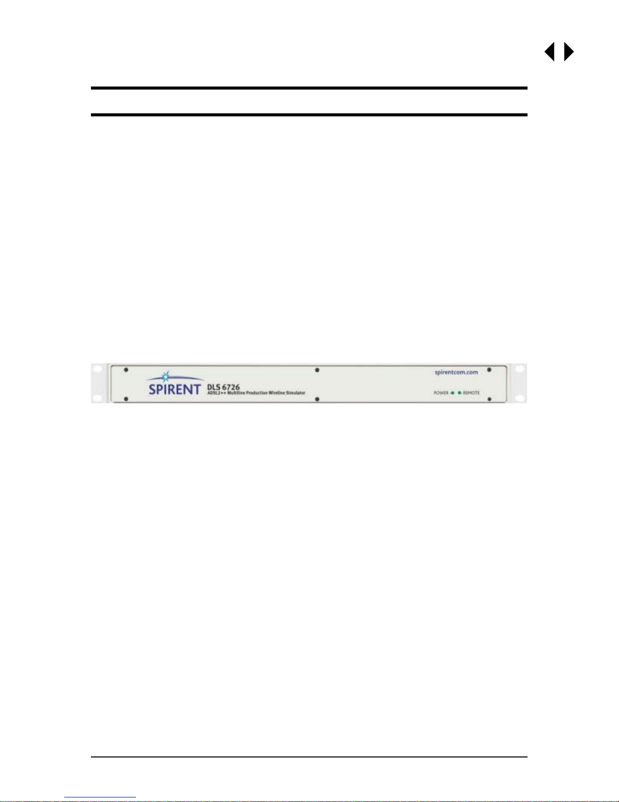
The DLS 6700 ADSL2++ Multi-line Production Wireline Simulator has been designed
to meet the needs of very high volume manufacturers of ADSL2++ bandwidth access
products (DC to 4.5 MHz). The DLS 6700 is used to ensure xDSL copper access products perform correctly before they leave the production floor. The DLS 6700 achieves
a low cost per port by offering 8, 12 or 18 port configurations in a 1 U rack mountable
chassis.
1.2 About the DLS 6700 ADSL2++ Wireline Simulator
The DLS 6700 ADSL2++ Multi-line Production Wireline Simulator simulates the insertion and return loss of a twisted copper cable, sometimes called a wireline.
The “DLS 6700 Series” currently includes the DLS 6726 (26AWG), and will be referred
to as the “DLS 6700” within this document. Specifications for the DLS 6726 have
been derived from North American (ANSI) standards.
Figure 1.1 DLS 6700 ADSL2++ Multi-line Production Wireline Simulator
The DLS 6700 ADSL2++ Wireline Simulator simulates 26 AWG cable for ADSL2++/
ADSL2+/ADSL2/ADSL production and verification testing. It has a reach of up to 24
kft in 1,000 ft increments, and a bandwidth of DC to 4.5 MHz. The unit is fully bidirectional, with all cable characteristics being accurately simulated using passive
components.
The DLS 6700 can simulate up to 18 wirelines per unit. The simulated wireline
lengths are controlled remotely via an RS-232 port.
There are two software methods for controlling the wireline simulator: you can use
the GUI which ships with the DLS 6700, or you can write custom, script-based software to operate your DLS 6700-based test system.
The DLS 6700 Software configures and controls the DLS 6700 ADSL2++ Wireline
Simulator remotely through the RS-232 interface. This software runs on any
Windows
computer.
One or more wireline simulators can be integrated into a larger test system, limited
by the number of COM ports available on the controlling computer. The configuration
software that ships with the DLS 6700 can access up to 16 com ports.
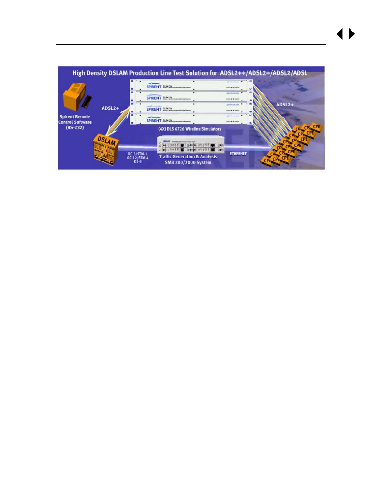
Figure 1.2 illustrates an example of a typical test setup using the DLS 6700 ADSL2++
Wireline Simulator.
TM
98, NT 4.0 with service pack 4.0 and up, or WindowsTM 2000 compatible
Spirent Communications 7104000557 Page 1-1
Page 6
DLS 6700 Operating Manual
Figure 1.2 Example Test System Setup
1.3 About this Manual
Read Chapter 2 "GETTING STARTED" thoroughly before powering up the DLS 6700
ADSL2++ Wireline Simulator.
This manual provides information about the various aspects of the wireline simulator,
such as loop configurations, remote control, warranty, specifications and contact
information.
The configuration software that shi ps wi th the DLS 6700 prov ides y ou wit h full control
over the characteristics of each DLS 6700 simulated loop.
We recommend that you develop your own scripts based on the type of automated
testing that best suits your products.
The common and device specific commands sets used to control the DLS 6700 are
fully explained in Chapter 4 "REMOTE CONTROL".
If you have any questions after reading this manual, please contact your Spirent
Communications sales representative or a member of the Customer Service team.
Please find contact information in Chapter 7 "CUSTOMER SUPPORT" of this manual.
Page 1-2 7104000557 Spirent Communications
Page 7

DLS 6700 Operating Manual
2. GETTING STARTED
This chapter provides basic instructions on the setup of a DLS 6700 ADSL2++ Wireline Simulator.
2.1 Receiving and Unpacking the Unit
Each DLS 6700 chassis has been shipped in a reinforced shipping container. Please
retain this container in case you need to ship the wireline simulator to another location or for repair. The DLS 6700 system contains the following:
• DLS 6700 Series chassis
• 1 AC to DC wall plug-in adapter
• 1 RS–232C inter-connection cable
• 1 DLS 6700 CD (software and related documents)
• 1 Operating Manual on CD
Check that you have received all the items on the list and report any discrepancies to
Spirent Communications. See Chapter 9 "SHIPPING THE UNIT" for information.
2.2 Setup Overview
To test:
1) Connect the power cord on the back of the DLS 6700 chassis and switch the
power on.
2) Connect the serial cable from the control computer to the back of the
DLS
6700.
3) Connect digital subscriber line access multiplexer (DSLAM) equipment to one
of the “Output” ports at the back of the DLS
4) Connect customer premise equipment (CPE) equipment to the corresponding
“Input” port at the back of the DLS
5) Start the DLS 6700 Software.
6) Connect the control software to the DLS 6700. From the list of available serial
ports on your computer (listed in the “Interfaces and Identification” panel of
the main window), choose the one attached to the DLS 6700 you want to con
trol. Press the Start Online button. This will open the DLS 6700 control window, allowing you to adjust the length of each wire line.
7) Adjust the line lengths for the test loops.
8) Begin testing.
See the following sections for detailed information.
6700.
6700.
2.3 Cabling Requirements
-
Cabling, switches and other equipment are needed to connect the DSLAM, the loop
simulator, and the CPE. Cables should be kept as short as possible so minimum noise
is coupled into the cables. Recommended cables are the CAT5 UTP. Since the length is
typically short (e.g., 2 feet), this does not affect measurements.
Computer screen and power supplies radiate in ADSL frequency bands. This noise
may be generated by either internal or external power supplies. When the noise levels
Spirent Communications 7104000557 Page 2-1
Page 8
DLS 6700 Operating Manual
are greater than -140 dBm /Hz, they will limit the ADSL2++ performance and influence the test results. These devices should be placed at a distance from the test setup
or even switched off.
The interconnection wiring for the “Output” and “Input” Ports should be physically
separated as crosstalk can occur between cabling. Configure the cables so that they
are not touching and the cable connecting to the DSLAM and CPE are separated as
much as possible (at least 15 cm).
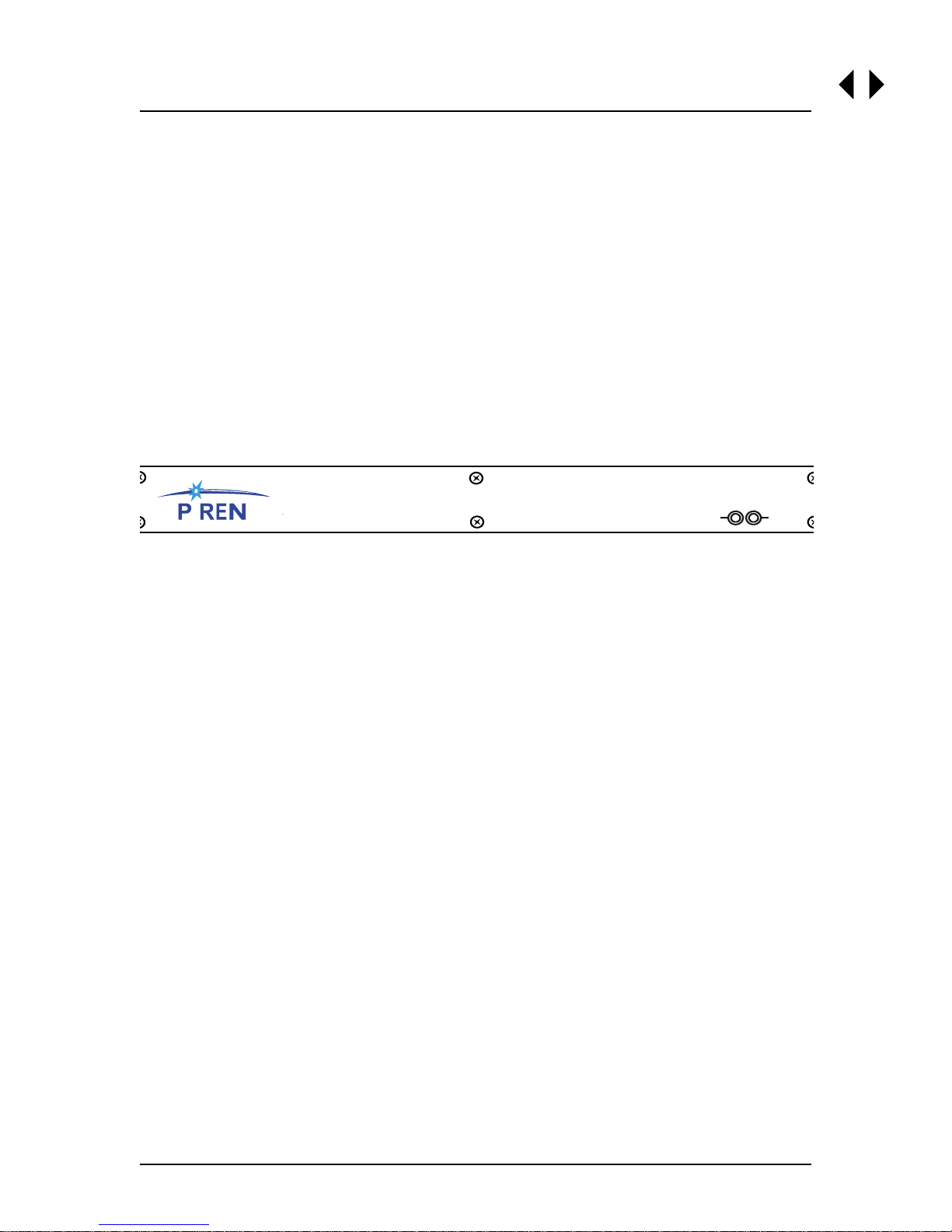
2.4 Front Panel Indicators
The DLS 6700 chassis has 2 LEDs which indicate the power and remote status.
The Power LED indicates when the unit is on, and doubles as an error status indica-
tor.
The Remote LED indicates when the DLS 6700 has received a command from the
control computer.
spirentcom.com
S I T
DLS 6700
.
Multiline Production Wireline Simulator
ADSL2++
POWER
REMOTE
Figure 2.1 DLS 6700 Front Panel
2.4.1 Reading Remote and Power Status
The POWER LED turns green when the power is turned on. The power LED blinks red
if it fails its self-test, or solid red if it detects an internal error.
The REMOTE LED is off after a power-up or a reset. When the unit receives the first
remote message, the REMOTE LED turns green if the command is valid or turns red if
an error is detected. An invalid command or an out -of-range value will cause an error.
The REMOTE LED stays red until the error flags are cleared (see the command *ESR?
for more details). When the REMOTE LED is red, the unit can still communicate as
normal, but you should investigate why the error occurred. Chapter 4 "REMOTE CON-
TROL" shows examples on how to read the ESR register, clear the error flags and
make the REMOTE LED green once error conditions have been resolved.
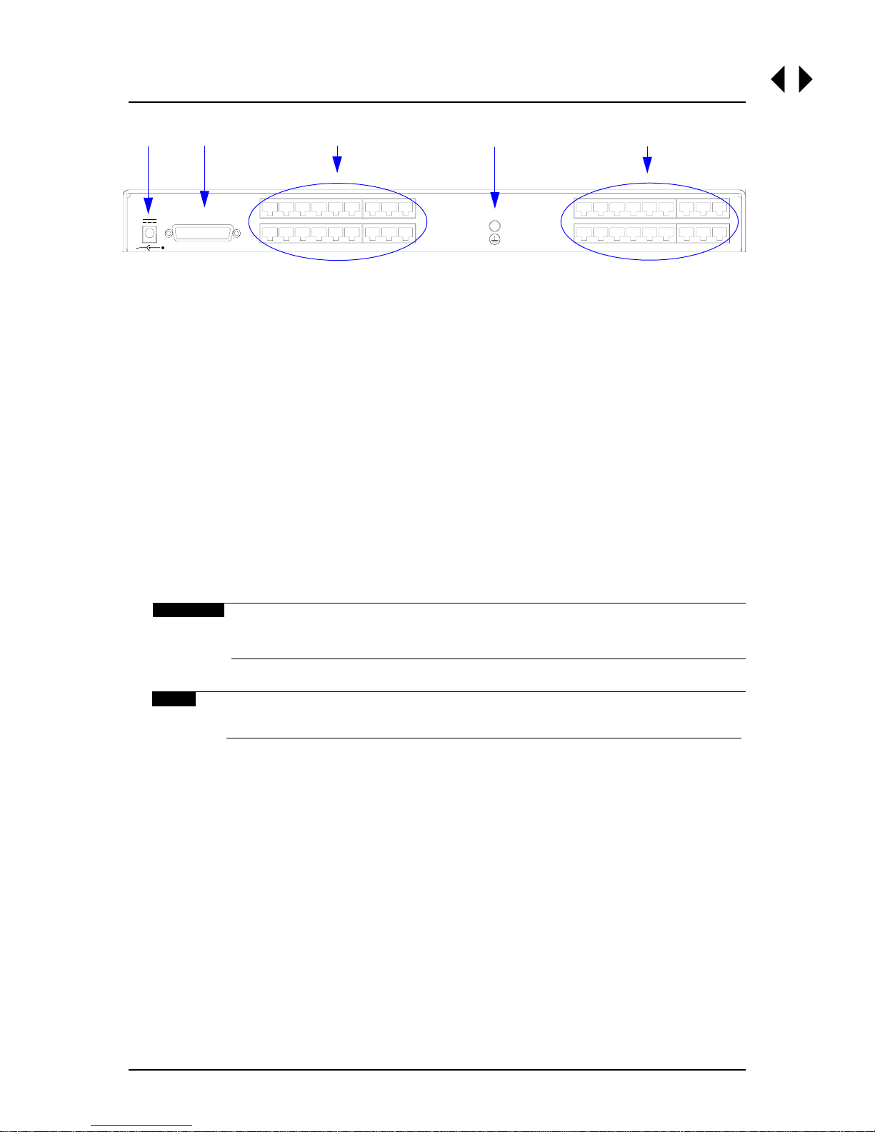
2.5 Rear Panel Connections
All connectors for the DLS 6700 are located on the rear panel (see Figure 2.2 "DLS
6700 Back Panel")
Page 2-2 7104000557 Spirent Communications
Page 9
Chapter 2: GETTING STARTED
1
Power
500 mA Max
12V DC
2
DB-25
3
18
9
10
OUTPUT
1
4
10
INPUT
1
5
18
9
Figure 2.2 DLS 6700 Back Panel
1) Power Input: Connect to an AC wall adapter power source
2) RS–232 (DCE) Serial Connector: Connect to a computer for remote control
3) RJ - 11 “Output” : (8, 12 or 18, depending on model) Connect to DUT (usually DSLAM devices).
4) Ground Connection: Connect to earth ground (optional)
5) RJ - 11 “Input”: (8, 12 or 18, depending on model) Connect to DUT (usually
CPE modems).
2.5.1 Connecting to Power
Connect the unit via the wall plug-in adapter (provided with the unit) at the back of
the unit to an AC power supply appropriate for your specific country. Please see Chap-
ter 10 "SPECIFICATIONS" for more details.
The power LED will turn on when the power is connected.
WARNING
Before operating the unit, please refer to Section 11.1.5 "Connections
to a Power Supply", to ensure that the correct AC/DC adapter is used.
NOTE
Please refer to Chapter 11 "SAFETY" for more details.
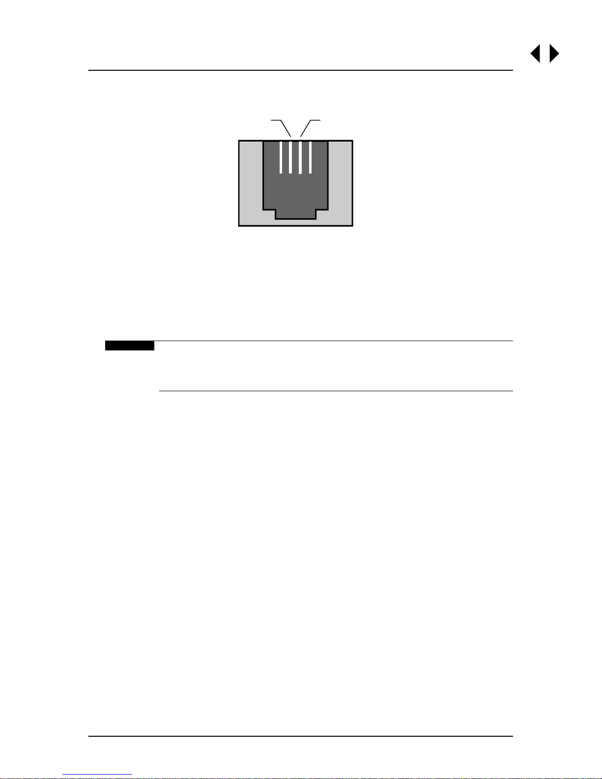
2.5.2 Connecting to Analog Devices with RJ-11 Connectors
In a typical setup the Telephone Exchange (Central Office) equipment would be connected to an “Output” Port, and the customer site equipment to the corresponding
“Input” Port of the DLS 6700 wireline simulator. The pinout of the RJ-11 female connector is shown in Figure 2.3.
Spirent Communications 7104000557 Page 2-3
Page 10
DLS 6700 Operating Manual
Balanced
Connection
Pin 2
Figure 2.3 RJ-11 Female Connector
The two center pins of the RJ-11 connector (pin 2, Tip; and pin 3, Ring) carry the
signal.
These connections are balanced. We recommend that these leads be shorter than 60
cm if you are using frequencies up to 4.5MHz. It is possible to use longer leads as the
frequency decreases.
WARNING
The maximum input to any DLS 6700 port must not exceed +/-100 V
or 100 mA between Tip and Ring. Exceeding these limits could damage
the unit.
Pin 3
2.6 DLS 6700 Remote Control
The DLS 6700 ADSL2++ Wireline Simulator is configured through its RS-232 serial
port. The reach (length) of each simulated wireline can be adjusted remotely using
configuration software.
You can use the included Spirent Communications’s GUI to configure the DLS 6700;
or you can develop your own custom configuration software using the DLS 6700 command set. This command set is covered in this manual (see Chapter 4 "REMOTE
CONTROL"), to assist you in developing custom software and scripts.
2.6.1 Connecting the Computer via the Serial Port (RS-232)
Connect one end of an RS-232 serial cable to the RS-232 connector located on the
back panel of the DLS 6700 chassis and the other end to a serial COM port connector
on the computer.
The DLS 6700 GUI supports up to 16 COM ports. It will automatically detect all serial
ports available on the control computer between COM1 and COM16. Only available
COM ports will be listed in the “Interfaces and Identification” panel of the main GUI
window. COM ports that exist on the control PC but are already open will not appear
in this list.
Page 2-4 7104000557 Spirent Communications
Page 11
DLS 6700 Operating Manual
3. DLS 6700 SOFTWARE
3.1 DLS 6700 Software
The DLS 6700 GUI provides you with an interactiv e interface to control the DLS 6700.
NOTE
TM
This software runs on any Windows
and up, or WindowsTM 2000 compatible computer.
3.1.1 Installation
To install the software, run SETUP.EXE from the installation CD if it does not start automatically when the CD is inserted. The user is prompted to specify the directory
where the software should be installed.
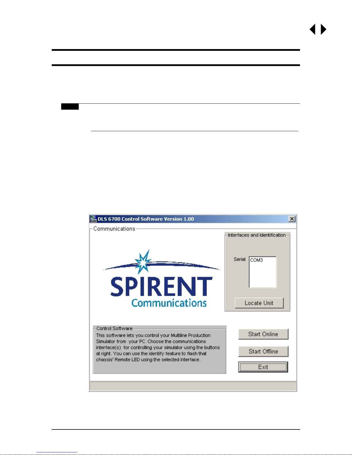
3.1.2 Starting the DLS 6700 Software
98, NT 4.0 with service pack 4.0
To start the DLS 6700 Control Software, click on the Start button in Windows, select
“Programs > Spirent Communications > DLS 6700”. The program will start and display
this screen:
Figure 3.1 DLS 6700 Control Software
Spirent Communications 7104000557 Page 3-1
Page 12
DLS 6700 Operating Manual
3.2 Communications Interface Selection
The DLS 6700 Control Software allows the user to specify a communications interface
for each DLS 6700 chassis to be controlled. Select the appropriate option button for
the desired COM port.
The DLS 6700 Control Software allows the user to choose the COM port which will be
used to control the DLS 6700. Select the COM port using the list box.
NOTE
The “Interfaces and Identification” panel lists only available COM ports.
If you wish to run multiple sessions of the GUI, you need to launch all
the sessions first before going online with any of the DLS 6700 units.
3.2.1 Identify Chassis
You can correlate which DLS 6700 chassis is attached to which COM port using the
“Identify Chassis” button.
Select a COM port from the “Interfaces and Identification” panel, and press the “Identify Chassis” button. The GUI will then atte m pt to f lash the Remote LED on the DLS
6700 unit using the selected COM port. During the identification, the “Stop Identification” button will appear, and all the other buttons will be disabled until the “Stop Identification” button is clicked.
3.2.2 Start Online
Once the correct COM Port is selected, click Start Online to use the program to control
your DLS 6700.
3.2.3 Start Offline
Click on “Start Offline” to start the program without controlling a DLS 6700 unit. This
is useful for viewing the features of the program where a DLS 6700 unit is not available.
3.3 Main Editing Grid
When the program starts, unless Start Offline is selected, the DLS 6700 Control Software reads the DLS 6700 on the specified interfaces to find out which lines are installed
in the unit. The software will determine the gauge, current length, minimum, maximum, and increment lengths, and present the information on the scr een.
The appearance of the Main Editing Grid will depend on what lines are installed in your
DLS 6700 unit. The range and the gauge of the line may be different from that shown
in the diagram.
3.3.1 Controlling the Line
The most direct way to control a DLS 6700 unit is to click on the Spin controls (up and
down arrows) to change the length of the line. This will “step” the length by the ap propriate increment or decrement. Values can also be entered in the Type In entry boxes.
Page 3-2 7104000557 Spirent Communications
Page 13

Chapter 3: DLS 6700 SOFTWARE
Regardless of the method chosen, the program will ensure that the final value is within
the range of the line and will round to the nearest correct step size.
3.3.2 Groups
The Grouping feature is a convenient way to set many lines at once. Select the lines
to be modified and then apply a length to the grouped lines.
Figure 3.2 DLS 6700 Main Editing Grid
To specify which lines are in the group, click the checkbox in the Grouped column for
each line that is to be grouped. Use the “Select All” and “Deselect All” buttons to set
and clear ALL the check boxes. Another button, Invert Selection, exchanges the
checked and cleared check boxes.
Spirent Communications 7104000557 Page 3-3
Page 14

DLS 6700 Operating Manual
Once the lines are selected, the length can be changed wit h either the Type-In box or
the Spin control. Click on the “Apply Length to Grouped Lines” button to send the
length to each of the selected lines.
NOTE
The length setting for the group length only gets applied when 'Apply
Length to Grouped Lines' is pressed, whereas the individual line length
is applied as soon as the value is changed.
3.4 Menu Selections
3.4.1 File
Load - Retrieves a previously stored file of DLS 6700 settings from disk.
Save - Stores the current settings of the DLS 6700 to a file on disk
Exit - Shuts down the program
3.4.2 Tools
Identify Units - Flashes the Remote LED on the appropriate unit. When Identify Unit is
clicked, the “Stop Identification” button will appear and it must be clicked before the
user can do anything else.
3.4.3 About
Shows information on the program such as version number.
Page 3-4 7104000557 Spirent Communications
Page 15

DLS 6700 Operating Manual
4. REMOTE CONTROL
The DLS 6700 is controlled via the RS-232 (serial) interface, allowing the integration
of the DLS 6700 into a larger test system. The DLS 6700 remote control is designed
with several standards in mind:
• The Common Commands follow IEEE 488.2.
• The Device Dependent Commands (see Section 4.4 "Device Dependent Com-
mands") are based upon the Standard Commands for Programmable Interfaces
(SCPI).
• The serial port physical interface follows the EIA RS-232 standard.
4.1 RS-232 Serial Interface
The DLS 6700 uses a female DB-25 or an RJ-45 connector, and is configured as a DCE
device. It can therefore be connected directly to a PC serial port.
The RS-232 standard is equivalent to the European V.24/V.28 standards. In this manual we use the term RS-232 to refer to both of these two standards. Generally, the
computer literature will use the words “serial”, “COM1” and “COM2” to refer to the
RS-232 interface. Note that the DLS 6700 cannot use the parallel port of a computer
(the female connector).
To use the RS-232 interface, connect your computer to the DLS 6700 and set the
computer to 9600 bps baud rate, no parity, 8 data bits per character, 1 stop bit and
RTS/CTS hardware flow control.
Do NOT use a null modem with a computer that has a standard COM port configured
as a DTE.
The DLS 6700 stops transmitting data when the R T S line is low , and restart s when the
RTS line is high. The DLS 6700 lowers the CTS and the DSR lines when it cannot
accept data, and raises them when it can. Note that the RTS line is not the usual
“Request To Send” as defined by the RS-232 standard. Y ou can lea v e the RTS line set,
and use only the CTS line.
Most serial port communication programs can be used to control the DLS 6700. Any
ASCII terminal emulator can be used. Configure it to add linefeeds and echo typed
characters locally.
4.1.1 Message Terminators
Messages sent to the DLS 6700 through the serial interface MUST be terminated with
the line feed character (ASCII <LF>, decimal 10, hex 0A). To ensure that no characters are left in the receive buffer of the DLS 6700 from a previous incomplete command, you can send the line feed character by itself before sending new commands.
Messages from the DLS 6700 are always terminated with a Line Feed character.
Note that some languages, such as BASIC, may automatically append a carriage
return and a line feed at the end of messages. The carriage return character is not a
valid terminator, and will invalidate the last command. To avoid this problem, you can
append a semi-colon after a string (after the quotes) when printing to the communication port. Another solution is to append a semi-colon at the end of the command
Spirent Communications 7104000557 Page 4-1
Page 16

DLS 6700 Operating Manual
itself (inside the quotes), so that the carriage return can be interpreted as a second
command, and be simply discarded by the DLS 6700. For example:
PRINT #1, “:set:channel:line 1”+CHR$(10); Preferred solution
OR
PRINT #1, “:set:channel:line 1;” Alternate solution
4.1.2 Example using the RS–232 Interface
To change the length of the line to 4000 ft, do the following:
1) transmit “:SET:CHAN:LINE 1, 4000 ft”
2) check that the REMOTE LED is still green; if it turns red, see Secti on Chapter 5
"TROUBLESHOOTING".
To send and receive messages with error checking follow these steps:
1) set all relevant enable bits (only done once)
2) send the message
3) read the answer until you receive LF (decimal 10, hex 0A)
4) check if an error occurred with the command *ESR?
For example, to get the identification message with the RS–232 interface, do the following:
1) transmit “*ESE 60” enable all the error bits (needed only once)
2) transmit “*IDN?” query the identification message
3) read the answer the messages are always terminated with LF
4) transmit “*ESR?” check if an error occurred
5) read the answer. If not 0, an error has occurred. See Event Status
Register (ESR) Section for description of the error(s)
4.2 Data Formats
The DLS 6700 adheres to th e IEEE 488.2 principle of Forgiving Listening and Precise
Talking.
The data formats supported by the DLS 6700 are:
Talking: a) <NR1> Numeric Response Data – Integer
b) Arbitrary ASCII Response Data
<NR1> is an implicit point representation of an integer.
Arbitrary ASCII Response Data is a generic character string without any delimiting
characters. It is usually used to send data in response to a query, such as with the
*IDN? command (see Section Section 4.5 "Common Command Set").
Listening: <NRf> Decimal Numeric Program Data
<NRf> is the Flexible Numeric Representation defined in the IEEE 488.2 standard
which can represent just about any number.
The DLS 6700 can accept data in the <NRf> format, which means that numbers can
be made of a combination of digits, signs, decimal point, exponent, multiplier, unit
and spaces. For example, any of the followin g is a valid representation for 4000 feet:
4kft, 4.0kft, 4000, .04e2k, 0.4 e4 ft, +4000. If a unit (i.e. ft, m, bps, etc.) is
appended to a number, that unit must be valid and not abbreviated. Note that the
period separates the decimal part of a number.
Page 4-2 7104000557 Spirent Communications
Page 17

Chapter 4: REMOTE CONTROL
4.3 Command Syntax
The DLS 6700 adheres to the IEEE 488.2 format for command syntax. As with the
Data Format, the principle is Forgiving Listening and Precise Talking.
Commands may take one of two forms: either a Device Dependent Command starting
with a colon (Section Section 4.3 "Command Syntax") or a Common Command starting with a star (Section Section 4.5 "Common Command Set"). Each type may be preceded by one or more spaces, and each must have one or more spaces between its
mnemonic and the data associated with it.
Common commands are preceded by the character “*”. Device Dependent commands
are preceded by a colon, with a colon separating each level of the command. Commands may be either in upper or lower case. Multiple commands may be concatenated by separating each command by semi-colons.
The following are some examples:
*RST
*RST;*WAI;:SET:CHANNEL:LINE 1, 4000 ft
*ESE 45; *SRE 16
Messages to the DLS 6700 must be terminated with a Line Feed character (ASCII
<LF>, decimal 10, hex 0A). Messages from the 6700 are always terminated with a
Line Feed character.
As defined in the SCPI specifications, a Device Dependent Command may be sent in
its short form or long form, in upper or lower case. The following commands are
therefore identical in operation:
:SET:CHANNEL:LINE 1, 4000 ft
:SET:C HAN:LINE 1, 4000 ft
Queries of the system follow the same format as the commands, except that the data
normally associated with a command is replaced by a question mark “?”. Following
receipt of such a command, the DLS 6700 will place the appropriate response in the
output queue, where the controller can read it. Examples are:
*IDN?
*ESE?;*SRE?
:SET:CHAN:LINE?
When a command does not begin with a colon, the DLS 6700 assumes that the command is at the same level as the previous command. For example, to set a line one
does NOT need to specify “:SYS:CAL” each time, as in:
:SYS:CAL:Date Dec 2001;Expiry Dec 2002
This shorter form is valid because both LINEs are at the same level.
4.4 Device Dependent Commands
As recommended by the SCPI consortium and to simplify programming of the various
Access Emulation Division simulators, the DLS 6700 uses the following tree structure:
:SETting
:CHANnel
Spirent Communications 7104000557 Page 4-3
Page 18

DLS 6700 Operating Manual
:LINE <Line Number>,<Length>
:SYStem
:CALibration
:DATe <date>
:EXPiry <date>
:SYStem
:COMMunicate
:SERial <date>
:ECHo <Off|ON>
Each section of the command may be sent in the full or the truncated form (indicated
in upper case). The command itself may be sent in upper or lower case form.
The DLS 6700 will round any number to the nearest number permitted by the resolution of the parameter.
Sections Section 4.2 "Data Formats" and Section 4.3 "Command Syntax" give more
information on the data format and the command syntax.
4.4.1 :SETting:CHANnel:LINE <Line Number>,<Length>
Select the reach (length) of the line, where <Line Number> is the line number is a
valid line according to the model of the unit (1 to 8, 1 to 12, or 1 to 18), and
<Length> is the length of the simulated line.
The length of the DLS 6726 can be adjusted to between 1 kft and 24,000 kft in 1,000
ft increments.
For example, to set the length of line 1 to 4,000 ft, send:
:SET:CHAN:LINE 1,4000 ft
To set the length of all the lines to 4,000 ft, send:
:SET:CHAN:LINE 1,4000 ft
The units of the length are optional, but they must be in “ft” if present for the
DLS 6726. For more details on the numeric format supported by the DLS 6700, see
Section 4.2 "Data Formats".
To query the length of line currently simulated by the DLS 6700 send:
:SET:CHAN:LINE 1?
The command will return the line number, the current length followed by the unit's
minimum length, the maximum length, length incremental step size, and the gauge
(26AWG). For example, if t he length of line 1 is 4 kft , and can vary from 1 to 24 kft in
1,000 ft steps, and is a 26 AWG gauge, the returned message will be:
1,4000 FT,0,24000,1000,26AWG
If there is no simulated line at the <Line Number>, then the DLS 6700 will return
“<Line NUMBER>,NONE”. For example:
17,NONE
4.4.2 :SYStem:Communicate:serial:echo <Off|On>
Set the echo off or on. For example:
:sys:comm:ser:echo on
Page 4-4 7104000557 Spirent Communications
Page 19

Chapter 4: REMOTE CONTROL
When the echo is on, the DLS 6700 will echo back all the characters sent to the unit
and display the prompt character “>”.
To query the echo state, send:
:sys:comm:ser:echo?
Note: New units leaving the Access Emulation Division facility will have the echo set
to off.
4.4.3 :SYStem:COMMunicate:SERial:PACE <pace>
Set the receiver and transmitter pace method (flow control) of the serial interface,
where <pace> is any of the following choices:
NONE | CTS | RTS/CTS | XON/XOFF | ALL
For example, to set the pace method to RTS/CTS, send:
:SYS:COMM:SER:PACE RTS/CTS
NOTE
The new pacing must be used immediately for any further serial
communication.
To query the current pacing method send:
:SYS:COMM:SER:PACE?
The command will return the pacing method as a string. For example, if the pacing
method is RTS/CTS, the returned message will be:
RTS/CTS
To simplify the setting of the serial interface, we used a slightly modified SCPI command set. The SCPI standard requires separate settings for the RTS/CTS flow control
and XOn/XOff pacing, and differentiates between the receive and the transmit sides.
The command set of the DLS 6700 combines the “:RTS” and the “XON” settings into
one “:PACE” command.
Note that the SCPI standard assumes a DTE configuration, whereas the DLS 6700 is
configured as a DCE port (thus no t requiring a Null Modem).
4.5 Common Command Set
As specified in the IEEE 488.2 standard, a number of common commands are
required to set up and control the standard functions of remote-controlled devices.
These common commands are as follows:
*CLS Clear Status Command
Type: Sta tus command
Function: Clears the Event Status Register (ESR). Clearing the Event Status R eg-
Spirent Communications 7104000557 Page 4-5
Page 20

DLS 6700 Operating Manual
ister will also clear ESB, the bit 5 of the Status Byte Register (STB). It
has no effect on the output queue (bit 4 of the STB).
*ESE <NRf> Event Status Enable
Type: Sta tus command
Function: Sets the Event Status Enable Register (ESER) using an integer value
from 0 to 255, representing a sum of the bits in the following bit map:
Bits 7 to 0 have values of 128, 64, 32, 16, 8, 4, 2 and 1, respectively.
For example, if bits 3 and 5 are set then the integer v alue is 40 (8+32).
On power-on, the register is cleared if the Power-on Status Clear bit is
1, or restored if the bit is 0 (see *PSC for more details).
*ESE? Event Status Enable Query
Type: Sta tus command
Function: An integer value between 0 and 255 representing the value of the
Event Status Enable Register (ESER) is placed in the output queue.
The possible values are described in the *ESE command section, and in
more detail in Section Section 4.6 "Status Reporting".
*ESR? Event Status Register Query
Type: Sta tus command
Function: An integer value between 0 and 255 representing the value of the
Event Status Register (ESR) is placed in the output queue. Once the
value is placed in the output queue, the register is cleared. The command will turn the REMOTE LED green if the LED w as red. The possible
values are described in the *ESE command section, and in more detail
in Section Section 4.6 "Status Reporting".
*IDN? Identification Query
Type: System command
Function: Returns the ID of the unit. Upon receiving this command the DLS 6700
will put the following string into the output queue:
SPIRENT COMM. INC,DLS 6700,<SN>,<Ver>
where: <SN> is the serial number of the unit
Page 4-6 7104000557 Spirent Communications
Page 21

Chapter 4: REMOTE CONTROL
<Ver> is the revision level of the control firmware (always 2 digits)
*OPC Operation Complete
Type: Synchronization command
Function:Indicates to the controller when the current operation is complete. This command will cause the DLS 6700 to set bit 0 in the Event
Status Register (ESR) when all pending operations are completed. The
bit is read with the *ESR? command, which also clear the bit. Communication can proceed as normal after this command.
*OPC? Operation Complete Query
Type: Synchronization command
Function:Indicates when the current operation is complete. This will
cause the DLS 6700 to put an ASCII 1 (decimal 49, hex 31) in the output queue when the current operation is complete. Communication can
proceed as normal after this command, but be prepared to receive the
“1” at any time. See Section 4.6.3 "DLS 6700 Synchronization".
*PSC <NRf>Power-on Status Clear
Type: Statu s and event command
Function: Indicates if the unit should clear the Service Request Enable Register
and the Standard Event Status Register at power-on. If 1 (or higher)
then all the enable registers are cleared at power-on, if 0 then all the
enable registers are restored from the non-volatile RAM at power-on.
The factory default is 1 (clear all the enable registers). Any change to
the “Power-on Status” is saved in non-volatile RAM, and is always
restored on power up.
*PSC? Power-on Status Clear Query
Type: Statu s and event command
Function: Return the Power-on Status Clear value. If 1 then all the enable regis-
ters are cleared at power-on, if 0 then all the enable registers are
restored from the non-volatile RAM at power-on. The factory default is
1 (clear all the enable registers).
*RST Reset
Type: Internal command
Function: IEEE 488.2 level 3 reset. This command will initialize the DLS 6700
with the bypass loop, and cancel any pend ing *OPC operation. It will
not affect the output buffer or other system settings of the unit. Note
that this is NOT equivalent to the power-up reset.
*SRE <NRf>Service Request Enable
Type: Sta tus command
Function: Sets the Service Request Enable Register (SRER). An integer value
indicates which service is enabled, with the following bit map:
Spirent Communications 7104000557 Page 4-7
Page 22

DLS 6700 Operating Manual
Bits 7 to 0 have values of 128, 64, 32, 16, 8, 4, 2 and 1, respectively.
For example, if bits 4 and 5 are set then the integer value is 48
(16+32).
On power-on, this register is cleared if the Power-on Status Clear bit is
1, or restored if the bit is 0 (see *PSC for more details).
*SRE? Service Request Enable Query
Type: Sta tus command
Function: An integer value representing the value of the Service Request Enable
Register is placed in the output queue. The possible values are listed in
the *SRE command section.
*STB? Status Byte Query
Type: Sta tus command
Function: The value of the Status Byte Register is put into the output queue. Con-
trary to the “*ESR?” command, this register is not cleared by reading
it. The register will be zero only when all its related structures are
cleared, namely the Event Status Register (ESR) and the output queue.
Bits 7 to 0 have values of 128, 64, 32, 16, 8, 4, 2 and 1, respectively.
For example, if bits 4 and 5 are set then the integer value is 48
(16+32).
*TST? Self-Test Query
Type: Internal command
Function: Returns the results of the self-test done at power up. The number
returned has the following bit map:
Page 4-8 7104000557 Spirent Communications
Page 23

Chapter 4: REMOTE CONTROL
Bits 7 to 0 have values of 128, 64, 32, 16, 8, 4, 2 and 1, respectively.
For example, if bits 3 and 5 are set then the integer v alue is 40 (8+32).
*WAI Wait to continue
Type: Synchronization command
Function: Used to delay execution of commands. The DLS 6700 will ensure that
all commands received before “*WAI” are completed before processing
any new commands. This means that all further communication with
the 6700 will be frozen until all pending operations are completed.
4.6 Status Reporting
There are two registers that record and report the system status, the Status Byte
Register (STB), and the Event Status Register (ESR).
For both registers there are three basic commands: one to read the register, one to
set the enabling bits, and one to read the enabling bits (<NRf> is the new value of the
register):
Status Byte Register Event Status Register
Read Register *STB? *ESR?
Set Enabling Bits *SRE <NRf> *ESE <NRf>
Read Enabling Bits *SRE? *ESE?
4.6.1 Status Byte Register (STB)
The bits of this register are mapped as follows:
bit 4: MAV (Message Available Bit)
Indicates that the Output Queue is not empty. If MAV goes high and is
enabled then MSS goes high.
bit 5: ESB (Event Status Bit)
It indicates that at least one bit of the Event Status R egist er is non ze ro
and enabled. If ESB goes high and is enabled then MSS goes high.
Spirent Communications 7104000557 Page 4-9
Page 24

DLS 6700 Operating Manual
bit 6: MSS/RQS (Master Summary Status/Request Service)
MSS is raised when either MAV or ESB are raised and enabled. MSS
summarizes all the status bits of the DLS 6700, as defined by the
IEEE 488.2 standard.
bits 7, 3, 2, 1, 0
These bits are not used by the DLS 6700.
4.6.2 Event Status Register (ESR)
The Event Status Register monitors events within the system and reports on those
enabled. It records transitory events as well. The DLS 6700 implements only the
IEEE 488.2 Standard Event Status Register (E SR). It is defined as:
bit 0 Operation Complete. This bit is set in response to the *OPC command when
the current operation is complete.
bit 1 Request Control. The DLS 6700 does not hav e an IEEE 488 bus , and so this bit
is always 0.
bit 2 Query Error. There was an attempt to read an empty output queue or there
was an output queue overflow (maximum output queue capacity is 75 bytes).
bit 3 Device Dependent Error. This error bit is set when the DLS 6700 receives a
command to set the length of a fixed loop. Only variable loops can have their
length changed.
bit 4 Execution Error. The data associated with a command was out of range.
bit 5 Command Error. Either a syntax error (order of command words) or a seman-
tic error (spelling of command words) has occurred. A GET (Group Execute
Trigger) or *TRG command will also set this bit.
bit 6 User Request. Indicates that the user has activated a Device Defined control
through the front panel. Not used, so this bit is always 0.
bit 7 Power on. This bit is set when the DLS 6700 is turned on. Sending *ESR?
clears the bit and it stays clear until the power is turned on again.
The setting of the Event Status Register can be read with the Event Status Register
query command (*ESR?). This will put the value of the register in the output queue,
AND will clear the register.
Page 4-10 7104000557 Spirent Communications
Page 25

Chapter 4: REMOTE CONTROL
4.6.3 DLS 6700 Synchronization
The program controlling the DLS 6700 can use three different commands to synchronize with the DLS 6700: *OPC, *OPC? and *WAI. The main differences are as follows:
Set Opera-
tion Com-
plete bit
when done
Return “1”
when oper-
ation com-
plete
*OPC Yes No
Raise SRQ
when oper-
ation com-
plete
1
Yes
Block
comm. with
the
DLS 6700
No Operation
Required
Enable
Bit(s)
Complete,
ESB
*OPC? No Yes
Yes
2
No MAV
*WAI No No No Yes none
1 if “Operation Complete” and ESB are enabled.
2 if MAV is enabled.
The main difference between OPC and WAI is that WAI will block any further communication with the DLS 6700 until all pending operations are completed.
The main difference between *OPC and *OPC? is that *OPC sets the “Operation Complete” bit, and *OPC? will return an ASCII “1” when all pending operations are completed.
Make sure that all the required enable bits are set.
When using *OPC or *OPC?, the program controlling the DLS 6700 can determine
when the operation is completed by waiting for S RQ, or by reading the status byte
with the serial poll or with *STB? (if corresponding bits are enabled).
If the program uses the *OPC? command and then sends more queries, the program
must be ready to receive the “1” concatenated to other responses at any time. When
using *WAI, the communication time out should be set long enough to avoid losing
data (the DLS 6700 needs approximately 2 seconds to set a loop).
Spirent Communications 7104000557 Page 4-11
Page 26

DLS 6700 Operating Manual
Page 4-12 7104000557 Spirent Communications
Page 27

DLS 6700 Operating Manual
5. TROUBLESHOOTING
1) The power LED flashes red:
At power up, the DLS 6700 performs a self-test. If this self-test fails, the power
LED flashes red. If this happens, consult the factory.
2) The power LED is orange:
If the DLS 6700 detects an internal error, it does a full system initialisation and
turns the power LED orange. If this happens, consult the factory.
3) The remote LED is off:
This is normal after both a power-up and a reset.
4) The remote LED is red:
The DLS 6700 received an invalid command from the computer. See Chapter 4
"REMOTE CONTROL" for more details.
5) The DLS 6700 program indicates a communication error:
• Check that no device (such as a mouse) is connected to the same serial
port as the DLS 6700.
• Check the cabling.
Spirent Communications 7104000557 Page 5-1
Page 28

DLS 6700 Operating Manual
Page 5-2 7104000557 Spirent Communications
Page 29

DLS 6700 Operating Manual
6. REFERENCES
• IEEE 488.2-1992, IEEE Standard Codes, Formats, Protocols, and Common Commands (The Institute of Electrical and Electronics Engineers, Inc. 345 East 47th
Street, New York, NY 10017-2394, USA)
• SCPI Standard Commands for Programmable Instruments, available from some
interface controller manufacturers (SCPI Consortium, 8380 Hercules Drive, Suite
P.S., La Mesa, CA 91942, Phone: (619) 697-8790, Fax: (619) 697-5955)
• ITU-T Recommendation G.996.1 (International Telecommunication Union, Place
des Nations, CH1211 Geneva 20, Switze rland)
• ITU-T Recommendation G.992.3 (International Telecommunication Union, Place
des Nations, CH1211 Geneva 20, Switze rland)
• ITU-T Draft Recommendation G.992.5, ADSL2plus specification (International Telecommunication Union, Place des Nations, CH1211 Geneva 20, Swit zerland)
• ANSI T1.601-1991, ISDN Basic Access Interface for use on Metallic Loops for
Application on the Network Side of the NT (American National Standards Institute,
11 West 42nd Street, New York, NY 10036, USA)
• ANSI T1.413-1995, Asymmetric Digital Subscriber Line (ADSL) Metallic Interface,
and ANSI T1.413 Issue 2 (American National Standards Institute, 11 West 42nd
Street, New York, NY 10036, USA)
• Belcore PUB 62310, Digital Data System Channel Interface Specification. September 1983.
• ITU-T G.991.2 Annex A (G.shdsl Annex A) (International Telecommunication
Union (ITU) Place des Nations CH-1211 Geneva 20 Switzerland, Tel: +41 22 730
511, Fax: +41 22 733 7256).
Spirent Communications 7104000557 Page 6-1
Page 30

DLS 6700 Operating Manual
Page 6-2 7104000557 Spirent Communications
Page 31

DLS 6700 Operating Manual
7. CUSTOMER SUPPORT
7.1 Customer Service Contact Information
For all North American customers, please direct any questions or concerns regarding
the operation of a purchased unit, to the Spirent Communications Customer Service
team by one of the following methods:
Direct Line: 613-592-7301
Toll free at: 800-465-1796
Fax at: 613-592-0522
E-mail at: ae.service@spirentcom.com.
All other customers should check the ae.spirentcom.com web site for the contact
information of the nearest Customer Service center or contact the main Spirent Communications service center for assistance (contact information is listed above).
For product information and updates, please visit the Spirent Communications web
site at:
https://ae.spirentcom.com
For product manuals, software updates and more information, please visit the customer extranet at:
http://ae.spirentcom.com/secure/
Passwords for the extranet can be requested at:
http://ae.spirentcom.com/Customer_care/needlogin.htm
7.2 Protecting Your Investment
Spirent Communications is committed to providin g the highest quality products and
customer support possible. An annual calibration is required to ensure that your unit
is operating properly.
Spirent Communications is pleased to offer two cost effective optional service programs. Each of these programs is designed to improve the ease and efficiency of
servicing Spirent Communications test equipment.
7.3 Extended Warranty
Spirent Communications' Extended Warranty gives two years in addition to the
original one-year manufacturer’s warranty. Under the warranty agreement, Spirent
Communications repairs any covered product that needs service during the warranty
period. At the time of repair, any required firm ware and/or software upgrades are
installed free of charge and if required as part of the repair, the unit receives a
complete calibration. Spirent Communications also provides return shipment of any
unit covered under warranty at Spirent Communications’s cost.
The Extended Warranty gives:
Spirent Communications 7104000557 Page 7-1
Page 32

DLS 6700 Operating Manual
• Extension of the original one-year limited warranty by two years (giving a total
warranty covera ge of three years).
• Required firm ware and software upgrades installed fr ee at time of repair.
• If required because of a repair, free calibration due to repair during the coverage
period.
• Prepaid, return shipment of repaired products worldwide.
Spirent Communications' Extended Warranty can be purchased at any time up until
the expiration of the original one-year manufacturer's warranty.
7.4 Three-Year Calibration Agreement
Spirent Communications’ three-year calibration agreement gives the opportunity to
invest in a yearly calib ration fo r three years at a significant cost saving, ens uring
optimum product performance.
Specific Spirent Communications products are shipped with a National Institute of
Standards and Technology (N.I.S.T.) traceable calibration that expires one year from
the original ship date. With ISO-9000 and other manufacturer specific metrology
requirements, timely calibrations become critical to your operations. Spirent
Communications sends out an e-mail reminder when the next calibration is due. A
report containing all calibration data is shipped with the product.
The Spirent Communications’s three-year calibration agreement gives:
• Three yearly N.I.S.T traceable calibrations (one per year).
• Notifi c a t ion fr om S p irent Communications when calibration is due.
• Calibration data report.
• Prepaid return shipment of calibrated unit worldwide.
• The Spirent Communications’ three-year calibration agreement may be purchased
at any time.
Please contact Spirent Communications Customer Service for more information on
these programs, or visit us on the web at ae.spirentcom.com.
Page 7-2 7104000557 Spirent Communications
Page 33

DLS 6700 Operating Manual
8. WARRANTY
Spirent Communications warrants all equipment bearing its nameplate to be free from
defects in workmanship and materials, during normal use and service, for a period of
twelve (12) months from the date of shipment.
In the event that a defect in any suc h eq uipm ent arise s wi thin the warranty period, it
shall be the responsibility of the customer to return the equipment by prepaid transportation to a Spirent Communications service center prior to the expiration of the
warranty period for the purpose of allowing Spir ent Communications to inspect and
repair the equipment.
If inspection by Spirent Communicati ons discloses a defect in workmanship or material it shall, at its option, repair or replace the equipment without cost to the customer
and return it to the customer by the least expensive mode of transportation, the cost
of which shall be prepaid by Spirent Communications.
In no event shall this warranty apply to equipment which has been modified without
the written authorization of Spirent Communications, or which has been subjected to
abuse, neglect, accident or improper application. If inspection by Spi rent Communications discloses that the repairs required are not covered under this warranty, the regular repair charges shall apply to any repairs made to the equipment.
For international customers, please contact your local Spirent Communications sales
representative or check the ae.spirentcom.com web site for the contact information
of the nearest service center.
In North America, if warranty service becomes necessary, the customer must contact
Spirent Communications to obtain a return authorization number and shipping
instructions:
Spirent Communications
750 Palladium Drive
Ottawa, Ontario, Canada
K2V 1C7
Customer Service Direct Line: 613-592-7301
Fax: 613-592-0522
Toll Free: 1-800-465-1796
ae.service@spirentcom.com
This warranty constitutes the only warranty applicable to the equipment sold by
Spirent Communications, and no other warranty or condition, statutory or otherwise,
expressed or implied, shall be imposed upon Spirent Communications nor shall any
representation made by any person, including a representation by a re pr es entat ive or
agent of Spirent Communications, be effective to extend the warranty coverage provided herein.
In no event (including, but not limited to the negligence of Spirent Communications,
its agents or employees) shall Spirent Communications be liable for special consequential damages or damages arising from the loss of use of the equipment, and on
the expiration of the warranty period all liability of Spirent Communications whatsoever in connection with the equipment shall terminate.
Spirent Communications 7104000557 Page 8-1
Page 34

DLS 6700 Operating Manual
Page 8-2 7104000557 Spirent Communications
Page 35

DLS 6700 Operating Manual
9. SHIPPING THE UNIT
To prepare the unit for shipment, turn the power off, disconnect all cables (including
the power cable) and pack the simulators in their original cartons. Do not place any
cables or accessories directly against the front panel as this may scratch the surface
of the unit. It is highly recommended t hat all shipme nts are marked with labels ind icating that the contents are fragile.
If sending a unit back to the factory, ensure that the Return Material Authorization
(RMA) number given by the Spirent Communications Customer Service department is
shown on the outside.
The RMA number is mandatory and must be obtained from a Spirent Communications
Customer Service center before shipping the unit (see Section 7 "CUSTOMER SUPPORT" for details on how to contact the nearest Spirent Communications Customer
Service center).
Spirent Communications 7104000557 Page 9-1
Page 36

DLS 6700 Operating Manual
Page 9-2 7104000557 Spirent Communications
Page 37

DLS 6700 Operating Manual
10. SPECIFICATIONS
10.1 General
Type of Wire: DLS 6726:26AWG as per ANSI T1.417
Variable range: DLS 6726:0-24,000 ft in 1000 ft increments.
Bandwidth: DC to 4.5 MHz
DC Rating: 100 V
Attenuation:
(Insertion Loss)
Impedance: ±10% (20 kHz – 4.5 MHz)
Control: Remote via RS-232 port
Connections: RJ-11
MAE < 1 dB (20 kHz – 4.5 MHz) Typically simulation vs.
theory
10.2 Environmental
Operating
Temperature:
Storage
Temperature:
Cable Reference
Temperature:
Humidity: 90% non-condensing max.
50ºF to 104ºF (+10ºC to +40ºC)
-4ºF to 158ºF (-20ºC to +70ºC)
72ºF (22ºC)
10.3 Mechanical
Chassis Weight: 10 lbs/ 4.5 kg per chassis
Dimensions: 1.75” x 17” x 15” (44 mm x 423 mm x 384 mm)
NOTE
Includes rack mount brackets (factory installed, removable).
Spirent Communications 7104000557 Page 10-1
(H x W x D) 1U height
Page 38

DLS 6700 Operating Manual
10.4 Carton Contents:
1) DLS 6700 ADSL2++ Wireline Simulator
2) AC to DC Wall Plug-in Adapter
3) RS–232C Cable
4) Control Software for Windows 98/NT/2000 operating systems
Page 10-2 7104000557 Spirent Communications
Page 39

DLS 6700 Operating Manual
11. SAFETY
11.1 Information
11.1.1 Protective Isolation
The DLS 6700 is isolated from hazardous AC line voltages by the supplied AC/DC
adapter. If the AC/DC adapter comes with a protective earth terminal, never wilfully
interrupt this connection.
11.1.2 Before Operating the Unit
• Inspect the equipment for any signs of damage, and read this manual thoroughly.
• Become familiar with all safety symbols and instructions in this manual to ensure
that the equipment is used and maintained safely.
11.1.3 Power Supply Requirements
AC Power: 100-240 VAC (±10%) 50/60 Hz
DC Power: DC used by the unit must be between 8.5 and 12 V. Note that the
polarity of the DC Plug is: The inner conductor is positive (+) and the
outer conductor is negative (-) . See sym bols in th e Safety section. The
maximum current taken is 400 mA.
11.1.4 Fuse Configuration
There are no fuses used in the unit. A non-replaceable thermal fuse is used in the
supplied AC/DC adapter.
11.1.5 Connections to a Power Supply
In accordance with international safety standards, the unit uses an approved AC/DC
adapter.
AC Power: 100-240 VAC (±10%) 50/60 Hz with with supplied adapter.
DC Power: DC used by the unit must be between 8.5 and 12 V. Note that the
polarity of the DC Plug is: The inner conductor is positive (+) and the
outer conductor is negative (-) . See sym bols in th e Safety section. The
maximum current taken is 400 mA.
11.1.6 Operating Environment
To prevent potential fire or shock hazard, do not expose the equipment to any source
of excessive moisture.
Spirent Communications 7104000557 Page 11-1
Page 40

DLS 6700 Operating Manual
11.1.7 Class of Equipment
The unit consists of an exposed metal chassis that is connected directly to earth via
the protective grounding conductor. in accordance with the HARMONIZED EUROPEAN
STANDARD EN 61010-1 1993, it is classified as a Safety Class 1 equipment.
WARNING
This is a Class A product. In a domestic environment this product may
cause radio interference in which case the user may be required to tak e
adequate measures.
11.2 Instructions
The following safety instructions must be observed whenever the unit is operated,
serviced or repaired. Failing to comply with any of these instructions or with any precaution or warning contained in the Operating Manual is in direct violation of the
standards of design, manufacture and intended use of the equipment.
NOTE
Spirent Communications assumes no liability for the customer’s failure to
comply with any of these requirements.
11.2.1 Before Operating the Unit
• Inspect the equipment for any signs of damage, and read the Operating Manual
thoroughly.
• Install the equipment as specified in the relevant section of this manual.
• Ensure that the equipment and any devices or cords connected to it are properly
grounded.
11.2.2 Operating the Unit
• Do not operate the equipment when its covers o r panels have been removed.
• Do not operate equipment if an interruption to the protective grounding is suspected. Ensure that the instrument remains inoperative.
• Unless absolutely necessary, do not attempt to adjust or perform any maintenance or repair procedure when the equipment is opened and connected to a
power source at the same time. Any such procedure should only be performed by
qualified service professional.
• Disconnect the power supply cord from the equipment before adding or removing
any components.
• Operating the equipment in the presence of flammable gases or fumes is
extremely hazardous.
• Do not perform any operating or maintenance procedure that is not described in
the Operating and Reference Manual.
• Some of the equipment’s capacitors may be charged even when the equipment is
not connected the power source.
11.3 Symbols
Page 11-2 7104000557 Spirent Communications
Page 41

Chapter 11: SAFETY
When any of these symbols appear on the unit, this is their meaning:
EQUIPOTENTIALITY–FUNCTIONAL
EARTH TERMINAL
PROTECTIVE GROUNDING
CONDUCTOR TERMINAL
CAUTION - REFER TO ACCOMPANYING DOCUMENTS
Spirent Communications 7104000557 Page 11-3
Page 42

DLS 6700 Operating Manual
Page 11-4 7104000557 Spirent Communications
Page 43

Appendix A "MEASUREMENTS AND TEST RESULTS"
Appendix A MEASUREMENTS AND TEST RESULTS
A.1 Measurement of the DLS 6700
When measuring the insertion loss of a bala nc ed line or lin e sim ula tor t hrough out th e
frequency domain, the following method is recommended:
Figure A.1 Electrical characteristics measurements
In Figure A.1, Rg, R
The balanced winding of the balun must be 100 Ω for 24AWG or 26AWG (North Hills
0301BB) or 135 Ohm for TP100 (North Hills 0312BB), in order to match the reference
impedance indicated in t he standards. Th e center tap on the balanced side is usually
connected to the shielding of the balun through one of the mounting screws.
The transmitter and receiver could be the tr ansmitting and receiving sections of a network analyzer.
Transformers and cables introduce errors of attenuation and phase. For accurate
measurements, first perform calibration (normalization) by replacing the simulator
with a direct connection.
WARNING
The use of unbalanced signals through the DLS 6700 will usually yield
incorrect measurements.
and the coax cables match the unbalanced winding of the balun.
L
Spirent Communications 7104000557 Page A-1
Page 44

DLS 6700 Operating Manual
A.2 Common Errors
There are three common errors:
• Coupling between input and output via the two transformers. When trying to
measure attenuations of 60 dB or so, approximately 1/1000 of th e input voltage,
or 1/1000000 of the input power is present on the output. It is very easy for
transformers - or even wires - placed close to each other to couple together far
more than this. Take care to keep inputs and outputs separate.
• The use of a high impedance measuring device with no load from tip to ring at the
receive end. This results in reflections due to a bad mismatch at the end of the
line, and leads to very peculiar response curves.
• Ground injected directly onto the tip or ring of the wireline simulator. This almost
always leads to a very noisy spectrum, with high background noise levels and
often harmonically related spectrum “spikes”.
A.3 Typical Attenuation Characteristics
0
-20
-40
Atten uation
-60
-80
0.01.02.03.04.05.0
Figure A3.1 DLS 6700 - Attenuation at 2 kft, 4 kft and 6 kft
Attenuation Char acteristics
Theory
Measured
2 kft
4 kft
6 kft
Frequency (MH z)
Page A-2 7104000557 Spirent Communications
Page 45

-10
-20
-30
-40
-50
Attenuation
-60
Appendix A "MEASUREMENTS AND TEST RESULTS"
Attenuat i on Char ac t er isti cs
Theory
Measured
-70
12 kft14 kft
10 kft
8 kft
-80
0.0 1.0 2.0
Frequency (MHz)
Figure A3.2 DLS 6700 - Attenuation at 8 kft, 10 kft, 12 kft and 14 kft
Attenuat i on Char ac t er isti cs
-30
Theory
Measured
-40
-50
-60
Attenuation
-70
-80
0.0 0.1 0.2 0.3 0.4 0.5
Figure A3.3 DLS 6700 - Attenuation at 16 kft, 18 kft, 20 kft and 24 kft
Spirent Communications 7104000557 Page A-3
24 kft
16 kft18 kft20 kft
Frequency (MHz)
Page 46

DLS 6700 Operating Manual
Page A-4 7104000557 Spirent Communications
Page 47

Appendix B "BACKGROUND NOISE MEASUREMENTS"
Appendix B BACKGROUND NOISE MEASUREMENTS
Background noise measurements for the wireline simulator are performed with a
spectrum analyzer, in this case, an Agilent 4395A spectrum/network analyzer.
Input A is used in spectrum-noise mode and the results are displayed in power spectral density units, i.e. dBm/Hz.
The noise floor of the Agilent 4395A with an input attenuator of 0 dB and resolution
BW=30 kHz (input A not connected) is illustrated in the graph below:
F
i
g
u
r
e
1
7
–
H
P
4
3
9
Figure B.1 HP 4395A Noise Floor
Figure B.1 demonstrates the Agilent 4395A spectrum/network analyzer’s Noise Floor
over a Bandwidth of 0-30MHz. The graph shows that for frequencies up to 10 MHz,
the noise floor is about -144 dBm/Hz; for frequencies in the range 10-30 MHz, the
noise floor is about -151 dBm/Hz. Hence, when measuring noises with values close to
the noise floor of the analyzer itself, results are inaccurate in the sense that the analyzer’s noise adds to the noise of the device under test (DUT); the displayed result will
be worse than the real one.
In conclusion, the error introduced by the analyzer itself has to be taken into considerations when measuring noises with values close to -140 dBm/Hz.
Spirent Communications 7104000557 Page B-1
Page 48

DLS 6700 Operating Manual
Page B-2 7104000557 Spirent Communications
 Loading...