

Page 1

Operating Manual
DLS 400E3
ADSL (European) Wireline Simulator
Revision 2
March 2004
Page 2

Page 3

DLS 400E3 Operating Manual
Spirent Communications - Table of Contents Page 1
7104000537 03/04 - 2
Table of Contents
1. INTRODUCTION ............................................................................................. 1-1
1.1 About Spirent’s Involvement in Wireline Simulation ....................................... 1-1
1.2 About DLS 400E3 ADSL (European) Wireline Simulators .............................. 1-1
1.3 About the Test Setup .......................................................................................... 1-3
1.4 About this Manual ............................................................................................. 1-4
1.4.1 About Related Documentation and Products .............................................. 1-5
2. GETTING STARTED ...................................................................................... 2-1
2.1 Receiving and Unpacking the Unit .................................................................... 2-1
2.2 Setup Overview ................................................................................................. 2-1
2.3 Cabling Requirements ....................................................................................... 2-2
2.4 Front Panel Components and Connections ........................................................ 2-2
2.4.1 Reading Remote and Power Status ............................................................. 2-3
2.4.2 Connecting DLS 400E3 Chassis Together .................................................. 2-3
2.4.3 Connecting to Analog Devices with CF Connectors .................................. 2-3
2.4.4 Connecting to Analog Devices with RJ-45 Connectors (Adapters) ............ 2-3
2.5 Back Panel Components and Connections ........................................................ 2-4
2.5.5 Connecting to Power ................................................................................... 2-5
2.5.6 Injecting Noise in the System ...................................................................... 2-5
2.5.7 Connecting to a Windows Computer (for Remote Control) ........................ 2-5
2.5.7.1 Connecting the Computer via the IEEE 488 Port (GPIB) .............................. 2-5
2.5.7.2 Connecting the Computer via the Serial Port (RS-232) ................................. 2-6
3. DLS 400E3 CONTROL SOFTWARE ....................................................... 3-1
3.1 About the Software ............................................................................................ 3-1
3.1.1 Computer Hardware and Software Requirements ....................................... 3-1
3.2 Installing the Software ....................................................................................... 3-1
3.3 Accessing the Main Window ............................................................................. 3-2
3.4 Accessing the Control Window (s) .................................................................... 3-2
3.5 Configuring the DLS 400E3 Simulator ............................................................. 3-5
3.5.1 Identifying Simulator Connection ............................................................... 3-5
3.5.2 Bypassing or Reversing Loops .................................................................... 3-5
3.5.3 Setting the Relay Refresh Feature ............................................................... 3-5
3.5.4 Compensating Line Segment Lengths ......................................................... 3-6
3.5.5 Selecting the Test Loop ............................................................................... 3-7
3.5.6 Configuring Line Segments ......................................................................... 3-8
3.5.7 Micro Interruption Feature Overview ....................................................... 3-8
3.5.7.1 Setting the Micro Interruption Feature ........................................................ 3-9
3.5.8 Configuring Internal Noise Impairment Cards ......................................... 3-10
4. COMMON COMMAND SET FOR REMOTE CONTROL ........... 4-1
4.1 Generic IEEE 488 & RS-232 Controls .............................................................. 4-1
4.2 IEEE 488 Interface ............................................................................................ 4-1
4.2.1 IEEE 488.1 Interface functions supported .................................................. 4-1
4.2.2 The Service Request (SRQ) Line ................................................................. 4-1
4.2.3 Message Terminators .................................................................................. 4-2
4.2.4 Example using the IEEE 488 Interface ....................................................... 4-2
4.3 RS-232 Serial Interface ...................................................................................... 4-3
4.3.1 Message Terminators .................................................................................. 4-4
4.3.2 Example using the RS-232 Interface ........................................................... 4-4
4.4 Data Formats ...................................................................................................... 4-5
Page 4

DLS 400E3 Operating Manual
Table of Contents Page 2 - Spirent Communications
7104000537 03/04 -2
4.5 Command Syntax .............................................................................................. 4-5
4.6 Self-Test ............................................................................................................. 4-6
4.7 Common Command Set ..................................................................................... 4-7
4.8 Status Reporting ............................................................................................... 4-10
4.8.1 Status Byte Register (STB) ........................................................................ 4-10
4.8.1.1 Event Status Register (ESR) ..................................................................... 4-11
4.8.2 Host System Synchronization .................................................................... 4-11
5. DLS 400E3 LOOP DESCRIPTIONS FOR REMOTE CONTROL 5-1
5.1 DLS 400E3 Loop Configurations ...................................................................... 5-1
5.2 Reversing Loops ................................................................................................ 5-1
5.3 DLS 400E3 Fine Increment Wireline Card ....................................................... 5-1
5.4 Remote Control for Compensated Loops .......................................................... 5-1
6. DEVICE SPECIFIC COMMANDS FOR REMOTE CONTROL 6-1
6.1 Command Syntax .............................................................................................. 6-1
6.2 Wireline Settings ................................................................................................ 6-2
6.2.1 Example using the IEEE 488 Interface ....................................................... 6-5
6.2.2 Example using the RS–232 Interface .......................................................... 6-6
6.3 Wireline Simulator Bypass ................................................................................ 6-6
6.4 Setting the Relay Refresh and Micro-Interrupt Features ................................... 6-7
6.4.1 Synchronization of Commands .................................................................... 6-7
6.4.2 Sub-routines for Commands ........................................................................ 6-8
6.5 Resetting the DLS 400E3 .................................................................................. 6-9
7. REFERENCES ................................................................................................... 7-1
8. CUSTOMER SUPPORT ................................................................................ 8-1
8.1 Customer Service Contact Information ............................................................. 8-1
8.2 Protecting Your Investment ............................................................................... 8-1
9. WARRANTY ....................................................................................................... 9-1
10. SHIPPING THE UNIT ............................................................................... 10-1
11. SPECIFICATIONS ....................................................................................... 11-1
11.1 Wireline Simulator Specifications ................................................................. 11-1
11.2 Operating Conditions ..................................................................................... 11-2
12. SAFETY ............................................................................................................ 12-1
12.1 Information .................................................................................................... 12-1
12.1.1 Protective Grounding (Earthing) ............................................................ 12-1
12.1.2 Before Operating the Unit ....................................................................... 12-1
12.1.3 Power Supply Requirements ................................................................... 12-1
12.1.4 Fuse Configuration ................................................................................. 12-1
12.1.5 Operating Environment ........................................................................... 12-1
12.1.6 Class of Equipment ................................................................................. 12-1
12.2 Instructions .................................................................................................... 12-2
12.2.1 Before Operating the Unit ....................................................................... 12-2
12.2.2 Operating the Unit .................................................................................. 12-2
12.3 Symbols ......................................................................................................... 12-3
Page 5
DLS 400E3 Operating Manual
Spirent Communications - Page 1-1
7104000537 03/04 -2
1. INTRODUCTION
1.1 About Spirent’s Involvement in Wireline Simulation
Thank you for choosing Spirent Communications.
Spirent Communications has been in the wireline simulation business for over 15 years. Since the days of
the S2, Spirent Communications has designed many new simulators both to customers' specifications and to
conform to an ever-growing range of standards. By introducing the DLS 100 in 1985 we believe that we sold
the world's first truly wideband wireline simulator with the capability to successfully simulate attenuation,
characteristic impedance and delay.
The new specifications from ETSI, TS 101 388 and ITU-T ADSL2 (European) have new loop models and
noise requirements for ADSL testing in Europe. The DLS E3PKG covers the complete solution for wireline
simulation, noise generation and software to address these new standards.
Using the latest loop simulation technology the DLS 400E3 is the core of this solution. Available as a complete new system or as a simple upgrade to an existing DLS 400E2 the DLS 400E3 offers the highest accuracy for testing European ADSL/ADSL2 devices.
The complete DLS E3PKG solution from Spirent Communications combines the DLS 400E3 with the
DLS 5200E3 Noise Generation system, and can be used with the SmartBits SMB 200/2000 Data Generator/
Analyser. This solution allows accurate, consistent and repeatable testing from the initial design stage
through to deployment of ADSL devices complying with the latest specifications.
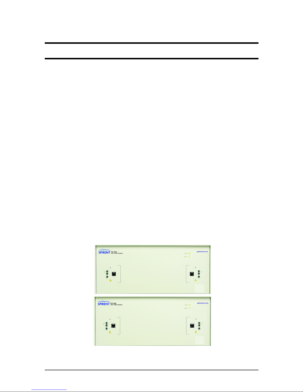
1.2 About DLS 400E3 ADSL (European) Wireline Simulators
The DLS 400E3 ADSL (European) Wireline Simulator shown in Figure 1.1 reproduces the AC and DC
characteristics of twisted pair copper telephony cable using passive circuitry (R, L & C), which means that
attenuation, complex impedance and velocity (propagation delay) of all wirelines are properly simulated.
The DLS 400E3 wireline simulator is based on a modular and open design that provides a high degree of
flexibility and scalability. It allows you to mix and match various gauges and lengths of wirelines in order to
configure the loop of choice. It can be set to provide many different configurations of these wirelines.
Figure 1.1 DLS 400E3 Wireline Simulator (chassis 1 and 2)
E3
E3
CHASSIS 2/2
CHASSIS 1/2
Page 6
DLS 400E3 Operating Manual
Page 1-2 - Spirent Communications
7104000537 03/04 -2
The simulator shown in Figure 1.1 is made up of two chassis (DLS 400E3 1/2 + DLS 400E3 2/2) that simulate
Loop # 1 to 8 and, provide two ports for external noise injection. The system offers the following addi-
tional features:
• micro-interrupt
• relay refresh
• simulates European line segments
• next generation backplane
• next generation compensation cards for optimal frequency response
If you already use a DLS 400E2 Wireline Simulator, there are upgrades available for DLS 400E3. Please
contact your local Spirent Communications sales representative for pricing. See Chapter 8 "CUSTOMER
SUPPORT"for contact information.
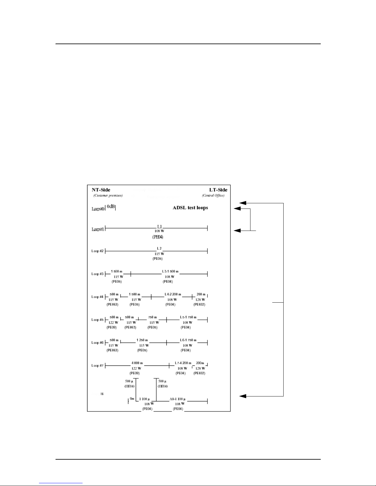
The DLS 400E3 ADSL (European) Wireline Simulator simulates all of the European test loops as per TR048 (0.4mm gauge type), TS 101 388, ETR 328 and WT-085. The applicable loop configurations shown in
Figure 1.2 are the same for the three standards. The only difference from standard to standard are the line
segment lengths for each loop.
Figure 1.2 TS 101 388 ADSL over ISDN Test Loops
TR - 048
TS 101 388
&
ETR 328
ETSI
WT - 085
Page 7

DLS 400E3 Operating Manual
Spirent Communications - Page 1-3
7104000537 03/04 -2
The DLS 400E3 Software runs under Windows® and allows you to control (over IEEE 488 or RS-232 interfaces) the DLS 400E3 wireline simulator with optionally associated internal DLS 5A01H impairment cards
or an external DLS 5200E3 Noise Generation system. The IEEE 488 and RS-232 interfaces allow the easy
integration of these wireline simulators into a larger test system. You can control the DLS 400E3 wireline
simulator with scripts using SCPI commands or use Spirents’ DLS 1200 library for Spirent Connect.
1.3 About the Test Setup
The DLS 400E3 includes the latest technology in wireline simulation hardware and software. A feature of
the DLS 400E3 is the integrated DLS 1310E3 Compensation Software, which ensures the simulator
achieves the highest accuracy and repeatability possible. Customers who have a DLS 400E2 can upgrade to
the DLS 400E3 system, which includes the additional test loops and software compensation package.
Spirent Communications has developed the “DLS 1310E3 Compensation Software”; a simple to use software based analysis tool that compares setup test results to expected values and provides wireline length
compensation data. This tool is recommended for use on a regular basis, prior to any extensive tests that
must be performed.
Real world noise has a dramatic impact on the performance of ADSL modems and DSLAMs. ETSI TS 101
388 has captured many of the worst-case scenarios and specified a set of crosstalk, RFI, impulse and white
noise test requirements.
In response to these requirements, Spirent has developed the DLS 5200E3 Noise Generation system. The
DLS 5200E3 Noise Generation System provides all of the impairments specified in TS 101 388 including
RFI (using the noise file from 5B13) and applies them as required, within accuracy requirements, in either
common or differential mode to the wireline. Other features include “design your own noise shape” capability for PSD noise files, a bandwidth from 12KHz to 12.5MHz, automation via Ethernet control and ETSI /
ANSI compliant crest factor.
For customers not concerned about common mode noise injection and less concerned with high accuracy,
the use of two DLS 5A01H noise impairment generators, together with noise files from the DLS 5A13.
Noise File CD-ROMs, will also allow for most TS 101 388 tests to be performed.
Using the unique capabilities of the 10/100 Ethernet and ATM SmartCards, SmartBits™ SMB 200/2000
allows for unparalleled end-to-end stability, frame loss, and latency measurements up to full wire rate.
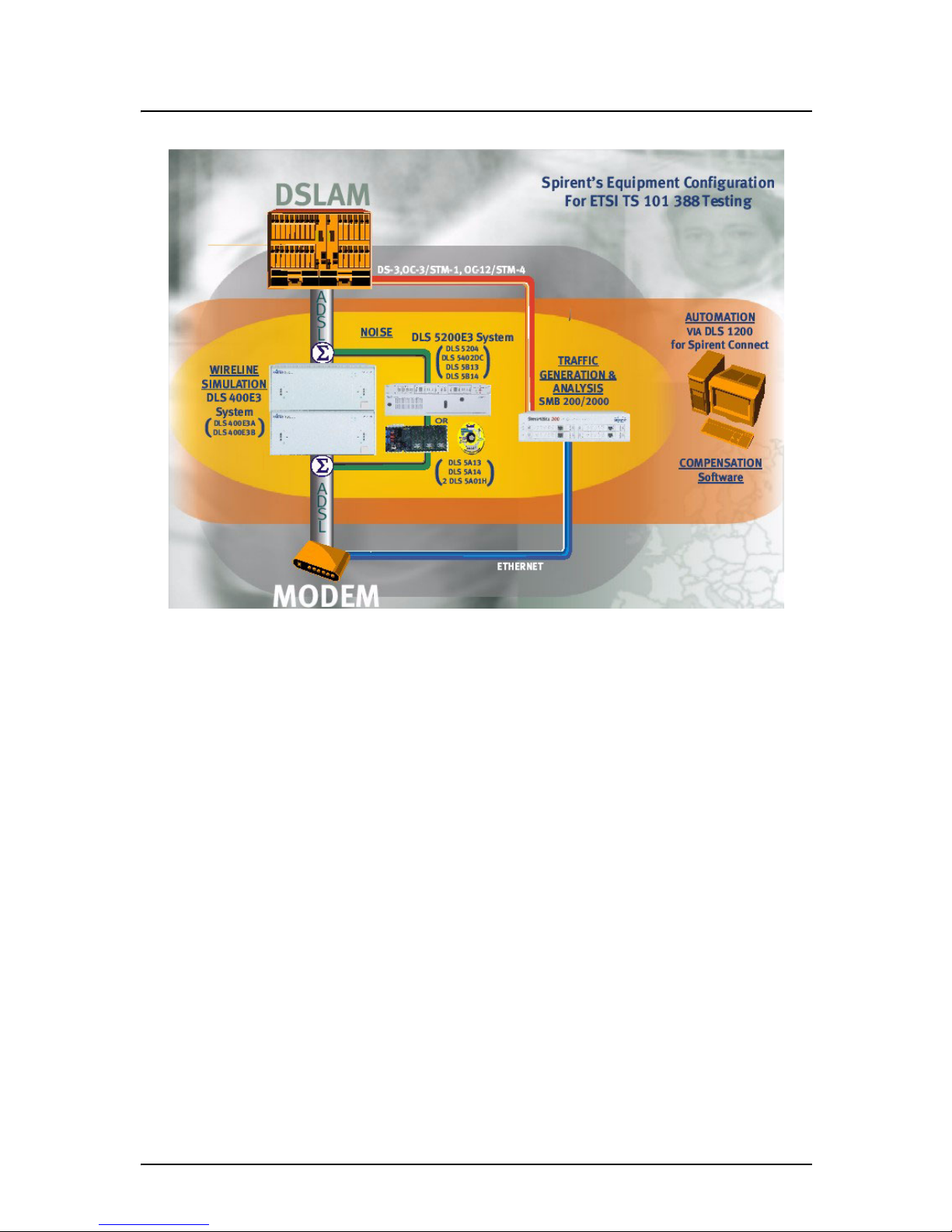
Figure 1.3 illustrates an example of a typical test setup using the DLS 400E3 wireline simulator.
Page 8
DLS 400E3 Operating Manual
Page 1-4 - Spirent Communications
7104000537 03/04 -2
Figure 1.3 Example Test System Setup
By using Spirent’s complete ETSI TS 101 388/TR-048 (.4mm gauge type)/ETR 328 solution to define and
deploy devices that meet performance and conformance standards, service providers will be able to offer the
next generation of services. For more information on compatible Spirent Communications products, see the
About Related Documentation and Products section of this chapter.
1.4 About this Manual
You should read Chapter 2 "GETTING STARTED" thoroughly before powering up the DLS 400E3 wireline
simulator. The remainder of this manual provides information about the various aspects of the wireline simulator, such as loop configurations, remote control, warranty, specifications and contact information.
We recommend you use our DLS 400E3 Software to configure and control the wireline simulator. However,
we detail common and device specific commands sets that can be sent to the wireline simulator’s control
module through the IEEE 488 or RS-232 interfaces, in Chapter 4 "COMMON COMMAND SET FOR
REMOTE CONTROL" and Chapter 6 "DEVICE SPECIFIC COMMANDS FOR REMOTE CONTROL".
If there are any questions after reading this manual, please contact your Spirent Communications sales representative or a member of the Customer Service team. Please find contact information in Chapter 8 "CUSTOMER SUPPORT" of this manual.
Page 9

DLS 400E3 Operating Manual
Spirent Communications - Page 1-5
7104000537 03/04 -2
1.4.1 About Related Documentation and Products
Existing customers can view and down load the following manuals from the Spirent extranet site:
https://ae.spirentcom.com/secure
• DLS 5200E3 Noise Generation System Operating Manual
• DLS 1200 Library for Spirent Connect
• SmartBits 200/2000 Installation Guide
For new customers, please contact Spirent Communications Customer Service about getting access to the
site. Apply for a password at https://ae.spirentcom.com/customer_care/needlogin.htm.
For the DLS 1310E3 Compensation Software you are provided with On-line Help. This is viewable only
once the software is installed (under the Help menu).
Page 10

DLS 400E3 Operating Manual
Page 1-6 - Spirent Communications
7104000537 03/04 -2
Page 11

DLS 400E3 Operating Manual
Spirent Communications - Page 2-1
7104000537 03/04 -2
2. GETTING STARTED
2.1 Receiving and Unpacking the Unit
Each DLS 400E3 chassis has been shipped in a reinforced shipping container. Please retain this container in
case you need to ship the wireline simulator to another location or for repair. The DLS 400E3 system contains the following:
• DLS 400E3 1/2 and DLS 400E3 2/2 chassis
• 1 power cord per chassis
• 2 extra fuses per chassis
• 1 RJ-45 chassis blue unsheilded twisted pair (UTP) connection cable
• 1 RS–232C interconnnection cable per chassis
• 1 IEEE 488 interconnection cable per chassis
• 2 CF–to–twin RJ–45 adaptors per chassis
• DLS 400E3 Control Software
• DLS 1310 E3 Compensation Software
• DLS 400E3 ADSL (European) Wireline Simulator Operating Manual
Check that you have received all the items on the list and report any discrepancies to Spirent Communications. See Chapter 10 "SHIPPING THE UNIT" for information.
2.2 Setup Overview
To te s t :
1) Connect the power cord to both chassis of the DLS 400E3 and switch the power on.
2) Ensure that both of the DLS 400E3 chassis have different IEEE addresses.
3) Connect a cable from the computer to chassis 1. If using IEEE 488 cable, connect a second IEEE
488 cable from chassis 1 to chassis 2. If using serial cable to both chassis, a serial port is required
on the PC to chassis 1 and chassis 2.
4) Connect your digital subscriber line access multiplexer (DSLAM) equipment to side A of chassis 1.
5) Connect side B of chassis 1 to side A of chassis 2 using the supplied blue UTP cable.
6) Connect your customer premise equipment (CPE) equipment to side B of chassis 2.
7) Start the DLS 400E3 Software.
8) Select the wireline simulator used (i.e. DLS 400E3) by selecting the “User Defined” selection in
the main window. You can also select “Detect Units”, as this allows the DLS 400E3 program to poll
for any connected devices over Serial or IEEE 488 interfaces.
9) Select “Connect to Units”.
10) Select the desired test loops via the drop-down menus.
11) Select the desired impairments if a external DLS 5200E3 noise generator or internal DLS 5A01H
noise card is installed.
12) Begin testing.
See the following sections for detailed information.
Page 12

DLS 400E3 Operating Manual
Page 2-2 - Spirent Communications
7104000537 03/04 -2
Note: If you re-arrange wireline cards, the DLS 400E3 Software will no longer detect the wireline simu-
lator as a DLS 400E3 but rather as a custom chassis.
2.3 Cabling Requirements
Cabling, switches and other equipment are needed to connect the DSLAM, the loop simulator, the noise generator and the ATU-R. Cables should be kept as short as possible so minimum noise is coupled into the
cables. Recommended cables are the CAT5 UTP. Since the length is typically short (e.g., 5 feet), this minimizes the effect.
Computer screen and power supplies radiate in ADSL frequency bands. This noise may be generated by
either internal or external power supplies. When the pick up noise levels are greater than -140 dBm /Hz, they
will limit the ADSL performance and influence the test results. These devices should be placed at a distance
from the test setup or even switched off.
The ATU-R and ATU-C and their wiring should be physically separated as crosstalk can occur between
cabling. Configure the cables so that they are not touching and the cable connecting to the DSLAM and CPE
are separated as much as possible (at least 15 cm).
To obtain the maximum accuracy, the cables, switches and any other equipment used in the link between the
DSLAM and the CPE should be contained within the compensation process described in the DLS 1310 E3
Compensation Software On-line Help.
2.4 Front Panel Components and Connections
The front panel looks the same for all the DLS 400E3 units. The front panel is used to connect devices under
test (DUTs) and read the power and remote status. Figure 2.1 displays the key components of the front panel.
.
Figure 2.1 DLS 400E3 Front Panel
DLS 400E3 Front Panel Components
1. Side A RJ-45 connector: used to connect a DUT
2. Side A balanced CF connector
1
: used to connect a DUT or a second chassis
3. Side B RJ-45 connector: used to connect a DUT
1. Note that Spirent Communications supplies a CF to RJ-45 adapter for both Side A and Side B CF
connectors.
Page 13
DLS 400E3 Operating Manual
Spirent Communications - Page 2-3
7104000537 03/04 -2
4. Side B balanced CF connector
1:
used to connect a DUT or a second chassis
5. Remote LED: indicates the remote status
6. Power LED: indicates the power status
2.4.1 Reading Remote and Power Status
Individual DLS 400E3 chassis have 2 LEDs which indicate the power and remote status.
The POWER LED turns green when the power is turned on. The power LED blinks red if it fails its self-test,
or yellow if it detects an internal error.
The REMOTE LED is off after a power-up or a reset. When the DLS 400E3 receives the first remote message, the REMOTE LED turns green if the command is valid or turns red if an error is detected. An invalid
command or an out-of-range value will cause an error. The REMOTE LED stays red until the error flags are
cleared (see the command *ESR? for more details). When the REMOTE LED is red, the unit can still communicate as normal, but you should investigate why the error occurred. Chapter 4 "COMMON COMMAND
SET FOR REMOTE CONTROL" shows examples on how to read the ESR register, clear the error flags and
make the REMOTE LED green once error conditions have been resolved.
2.4.2 Connecting DLS 400E3 Chassis Together
To simulate ETSI TS 101 388 line segments you need to connect two chassis together with a cable labelled
7102040514. Side B of unit 1connects to side A of unit 2. This one foot RJ-45 cable is provided as an accessory within the DLS 400E3 package. See Section 2.4.4 for RJ-45 connector details.
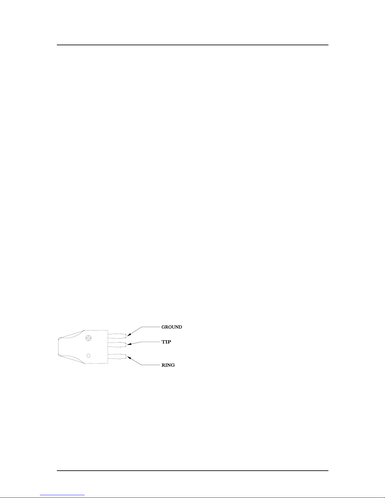
2.4.3 Connecting to Analog Devices with CF Connectors
The CF connector is a balanced 3-pin (ring, tip, ground) connector. It is possible to use banana plugs instead
of the CF connector, but note that the distance between the pins is not the 0.75" spacing used in North America.
The DLS 400E3 provides bi-directional wireline simulation.
In a typical setup the Telephone Exchange (Central Office) equipment would be connected to side A of the
DLS 400E3, and the customer site equipment to side B of the DLS 400E3. Either the RJ-45 or CF connectors on the front of the unit, or the connectors on the back may be used. Note that all the RJ-45 jacks and 3pin CF connectors on each side are balanced and connected in parallel.
A CF plug looks like the diagram at the left. There are 3
prongs spaced unevenly, as shown. You can use banana
plugs if the correctly spaced CF connector is not available.
These connections are balanced.
WARNING: The maximum input to the DLS 400E3 must not exceed -30 dBm between 50 Hz and 1
kHz. Exceeding these limits could damage the unit.
2.4.4 Connecting to Analog Devices with RJ-45 Connectors (Adapters)
Two RJ–45 adapters (one for each side) are provided with all DLS 400E3 wireline simulators. This adapter
converts each CF connection to two RJ–45 connections. All newly manufactured DLS 400E3 units have an
RJ-45 jack replacing the Bantam connector.
Page 14
DLS 400E3 Operating Manual
Page 2-4 - Spirent Communications
7104000537 03/04 -2
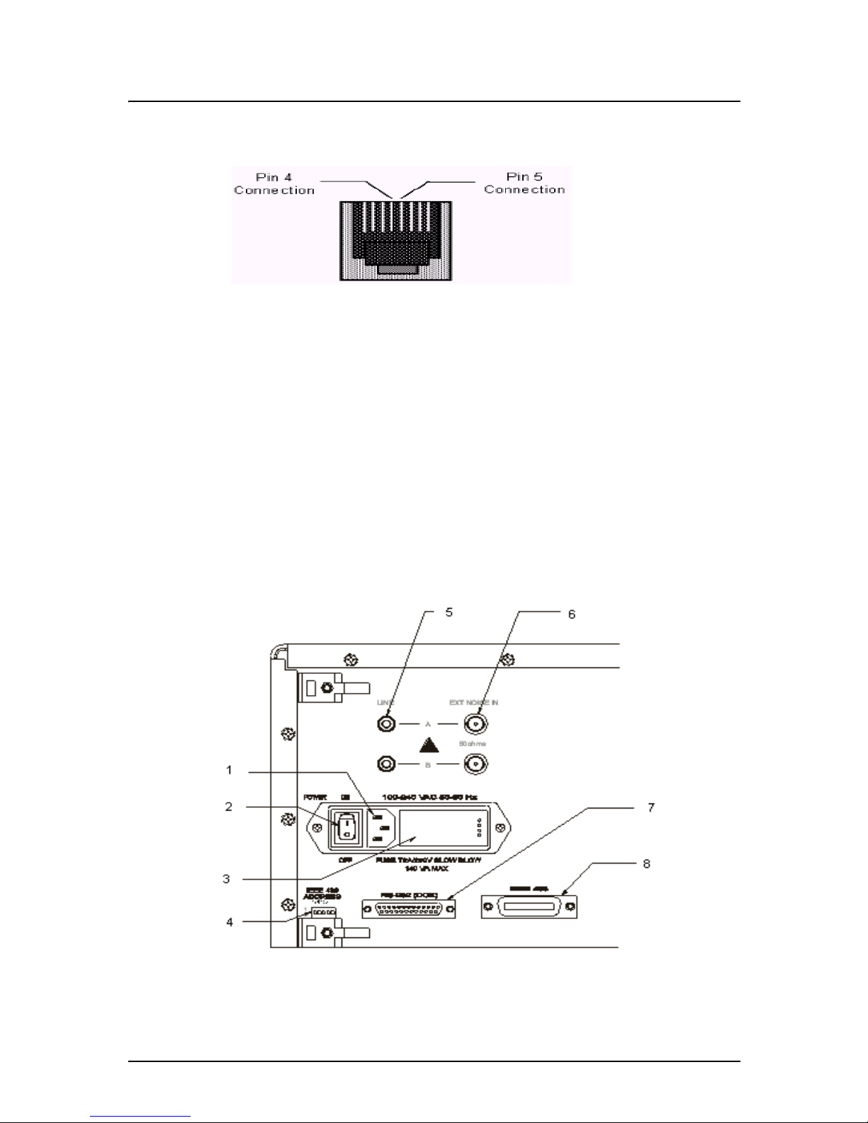
The pin out of the RJ-45 female connector is shown in Figure 2.2.
Wiring
Figure 2.2 RJ-45 Female Connector
In Figure 2.2 "RJ-45 Female Connector", Pins 4 (Tip) and 5 (Ring) of the RJ-45 connectors, the center 2
pins, carry the signal.
Note: RJ-11 male connectors can also mate to RJ-45 female receptacles.
These connections are balanced.
WARNING: The maximum input to the DLS 400E3 must not exceed -30 dBm between 50 Hz and 1
kHz. Exceeding these limits could damage the unit.
2.5 Back Panel Components and Connections
The connections on the rear panel are used for remote control (computer with DLS 400E3 Software), external noise injection and power. Figure 2.3 displays the key components of the rear panel.
Figure 2.3 DLS 400E3 Back Panel
Page 15

DLS 400E3 Operating Manual
Spirent Communications - Page 2-5
7104000537 03/04 -2
DLS 400E3 Back Panel Components
1) Power Input: for connecting to an AC power source
2) Power Switch: for turning power to the unit on or off
3) Fuse box: for fuse replacement when required
4) IEEE 488 Address DIP Switch: used to set a unique address for the unit
5) Side A Line Bantam Jack: used as an input/output connector
6) Side A External Noise IN BNC Connector: used to insert noise from an external source
7) RS–232 (DCE) Serial Connector: for connection to a computer for remote control
8) IEEE 488 Connector: for connection to a computer for remote control
2.5.5 Connecting to Power
Each of the two DLS 400E3 chassis are built with a 2-fuse configuration. Please refer to Chapter 12
"SAFETY" for more details.
Connect the power input which can be found at the back of each of the two DLS 400E3 chassis to an AC
line, voltage between 100 and 240 V
RMS
+/-10% and a frequency of 50 to 60 Hz. The DLS 400E3 can work
with any voltage and frequency in this range, switch settings are not required.
The DLS 400E3 always powers-up in an "idle" state. When powered off, the DLS 400E3 remains latched to
the previously selected loop settings, allowing the unit to be used when power is turned off.
Note: If the unit is powered off, internal noise generators will not output.
2.5.6 Injecting Noise in the System
You can inject externally-generated impairments using the CF or RJ45 connectors on the front of the
DLS 400E3. An external noise impairment generator can be purchased which can inject noise differentially
onto the wireline with a 4 KOhm Thevenin output impedance.
The DLS 400E3 also has (2) 50 Ohm BNC external noise inputs located on the rear panel. These inputs are
labelled as side A and B and can be used to inject noise when a DLS 5A01H noise card(s) are installed in the
noise card slots within the wireline chassis, this allows differential noise injection from external noise injection products.
The DLS 5200E3 Noise Generation System can generate both user-defined and pre-packaged noise shapes
from DC to 12 MHz. It provides convenient noise injection circuitry. For more information on the
DLS 5200E3 product, see the DLS 5200E3Operating Manual.
2.5.7 Connecting to a Windows Computer (for Remote Control)
You configure the DLS 400E3 wireline simulator remotely via a computer connected to either an IEEE 488
or an RS-232 interface on the rear panel of the simulator. There are two options available to control the
DLS 400E3, one being Spirent Communications’s DLS 400E3 Software, or the second being custom software / scripting using commands sets.
The DLS 400E3 Software allows you to select simulated or external jack termination for bridged taps, as
well as the type of calibration loop simulated. If you are developing custom control software, refer to Chapter 4 "COMMON COMMAND SET FOR REMOTE CONTROL"and Chapter 6 "DEVICE SPECIFIC
COMMANDS FOR REMOTE CONTROL" which discuss the accepted commands to configure the unit.
2.5.7.1 Connecting the Computer via the IEEE 488 Port (GPIB)
The IEEE 488 portion of the control software supplied by Spirent Communications only works with a
National™ IEEE 488 interface card. If necessary, install the National™ IEEE 488 interface card in the com-
Page 16
DLS 400E3 Operating Manual
Page 2-6 - Spirent Communications
7104000537 03/04 -2
puter. Please refer to the “NATIONAL INSTRUMENTS GPIB CARD AND SOFTWARE INSTALLATION” for information on how to install the NI card.
Connect one end of an IEEE 488 cable to the IEEE 488 connector located on the back panel of the
DLS 400E3. Connect the other end of the IEEE 488 cable to the IEEE 488 interface card in the computer.
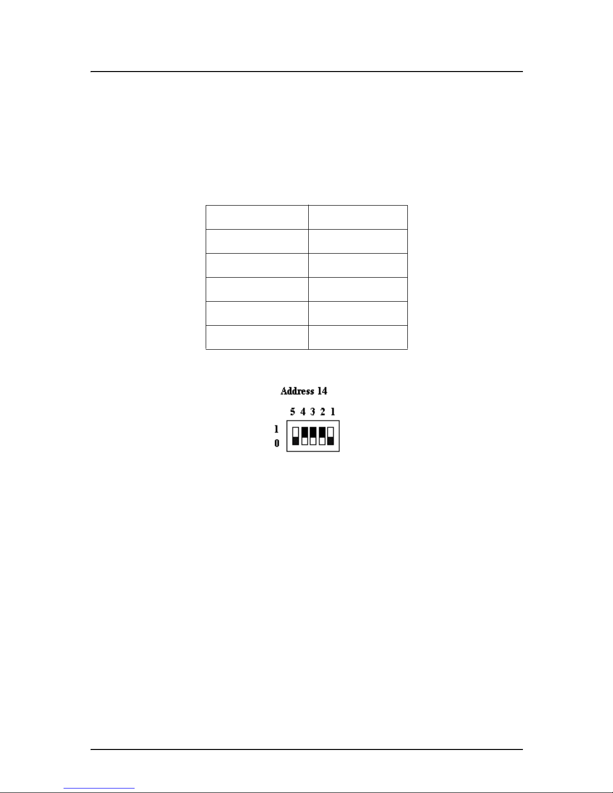
No two units on the same IEEE bus can have the same IEEE 488 address. In association with the system, the
DLS 400E3 can use any valid IEEE 488 address (from 0 to 30). You can change the address by using the
DIP switch on the back of the unit. The weighting is as follows:
The following figure shows the default switch setting which is set to address 14 (i.e. 0+8+4+2+0=14):
2.5.7.2 Connecting the Computer via the Serial Port (RS-232)
Connect one end of an RS-232 serial cable to the RS-232 connector located on the back panel of the
DLS 400E3 chassis and the other end to a serial COM port connector on the computer. The DLS 400E3
Software can be set to connect to serial port COM1 to COM9. Make sure there is no conflict with other
serial devices.
Table 2-1:Dip Switch Weightings
Dip Switch Weighting
AD5 16
AD4 8
AD3 4
AD2 2
AD1 1
Page 17

DLS 400E3 Operating Manual
Spirent Communications - Page 3-1
7104000537 03/04 -2
3. DLS 400E3 CONTROL SOFTWARE
3.1 About the Software
The DLS 400E3 has its own control software. This chapter details the DLS 400E3 Software options for controlling these simulators.
Please ensure that your simulator unit has the correct version of firmware required in order to operate with
the version of DLS 400E3 Software installed on your computer. If the necessary firmware is not detected
when the software queries the unit, then the DLS 400E3 Software informs you of an error. In the event of an
error, please contact Spirent Communications Customer Service for possible upgrade paths for the firmware.
The list of compatible firmware is contained in the DLS 400E3 Software release notes.
If you connect the computer to the simulator via the IEEE 488 (GPIB) port, ensure you install the National
Instruments GPIB - PC II/IIA or PCMCIA card and its associated software in your computer. For more
information please refer to National Instruments device-specific documentation and on-line help.
3.1.1 Computer Hardware and Software Requirements
You require the following to configure and control a simulator through either the serial port or IEEE 488
interface:
• If using the DLS 400E3 Software (provided with the unit):
• a computer running a version of the Windows® based operating system.
•National Instruments GPIB-PCII/GPIB-PCMCIA, and
•IEEE 488 cable
OR
•Serial port, and
•RS-232 serial cable.
Spirent Communications provides the DLS 400E3 Software to the control of the DLS 400E3 units
either through an RS-232 or IEEE 488 interface. Please see the release notes of the DLS 400E3 Software for a list of the current versions of Windows supported.
Control of the simulator may also be done through writing custom software to send commands over the RS232 or IEEE 488 port. See Chapter 4 "COMMON COMMAND SET FOR REMOTE CONTROL" and
Chapter 6 "DEVICE SPECIFIC COMMANDS FOR REMOTE CONTROL" for details about accepted
commands.
3.2 Installing the Software
Insert the DLS 400E3 Software Installation CD in the computer CD drive. The Installation Wizard starts.
Simply follow the instructions on the Wizard’s series of dialog boxes.
A DLS 400E3 icon should appear in the start menu when you have finished the installation. However, if you
do not see the icon, you can find the program in c:\Program Files\Spirent Communications\DLS 400E3
\DLS400E3.exe.
Page 18
DLS 400E3 Operating Manual
Page 3-2 - Spirent Communications
7104000537 03/04 -2
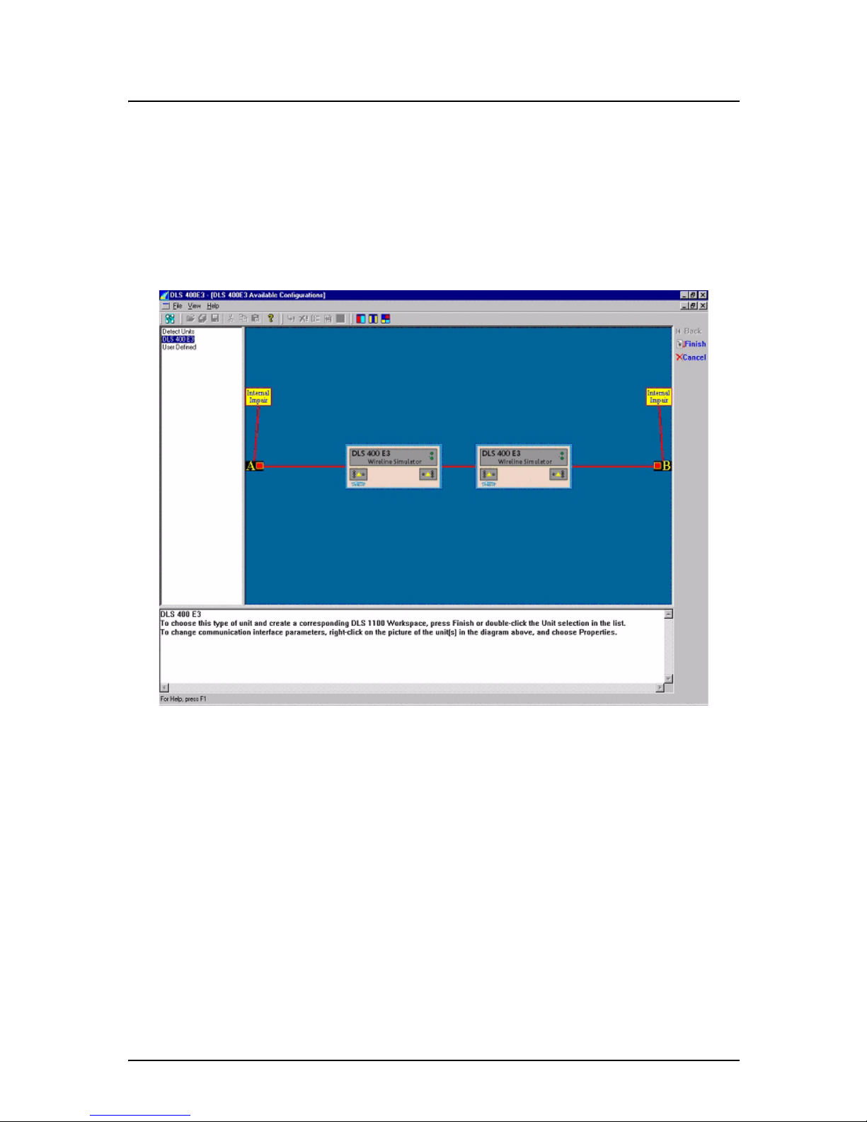
3.3 Accessing the Main Window
The left-hand side of main window displays a supported equipment menu listing all available models of simulators you can configure. When you highlight any item in the menu a diagram of the selected system
appears on the right-hand side of the main window workspace.
To access the main window:
1) From the Start menu, select DLS 400E3 Software or double-click the icon on your desktop. The
DLS 400E3 - (DLS 400E3 Available Configurations) window appears.
Figure 3.1 DLS 400E3 Software - Main Window
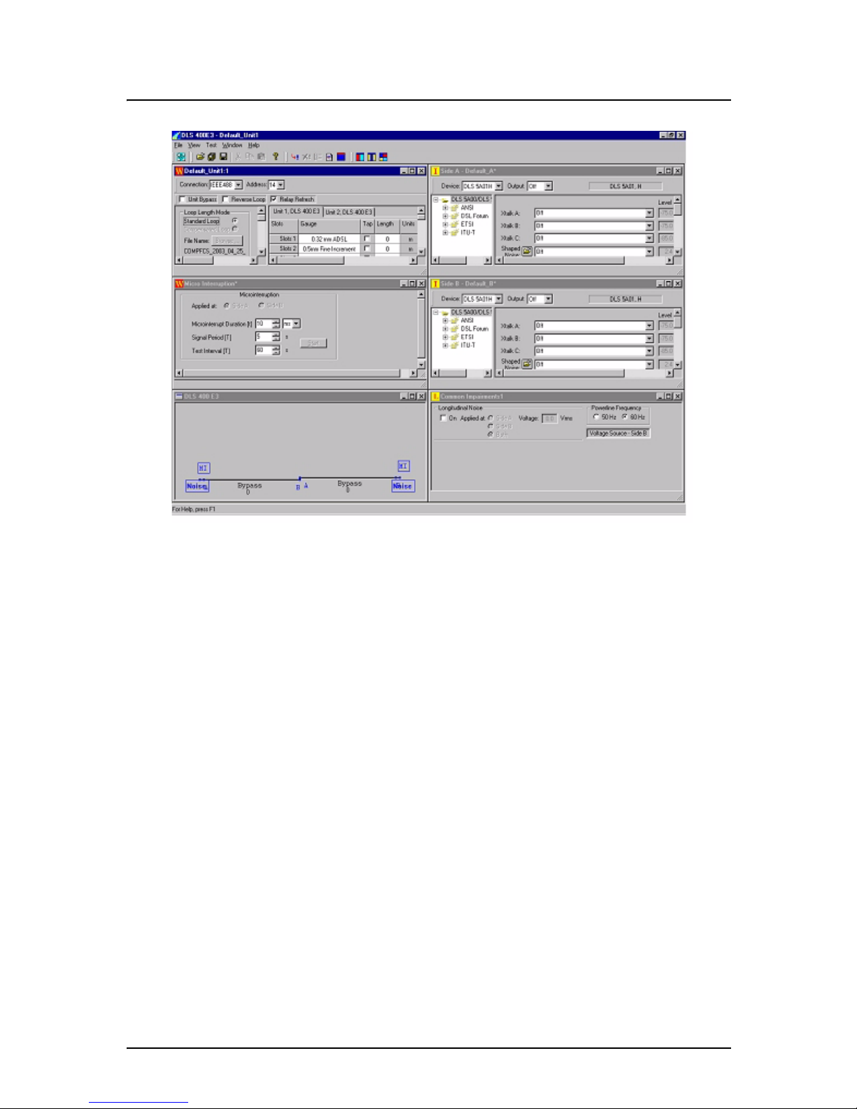
3.4 Accessing the Control Window (s)
The DLS 400E3 control window (s) contains the following in the workspace area as shown in Figure 3.2:
• Loop Display window that displays which test loop (s) is currently configured for the DLS 400E3.
• Unit Configuration window that displays the Unit 1 and 2 addresses and settings for the selected test
loop.
• Micro-interrupt window that allows you to set the micro-interruption feature.
• Optionally, Side A and Side B windows that allow you to set internal noise injector card configurations.
Page 19
DLS 400E3 Operating Manual
Spirent Communications - Page 3-3
7104000537 03/04 -2
Figure 3.2 DLS 400E3 Control Window (with Impairment Cards)
To access the control window for the DLS 400E3 simulator chassis 1 controls:
1) In the supported equipment menu, double-click Detect Units to have the program automatically
detect supported products connected via RS-232 or the IEEE 488 communication buses (optional
interface). The program automatically displays the connected units in the display area.
OR
2) Click User Defined, then manually select the desired wireline simulator in the supported equip-
ment menu. If you select a model of simulator not connected, the application will not execute.
3) Click Finish, on the upper right hand of the main window workspace. The DLS 400E3 -
Default_Unit 1 window appears with the Unit 1 Tab active (DLS 400E3 unit 1 chassis).
Page 20
DLS 400E3 Operating Manual
Page 3-4 - Spirent Communications
7104000537 03/04 -2
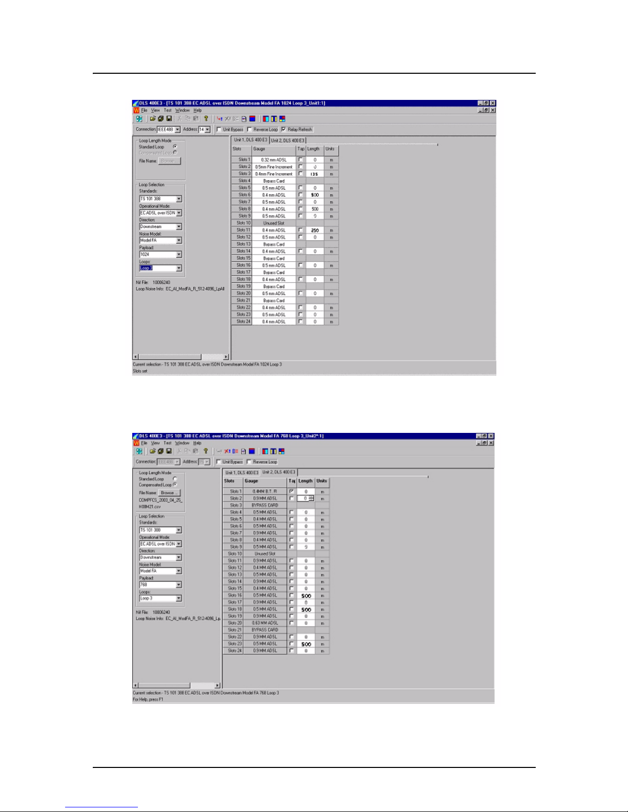
Figure 3.3 DLS 400E3 Unit 1 Control Window
To access the DLS 400E3 chassis 2 controls, click the Unit 2 Tab.
Figure 3.4 DLS 400E3 Unit 2 Control Window
Page 21

DLS 400E3 Operating Manual
Spirent Communications - Page 3-5
7104000537 03/04 -2
3.5 Configuring the DLS 400E3 Simulator
The DLS 400E3 simulates all loops required by ETSI TS 101 388, ETSI ETR 328 and DSL Forum TR 048
(0.4mm gauge type).
3.5.1 Identifying Simulator Connection
The software allows control of DLS 400E3 units via the IEEE 488 interface. In the DLS 400E3 Default_Unit 1 window or the DLS 400E3 - Default_Unit 2 window, the following fields set the correct
address for the unit chassis you wish to configure or control. When you selected Detect Units in the main
window and double-clicked the specific model of simulator, the address of the simulator is detected and displayed in the following fields. However, if required, you can modify the fields as follows:
Connection
Click the down-arrow and select the appropriate connection type between the desired chassis and the
computer from the drop down list. Your choice affects the Address/ComPort field. Your choices are:
The IEEE 488, Serial or Offline mode.
Note: If you select Offline, the Address field becomes unavailable.
Address
If you selected IEEE 488 in the Connection field, click the down-arrow and select the appropriate IEEE
488 (GPIB port) address of the simulator you wish to configure from the drop down list. Your choices
are: 1- 30. The default IEEE 488 address is 14. Factory address settings for unit 1 and unit 2 are 14 and
15 respectively.
OR
ComPort
If you selected Serial in the Connection field, click the down-arrow and select the appropriate serial port
(RS-232 port) address of the simulator you wish to configure from the drop down list. Your choices are:
1- 9. The default RS-232 address is 2.
3.5.2 Bypassing or Reversing Loops
Unit Bypass
Check this check box to bypass the units and connect both ends of the test circuit together (the DSLAM
and CPE modem). Clear this check box to consider the units’ simulated line segments in the test system.
Reverse Loop
Check this check box to reverse the connections to side A and B within the units. Clear this check box to
revert the terminals A and B connections to normal position.
Note: When a loop is reversed, the main control screen shows a reversed diagram of the loop and any
bridge taps but the side A and B remain at the same position on the control window.
3.5.3 Setting the Relay Refresh Feature
Certain types of communications equipment may not apply DC current to the DLS 400E3 simulator. In such
circumstances, and over an extended period of time, the simulator relays may develop a small amount of
resistance causing a change in the simulated wireline characteristics. The build up of oxidization on the relay
Page 22

DLS 400E3 Operating Manual
Page 3-6 - Spirent Communications
7104000537 03/04 -2
contacts causes this resistance, which is a normal characteristic of relays that are operated in the absence of
DC signals.
With the Relay Refresh (RR) feature you can inject whetting current on the simulated loop to prevent the
undesirable resistance resulting from contact degradation on the relays. Annual calibration is still required
for all DLS 400E3 units to ensure that they remain within specification.
This feature operates in the following steps:
1) With the simulator set to a loop, you select a new loop or change the loop configuration. The simu-
lator goes open-circuit (terminal A and B are disconnected from the simulated loop).
2) Set the relays and length for the new loop.
3) The simulator sends a DC current through the new loop for 1 second. Note that external equipment
under test is not affected.
4) The new loop is reconnected to terminals A and B, and you can send signals through the simulator.
In addition, the Relay Refresh feature has the following implications for the operation of the units:
• It keeps the internal relays working more reliably for the duration of their electrical life.
• It provides repeatability of results between successive loop settings. The feature adds one extra sec-
ond of delay from when the new loop is configured to when it is set.
• You may need to incorporate this additional second of delay in the scripting environment used to
control the DLS 400E3.
• The DLS 400E3 units open the simulated circuit between loops. This may lead to a slightly differ-
ent "train" time for the modems.
Relay Refresh
Check this check box to enable the relay refresh and inject whetting current on the simulated loop. Clear
this check box to disable the relay refresh feature.
3.5.4 Compensating Line Segment Lengths
The basic concept of wireline simulator compensation is to minimize the variation between different units,
and therefore promote uniform modem performance test results.
In the DLS 400E3, this compensation is done by slightly adjusting the length of a given loop such that the
new length exhibits an attenuation frequency response closer to the theoretical ideal.
Automated Compensation
To compliment the DLS 400E3 simulators, Spirent provides the DLS 1310E3 Compensation Software as an
option that allows you to verify actual 400E3 simulator accuracy. The program controls an Agilent 4395A
network/spectrum analyzer and a DLS 400E3 simulator. When you install this program, it connects to all
products over GPIB. The program then controls and generates signals using the network analyzer for every
test loop.
Based on the results gathered, the DLS 1310E3 Compensation Software then provides adjusted values for
the loop that best match theory.
Each DLS 400E3 release includes two compensation files, a loopset file and an E3 standard setting file to
help you. The "E3 standard" file associates each test loop to an ID number, while the other files relate specific unit 1 and unit 2 slot settings to this ID number. When you select compensation feature within the DLS
400E3 Software, the application uses these compensation files to automatically adjust the slot settings to the
compensated values.
With the DLS 400E3 you are supplied with the following four ’csv’ files:
1) Stand ards File - associates an ID to every possible loop configuration, supported by the DLS 400E3
Page 23

DLS 400E3 Operating Manual
Spirent Communications - Page 3-7
7104000537 03/04 -2
2a) DLS 400E3 Standard Slot Settings File - associates each ID to generic simulator compensation settings
for each slot
2b) Factory Compensated File - associates each ID to factory compensation settings for each slot, for your
particular unit
2c) 1310 Compensated File - associates each ID to DLS 1310-generated simulator compensation settings
for each slot, for your particular unit in your lab environment
Note: To use the compensation feature with remote control, see Section 5.4 "Remote Control for Compen-
sated Loops".
To use the automated compensation feature:
1) In the Loop Length Mode area, select the Compensated Loop option button. The Browse button
becomes available.
2) Click the Browse button to open a standard Windows Open dialog box where you navigate to the
desired compensated slot settings file. This file is now used to compensate the standard slot settings
for the selected test loop.
3.5.5 Selecting the Test Loop
Note: In the Loop Selection area, the field names change based on the value you select in the Standard
field:
For example, to select a test loop for TS 101 388:
In the Loop Selection area, select the appropriate parameters from the following fields in order from top to
bottom:
Standards
Click the down-arrow and select the desired standard from the drop-down list. The available options
are: TR-048 (0.4mm gauge type), TS 101 388, ETR 328 and WT-085.
Operational Mode
Click the down-arrow and select the desired operational mode from the drop-down list.
Direction
Click the down-arrow and select the desired upstream or downstream direction from the drop-down list.
Noise Model
Click the down-arrow and select the desired noise model from the drop-down list.
Payload
Click the down-arrow and select the desired payload from the drop-down list.
Loops
Click the down-arrow and select the desired loop from the drop-down list.
Note: Each choice you make in the preceding fields affect the choices available in the following fields.
Page 24

DLS 400E3 Operating Manual
Page 3-8 - Spirent Communications
7104000537 03/04 -2
Nif File
After you make selection in all the fields in the Loop Selection area, this field displays the required
noise information file number which may need to be loaded to the 5A01H/5103 noise card.
Loop Info
After you make selection in all the fields in the Loop Selection area, this field displays the loop noise
information file number.
If you select a Loop Length Mode as Standard Loop, both unit 1 and unit 2 tabs now show the uncompensated slot settings for each of the 24 slots.
If you select a Loop Length Mode as Compensated Loop, both unit 1 and unit 2 tabs now show the compensated slot settings for each of the 24 slots.
3.5.6 Configuring Line Segments
These fields typically display settings based on the test loop selected. Typically, you only need to modify
settings to allow for compensation.
Bridged taps are always adjusted in unit 2 slot 1.
Slots
Displays the number of each of the 24 wireline card slots for each unit.
Gauge
Displays the gauge of wireline for each of the 24 wireline card slots for each unit.
Tap
Check this check box to set the card, in the associated slot, to represent a bridged tap. Clear this check
box to switch this segment to the default of inline.
Note: The Bridged Tap card in slot 1 of the Unit 2, must always be set as a bridged tap slot and cannot
be used as an inline slot.
Length
Displays the length (in meters) of the line segment represented by the card in this slot for the selected
test loop. Optionally, to change this length, type the new value directly in the field. To adjust this length
for compensated values see Section 3.5.4 "Compensating Line Segment Lengths".
Units
Displays the unit of measurement in meters. The DLS 400E3 comes factory-shipped metric wireline
cards.
3.5.7 Micro Interruption Feature Overview
The micro interruption (MI) feature allows the DLS 400E3 to accurately simulate the ANSI, ETSI, and
ITU T standards specified micro-interruption testing.
A micro interruption is a temporary interruption due to external mechanical action on the copper wires constituting the transmission segment, for example, at a cable splice. The effect of a micro-interruption on the
Page 25

DLS 400E3 Operating Manual
Spirent Communications - Page 3-9
7104000537 03/04 -2
transmission system can be a failure of the digital transmission link, together with a failure of the span
power feeding (if provided) for the duration of the micro-interruption.
The operating objective is that in the presence of a micro-interruption of specified maximum length, the system (e.g. DSLAM and corresponding modem) does not reset, the system automatically reactivate or retrain
with a complete start-up procedure if a reset occurs due to an interruption. These parameters are defined in
the ADSL, HDSL2 and SHDSL standards like the ITU-T G.shdsl / G.991.2.
The following graph from the ITU-T G.shdsl standard illustrates the specified micro interruption.
Figure 3.5 Micro Interruption Test Circuit
The standard specifies two configurations based on the powering of the TU-R. The default values for the
micro interruption variables are as follows:
• Micro interruption duration (t)
• 10 ms when TU-R is powered locally
• 1 ms when TU-R is span powered (remotely powered)
• Signal period (T): 5 s
• Test interval: 60 s (total test duration)
In addition to the standard specified values, all the micro interruption variables are custom configurable to
be applied to any of the loops the DLS 400E3 simulates.
3.5.7.1 Setting the Micro Interruption Feature
The micro interruption feature is controlled in the Micro Interruption control window by setting values in
the following fields.
TU-C
TU-R
Test Loop
Impulse
Generator
S
t
T
Page 26

DLS 400E3 Operating Manual
Page 3-10 - Spirent Communications
7104000537 03/04 -2
Figure 3.6 Micro-Interruption Control Window
Applied at
Select one of the three option buttons to apply a micro interruption at Side A, Side B, or both sides.
Micro-Interruption Duration (t)
Enter the micro interrupt duration directly in the field or use the up and down arrows on the spin box.
The range is: 1 ms to 15 seconds.
Then click the down arrow in the field to the right to select the units of measure from the list. Your
choices are: milliseconds or seconds.
Signal Period (T)
Enter the signal period duration (in seconds) directly in the field or use the up and down arrows on the
spin box. The range is: 3 to 360 seconds.
Test Interval (TI)
Enter the test interval duration (in seconds) directly in the field or use the up and down arrows on the
spin box. The range is: 3 to 360 seconds
Start/Stop
Click the button to begin the MI test. A dialog box appears showing the progress of the MI test. The
Start button changes to a Stop button. To stop the test, click on the Stop button. The button changes to
a Start button.
Note: While the micro-interruption test is in progress, only the command to stop the micro-interruption
test is accepted by the DLS 400 unit. All other commands are ignored until the test is completed.
3.5.8 Configuring Internal Noise Impairment Cards
For information about configuring internal impairment cards see the DLS 5A01H/5103/5104 Operating
Manual.
Page 27

DLS 400E3 Operating Manual
Spirent Communications - Page 4-1
7104000537 03/04 -2
4. COMMON COMMAND SET FOR REMOTE CONTROL
4.1 Generic IEEE 488 & RS-232 Controls
The DLS 400E3 is controlled via IEEE 488 (also known as the GPIB or HPIB bus), or the RS-232 (serial)
interface, allowing the integration of the simulator into a larger test system.
The system remote control is designed with several standards in mind:
• The GPIB physical interface follows IEEE 488.1. The functions implemented are outlined in the “IEEE
488 INTERFACE” Section.
• The Common Commands follow IEEE 488.2.
• The Device Dependent Commands (see Chapter 6 "DEVICE SPECIFIC COMMANDS FOR REMOTE
CONTROL") are based upon the Standard Commands for Programmable Interfaces (SCPI).
• The serial port physical interface follows the EIA RS-232 standard.
The IEEE 488 and the serial interfaces are always enabled and either can be used. The host system directs its
output to the last interface from which it received data. Both interfaces use the same command set and produce the same results.
Section 4.2 "IEEE 488 Interface" and Section 4.3 "RS-232 Serial Interface" describe features specific to one
particular interface, and the rest of this section describes the commands that are common to both interfaces.
4.2 IEEE 488 Interface
This Section contains information specific to the IEEE 488 interface. Section 4.3 "RS-232 Serial Interface"
contains the information specific to the RS-232 interface.
4.2.1 IEEE 488.1 Interface functions supported
The IEEE 488.1 Interface functions supported by the DLS 400E3 are as follows:
SH1 Source handshake - full capability
AH1 Acceptor handshake - full capability
T5 Basic talker - serial poll, untalk on MLA
L3 Basic listener - unlisten on MTA
SR1 Service request - full
DC1 Device clear - full
C4 Respond to SRQ
E1 Open Collector drivers
RL1 Remote Local - full
These represent the minimum required to implement the IEEE 488.2 standard.
4.2.2 The Service Request (SRQ) Line
The SRQ line is raised when the simulator is requesting service. Here are some examples of services that
could raise SRQ:
•a message is available in the output buffer
Page 28

DLS 400E3 Operating Manual
Page 4-2 - Spirent Communications
7104000537 03/04 -2
•an error occurred
•all pending operations are completed
•the power was just turned on
In order to use the SRQ line, all relevant enable bits must be set.
For example:
•the SRQ line can be raised automatically when there is a message available by enabling the MAV bit
(bit 4) in the Status Byte Register with the command *SRE 16.
•the SRQ line can be raised automatically when there is an error by enabling the ESB bit (bit 5) in the
Status Byte Register with *SRE 32 and by enabling the error bits in the Standard Event Status Register with *ESE 60 (bit 2, 3, 4 and 5).
NOTE: The Factory default is to clear all registers on power up. See *PSC, *ESE and *SRE commands for more details.
It is recommended that the simulator be set to raise the SRQ line when there is a message available and when
there is an error.
4.2.3 Message Terminators
Messages to the system must be terminated with either a Line Feed character (ASCII <LF>, decimal 10, hex
0A), an IEEE 488.1 EOI signal, or both. Messages from the system are always terminated with a Line Feed
character and the IEEE 488.1 EOI signal.
Note that some software languages may automatically append a carriage return and a line feed at the end of
messages. The carriage return character is not a valid terminator, and invalidates the last command. To avoid
this problem, in BASIC, you can append a semi-colon after a string (after the quotes) when printing to the
IEEE 488 port. Another solution is to append a semi-colon at the end of the command itself (inside the
quotes), so that the carriage return can be interpreted as a second command, and be simply discarded by the
system.
For example:
PRINT #1, ":sourceB:output on"+CHR$(10);Preferred solution
or
PRINT #1, ":sourceB:output on;" Other solution
4.2.4 Example using the IEEE 488 Interface
To enable the output stage, do the following:
• transmit ":SOURCEB:OUTPUT ON".
• check that the REMOTE LED is green.
To send and receive messages with error checking follow these steps:
• set all relevant enable bits (only done once).
• send the message.
• wait for SRQ.
• read the Status Byte.
• if MAV (bit 4) is set then read the response.
• if ESB (bit 5) is set then read the Standard Event Status Register and take all the relevant
actions.
Page 29

DLS 400E3 Operating Manual
Spirent Communications - Page 4-3
7104000537 03/04 -2
For example, to get the identification message with the IEEE 488 interface, do the following:
4.3 RS-232 Serial Interface
This section contains information specific to the RS-232 interface. Section 4.2 "IEEE 488 Interface" contains the information specific to the IEEE 488 interface.
The system uses a female DB-25 connector, and is configured as a DCE device. It can be connected directly
to your PC serial port.
Do NOT use a null modem with a computer that has a standard COM port configured as a DTE.
To use the RS-232 interface, simply connect your computer to the host system and set the computer to 9600
bps baud rate, no parity, 8 data bits per character, 1 stop bit and RTS/CTS hardware flow control.
The RS-232 standard is equivalent to the European V.24/V.28 standards. In this manual we use the term RS232 to refer to both of these two standards. Generally, the computer literature uses the words "serial",
Table 2-2:IEEE 488 example
Action
Comment
transmit “*SRE 48”
enable MAV and ESB (needed only once)
transmit “*ESE 60”
enable all the error bits (needed only once)
transmit “*IDN?”
query the identification message
wait for SRQ to be raised
read the status byte
use the IEEE 488.1 serial poll command, not *STB?
if MAV (bit 4) is set, read the
response
if ESB (bit 5) is set, do the following
check if an error was detected
transmit “*ESR?”
query the Event Status Register
wait for SRQ to be raised
if MAV (bit 4) is set read the
response and take all relevant
action according to the error
type received
If desired, all the enable registers can be restored on power
up with the *PSC command
Page 30

DLS 400E3 Operating Manual
Page 4-4 - Spirent Communications
7104000537 03/04 -2
"COM1" and "COM2" to refer to the RS-232 interface. Note that the host system cannot use the parallel
(printer) port of a computer.
The system stops transmitting data when the RTS line is low, and restarts when the RTS line is high. The
host system lowers the CTS and the DSR lines when it cannot accept data, and raises them when it can. Note
that the RTS line is not the usual "Request To Send" as defined by the RS-232 standard. If desired, you can
leave the RTS line set, and use only the CTS line.
Most serial port communication programs can be used to control the host system. To use HyperTerminal,
click on "Start" > "Programs" > "Accessories" > "HyperTerminal" > "hypertrm.exe". When the program
starts, enter a name (for example; "DLS 400"); select the port, (for example; "Direct to COM1"). Enter the
port settings: 9600, 8, none, 1 and hardware. Select "File" > "Properties" > "Settings" > "ASCII Setup", enable "Send line ends with line feeds" and "Echo typed characters locally", and finally press "OK" twice. You
should now be able to send and receive commands to and from the system.
4.3.1 Message Terminators
Messages sent to the system through the serial interface MUST be terminated with the line feed character
(decimal 10, hex 0A, LF). To ensure that no characters are left in the receive buffer of the system from a previous incomplete command, you can send the line feed character by itself before sending new commands.
Messages from the system are always terminated with a Line Feed character.
Note that some languages, such as BASIC, may automatically append a carriage return and a line feed at the
end of messages. The carriage return character is not a valid terminator, and invalidates the last command.
To avoid this problem, you can append a semi-colon after a string (after the quotes) when printing to the
IEEE 488 port. Another solution is to append a semi-colon at the end of the command itself (inside the
quotes), so that the carriage return can be interpreted as a second command, and be simply discarded by the
system.
For example:
PRINT #1, ":sourceB:output on"+CHR$(10);Preferred solution
or
PRINT #1, ":sourceB:output on;" Other solution
4.3.2 Example using the RS-232 Interface
To enable the output stage, do the following:
• transmit ":sourceB:OUTPUT ON"
• check that the REMOTE LED is green
•
To send and receive messages with error checking follow these steps:
• set all relevant enable bits (only done once)
• send the message
• read the answer until you receive LF (decimal 10, hex 0A)
• check if an error occurred with the command *ESR?
For example, to get the identification message with the RS-232 interface, do the following:
Page 31

DLS 400E3 Operating Manual
Spirent Communications - Page 4-5
7104000537 03/04 -2
4.4 Data Formats
This section applies to both the IEEE 488 and RS-232 interfaces.
The host systemhost system adheres to the IEEE 488.2 principle of Forgiving, Listening and Precise Talking.
The data formats supported by the host system are:
Talking: a) <NR1> Numeric Response Data - Integer
b) Arbitrary ASCII Response Data
<NR1> is an implicit point representation of an integer (i.e. fixed format).
Arbitrary ASCII Response Data is a generic character string without any delimiting characters. It is usually
used to send data in response to a query, such as with the *IDN? command.
Listening: <NRf> Decimal Numeric Program Data
<NRf> is the Flexible Numeric Representation defined in the IEEE.2 standard which can represent just
about any number.
The host system can accept data in the <NRf> format, which means that numbers can be made of a combination of digits, signs, decimal points, exponents, multipliers, units and spaces. For example, any of the following is a valid representation for -85.0 dBm: -85dbm, -85.0 dbm, -85, -85.0, -8.5e2. If a unit (i.e. dB, pps,
mv, etc) is appended to a number, that unit must be valid and not abbreviated. Note that the period separates
the decimal part of a number.
4.5 Command Syntax
The host system adheres to the IEEE 488.2 format for command syntax. As with the Data Format, the principle is Forgiving Listening and Precise Talking.
Commands may take one of two forms, either a Common Command or a Device Dependent Command. The
format of each is detailed in their respective sections Chapter 4 "COMMON COMMAND SET FOR
REMOTE CONTROL", and Chapter 6 "DEVICE SPECIFIC COMMANDS FOR REMOTE CONTROL").
Each type may be preceded by one or more spaces, and each must have one or more spaces between its mnemonic and the data associated with it.
Common commands are preceded by the character "*". Device Dependent commands are preceded by a
colon, with a colon separating each level of the command. Commands may be either in upper or lower case.
Multiple commands may be concatenated by separating each command by semi-colons.
The following are some examples:
Table 2-3:RS-232 Example
Action
Comment
transmit "*ESE 60
enable all the error bits (needed only once)
transmit "*IDN?
query the identification message
read the answer
the messages are always terminated with LF
transmit "*ESR?
check if an error occurred
read the answer
Page 32

DLS 400E3 Operating Manual
Page 4-6 - Spirent Communications
7104000537 03/04 -2
*RST.,
*RST;*WAI;:sourceA:output off
*ESE 45; *SRE 16
IEEE 488 messages to the host system may be terminated with either a Line Feed character (ASCII <LF>,
decimal 10, hex 0A), an IEEE 488 EOI signal or both. RS-232 messages must be terminated with a line feed
character. Messages from the host system are always terminated with a Line Feed character, and also with
the EOI signal if using the IEEE 488 interface.
As defined in the SCPI specifications, a Device Dependent Command may be sent in its short or long form,
in upper or lower case. The following commands therefore are identical in operation:
:sourceA:IMPULSE:RATE 100 PPS
:sourceA:IMPULSE:RATE 100
:sourceA:IMPULSE:RAT 100
:sourceA:IMP:RAT 100
:sourceA:impulse:rate 100
:sourceA:Impulse:Rate 100 pps
Queries of the system follow the same format as the commands, except that the data normally associated
with a command is replaced by a question mark "?". Following receipt of such a command, the simulator
places the appropriate response in the output queue, where the controller can read it.
Examples are:
*IDN?
*ESE?;*SRE?
:sourceA:IMPULSE:RATE?
When a command does not begin with a colon, the simulator assumes that the command is at the same level
as the previous command. For example, to set the impulse, it is NOT necessary to specify
":sourceB:IMPULSE" for each parameter but rather the following command may be used:
:sourceA:IMPULSE:TYPE BIPOLAR;RATE 100;WIDTH 50
4.6 Self-Test
The DLS 400E3 has 2 LEDS which indicate the power status and the remote status of the units.
The POWER LED turns green when the power is turned on or after a reset. The POWER LED turns yellow
if it detects an internal error.
The REMOTE LED turns off after a power-up and a reset, when the simulator receives the first remote command message, the REMOTE LED turns green. If the simulator detects an error in the message the
REMOTE LED turns red and stay red until the error flags are cleared.
When power is first switched on, the simulator does a series of self-tests. If any of the self-tests fail, the simulator flashes the POWER LED red, in which case Spirent Communications Customer Service should be
contacted. Contact information can be found in Chapter 8 "CUSTOMER SUPPORT".
The following is a short description of some of the self-tests the simulator performs:
1) A check to see if the checksum of the EPROM is valid.
2) A check to see if the non-volatile RAM is functional. The battery has an expected life of over 10
years, and, if necessary, it can be easily replaced.
Page 33

DLS 400E3 Operating Manual
Spirent Communications - Page 4-7
7104000537 03/04 -2
3) A check to see if the controller card is functional
Following the self-tests, the simulator re-establishes the loop that was in use before the unit was turned off or
reset. Any impairment modules in the system is set so that all impairments are OFF.
4.7 Common Command Set
As specified in the IEEE 488.2 standard, a number of common commands are required to set up and control
of the standard functions of remote-controlled devices. They can be used with both the IEEE 488 and the
RS–232 interfaces. These common commands are as follows:
*CLS Clear Status Command
Type: Status command
Function: Clears the Event Status Register (ESR). Clearing the Event Status Register also clears
ESB, the bit 5 of the Status Byte Register (STB). It has no effect on the output queue (bit 4
of the STB).
*ESE <NRf> Event Status Enable
Type: Status command
Function: Sets the Event Status Enable Register (ESER) using an integer value from 0 to 255, repre-
senting a sum of the bits in the following bit map:
Bits 7 to 0 have values of 128, 64, 32, 16, 8, 4, 2 and 1, respectively. For example, if bits 3
and 5 are set then the integer value is 40 (8+32).
The ESER masks which bits are enabled in the Event Status Register (ESR).
On power-on, the register is cleared if the Power-on Status Clear bit is 1, or restored if the
bit is 0 (see *PSC for more details).
*ESE? Event Status Enable Query
Type: Status command
Function: An integer value between 0 and 255 representing the value of the Event Status Enable
Register (ESER) is placed in the output queue. The possible values are described in the
*ESE command section.
*ESR? Event Status Register Query
Type: Status command
Function: An integer value between 0 and 255 representing the value of the Event Status Register
(ESR) is placed in the output queue. Once the value is placed in the output queue, the register is cleared. The command turns the REMOTE LED green if the LED was red. The
possible values are described in the *ESE command section.
Page 34

DLS 400E3 Operating Manual
Page 4-8 - Spirent Communications
7104000537 03/04 -2
*IDN? Identification Query
Type: System command
Function: Returns the ID of the unit. Upon receiving this command the host system puts the follow-
ing string into the output queue:
SPIRENT COMM INC,host system,<SN>,<Ver>
where:<SN> is the serial number of the unit
<Ver> is the revision level of the control firmware (always 2 digits)
*OPC Operation Complete
Type: Synchronization command
Function: Indicates to the controller when the current operation is complete. This command causes
the host system to set bit 0 in the Event Status Register (ESR) when all pending operations
are completed. The bit is read with the *ESR? command, which also clear the bit. Communication can proceed as normal after this command, but be prepared to receive SRQ at
any time.
*OPC? Operation Complete Query
Type: Synchronization command
Function: Indicates when the current operation is complete. This causes the host system to put an
ASCII 1 (decimal 49, hex 31) in the output queue when the current operation is complete.
Communication can proceed as normal after this command, but be prepared to receive the
“1” at any time.
*PSC <NRf> Power-on Status Clear
Type: Status and event command
Function: Indicates if the unit should clear the Service Request Enable Register and the Standard
Event Status Register at power-on. If 1 (or higher) then all the enable registers are cleared
at power-on, if 0 then all the enable registers are restored from the non-volatile RAM at
power-on. The factory default is 1 (clear all the enable registers). Any change to the
“Power-on Status” is saved in non-volatile RAM, and is always restored on power up.
*PSC? Power-on Status Clear Query
Type: Status and event command
Function: Return the Power-on Status Clear value. If 1 then all the enable registers are cleared at
power-on, if 0 then all the enable registers are restored from the non-volatile RAM at
power-on. The factory default is 1 (clear all the enable registers).
*RST Reset
Type: Internal command
Function: IEEE 488.2 level 3 reset. This command initializes the host system with the bypass loop,
and cancel any pending *OPC operation. It does not affect the output buffer or other system settings of the unit. Note that this is NOT equivalent to the power-up reset and the
IEEE 488 “Device Clear”.
*SRE <NRf> Service Request Enable
Type: Status command
Page 35

DLS 400E3 Operating Manual
Spirent Communications - Page 4-9
7104000537 03/04 -2
Function: Sets the Service Request Enable Register (SRER). An integer value indicates which serv-
ice is enabled, with the following bit map:
Bits 7 to 0 have values of 128, 64, 32, 16, 8, 4, 2 and 1, respectively. For example, if bits 4
and 5 are set then the integer value is 48 (16+32).
Note that if both MAV and ESB are disabled, then the bits MSS and RQS and the line
SRQ are never going to be raised.
On power-on, this register is cleared if the Power-on Status Clear bit is 1, or restored if the
bit is 0 (see *PSC for more details).
*SRE? Service Request Enable Query
Type: Status command
Function: An integer value representing the value of the Service Request Enable Register is placed
in the output queue. The possible values are listed in the *SRE command section.
*STB? Status Byte Query
Type: Status command
Function: The value of the Status Byte Register is put into the output queue. Contrary to the
“*ESR?” command, this register is not cleared by reading it. The register is zero only
when all its related structures are cleared, namely the Event Status Register (ESR) and the
output queue.
Bits 7 to 0 have values of 128, 64, 32, 16, 8, 4, 2 and 1, respectively. For example, if bits 4
and 5 are set then the integer value is 48 (16+32).
Note that bit 6 is MSS, which does not necessarily have the same value as RQS.
*TST? Self-Test Query
Type: Internal command
Page 36

DLS 400E3 Operating Manual
Page 4-10 - Spirent Communications
7104000537 03/04 -2
Function: Returns the results of the self-test done at power up. The number returned has the follow-
ing bit map:
Bits 7 to 0 have values of 128, 64, 32, 16, 8, 4, 2 and 1, respectively. For example, if bits 3
and 5 are set then the integer value is 40 (8+32).
*WAI Wait to continue
Type: Synchronization command
Function: Used to delay execution of commands. The host system ensures that all commands
received before “*WAI” are completed before processing any new commands. This means
that all further communication with the host system is frozen until all pending operations
are completed.
4.8 Status Reporting
There are two registers that record and report the system status, the Status Byte Register (STB), and the
Event Status Register (ESR).
For both registers there are three basic commands: one to read the register, one to set the enabling bits, and
one to read the enabling bits.
Where <NRf> is the new value of the register.
4.8.1 Status Byte Register (STB)
The bits of this register are mapped as follows:
bit 4: MAV (Message Available Bit)
Indicates that the Output Queue is not empty. If MAV goes high and is enabled then MSS
goes high.
Table 2-4:Register Commands
Status Byte Register Event Status Register
Read Register
*STB? *ESR?
Set Enabling Bits
*SRE <NRf> *ESE <NRf>
Read Enabling Bits
*SRE? *ESE?
Page 37

DLS 400E3 Operating Manual
Spirent Communications - Page 4-11
7104000537 03/04 -2
bit 5: ESB (Event Status Bit)
It indicates that at least one bit of the Event Status Register is non zero and enabled. If
ESB goes high and is enabled then MSS goes high.
bit 6: MSS/RQS (Master Summary Status/Request Service)
MSS is raised when either MAV or ESB are raised and enabled. When the status of MSS
changes, the whole Status Byte Register is copied into the Status Byte of the GPIB controller, where bit 6 is called RQS. When RQS goes high so does the SRQ line, and in
response to an IEEE 488.1 Serial Poll command, both are cleared.
RQS and SRQ are defined by the IEEE 488.1 standard and are hardware related. MSS
summarizes all the status bits of the DLS 400E3, as defined by the IEEE 488.2 standard.
bits 7, 3, 2, 1,and 0: these bits are not used by the host system.
4.8.1.1 Event Status Register (ESR)
The Event Status Register monitors events within the system and reports on those enabled. It records transitory events as well. The host system implements only the IEEE 488.2 Standard Event Status Register (ESR).
It is defined as:
bit 0 Operation Complete. This bit is set in response to the *OPC command when the current operation
is complete.
bit 1 Request Control. The host system does not have the ability to control the IEEE bus, and so this bit
is always 0.
bit 2 Query Error. There was an attempt to read an empty output queue or there was an output queue
overflow. (maximum output queue capacity is 75 bytes).
bit 3 Device Dependent Error. This error bit is set when the host system receive a command to set the
length of a fixed loop. Only variable loops can have their length changed.
bit 4 Execution Error. The data associated with a command was out of range.
bit 5 Command Error. Either a syntax error (order of command words) or a semantic error (spelling of
command words) has occurred. A GET (Group Execute Trigger) or *TRG command also sets this
bit.
bit 6 User Request. Indicates that you have activated a Device Defined control through the front panel.
Not used, so this bit is always 0.
bit 7 Power on. This bit is set when the host system is turn on. Sending *ESR? clears the bit and stays
clear until the power is turned on again.
The setting of the Event Status Register can be read with the Event Status Register query command
(*ESR?). This puts the value of the register in the output queue, AND clears the register.
4.8.2 Host System Synchronization
The program controlling the host system can use three different commands to synchronize with the DLS
400E3: *OPC, *OPC? and *WAI. Following are the main differences:
Page 38

DLS 400E3 Operating Manual
Page 4-12 - Spirent Communications
7104000537 03/04 -2
1. if “Operation Complete” and ESB are enabled
2. if MAV is enabled
The main difference between OPC and WAI is that WAI blocks any further communication with the
host system until all pending operations are completed.
The main difference between *OPC and *OPC? is that *OPC sets the “Operation Complete” bit, and *OPC?
returns an ASCII “1” when all pending operations are completed.
Make sure that all the required enable bits are set.
When using *OPC or *OPC?, the program controlling the host system can determine when the operation is
completed by waiting for SRQ, or by reading the status byte with the serial poll or with *STB? (if corresponding bits are enabled).
If the program uses the *OPC? command and then sends more queries, the program must be ready to receive
the “1” concatenated to other responses at any time. When using *WAI, the communication time out should
be set long enough to avoid losing data (the host system needs approximately 2 seconds to set a loop).
Table 2-5:Synchronization commands
Set
Operation
Complete
bit when
Done
Return “1”
when
operation
complete
Raise SRQ
when
operation
complete
Block comm.
with the
DLS 400E3
Required
Enable Bit(s)
*OPC Ye s N o
Ye s
1
No
Operation
Complete, ESB
*OPC? No Yes
Ye s
2
No MAV
*WAI No No No Yes none
Page 39

DLS 400E3 Operating Manual
Spirent Communications - Page 5-1
7104000537 03/04 -2
5. DLS 400E3 LOOP DESCRIPTIONS FOR REMOTE CONTROL
5.1 DLS 400E3 Loop Configurations
The DLS 400E3 can simulate all loops required by ETSI TS 101 388, ETSI ETR 328 and DSL Forum
TR 048 (0.4mm loops).
5.2 Reversing Loops
You can reverse all loops with remote software control. The effect of doing this is to reverse the connections
to side A and B within the DLS 400E3.
Note: When a loop is reversed, the main control screen shows a reversed diagram of the loop and any
bridged taps but the side (A and B) remain at the same position on the control window.
5.3 DLS 400E3 Fine Increment Wireline Card
The Fine Increment Wireline Card in conjunction with the DLS 1310E3 Compensation Software, allow tuning of the simulator to your lab environment. These are three types of Fine Increment Wireline Cards and
their slot locations: 0.4 mm (unit 1, slot 3), 0.5 mm (unit 1, slot 2) and 0.4 Bridged Tap (unit 2, slot 1).
5.4 Remote Control for Compensated Loops
With the DLS 400E3 you are supplied with the following four ’csv’ files:
1) Stand ards File - associates an ID to every possible loop configuration, supported by the DLS 400E3
2a) DLS 400E3 Standard Slot Settings File - associates each ID to generic simulator compensation settings
for each slot
2b) Factory Compensated File - associates each ID to factory compensation settings for each slot, for your
particular unit
2c) 1310 Compensated File - associates each ID to DLS 1310-generated simulator compensation settings
for each slot, for your particular unit in your lab environment
Note: To use the compensation feature with the DLS 400E3 Software, see Section 3.5.4 "Compensating
Line Segment Lengths".
The DLS 400E3 Control Software uses these files to adjust the loops according to an ID that represents the
exact loop configuration you select. However, you can use these files for remote control compensation by:
• Programming commands to parse the "standards" file and to find the ID for the desired loop
• using the ID, look up the compensated slot length settings for unit 1 and 2 from either the "standard slot
settings" file or the "factory compensated" file or your environment-specific "1310 compensated" file.
Figure 5.1 identifies that the ID #19 is associated with "TS 101 388/EC ADSL over ISDN/Downstream/
Model FA/1024 Loop 3/10006240.NIF identifier.
Page 40

DLS 400E3 Operating Manual
Page 5-2 - Spirent Communications
7104000537 03/04 -2
Figure 5.1 Standards File
All of the three types of compensation settings files associate this ID to exact length settings for each or the
24 slots in unit 1 and unit 2. See the example for ID #19 as shown in Figure 5.2.
Figure 5.2 E3 Standard Slot Settings File
These settings should be used when creating automated scripts for the DLS 400E3. See Section 6.2 "Wireline Settings" for specific slot settings for the above example.
Page 41

DLS 400E3 Operating Manual
Spirent Communications - Page 6-1
7104000537 03/04 -2
6. DEVICE SPECIFIC COMMANDS FOR REMOTE CONTROL
6.1 Command Syntax
The DLS 400E3 adheres to the IEEE 488.2 format for command syntax. As with the Data Format, the principle is forgiving listening and precise talking.
Commands may take one of two forms, either a Common Command or a Device Dependent Command. The
format of each is detailed in this chapter and previous chapters. Each type may be preceded by one or more
spaces, and each must have one or more spaces between its mnemonic and the data associated with it.
Common commands are preceded by the character “*”. Device Dependent commands are preceded by a
colon, with a colon separating each level of the command. Commands may be either in upper or lower case.
Multiple commands may be concatenated by separating each command by semi-colons.
The following are some examples:
*RST
*ESE 45; *SRE 16
IEEE 488 messages to the DLS 400E3 may be terminated with either a Line Feed character (ASCII <LF>,
decimal 10, hex 0A), an IEEE 488 EOI signal or both. RS–232 messages must be terminated with a line feed
character. Messages from the DLS 400E3 are always terminated with a Line Feed character, and also with
the EOI signal if using the IEEE 488 interface.
As defined in the SCPI specifications, a Device Dependent Command may be sent in its short form or long
form, in upper or lower case. The following commands are therefore identical in operation:
:SET:SLOT 1,50 M,INLINE
:SETTING:SLOT 1,50 METERS,INLINE
:SET:Slot 1,50 m,inline
Queries of the system follow the same format as the commands, except that the data normally associated
with a command is replaced by a question mark “?”. Following receipt of such a command, the DLS 400E3
places the appropriate response in the output queue, where it can be read by the controller. Examples are:
*IDN?
*ESE?;*SRE?
:SET:Slot 1?
Examples
To set slot 5 to a length of 100 m inline, send:
:SET:SLOT 5,100 m,INLINE
Note: The length can be in feet (ft) or meters (m), however, the DLS 400E3 is factory-shipped with metric
wireline cards.
To query slot 5 settings send:
:SET:SLOT 5?
Page 42

DLS 400E3 Operating Manual
Page 6-2 - Spirent Communications
7104000537 03/04 -2
The command returns the slot settings and the wireline type. For example, if slot 5 contains a 0.5 mm wireline card length set to 500 m and set as tap, the returned message is:
5,500 M,TAP, 0.5 mm ADSL
6.2 Wireline Settings
As recommended by the SCPI consortium and to simplify programming of the various simulators, the
DLS 400E3 uses the following tree structure:
:SETting
:CHANnel
:LOOP <Loop Name>
:TAP_A <NRf>
:LINE <NRf>
:TAP_B <NRf>
:DIRection <FORward | REVerse>
:BYPASS <NO | YES>
:SETting
:PWRline
:LONGitudinal
:STate <OFF|ON>
Each section of the command may be sent in the full or the truncated form (indicated in upper case). The
command itself may be sent in upper or lower case form.
The DLS 400E3 simulator will round any number to the nearest number permitted by the resolution of the
parameter.
The DLS 400E3 system is a slot based configuration and therefore device dependant commands should follow the structure listed below. For automating scripts you can open the DLS 400E3 Software and when you
open the “Terminal” window, any loop which is selected, echoes back SCPI command structure for all loops.
This command structure is what Spirent Communications recommends for all loops.
Before setting a new configuration all cards in both units should be set to 0 with the following command:
SETTING:SLOT <#>,O M,INLINE
However, unit 2 slot #1 must be set with the following command and cannot be changed from bridged tap:
SETTING:SLOT 1,O M,TAP
WARNING: If an unused slot is not set to 0, the slot retains it’s previous settings. You may want to
create a loop-based command which sets all slots to 0 length, prior to setting a new
loop.
See Chapter 3, Section 3.5.6 "Configuring Line Segments" for compensation requirements.
For the DLS 400E3 system, the following example displays a typical compensated test loop:
Page 43

DLS 400E3 Operating Manual
Spirent Communications - Page 6-3
7104000537 03/04 -2
Settings for DLS 400E3 (unit 1 and unit 2)
:TEST Loop 3 EC ISDN as shown in Figure 3.3 "DLS 400E3 Unit 1 Control Window" and Figure 3.4 "DLS
400E3 Unit 2 Control Window".
Active Slots
Unit 1 SETTINGS
:SET:CHANNEL:BYPASS NO
:SETTING:CHANNEL:DIRECTION FORWARD
:SET:SLOT 3,135 M,INLINE
:SET:SLOT 6,500 M,INLINE
:SET:SLOT 8,500 M,INLINE
:SET:SLOT 11,250 M,INLINE
Unit 2 SETTINGS
:SET:CHANNEL:BYPASS NO
:SETTING:CHANNEL:DIRECTION FORWARD
:SET:SLOT 16,500 M,INLINE
:SET:SLOT 18,500 M,INLINE
:SET:SLOT 23,500 M,INLINE
The listed slot settings below are default values and can be varied between inline and tap. However, Unit 2,
Slot 1 can only be set as a bridged tap and cannot be set as inline.
WARNING: If an unused slot is not set to 0, the slot retains it’s previous settings. You may want to
create a loop-based command which sets all slots to 0 length, prior to setting a new
loop.
All Slots
Unit 1 SETTINGS
SET:CHANNEL:BYPASS NO
:SETTING:CHANNEL:DIRECTION FORWARD
:SET:SLOT 1,0 M,INLINE
:SET:SLOT 2,0 M,TAP
:SET:SLOT 3,135 M,INLINE
:SET:SLOT 4,0 M,TAP
:SET:SLOT 5,0 M,INLINE
:SET:SLOT 6,500 M,INLINE
:SET:SLOT 7,0 M,INLINE
:SET:SLOT 8,500 M,INLINE
:SET:SLOT 9,0 M,INLINE
:SET:SLOT 11,250 M,INLINE
:SET:SLOT 12,0 M,INLINE
Page 44

DLS 400E3 Operating Manual
Page 6-4 - Spirent Communications
7104000537 03/04 -2
:SET:SLOT 13,0 M,TAP
:SET:SLOT 14,0 M,INLINE
:SET:SLOT 15,0 M,TAP
:SET:SLOT 16,0 M,INLINE
:SET:SLOT 17,0 M,TAP
:SET:SLOT 18,0 M,INLINE
:SET:SLOT 19,0 M,TAP
:SET:SLOT 20,0 M,INLINE
:SET:SLOT 21,0 M,TAP
:SET:SLOT 22,0 M,INLINE
:SET:SLOT 23,0 M,INLINE
:SET:SLOT 24,0 M,INLINE
WARNING: If an unused slot is not set to 0, the slot retains it’s previous settings. You may want to
create a loop-based command which sets all slots to 0 length, prior to setting a new
loop.
Unit 2 SETTINGS
:SET:CHANNEL:BYPASS NO
:SETTING:CHANNEL:DIRECTION FORWARD
:SET:SLOT 1,0 M,TAP
:SET:SLOT 2,0 M,INLINE
:SET:SLOT 3,0 M,TAP
:SET:SLOT 4,0 M,INLINE
:SET:SLOT 5,0 M,INLINE
:SET:SLOT 6,0 M,INLINE
:SET:SLOT 7,0 M,INLINE
:SET:SLOT 8,0 M,INLINE
:SET:SLOT 9,0 M,INLINE
:SET:SLOT 11,0 M,INLINE
:SET:SLOT 12,0 M,INLINE
:SET:SLOT 13,0 M,INLINE
:SET:SLOT 14,0 M,INLINE
:SET:SLOT 15,0 M,INLINE
:SET:SLOT 16,500 M,INLINE
:SET:SLOT 17,0 M,INLINE
:SET:SLOT 18,500 M,INLINE
:SET:SLOT 19,0 M,INLINE
Page 45

DLS 400E3 Operating Manual
Spirent Communications - Page 6-5
7104000537 03/04 -2
:SET:SLOT 20,0 M,INLINE
:SET:SLOT 21,0 M,TAP
:SET:SLOT 22,0 M,INLINE
:SET:SLOT 23,500 M,INLINE
:SET:SLOT 24,0 M,INLINE
These commands are used to build a loop by setting the simulated length and loop connection of slot 1
through 24, with the exclusion of slot 10. Slot 10 has special functions and can not be used to build the loop.
The loop connection selects whether the wireline is connected normally, or as a bridged tap.
:setting:slot <Slot Number>, <Length>,<Connection>
where
<Slot Number> Range: 1 through 9, 11 through 24
<Length> Range:
(metric types) 0 to 500 m in 50 m steps
(AWG types) 0 to 1500 ft in 50 ft steps
<Connection> Choices: TAP,INLINE
The units of the length are optional, but they must be "m" or "ft".
The query of a slot of a DLS 400E3 chassis returns the length, connection type (inline or tap) and also the
wireline type. This information is very useful to automatically determine the architecture of the simulator.
The wireline cards types are 0.32, 0.4, 0.5, 0.63 and 0.9 mm gauge with a fine increment wireline cards
allowing a minimum of 15 meter increments.
A "Bypass Card" type is returned for any other slot not occupied by a wireline
The type "Empty Slot" is returned if no card (wireline or bypass) is installed in a particular slot.
The type "Unknown Card" is returned if the controller firmware does not support a new type of wireline.
Please contact the Customer Service department for details on how to upgrade the firmware (see “Customer
Support” section for contact information).
All slots must have a wireline card or bypass card to ensure continuity of the signal throughout the simulator.
For information about compensation, see Chapter 5 "DLS 400E3 LOOP DESCRIPTIONS FOR REMOTE
CONTROL".
6.2.1 Example using the IEEE 488 Interface
The DLS 400E3 is sa lot -based configuration. To set a specific slot, do the following:
1) transmit “:SET:SLOT 1, 50 METERS,INLINE”
2) check that the REMOTE LED is green
To send and receive messages with error checking follow these steps:
1) set all relevant enable bits (only done once)
2) send the message
3) wait for SRQ
4) read the Status Byte
5) if MAV (bit 4) is set then read the response
6) if ESB (bit 5) is set then read the Standard Event Status Register and take all the relevant actions.
For example, to get the identification message with the IEEE 488 interface, do the following:
Page 46

DLS 400E3 Operating Manual
Page 6-6 - Spirent Communications
7104000537 03/04 -2
1) transmit “*SRE 48” enable MAV and ESB (needed only once)
2) transmit “*ESE 60” enable all the error bits (needed only once)
3) transmit “*IDN?” query the identification message
4) wait for SRQ to be raised
5) read the status byte use the IEEE 488.1 serial poll command, not *STB?
6) if MAV (bit 4) is set read the response
7) if ESB (bit 5) is set do the followingcheck if an error was detected
8) transmit “*ESR?” query the Event Status Register
9) wait for SRQ to be raised
7) if MAV (bit 4) is set read the response and take all relevant action according to the error type
received
If desired, all the enable registers can be restored on power up with the *PSC command.
6.2.2 Example using the RS–232 Interface
The DLS 400E3 is sa lot -based configuration. To set a specific slot, do the following:
1) transmit “:SET:SLOT 1, 50 METERS,INLINE”
2) check that the REMOTE LED is green
To send and receive messages with error checking follow these steps:
1) set all relevant enable bits (only done once)
2) send the message
3) read the answer until you receive LF (decimal 10, hex 0A)
4) check if an error occurred with the command *ESR?
For example, to get the identification message with the RS–232 interface, do the following:
1) transmit “*ESE 60” enable all the error bits (needed only once)
2) transmit “*IDN?” query the identification message
3) read the answer the messages are always terminated with LF
4) transmit “*ESR?” check if an error occurred
5) read the answer if not 0, see section 8.1 for description of the error(s)
6.3 Wireline Simulator Bypass
Sets the DLS 400E3 in bypass mode.
setting:channel:bypass <boolean> Choices: NO,YES
For example, to bypass the DLS 400E3, send:
:SET:CHAN:BYPASS YES
To query the current bypass status, send:
:SET:CHAN:BYPASS?
The command returns either "NO" or "YES".
Page 47

DLS 400E3 Operating Manual
Spirent Communications - Page 6-7
7104000537 03/04 -2
6.4 Setting the Relay Refresh and Micro-Interrupt Features
To implement the new features of Micro-Interruption (MI) and Relay Refresh (RR), a group of new commands have been created into the SCPI command set. The following are the detailed description of the new
commands:
1. :system motherboard <0|1>
This command is used to inquiry to the firmware if the motherboard is MI&RR capable. With a question
mark (?) following this command, a response of '1' is expected when a new motherboard with MI&RR
capability is detected. Otherwise, a response of '0' is sent out. By default, the DLS 400E3 has this feature.
2. :setting:channel:refresh:enable <off:on>
This command is used to enable/disable the Relay Refreshing feature when followed with the string of
'on'/ 'off'. Once the RR feature is turned on, 10mA of wetting current is applied for one second every
time a loop is changed. The default status of RR feature is on.
3. :setting:channel:interrupt:on <1…65535ms>
This command is used to set the duration of the Micro-Interruption. The time range is from 1 ms to
65535 ms with an increment of 1 ms and a default value of 10 ms.
4. :setting:channel:interrupt:side <A|B|Both|None>
This command is used to start the Micro-Interruption with the choice of side 'A', side 'B' or 'Both' sides.
The command will generate a one time MI with the desired duration as indicated by Command c). If a
string of 'None' is followed with the command, Micro-Interruption stops.
Please note that in order to perform the standard specified test via SCPI command the following procedure has to be followed:
• The user should establish the desire Test Interval (TI) and Signal Period (T). Then divide TI by
T to obtain the number of required MI commands
• To set the test, the user has to specify, on the programming language used, a waiting time
equivalent to the desire Signal Period (T) before sending the next MI command.
5. :setting:channel:interrupt:enable <Reg Code>
This command is used to activate MI feature by an authorization code. An execution error is given when an
invalid registration code is input. This command is also used to inquiry the availability of MI feature by followed with a question mark. The response is 'on' and 'off' when MI feature is authorized or unauthorized.
6.4.1 Synchronization of Commands
Generally, the firmware can handle doing a RR command (command 2. above) and communicating at the
same time. However, a timing conflict will occur when one of the following situations is present.
• Before a RR command is completed, a command to start a MI is received;
• Before a MI is completed, a RR command is received;
• Before a MI is completed, a command to start MI is received.
The firmware will set bit 3 of Event Status Register to indicate a device dependent error when a timing conflict listed above happens. Three different commands are built in the firmware to provide the control software an option to synchronize with the DLS 400 unit. The synchronization will be via the '*WAI',
'*OPC',and '*OPC?' commands. An example is described below for how to use the three commands.
Assume a command to start MI as 'setting:channel:interrupt:side A' is executed after a relay command as
'setting:slot 1,100,tap', there are three methods to get the two commands executed in turn.
1) Using '*WAI'
Page 48

DLS 400E3 Operating Manual
Page 6-8 - Spirent Communications
7104000537 03/04 -2
'*WAI' is wait-to-continue command and will block any further communication until all pending operations are completed. When using *WAI, the communication time out (SRQ time out in IEEE 488)
should be set long enough to avoid losing data. (Around 3 to 4 seconds for loop setting and MI will
depend on the duration time.) The commands should be sent as the following sequence.
Step 1: setting:slot 1,100,tap
Step 2: *WAI
Step 3: setting:channel:interrupt:side A
2) Using '*OPC'
'*OPC' is Operation Complete Command and will set Operation Complete bit when operation for this
command is completed.
Step 1: setting:slot 1,100,tap
Step 2: *OPC
Step 3: wait SRQ raised or wait for some time
Step 4: *ESR?
Step 5: check till the bit 0 of ESR is set
Step 6: setting:channel:interrupt:side A
3) Using '*OPC?'
'*OPC?' is Operation Complete Query command and will return “1” when operation completes.
Step 1: setting:slot 1,100,tap
Step 2: *OPC?
Step 3: wait SRQ raised or wait for some time
Step 4: check till get response as “1”
Step 5: setting:channel:interrupt:side A
6.4.2 Sub-routines for Commands
Table 2-6 details sub-routines for micro-interrupt and relay refresh commands.
Table 6-1:Sub-routines
Name of Sub-routine
Name of Command
SetChanMIDuration :Setting:channel:interrupt:on
SetChanMISide :Setting:channel:interrupt:side
SetChanMIEnable
:Setting:channel:interrupt:enable <Reg Code>
SetChanRREnable
:Setting:channel:refresh:enable
SysMotherbd
:System:motherboard
SetChanMIDisable :Setting:channel:interrupt:disable
Page 49

DLS 400E3 Operating Manual
Spirent Communications - Page 6-9
7104000537 03/04 -2
6.5 Resetting the DLS 400E3
To reset a DLS 400E3, use the "Device Clear" command as defined in the IEEE 488.1 standard. This has the
same effect as the power-up reset.
Shunt JP2 on the DLS 400E3 controller card determines whether the "Interface Clear" line resets the whole
unit or just the IEEE 488 interface. The factory default is to set JP2 in the IFC position (pin 1 and 2) which
resets only the interface when IFC is received.
The only tool required to change the shunt’s position is a screwdriver. Ensure that the cover, card retainer
and card stabilizer hardware is kept separate to ensure that they are re-installed in the correct location. This
procedure should be read entirely before starting:
1) Turn off the DLS 400E3 and remove the power cord.
2) Remove all screws and washers from the rear of the unit. This allows the top cover to be removed.
3) Remove the card retainer (item 5) and the 5 card stabilizers (item 4).
4) Remove the control card from slot 25.
Figure 6.1 DLS 400E3 Chassis Assembly
Page 50

DLS 400E3 Operating Manual
Page 6-10 - Spirent Communications
7104000537 03/04 -2
5) Locate JP2 and install the shunt in the desired location. Setting JP2 in the IFC position (pin 1 and 2)
resets only the interface when IFC is received. In the "RESET" position (pin 2 and 3), IFC resets
the entire unit.
Figure 6.2 DLS 400E3 Controller IFC Strap Option
6) Re-install the controller and ensure a tight fit with the connectors on the motherboard.
7) At this time, plug the unit in and turn it on. Run the software that came with the unit and ensure the
program can set the loops. Turn the unit off and proceed to the next step.
8) Replace the card retainer (item 5) and the 5 card stabilizers (item 4).
9) Replace the top cover and re-install the 11 screws and washers at the back of the unit.
10) Plug the unit in and turn it on. Run the DLS 400E3 Software and ensure the program can set the
loops.
Page 51

DLS 400E3 Operating Manual
Spirent Communications - Page 7-1
7104000537 03/04 -2
7. REFERENCES
• IEEE 488.1-1987, IEEE Standard Digital Interface for Programmable Instrumentation (The Institute of
Electrical and Electronics Engineers, Inc. 345 East 47th Street, New York, NY 10017-2394, USA)
• IEEE 488.2-1992, IEEE Standard Codes, Formats, Protocols, and Common Commands (The Institute
of Electrical and Electronics Engineers, Inc. 345 East 47th Street, New York, NY 10017-2394, USA)
• SCPI Standard Commands for Programmable Instruments, available from some interface controller
manufacturers (SCPI Consortium, 8380 Hercules Drive, Suite P.S., La Mesa, CA 91942, Phone: (619)
697-8790, Fax: (619) 697-5955)
• ITU–T ADSL2 (European), Asymmetric Digital Subscriber Line (ADSL) Transceivers. (International
Telecommunication Union, Place des Nations, CH1211 Geneva 20, Switzerland)
• DSL Forum TR-048, ADSL Interoperability Test Plan (DSL Forum, 39355 California Street, Suite 307
Fremont, CA 94538)
• DSL Forum WT-085, ADSL Interoperability Working Text (DSL Forum, 39355 California Street, Suite
307 Fremont, CA 94538)
• ETSI–TS 101 388 European Asymmetric Digital Subscriber Line (ADSL) Transceivers (European
Telecommunications Standards Institute, 650 Routes des Lucioles, F-0 6921 Sophia Antipolis Cedex,
France)
• ETSI–ETR 328 ADSL Requirements and Performance (European Telecommunications Standards
Institute, 650 Routes des Lucioles, F-0 6921 Sophia Antipolis Cedex, France)
Page 52

DLS 400E3 Operating Manual
Page 7-2 - Spirent Communications
7104000537 03/04 -2
Page 53

DLS 400E3 Operating Manual
Spirent Communications - Page 8-1
7104000537 03/04 -2
8. CUSTOMER SUPPORT
8.1 Customer Service Contact Information
For all North American customers, please direct any questions or concerns regarding the operation of a purchased unit, to the Spirent Communications Customer Service team by one of the following methods:
Direct Line: 613-592-7301
Toll free at:800-465-1796
Fax at: 613-592-0522
E-mail at: ae.service@spirentcom.com.
All other customers should check the ae.spirentcom.com web site for the contact information of the nearest
Customer Service center or contact the main Spirent Communications service center for assistance (contact
information is listed above).
For product information and updates, please visit the Spirent Communications web site at:
https://ae.spirentcom.com
For product manuals, software updates and more information, please visit the customer extranet at:
https://ae.spirentcom.com/secure/
Passwords for the extranet can be requested at:
https://ae.spirentcom.com/Customer_care/needlogin.htm.
8.2 Protecting Your Investment
Spirent Communications is committed to providing the highest quality products and customer support possible. An annual calibration is required to ensure that your unit is operating properly.
Spirent Communications is pleased to offer two cost effective optional service programs. Each of these programs is designed to improve the ease and efficiency of servicing Spirent Communications test equipment.
Extended Warranty
Spirent Communications' Extended Warranty gives two years in addition to the original one-year manufacturer’s warranty. Under the warranty agreement, Spirent Communications repairs any covered product that
needs service during the warranty period. At the time of repair, any required firm ware and/or software
upgrades are installed free of charge and if required as part of the repair, the unit receives a complete calibration. Spirent Communications also provides return shipment of any unit covered under warranty at Spirent
Communications’s cost.
The Extended Warranty gives:
• Extension of the original one-year limited warranty by two years (giving a total warranty coverage of
three years).
• Required firm ware and software upgrades installed free at time of repair.
Page 54

DLS 400E3 Operating Manual
Page 8-2 - Spirent Communications
7104000537 03/04 -2
• If required because of a repair, free calibration due to repair during the coverage period.
• Prepaid, return shipment of repaired products worldwide.
Spirent Communications' Extended Warranty can be purchased at any time up until the expiration of the
original one-year manufacturer's warranty.
Three-Year Calibration Agreement
Spirent Communications’ three-year calibration agreement gives the opportunity to invest in a yearly calibration for three years at a significant cost saving, ensuring optimum product performance.
Specific Spirent Communications products are shipped with a National Institute of Standards and Technology (N.I.S.T.) traceable calibration that expires one year from the original ship date. With ISO-9000 and
other manufacturer specific metrology requirements, timely calibrations become critical to your operations.
Spirent Communications sends out an e-mail reminder when the next calibration is due. A report containing
all calibration data is shipped with the product.
The Spirent Communications’s three-year calibration agreement gives:
• Three yearly N.I.S.T traceable calibrations (one per year).
• Notification from Spirent Communications when calibration is due.
• Calibration data report.
• Prepaid return shipment of calibrated unit worldwide.
• The Spirent Communications’ three-year calibration agreement may be purchased at any time.
Please contact Spirent Communications Customer Service for more information on these programs, or visit
us on the web at ae.spirentcom.com.
Page 55

DLS 400E3 Operating Manual
Spirent Communications - Page 9-1
7104000537 03/04 -2
9. WARRANTY
Spirent Communications warrants all equipment bearing its nameplate to be free from defects in workmanship and materials, during normal use and service, for a period of twelve (12) months from the date of shipment.
In the event that a defect in any such equipment arises within the warranty period, it shall be the responsibility of the customer to return the equipment by prepaid transportation to a Spirent Communications service
centre prior to the expiration of the warranty period for the purpose of allowing Spirent Communications to
inspect and repair the equipment.
If inspection by Spirent Communications discloses a defect in workmanship or material it shall, at its option,
repair or replace the equipment without cost to the customer and return it to the customer by the least expensive mode of transportation, the cost of which shall be prepaid by Spirent Communications.
In no event shall this warranty apply to equipment which has been modified without the written authorization of Spirent Communications, or which has been subjected to abuse, neglect, accident or improper application. If inspection by Spirent Communications discloses that the repairs required are not covered under
this warranty, the regular repair charges shall apply to any repairs made to the equipment.
For international customers, please contact your local Spirent Communications sales representative or check
the ae.spirentcom.com web site for the contact information of the nearest service center.
In North America, if warranty service becomes necessary, the customer must contact Spirent Communications to obtain a return authorization number and shipping instructions:
Spirent Communications
750 Palladium Drive
Ottawa, Ontario, Canada
K2V 1C7
Customer Service Direct Line: 613-592-7301
Fax: 613-592-0522
Toll Free: 1-800-465-1796
ae.service@spirentcom.com
This warranty constitutes the only warranty applicable to the equipment sold by Spirent Communications,
and no other warranty or condition, statutory or otherwise, expressed or implied, shall be imposed upon
Spirent Communications nor shall any representation made by any person, including a representation by a
representative or agent of Spirent Communications, be effective to extend the warranty coverage provided
herein.
In no event (including, but not limited to the negligence of Spirent Communications, its agents or employees) shall Spirent Communications be liable for special consequential damages or damages arising from the
loss of use of the equipment, and on the expiration of the warranty period all liability of Spirent Communications whatsoever in connection with the equipment shall terminate.
Page 56

DLS 400E3 Operating Manual
Page 9-2 - Spirent Communications
7104000537 03/04 -2
Page 57

DLS 400E3 Operating Manual
Spirent Communications - Page 10-1
7104000537 03/04 -2
10. SHIPPING THE UNIT
To prepare the unit for shipment, turn the power off, disconnect all cables (including the power cable) and
pack the simulators in their original cartons. Do not place any cables or accessories directly against the front
panel as this may scratch the surface of the unit. It is highly recommended that all shipments are marked
with labels indicating that the contents are fragile.
If sending a unit back to the factory, ensure that the Return Material Authorization (RMA) number given by
the Spirent Communications Customer Service department is shown on the outside.
The RMA number is mandatory and must be obtained from a Spirent Communications Customer Service
center before shipping the unit (see Section 8 "CUSTOMER SUPPORT" for details on how to contact the
nearest Spirent Communications Customer Service center).
Page 58

DLS 400E3 Operating Manual
Page 10-2 - Spirent Communications
7104000537 03/04 -2
Page 59

DLS 400E3 Operating Manual
Spirent Communications - Page 11-1
7104000537 03/04 -2
11. SPECIFICATIONS
11.1 Wireline Simulator Specifications
Specifications
Types of Cable: Balanced twisted copper pair. Including:
0.9, 0.63, 0.5, 0.4, 0.32 mm (ADSL) with R, L, C as defined in ITU-T G.996.1
Test Loops: Loop 1 to 8 (as per ETSI TS 101 388)
D.C. Rating: Up to 300 V peak AC+DC across tip & ring, 100 mA (150 mA peak)
D.C. Current Rating: 100 mA (150 mA peak)
Bandwidth: D.C. to 1.5 MHz.
Attenuation: Up to 90 dB over the specified bandwidth
Accuracy: Loop 1-6 & 8 MAE < 0.5 dB over band used by DUT to a maximum of 90dB in
ideal conditions. Loop 7 MAE < 1.0 dB over band used by DUT to a maximum
of 90dB in ideal conditions.
Average Noise Floor: -150dBm/Hz within the ADSL Band
Construction: Main chassis plus plug-in controller, wireline modules, and noise impairment
generator modules (optional)
Connectors: 3-pin balanced CF and RJ-45 for differential output. BNC connector for external
signals input
IEEE 488 Remote Control
The unit can be controlled via an IEEE 488 interface. The unit supports the following functions:
• Listener & Talker
• Local Lockout
• Serial Poll
• Selective Device Reset
• Bus Reset
RS-232 Remote Control
The unit can be controlled via an RS-232 serial interface.
System
• Two wireline simulator chassis: DLS 400E3A & DLS 400E3B
• Control Software and Loop Compensation Software
• DLS 400E3 ADSL (European) Wireline Simulator Operating Manual
• Power cord
Page 60

DLS 400E3 Operating Manual
Page 11-2 - Spirent Communications
7104000537 03/04 -2
•2 fuses
Options
• National Instruments IEEE 488 card (for the controlling PC)
• DLS 5200E3 Custom Noise Generator (external)
• DLS 5103 External Noise Generator
• 1 or 2 DLS 5A01H Noise Impairment Generation Module(s) for injection of differential noise on one or
both sides of wireline
• DLS 5402DC Differential or Common Mode Noise Injection
• DLS 1310-E3 Compensation (automated software)
• SmartBits SMB 200/2000 Traffic Genearation and Analysis
Electrical (AC Power)
Rated Input Voltage: 100-240 VAC (±10%) with automatic line voltage sensing
Rated Frequency: 50-60 Hz
Rated Power consumption: 120 VA max.
Line Fuses: Type "T" 2A/250V SLOW BLOW (2 required, 5 mm x 20 mm)
Environmental
Operating Temperature: +10°C to +40°C (50°F to 104°F)
Storage Temperature: +10°C to +40°C (50°F to 104°F)
Humidity: 90% (non-condensing) max.
Mechanical:
Weight: 28 kg (61 lbs) per chassis
Dimensions: 194 mm x 452 mm x 494 mm
(7.6" x 17.8" x 19.4")
(H x W x D)
11.2 Operating Conditions
In order for the unit to operate correctly and safely, it must be adequately ventilated. The DLS 400IA Series
contains ventilation holes for cooling. Do not install the equipment in any location where the ventilation is
blocked. For optimum performance, the equipment must be operated in a location that provides at least 10
mm of clearance from the ventilation holes. Blocking the air circulation around the equipment may cause the
equipment to overheat, compromising its reliability.
Page 61

DLS 400E3 Operating Manual
Spirent Communications - Page 12-1
7104000537 03/04 -2
12. SAFETY
12.1 Information
12.1.1 Protective Grounding (Earthing)
This unit consists of an exposed metal chassis that is connected directly to ground (earth) via a power cord.
The symbol used to indicate a protective grounding conductor terminal in the equipment is shown in this
section under “symbols”.
12.1.2 Before Operating the Unit
• Inspect the equipment for any signs of damage, and read this manual thoroughly.
• Become familiar with all safety symbols and instructions in this manual to ensure that the equipment is
used and maintained safely.
12.1.3 Power Supply Requirements
The unit can operate from any single phase AC power source that supplies between 100V and 240V (±10%)
at a frequency range of 50 Hz to 60 Hz. For more information, see Chapter 11 "SPECIFICATIONS" of this
manual.
WARNING: To avoid electrical shock, do not operate the equipment if it shows any sign of damage to any
portion of its exterior surface, such as the outer casting or panels.
12.1.4 Fuse Configuration
In North America only one of the AC supply lines is live and needs to be fused. However in some countries
both AC supply lines are live and both may need to be fused. The unit is shipped with the 2-fuse configuration.
12.1.5 Operating Environment
To prevent potential fire or shock hazard, do not expose the equipment to any source of excessive moisture.
12.1.6 Class of Equipment
The unit consists of an exposed metal chassis that is connected directly to earth via the protective grounding
conductor. in accordance with the HARMONIZED EUROPEAN STANDARD EN 61010-1 1993, it is classified as a Safety Class 1 equipment.
WARNING: This is a Class A product. In a domestic environment this product may cause radio interference
in which case the user may be required to take adequate measures.
Page 62

DLS 400E3 Operating Manual
Page 12-2 - Spirent Communications
7104000537 03/04 -2
12.2 Instructions
The following safety instructions must be observed whenever the unit is operated, serviced or repaired. Failing to comply with any of these instructions or with any precaution or warning contained in the Operating
Manual is in direct violation of the standards of design, manufacture and intended use of the equipment.
Spirent Communications assumes no liability for the customer’s failure to comply with any of these requirements.
12.2.1 Before Operating the Unit
• Inspect the equipment for any signs of damage, and read the Operating Manual thoroughly.
• Install the equipment as specified in the relevant section of this manual.
• Ensure that the equipment and any devices or cords connected to it are properly grounded.
12.2.2 Operating the Unit
• Do not operate the equipment when its covers or panels have been removed.
• Do not operate equipment if an interruption to the protective grounding is suspected. Ensure that the
instrument remains inoperative.
• Unless absolutely necessary, do not attempt to adjust or perform any maintenance or repair procedure
when the equipment is opened and connected to a power source at the same time. Any such procedure
should only be performed by qualified service professional.
• Disconnect the power supply cord from the equipment before adding or removing any components.
• Operating the equipment in the presence of flammable gases or fumes is extremely hazardous.
• Do not perform any operating or maintenance procedure that is not described in the Operating and Reference Manual.
• Some of the equipment’s capacitors may be charged even when the equipment is not connected the
power source.
Page 63

DLS 400E3 Operating Manual
Spirent Communications - Page 12-3
7104000537 03/04 -2
12.3 Symbols
When any of these symbols appear on the unit, this is their meaning:
EQUIPOTENTIALITY–FUNCTIONAL
EARTH TERMINAL
PROTECTIVE GROUNDING
CONDUCTOR TERMINAL
CAUTION - REFER TO ACCOMPANYING DOCUMENTS
Page 64

DLS 400E3 Operating Manual
Page 12-4 - Spirent Communications
7104000537 03/04 -2
 Loading...