

Spire Metering Technology UM103EM-737-1.1 User Manual
User Manual 103EM series
Document code: UM103EM-737-1.1 Revision2.002
1
User Manual
Revision 2.002
English
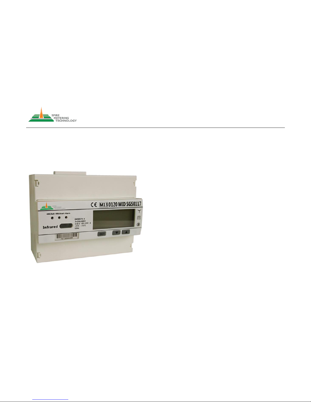
Smart energy meter
103EM series
Benefits and Features
● Three phase meter, 7 DIN modules, Standard DIN rail Format (DIN43880)
● IEC62053-21/22 Class 1.0,0.5S
● Record bi-directional active energy and 4-quadrant reactive energy for the last 12
months
● Records MD and its occurrence time for the last 12 months
● Instant Volt, Amp, Power factor, Frequency, Active power, Reactive power, Apparent
power
● TOU of 4 tariffs, up to 12 time periods per day
● Summer time switch
● load profile(option)
● Optional miniature load control relay for remote disconnect/reconnect
● Tamper-proof with terminal cover open detection (option)
● Direct metering up to 100A. CT version is available
● Clock time verification function
● Isolate pulse output (DIN43864)
● LCD display, 6 integer 2 decimal, meter display when power fails
● Large clear backlight display
● Optional single-phase model
● IR port and RS485 communication port, support Modbus protocol
● RF radio interface, 433MHz/868MHz (optional)
● Program by pressing button on the front panel
● Memory back-up (EEPROM)
● CE approval

User Manual 103EM series
Document code: UM103EM-737-1.1 Revision2.002
2
Index:
1. Safety notice
2. Content of delivery
3. Technical description
3.1 Survey of types/Ordering numbers
3.2 Performance criteria
3.3 Meter specification
4. Dimensions and sealing points
5. Wiring diagrams
6. Meter reading
7. Main function
7.1 Measuring Function
7.2 Demand function
7.3 Data store function
7.4. TOU function
7.5 Electricity parameters measurement and monitoring
7.6 Display function
7.7 Switching off display
7.8 Load record
7.9 Load control
7.10 Summer/winter time switch permit/prohibition
7.11 Communication Function
7.12 Alarm function
7.13 output function
7.13.1 Active/reactive pulse output
7.13.2 Multi-functions signal output
8 Programming
8.1 Password verify
8.2 CT rate setting
8.3 Baud rate setting
8.4 Address setting
9 Battery replacement
10 Technical support
User Manual 103EM series
Document code: UM103EM-737-1.1 Revision2.002
3
1. Safety notice
The 103EM series smart energy meter does not require special mechanical or
electrical tools for the installation. Mounting position (with any angle of tilt) has no
effect on the measurement functions of the meter.
Please note that meter wiring must be made according to applicable wiring diagram.
Incorrect connection of the meter to the electricity network could cause major display
problem and serious damage to the meter. Before starting the meter operation, it must
be ensured that the local conditions of the energy system are consistent with the data
shown on the nameplate of the meter. For the communication cables, it is preferred to
use shielded ones. Make sure that the cables are not damaged and free of
non-mechanical stress when installing. Also make sure that the meter is not energized
during meter installation.
Repairs or removing the meter cover can be made only by a qualified electrician who is
familiar with the associated risks. Capacitors in the meter may still be charged even if
the meter is disconnected from all energy sources
2. Content of delivery
Three phase electronic energy meter, instructions for assembly
ID setting
Baud rate setting
CT rate setting
Password setting
3. Technical description
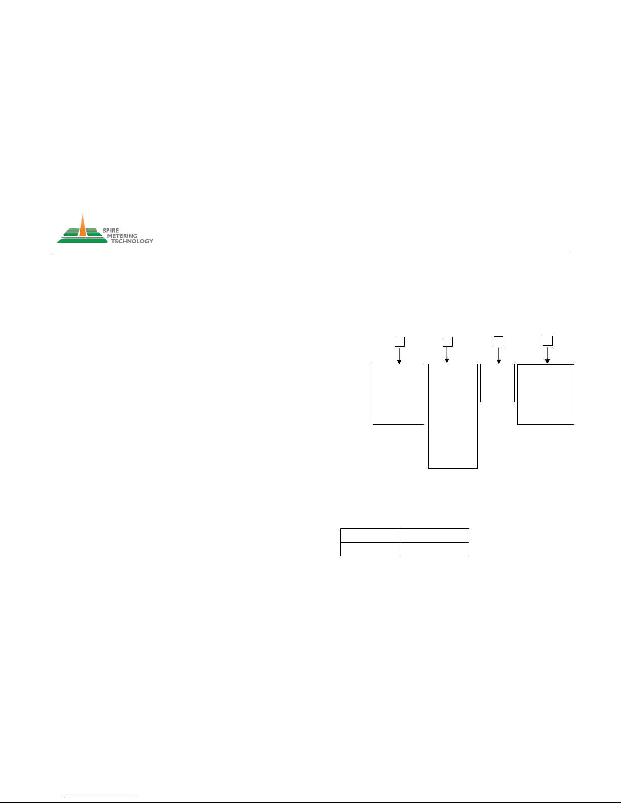
3.1 Identify model number and type
The model number of the 103EM series is defined as following:
103EM - - - -
103EM comes with two connection types: direct connection type and transformer
connection type. Please check the firmware version number (refer to section 7.2) and
use the following table to figure out which type your meter is.
735.1.1
Directly connect
735.2.1
Transformer connect
Output Interface
1) Pulse
2) RS485/Modbus
3) Other, please
specify
Relay
N) None
Y) Yes
Nominal
Voltage
A) 380VAC
B) Other,
please specify
Max Rated
Current
1) 40A
2) 100A
3) 200A
4) 400A
5) 800A
6) 1000A
7) 1500A
8) 2000A
9) 3000A
10) 4000A
11) 5000A
User Manual 103EM series
Document code: UM103EM-737-1.1 Revision2.002
4
3.2 Performance criteria
Operating humidity ≤ 75%
Storage humidity ≤ 95%
Operating temperature -5°C - +45°C(3K5)
Storage temperature -25°C - +55°C(3K6)
Humanity 75% yearly average,95% on 30 days/year
International standard EN50470-3&IEC62053-21
Accuracy class CI.1
Protection against penetration of dust and waterIP51
Insulating encased meter protective class Ⅱ
Connection area main terminals
Current terminals flexible 1×mm2 0-16mm
2
another terminal flexible 1×mm20-2.5mm
2
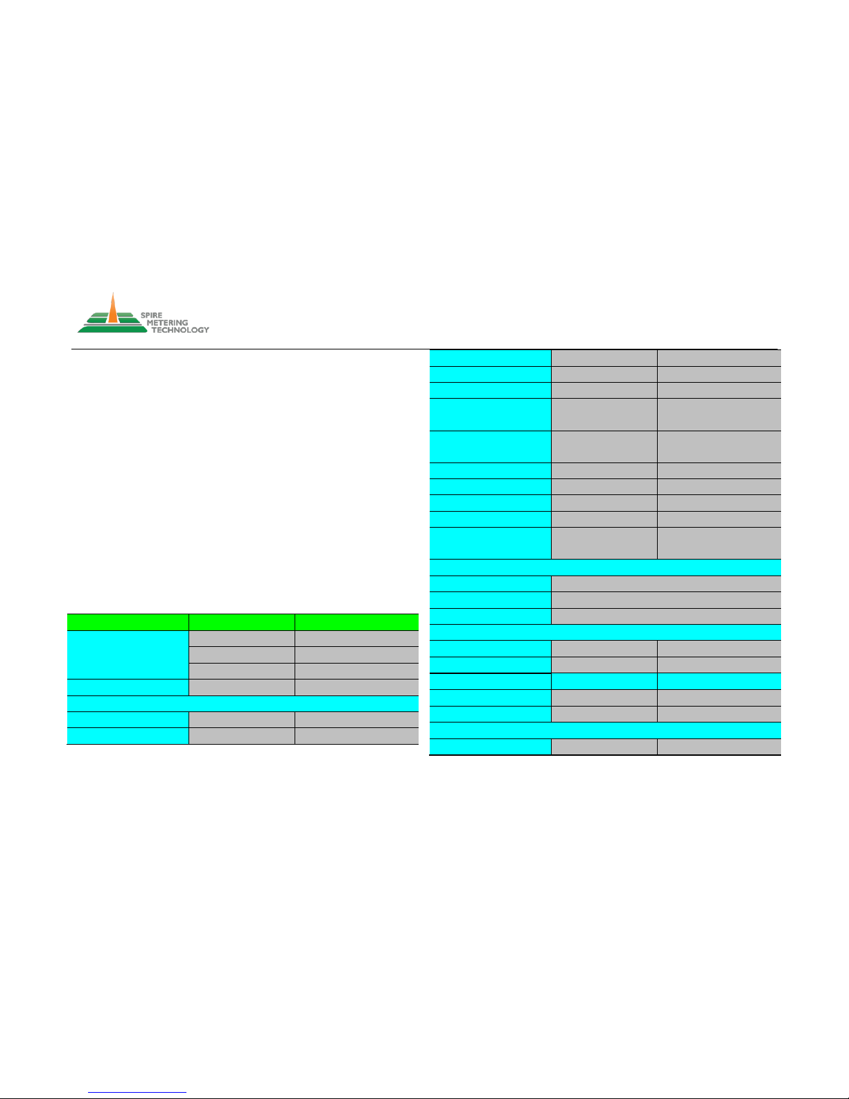
3.3 Meter specification
Direct connected meters
Transformer connected meter
Voltage(v)
3×57.7/100V
3×57.7/100V
3×220/380V
3×220/380V
3×230/400V
3×230/400V
Operational voltage
±70%Un
±70%Un
Current(A)
- Iref
10A
1.5
-Itr
1A
0.15A
-Imax
100A
6A
-Imin
0.5A
0.015A
-Ist
40mA
3mA
Power consumption of
current circuits(VA)
< 0.01
< 0.01
Power consumption of
voltage circuits(W)
< 1.3W
< 1.3W
General data
Frequency (Hz)
50/60
50/60 Direct connection type
Transformer connection type
Memory back-up
EEPROM
EEPROM
Environment resistance to
heat and fire
Terminal 960℃
Cover 650℃
Terminal 960℃
Cover 650℃
Internal real-time clock with battery
Time-keeping accuracy
<0.5s/day
Clock operating with battery
>15 years
Power off clock running time
>5 years
Enclosure material
upper
ABS+PC
ABS+PC
lower
ABS+PC
ABS+PC
Pulse output
Pulse width(ms)
80
80
Pulse constant(imp/kWh)
400
1600
LED
LED constant
400
1600

User Manual 103EM series
Document code: UM103EM-737-1.1 Revision2.002
5
Relay
Max junction voltage
AC250V DC30V
Max junction current
3A
Battery
Battery volume
1200mAh
Battery life
≥3years
Width (mm)
126
126
Height (mm)
104.5
104.5
Depth (mm)
60
60
4. Dimensions and sealing points
5. Wiring diagrams
Note: the following wiring diagram shows the energy meter with pulse output and
the RS-485 interface. For other outputs, please contact support@spiremt.com for
details.
Please note that the relay output is a miniature switch. It cannot be connected to
power line directly. You must use an external smart switch and an external relay
to provide remote connect/disconnect function.
5.1 Direct connection type meter
5.1.1 Pulse output diagram
 Loading...