

Page 1
IM-S27-12 CH Issue 1 1
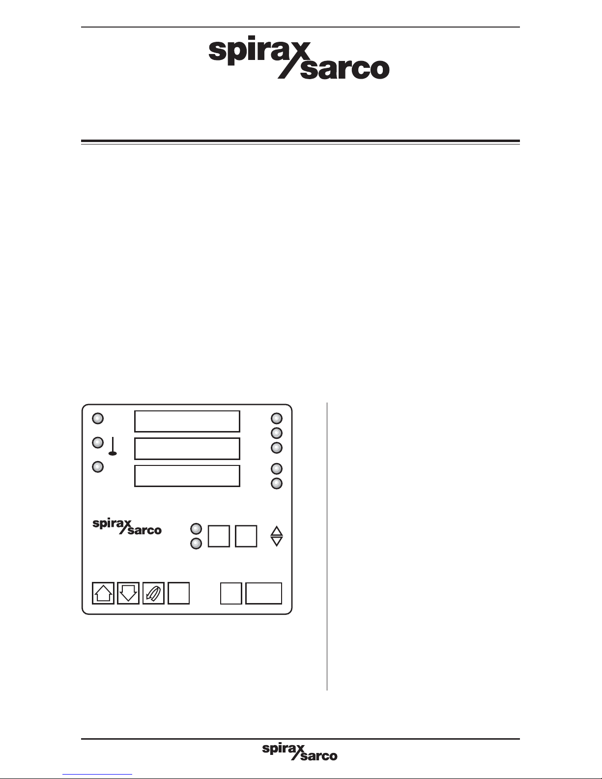
SX100e Controller
Quick Set-up Manual
Installation and Maintenance Instructions
IM-S27-12
CH Issue 1
2230054/1
1. Introduction
2. General
product information
3. Controller modes
4. Selecting, defining,
running and stopping
a program
5. SX100e
Commissioning
instructions
6. Record of settings
Printed in the UK
© Copyright 2003
AT
MAN
82
EV1
EV2
EV3
RUN
HLD
SET
PRG
MODE
PROG RUN\ STOP
67
65
pow:
50%
SX100e
Page 2
IM-S27-12 CH Issue 12
1. Introduction
Note: This manual should be read in conjunction with the standard SX100 Operator's
and Site manuals
The SX100e is a development of the SX100 controller with enhanced features, which have
been incorporated to simplify and improve the programming and operation of the controller,
particularly when used with heat exchange packages.
The differences in specification and operation of the SX100e in comparison to the SX100 are
outlined below.
AT
MAN
82
EV1
EV2
EV3
RUN
HLD
SET
PRG
MODE
PROG RUN\ STOP
67
65
pow:
50%
SX100e
2. General product information
2.1 Front facsia
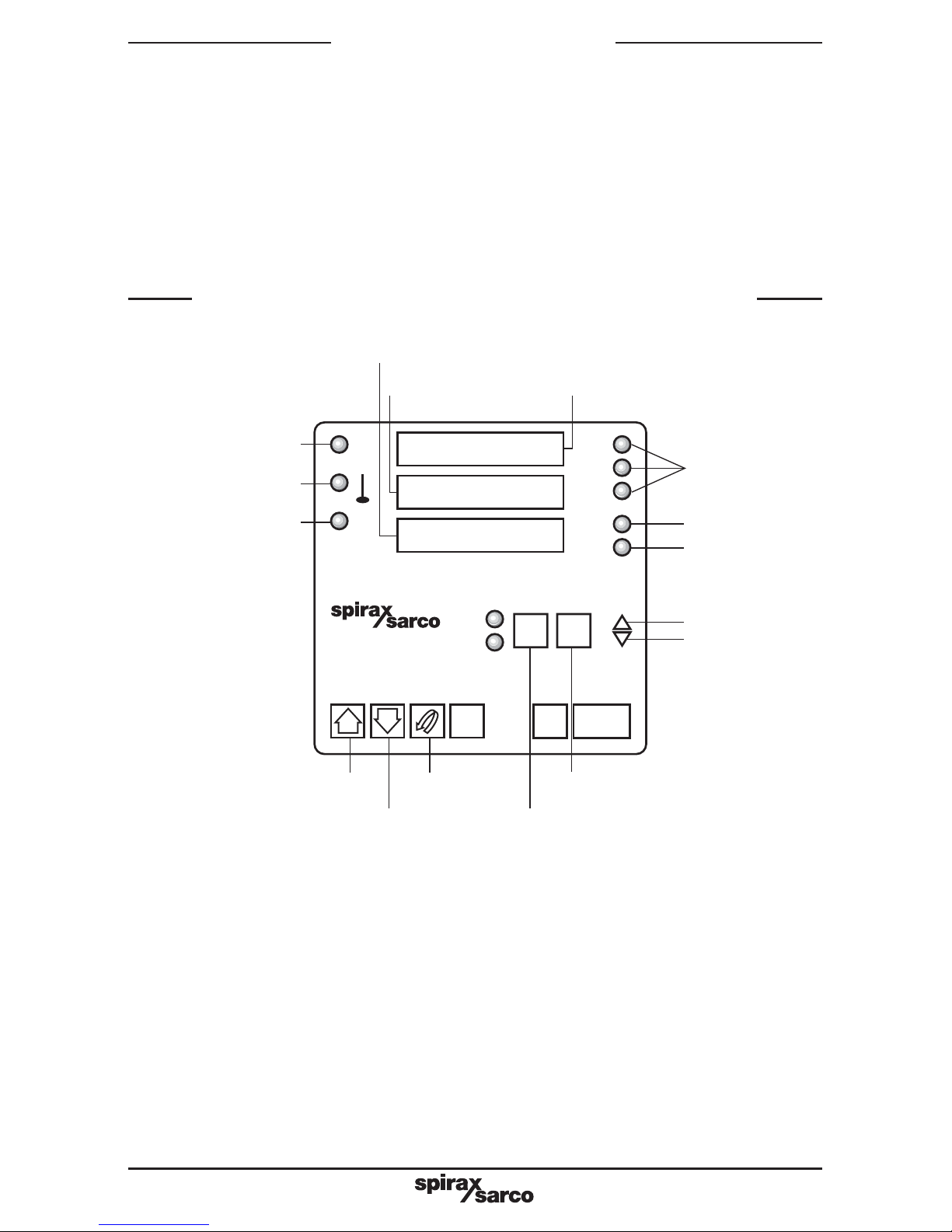
1. In the top left of the controller front there are now only three LED's instead of five - these are:
- AT - indicating if auto tune is active
- Thermometer Symbol - showing that Alarm 2 is active (EasiHeat bypass valve energized)
- MAN - indicating if the controller is in manual mode
2. The 'PROF' button has been renamed 'PROG'
3. The 'RUN/HOLD' button has been renamed 'RUN/STOP' as it more accurately describes its
new function.
4. In the top right of the controller front there are now only three LED's instead of four - these
are:
EV1 -Pump output
EV2 - Alarm 1 active - EasiHeat volt-free contact for remote high temperature alarm indication
EV3 -Loop Alarm active
Fig. 1
Message display
Lower display Upper display
Event LED's
Run LED
Hold LED
Ramp up LED
Ramp down LED
Segment
number
Program
number
Down
button
Up
button
Scroll
button
Auto tune LED
Alarm 2 active
(EasiHeat bypass valve)
Manual LED
Page 3

IM-S27-12 CH Issue 1 3
2.2 Functional changes
1. The creation of two security levels (note that to enter from Base Mode it is necessary on
the SX100e to press the PROG and UP buttons together before entering the appropriate
security code):
Level 1 security code (Factory set to 10 and not changeable)
Allows access to:
- Operator Edit mode
This is best used for day - to - day changes to program run times etc. Only the basic
temperature selection and running times are available in this mode, which simplifies any
alterations, reducing the possibility of mistakes being made.
Level 2 security code (Factory set to 100 and not changeable)
Allows access to:
- Operator Edit Mode
- Controller Define Mode
- Program Define Mode
This is for engineers and more experienced personnel who have sufficient expertise to
alter the major settings within the controller such as PID and hardware options etc.
2. Real time clock now works in actual time, not elapsed time from the start of a program.
3. Digital Input Board now fitted as standard
4. Linear Output Board now fitted as standard (to output 3). Note - this replaces the relay output
on the SX100.
It is vital when substituting an SX100e for an SX100 - that any power supply
connection to terminals 10, 11, or 12 are removed first - otherwise the controller
will be severely damaged. (Output 2 on the SX100e can be used instead of Output
3 on the SX100).
5. Output power is now continually shown on the controller display, expressed as a percentage
(unless the controller is in one of the programming modes)
6. The 'Control setpoint' on the SX100 has now been renamed 'Fallback' temperature for the
SX100e. This is now only available for configuration in CONTROLLER DEFINE mode.
This is the temperature the controller will attempt to maintain should the process value fall
below this level, even if a program is not running. This should normally be set to zero or no
more than 5 deg C, otherwise it may override a running program, or allow the control valve
to open at times when the heating should not be active.
7. 'Final Setpoint' is now renamed 'Target Set Point'
8. There are now three effective external options for the controller. Refer to Table 1 page 4.
Page 4

IM-S27-12 CH Issue 14
edoMnoitpircseD
TUO
edomenola-dnatS
.yltnednepedniskrowrellortnocehT
HTOB
)TUPNINUR(92lanimrete001XSotkcabdeefhtiw-edomenola-dnatS
gnitaehehtpmarotdesuebnacnoitcnufsihtnehtdesusirellortnoctimilhgihafI
lliwe001XSeht,timilhgihehtgnitteserretfA.sruccopirttimilhgihanehwnwod
.yllacitamotuatnioptesotpugnipmar,gnitaehehttratserneht
rohctiwswolfyasfokcabdeefhtiwnoitcnujnocnidesueboslanacerutaefsihT
.detacidnisiwolfretawonfismargorpfogninnurehttibihniot,tupnigninnurpmup
.margaiDgniriWtaeHisaEetairporppaotrefeR
SMB
rellortnocfolortnocmetsyStnemeganaMgnidliuB
rohctiwswolfyasfokcabdeefhtiwnoitcnujnocnidesueboslanacerutaefsihT
.detacidnisiwolfretawonfismargorpfogninnurehttibihniot,tupnigninnurpmup
.margaiDgniriWtaeHisaEetairporppaotrefeR
ENON
edomenola-dnatS
.'TUO'otlacitnediyllaitnessE
.daetsni'TUO'esu-secnatsmucriclamronnidesuebtondluohssihT
Table 1 Hardware configuration - external options
*
*
*
9. The SX100e has only two heating programs offered when running in each of the stand alone
modes:
- PROG 1 - TIMED
- PROG 2 - CONTINUOUS
10. Each program now has only three segments. These are:
- SEGMENT 1 RAMP UP
- SEGMENT 2 DWELL (MAINTAINS TEMPERATURE AT TARGET SET POINT)
- SEGMENT 3 RAMP DOWN (TO FINAL SET POINT)
11. In BMS mode - only programs 2 to 8 are available. These can be configured for temperatures
and ramp times, but heating start and heating finish control is from the external building
management system.
12. If power to the controller is switched off and then subsequently turned back on, any program
which is set to run at that time will re-start automatically and ramp up to the target set
point.
13. If External option is set to 'BOTH' a feedback to the run input on the controller can be used
to terminate a program should, for instance the circulating water pump fail. When the
feedback signal is re-established the program will then ramp back up to the target set point.
14. When changing from one program to another in stand alone or in BMS mode, the set point
temperature will ramp up or down as appropriate to the new value. It is not now necessary
to stop running the current program before changing to the next.
Note: there may be a delay of up to a minute before the program starts automatically
Page 5

IM-S27-12 CH Issue 1 5
15. If changes have been made to parameters in either of the CONFIGURATION MODES,
then when returning to BASE MODE, four LED dots may appear on the upper display
beneath the main digits.
This indicates that the configuration changes have now invalidated any previously set up
parameters in Program Define mode.
No programs will be able to run until changes have been made in Program Define or
Operator Edit modes.
The 4 LED dots will then disappear showing that the operator has recognized this
condition and taken the appropriate action.
3. Controller modes
The programmer has four operating modes (plus normal configuration mode and hardware
configuration mode):
Base Mode Display status - RUN, SET, PRG indicators Off.
(No security level) No program is running in this mode
Operator Edit Mode
Display status - 'Op.Edit' message
(Security level 1 or 2)
Program Run Mode Display status - RUN, EV1 indicators on
(Security level 2) Selected Program running
Program Define Mode Display status - 'Def.Prog' message
(Security level 2) Used to view and edit programs
Controller Define Mode Display status - 'Def.Ctrl' message
(Security level 2) Used to define the controller characteristics
Configuration Mode
Display status - 'Conf' message
(Config. security code)
Additional information and details of factory settings when used for the EasiHeat application are
detailed in the following sections
Page 6
IM-S27-12 CH Issue 16
4. Selecting, defining, running
and stopping a program
:edomesabmorfretneoT
sserP GORP dna PU )deyalpsidsiegassem'drowssaP'(rehtegot
esU PU ro NWOD edocytiruceS2leveLro1leveLrehtietcelesotnottub
sserP LLORCS nottub
noitpircseD
egasseM
yalpsid
egnareulaV
yrotcaF
gnittes
n
ielibaliavA
ytiruces
level
12
ybmargorpetairporppatceleS
nottubGORPehtgnisserp
.onmargorpderiuqerehtlitnu
ehtnideyalpsidsidetideebot
TESehtottnecajdawodniw
)s'delGRPdna
2ot1
2ot1
=noitpotxEfi(
)'htob'ro'tuo'
8ot2
)'smb'=noitpotxEfi(
A/NseYseY
ehtsserP:edoMtidErotarepOmorftixeoT EDOM edomderisedehtlitnuyldetaepernottub
sserpnehT'ESAB'.g.e,deyalpsidsiegassem LLORCS .
4.1 Selecting a program
In order to change the selection of a program when the SX100e is operating as a stand-alone
controller, it is necessary to enter 'OPERATOR EDIT' mode.
If it is necessary only to change the program selected, refer to Table 2 below.
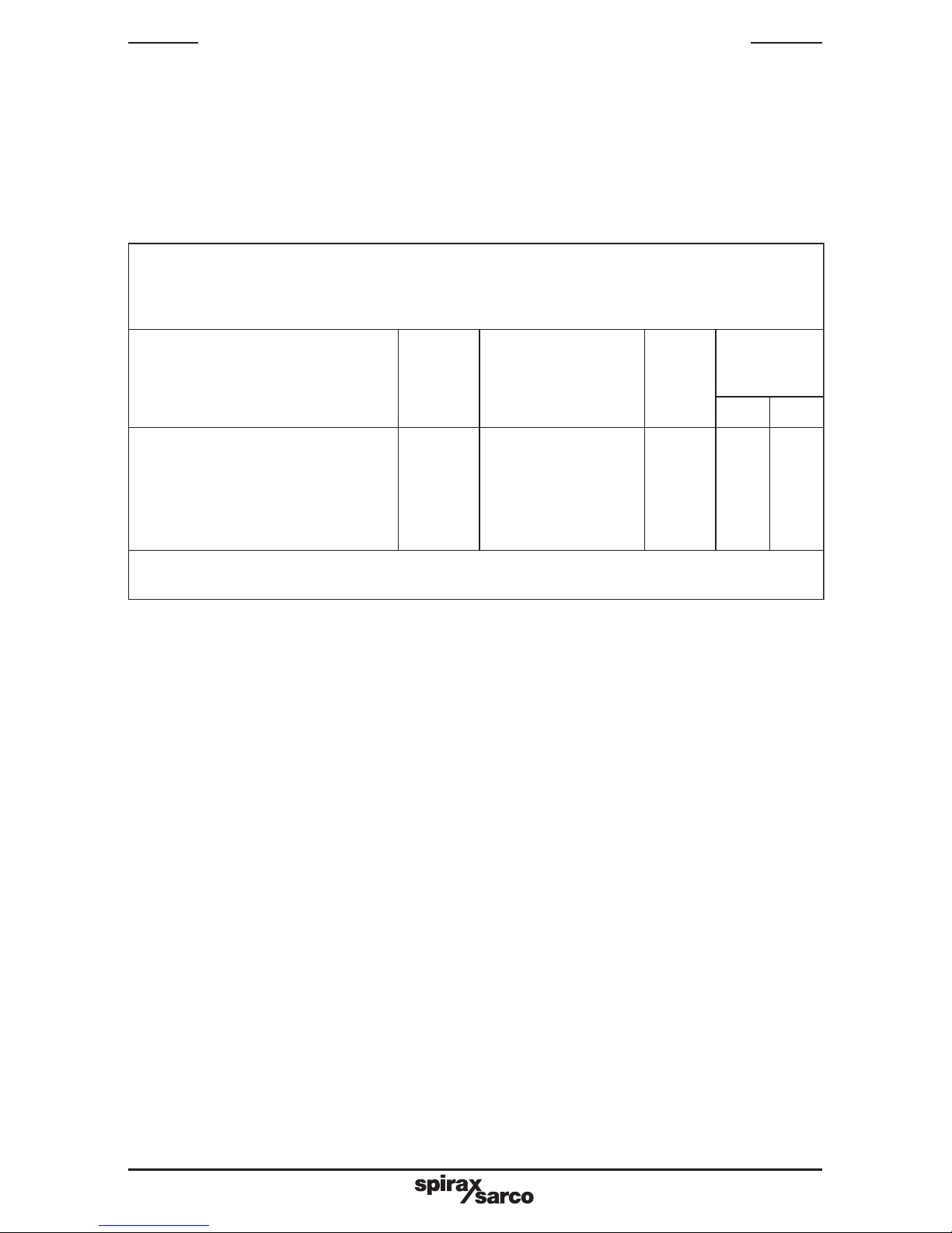
Table 2 SX100e Operator edit mode
4.2 Defining a program
Follow the instructions on Table 3 below to select a new program, and/or to change the
parameters of the required programs as indicated.
Page 7

IM-S27-12 CH Issue 1 7
:edomesabmorfretneoT
sserP GORP dna PU )deyalpsidsiegassem'drowssaP'(rehtegot
esU PU ro NWOD edocytiruceS2leveLro1leveLrehtietcelesotnottub
sserP LLORCS nottub
noitpircseD
egasseM
yalpsid
egnareulaV
yrotcaF
gnittes
n
ielibaliavA
ytiruces
level
12
etairporppatceles-yltsriF(
GORPehtgnisserpybmargorp
deriuqerehtlitnunottub
sidetideebot.onmargorp
wodniwehtnideyalpsid
GRPdnaTESehtottnecajda
)s'del
2ot1
2ot1
=noitpotxEfi(
)'htob'ro'tuo'
8ot2
)'smb'=noitpotxEfi(
/NA seYseY
tnioPteStegraT PStegraT003ot0 °C56seYseY
emiTtratSmargorP tatratS95:32ot00:000.80seYseY
emiTdnEmargorP tadnE95:32ot00:000.71seYseY
syadnurmargorP
nuR
syaD
,seuT,noM,nuS
,taS,irF,uhT,deW
,)irF-noM(yd5
,)taS-noM(yd6
)keewasyaD7(LLA
yd5seYseY
noitcnufemitteS ?emiTteSoN,seY/NA seYseY
sujdAt/ gnitteSemiTkcehc emiT95:32-00:0/NA seYseY
sujdAt/ keewfoyadkcehc yaD
,seuT,noM,nuS
taS,irF,uhT,deW
/NA seYseY
tidErotarepOmorftixeoT
nottubEDOMsserPedoM
deriuqerehtlitnuyldetaeper
sserpneht,deyalpsidsiedom
nottubLLORCS
elddiM
-yalpsid
otoG
rewoL
-yalpsid
edoM
esaB,tidE,pO
,gorP.feD,lrtC.feD
/NA
seY
oN
seY
seY
ehtsserP:edoMtidErotarepOmorftixeoT EDOM edomderisedehtlitnuyldetaepernottub
sserpnehT'ESAB'.g.e,deyalpsidsiegassem LLORCS .
Table 3 SX100e Operator edit mode
4.3 Running a program
Program 1 (timed) - if the controller is set to run on the current day and time, the program
will start automatically once the controller has been switched on
(there may be a delay of up to a minute for this to happen after initial
power up)
Program 2 (constant) - having selected program 2, it is necessary to press the RUN/STOP
button once.
Page 8

IM-S27-12 CH Issue 18
4.4 Overriding a program
In program 1 (timed) or program 2 (constant) the program can be started or stopped by using the
RUN / STOP button.
Program 1 - (Timed)
Stopping Program 1:
- If program 1 is running, it can be stopped by pushing the RUN/STOP button for approximately
5 seconds.
- The segment no. will then change to '3' and the target temperature will be seen to ramp down,
before finally terminating.
- The RUN LED will then go off.
- The program will then restart at the next scheduled start time.
Starting Program 1:
- If program 1 is not running, it can be started by pushing the RUN/STOP button briefly.
- Segment no. 1 will then be indicated on the display.
- The RUN LED will then illuminate and desired temperature will be seen to ramp up towards
the target temperature.
- When target temperature is reached , the segment no. will change from 1 to 2.
- The program will then stop at the next scheduled stop time.
Program 2 - (Constant)
Stopping Program 2 :
- If program 2 is running, it can be stopped by pushing the RUN/STOP button for approximately
5 seconds.
- The segment no. will then change to ‘3’ and the target temperature will be seen to ramp down,
before finally terminating.
- The RUN LED will then go off.
- The program will NOT restart until the RUN/STOP button is pressed again.
Starting Program 2:
- If program 2 is not running, it can be started by pushing the RUN/ STOP button briefly.
- Segment no. 1 will then be indicated on the display.
- The RUN LED will then illuminate and desired temperature will be seen to ramp up towards
the target temperature.
- When target temperature is reached , the segment no. will change from 1 to 2.
- The program will then continue running.
Page 9
IM-S27-12 CH Issue 1 9
5. SX100e Commissioning
instructions
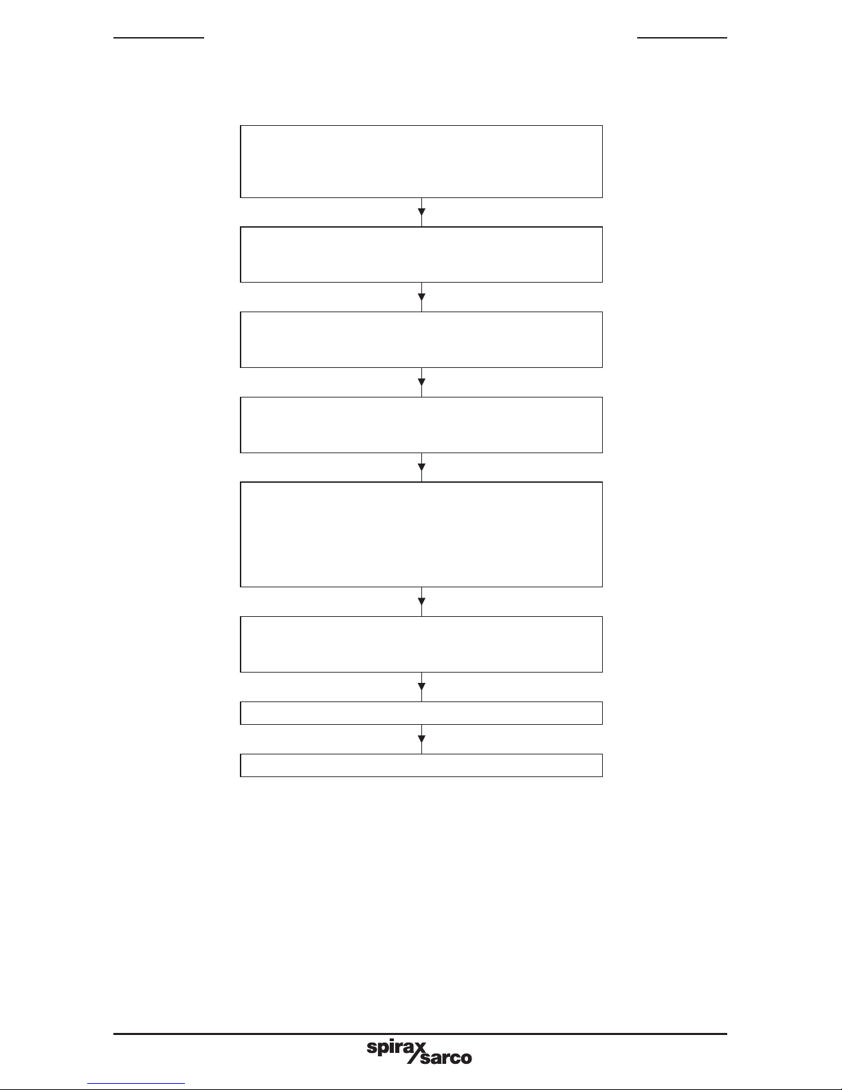
Go to 'normal' configuration mode
(ref. section 5.1)
then before making changes in this mode, go to
hardware configuration mode
Go to program define mode
(ref. section 5.5)
make changes to parameters as required
If 4 dots appear on the upper display -
this indicates that changes to configuration above
have invalidated any program define settings
previously made.
if so, check all program define parameters below
and adjust as necessary
Go to controller define mode
(ref. section 5.4)
make changes to parameters as required
Return to 'normal configuration mode
(ref. section 5.3)
make changes to parameters as required
Hardware configuration mode
(ref. section 5.2)
make changes to parameters as required
Go to base mode
Controller is now ready for use
Fig. 2 Initial commissioning sequence
Follow the steps below (5.1 to 5.5) to ensure that controller is configured correctly. (Each table
describes how to enter and exit from the appropriate mode)
5.1 Normal configuration
-
Table 4 - 'Normal' configuration mode parameters.
(N.B. - If changes are to be made to hardware configuration, do these first. otherwise the
expected options may not be displayed – ref. 5.2 below)
Page 10

IM-S27-12 CH Issue 110
5.2 Hardware configuration:
- Table 6 - hardware configuration parameters.
Reference:
- Diagram 3 - sx100e hardware definition code.
- Diagram 4 - sx100e external options.
- Diagram 5 - digital inputs.
5.3 Return to normal configuration:
- Table 4 - 'normal' configuration mode parameters
Reference:
- Table 5 - primary input ranges.
5.4 Controller define:
- Table 8 - controller define parameters.
5.5 Program define:
- Table 9 - program define parameters.
Page 11

IM-S27-12 CH Issue 1 11
:edomnoitarugifnoclamronretneoT
.nokcabnehtdnafforewopnruT
sserP LLORCS dna PU reppuni'FnoC'wohsotsegnahcyalpsidehtlitnudlohdnasnottub
.yalpsid
sserpnehT LLORCS .wolebtsilehthguorhtevomotnottub
( etoN ehtgnisserpybdetpeccaebotevahsegnahcynataht EDOM :)nottub
noitpircseD
egasseM
yalpsid
noitcnuF
sgnitteselbaliavA
seulavdna
)yalpsidniamrewoL(
yrotcaF
gnittes
tupniyramirP
egnar
tupnI
edoCdeyalpsiD
epyttupnisenifed
egnardna
woleb5elbaT.feR 1522
lortnoC
noitca
lortnoC
lortnocseificepS
1tuptuOfonoitca
esreveRdradnatS-rdTS
gnitca
rdtS
epyt1mralA 1mralA
1mralAseificepS
noitarepo
iH_P hgiHssecorP-
oL_P woLssecorP-
Ed noitaiveD-
dnab dnaB-
enon enoN-
dnAb
epyt2mralA 2mralA
2mralAseificepS
noitarepo
iH_P hgiHssecorP-
oL_P woLssecorP-
Ed noitaiveD-
dnab dnaB-
enon enoN-
Ed
tibihnimralA tibihnI
ehtstibihnI
)s(mraladeificeps
pupmargnirud
nwodpmardna
)3dna1stnemges(
enon tibihnIoN-
1ALA 1mralA-
2ALA 2mralA-
htob smralAhtoB-
enon
2tuptuO
egasu
esU2tuO
foegasuseificepS
2tuptuO
d_2A )tcerid(2mralA-d_2A
3tuptuO
egasu
esU3tuO
foegasuseificepS
3tuptuO
enon noissimsnart-eron-
Pcer fonoissimsnart-er-
eulaVssecorP
)VP(erutarepmet
Scer fonoissimsnart-er-
tnioPteStegraT
)PS(erutarepmeT
enon
e
lbaT.feroslA(
margaiDdna6
)woleb2
fodnE
yalermargorp
yalerPOE
dnEnehwstceleS
yaleRmargorPfo
desigrenesi
noelbaegnahcton-dnE
e001XS
dnE
etarduaB etaRduaB
etaRduaBstceleS
584SRrof
snoitacinummoC
0021
0042
0084
0069
0084
:edoMesaBotkcabedoMnoitarugifnoCmorftixeoT
sserP PU dna LLORCS
)
edomESABotnruterdnatrats-erlliwrellortnoceht(rehtegotsnottub
Table 4 SX100e normal configuration mode
Page 12
IM-S27-12 CH Issue 112
Table 5 Primary input ranges (normal configuration mode)
Resistance temperature detector (rtd) dc linear input range
Input range Displayed code Input range Displayed code
32 - 571 °F 2229 0 - 50 mV 4443
-100.9 - 100.0 °C 2230 10 - 50 mV 4499
-149.7 - 211.9 °F 2231
0 - 300 °C* 2251*
0.0 - 100.9 °C 2295
32 - 213.6 °F 2296
-200 - 206 °C 2297
-328 - 402 °F 2298
0 - 800 °C 7220
32 - 1 472 °F 7221
-100.9 - 537.3 °C 7222
-149.7 - 999.1 °F 7223
* Default setting
Table 6 SX100e hardware configuration mode (ref Figure 3)
sserP.)4elbaT.feR(edomnoitarugifnocmorF:edomnoitarugifnocerawdrahretneoT
tsilehthguorhtevomotnottubLLORCSesunehT.rehtegotsnottubnwoddnallorcs
:)nottubEDOMehtgnisserpybdetpeccaebotevahsegnahcynatahteton(woleb
noitpircseD
egasseM
yalpsid
noitcnuFgnittesyrotcaF
erawdraH
edocnoitinifed
3erugiF.feR
woleb
enifedwHA/N
0171
:otsetauqesihT
=tupnI 1
.
001tP=)rosneserutarepmetssecorp(
=1tuptuO 7
.Am02-4=)tuptuolortnoc(
=2tuptuO 1 .yaler=)2mrala(
=3tuptuO 0
r
oeulavssecorpfonoissimsnart-er(
.detceleston=)tnioptes
sadettifsidraobnoissimsnart-eR
sidna3tuptuonodradnats
.esurofelbaliava
snoitpolanretxE
dna1elbat.feR
4margaid
ntpotxE
,tuo,*enon
smb,htob
fodaetsni'tuo'esu(
)e001XSno'enon'
tuo
snoitacinummoC smmoc,enon SAM,ALS
enon
t
onsidraobnoitposnoitacinummoc(
)dradnatssadettif
epytstupnilatigiD
fielbisivylno.B.N(
nidetcelessmb
)snoitpolanretxe
stupnIltt,tnoc
tnoc
)sehctiws.e.i-stcatnoc(
NWODsserP:edoMnoitarugifnoCotkcabedoMnoitarugifnoCerawdraHmorftixeoT
.rehtegotnottubLLORCSdna
Page 13
IM-S27-12 CH Issue 1 13
Input type
(Process temperature sensor
)
1 = RTD/Linear DC (mV)
Output 1 type
(Control output)
3 = DC (0-10 V)
4 = DC (0-20 mA)
5 = DC (0-5 V)
7 = DC (4-20 mA)
Output 3 type
(Re-transmission)
0 = Not selected
3 = DC (0-10 V)
4 = DC (0-20 mA)
5 = DC (0-5 V)
7 = DC (4-20 mA)
Output 2 type
(Relay)
0 = Not selected
1 = Relay
Fig. 3 SX100e hardware definition code (default value is 1710 as indicated)
1 7 1 0
none* out both BMS
Controller in
Stand alone mod
e
Digital input board
fitted but not
utilized for control
Relay output board
fitted and used for
Events 1, 2 and 3
Controller in
Stand alone mod
e
Digital input board
fitted but not
utilized for control
Relay output board
fitted and used for
Events 1, 2 and 3
Controller in
Stand alone mod
e
Digital input board
fitted but not
utilized for control
by BMS
Relay output board
fitted and used for
Events 1, 2 and 3
Run/stop input on
SX100e terminal
29 can be used to
inhibit program
Run (e.g. in no
secondary water
flow situation and /
or high limit trip)
Controller in
BMS mode
Digital input board
fitted and can be
used for control by
BMS system
Relay output board
fitted and used for
Events 1, 2 and 3
Run/stop input on
controller terminal
29 can be used to
inhibit program
Run (e.g. in no
secondary water
flow situation and /
or high
temperature trip)
Ext Opt
n
Fig. 4 SX100e External options
* Use 'out' instead. ('None' is not normally used on the SX100e)
Page 14
IM-S27-12 CH Issue 114
Inputs
ttl
Digital inputs
TTL level inputs
cont
Digital inputs
Contact (switches
)
(Default setting)
The programs are selected as described in Table 7 below.
The input combinations on R0, R1, R2, decide the program that will run.
Note that when there are no inputs to these terminals, the program will halt.
Table 7 SX100e BMS program selection chart
(Note – this is different to the SX100. Also Prog 1 is not available in BMS mode on the SX100e )
Fig. 5 Digital inputs
)1cigol=1,0cigol=0('ltt'=stupnI )nepo=O,desolc=C('tnoc'=stupnI
0R1R2RgorP0R1R2RgorP
000 tlaH OOO tlaH
1002 COO2
0103 OCO3
1104 CCO4
0015 OOC5
10 16 COC6
0117 OCC7
1118 CCC8
Page 15

IM-S27-12 CH Issue 1 15
:edomesabmorfretneoT
sserP GORP dna PU .)deyalpsidsiegassem'drowssaP'(rehtegot
esU PU ro NWOD .edocytiruceS2leveLtcelesotnottub
sserP LLORCS .)deyalpsidsiegassem'PStegraT'(nottub
sserP EDOM .)deyalpsiderasegassem'lrtC.feD'dna'otoG'(eciwtnottub
sserP LLORCS .nottub
noitpircseDyalpsidegasseMegnareulaVgnittesyrotcaF
erutarepmeTkcabllaF kcabllaF003-00
tuptuOrewoP rewoP%001-0A/N
enuTfleS enuTfleSFFO,NOFFO
)%(dnaBlanoitroporP dnaBporP001-00.21
emiTlargetnI
)sces/snim(
largetnIfni-021.0
emiTevitavireD
)sces/snim(
.vireD
fni-0
30.0
saiB saiB
otdeilppasaiB
rewoptuptuo
2
)%(timiLrewoPtuptuO hgiHtuO
levelrewopstimiL
1tuptuOfo
001
)C°(timiLhgiHtnioPteS hgiHPS
roftimilmumixaM
tnemtsujdatnioptes
001
)C°(timiLwoLtnioPteS woLPS
roftimilmuminiM
tnemtsujdatnioptes
0
)C°(eulav1mralA 1mralAlevelmralA)mraladnab(01
siseretsyH1mralA tsyH.1lAdnabsiseretsyH1
)C°(eulav2mralA 2mralAlevelmralA)mralanoitaived(2
siseretsyH2mralA tsyH.2lAdnabsiseretsyH1
emiTretliFtupnI
tnatsnoC
retliF
emitsenifeD
tupniroftnatsnoc
retlif
5.0
)C°(tesffO tesffO
derusaemfotesffO
eulav
0
kcoLmargorP gorPkcoL
'NO'detcelesfI
segnahcstibihnI
simargorpatslihw
gninnuryllautca
FFO
hgiHtuptuOredroceR
rofdesu3tuptuofI(
)C°()noissimsnart-er
hgiHceR001
fI(woLtuptuOredroceR
rofdesu3tuptuo
)C°()noissimsnart-er
woLceR0
:edoMenifeDrellortnoCmorftixeoT
ehtsserP EDOM .deyalpsidsiegassemedomderisedehtlitnuyldetaepernottub
sserpnehT .LLORCS
Table 8 SX100e controller define mode
Page 16
IM-S27-12 CH Issue 116
:edomesabmorfretneoT
sserP GORP dna PU )deyalpsidsiegassem'drowssaP'(rehtegot
esU PU ro NWOD edocytiruceS2leveLtcelesotnottub
sserP LLORCS )deyalpsidsiegassem'PStegraT'(nottub
sserP EDOM )deyalpsiderasegassem'gorP.feD'dna'otoG'(litnuyldetaepernottub
sserP LLORCS nottub
noitpircseDyalpsidegasseMegnareulaVgnittesyrotcaF
etarpupmaR (PU °C/ )mN/A 03
tnioptestegraT PStegraTN/A 01elbaT.feR
etarnwodpmaR (nD °C/ )mN/A 03
tniopteslaniF PSlaniFN/A N/A
syadnuR syaDnuR
,taS,irF,uhT,deW,euT,noM,nuS
llA,yd6,yd5,nuS
N/A
emittratS tatratS95.32ot00.000.8
emithsiniF tadnE95.32ot00.000.71
:edomenifedmargorpmorftixeoT
ehtsserP EDOM .deyalpsidsiegassemedomderisedehtlitnuyldetaepernottub
sserpnehT LLORCS .
Table 9 SX100e program define mode
noitpircseD
egasseM
yalpsid
rebmunmargorP
12345678
demiT
natsnoCt/
SMB
SMBSMBSMBSMBSMBSMB
etarpupmaR (pU °C/ )m0303030303030303
tnioptestegraT PStegraT5656565656565656
nwodpmaR
etar
(nD °C/ )m0303030303030303
tniopteslaniF PSlaniF0202020202020202
syadnuR syadnuRsyD5 N /A N /A N/A N /A N/A N/A N/A
emittratS tatratS00.8 N /A N /A N/A N /A N/A N/A N/A
emithsiniF tadnE00.71 N/A N /A N/A N/A N /A N/A N/A
hcihwnielbaliavamargorP
erawdraH(noitpOlanretxE
)noitarugifnoC
TUO
dna
HTOB
,TUO
HTOB
SMBdna
SMB
Table 10 SX100e factory default settings in program define mode
Page 17
IM-S27-12 CH Issue 1 17
egasseM
yalpsid
yrotcaF
gnittes
rebmunmargorP
12345678
PStegraT 56
tAtratS 00.8tsnoC
tadnE 00.71tsnoC
syaDnuR Yd5tsnoC
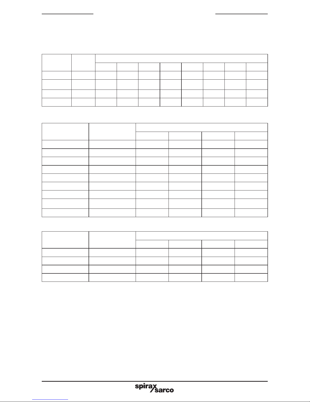
(All parameters should be recorded here when commissioning is complete, and when
any subsequent changes are made)
Table 11 Operator edit mode settings
Table 12 Normal configuration mode settings
yalpsidegasseMgnittesyrotcaF
gnitteslautcA
:etad:etad:etad:etad
tupnI 1522
lortnoC rdtS
1mralA DnAb
2mralA Ed
tibihnI enon
ESU2TUO d_2A
ESU3TUO enon
yaleRPOE DNE
etarduaB 0084
yalpsidegasseMgnittesyrotcaF
gnitteslautcA
:etad:etad:etad:etad
enifedwH 0171
ntpotxE tuO
smmoC enoN
stupnI tnoC
Table 13 Hardware configuration mode settings
6. Record of settings
Page 18

IM-S27-12 CH Issue 118
yalpsidegasseMgnittesyrotcaF
gnitteslautcA
:etad:etad:etad:etad
kcabllaF0
enutfleSFFO
dnabporP0.21
largetnI21.0
.vireD30.0
saiB2
hgihtuO001
hgihpS001
wolpS0
1mralA01
.tsyh1lA1
2mralA2
retliF5.0
tesffO0
gorpkcoLFFO
hgihceR001
wolceR0
Table 14 Controller define mode settings
Page 19
IM-S27-12 CH Issue 1 19
noitpircseD
egasseM
yalpsid
rebmunmargorP
12345678
demiT
natsnoCt/
SMB
SMBSMBSMBSMBSMBSMB
etarpupmaR (pU °C/ )m0303030303030303
tnioptestegraT PStegraT5656565656565656
nwodpmaR
etar
(nD °C/ )m0303030303030303
tniopteslaniF PSlaniF0202020202020202
syadnuR syadnuRsyD5 N /A N /A N/A N /A N/A N/A N/A
emittratS tatratS00.8 N /A N /A N/A N /A N/A N/A N/A
emithsiniF tadnE00.71 N/A N /A N/A N/A N /A N/A N/A
hcihwnielbaliavamargorP
erawdraH(noitpOlanretxE
)noitarugifnoC
tuO
dna
htob
htob,tuO
SMBdna
SMB
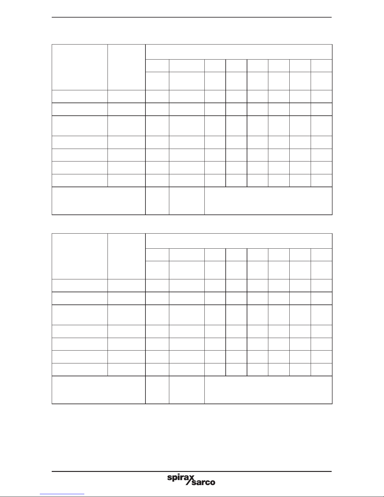
Table 10 SX100e factory default settings in program define mode
noitpircseD
egasseM
yalpsid
rebmunmargorP
12345678
demiT
natsnoCt/
SMB
SMBSMBSMBSMBSMBSMB
etarpupmaR (pU °C/ )m
tnioptestegraT PStegraT
nwodpmaR
etar
(nD °C/ )m
tniopteslaniF PSlaniF
syadnuR syadnuR N/A N /A N/A N/A N /A N/A N/A
emittratS tatratS N /A N /A N/A N/A N /A N/A N/A
emithsiniF tadnE N /A N /A N/A N /A N/A N/A N/A
hcihwnielbaliavamargorP
erawdraH(noitpOlanretxE
)noitarugifnoC
tuO
dna
htob
htob,tuO
SMBdna
SMB
Table 15 SX100e actual program define mode settings
Page 20

IM-S27-12 CH Issue 120
 Loading...