

Page 1
IM-P014-16 MI Issue 2
1
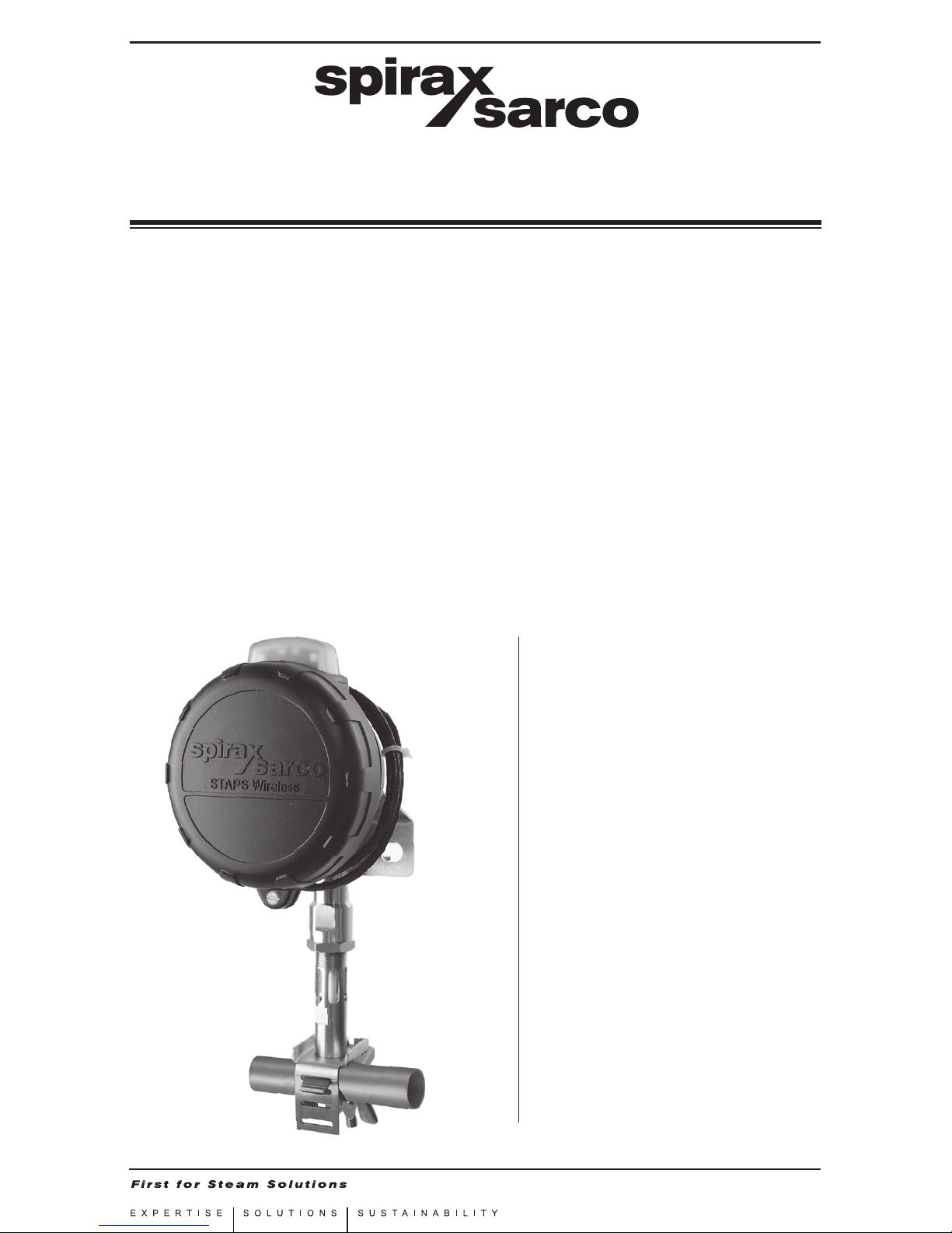
STAPS
Wireless Head Unit
Quick Installation Guide
1. Safety information
2. General product
information
3. Order of installation
4. Installation of head
5. Spare parts
6. Certication and
approvals
7. Technical data
8. Technical glossary
IM-P014-16
MI Issue 2
0140051/2
© Copyright 2015
Printed in GB
Page 2

IM-P014-16 MI Issue 2
2
Safe operation of this unit can only be guaranteed if it is properly installed,
commissioned and maintained by a qualified person (see Section 1.11) in compliance
with the operating instructions. General installation and safety instructions for pipeline
and plant construction, as well as the proper use of tools and safety equipment must
also be complied with.
Manufacturer - Spirax-Sarco Limited
,
Charlton House, Charlton Kings, Cheltenham, Gloucestershire, UK, GL53 8ER
The product is designed and constructed to withstand the forces encountered
during normal use. Use of the product for any other purpose, or failure to install the
product in accordance with these Installation and Maintenance Instructions, could
cause damage to the product, will invalidate the marking, and may cause injury or
fatality to personnel.
1.1 Intended use
Referring to the Installation and Maintenance Instructions, name-plate and Technical
Information Sheet, check that the product is suitable for the intended use / application.
i) The product has been specifically designed for use on saturated steam systems.
ii) Check material suitability, pressure and temperature and their maximum
and minimum values.
iii) Determine the correct installation situation and direction of fluid flow.
iv) Spirax Sarco products are not intended to withstand external stresses that
may be induced by any system to which they are fitted. It is the responsibility of
the installer to consider these stresses and take adequate precautions to
minimise them.
1.2 Access
Ensure safe access and if necessary a safe working platform (suitably guarded)
before attempting to work on the product. Arrange suitable lifting gear if required.
1.3 Lighting
Ensure adequate lighting, particularly where detailed or intricate work is required.
1.4 Hazardous liquids or gases in the pipeline
Consider what is in the pipeline or what may have been in the pipeline at some
previous time. Consider: flammable materials, substances hazardous to health,
extremes of temperature.
1.5 Hazardous environment around the product
Consider: explosion risk areas, lack of oxygen (e.g. tanks, pits), dangerous
gases, extremes of temperature, hot surfaces, fire hazard (e.g. during welding),
excessive noise, moving machinery.
1.6 The system
Consider the effect on the complete system of the work proposed. Will any proposed
action (e.g. closing isolation valves, electrical isolation) put any other part of the
system or any personnel at risk?
Dangers might include isolation of vents or protective devices or the rendering
ineffective of controls or alarms. Ensure isolation valves are turned on and off in a
gradual way to avoid system shocks.
1. Safety information
Page 3

IM-P014-16 MI Issue 2
3
1.7 Pressure systems
Ensure that any pressure is isolated and safely vented to atmospheric pressure.
Consider double isolation (double block and bleed) and the locking or labelling of
closed valves. Do not assume that the system has depressurised even when the
pressure gauge indicates zero.
1.8 Temperature
Allow time for temperature to normalise after isolation to avoid the danger of burns
and consider whether protective clothing (including safety glasses) is required.
1.9 Tools and consumables
Before starting work ensure that you have suitable tools and / or consumables
available. Use only genuine Spirax Sarco replacement parts.
1.10 Protective clothing
Consider whether you and / or others in the vicinity require any protective clothing to
protect against the hazards of, for example, chemicals, high / low temperature, radiation,
noise, falling objects, and dangers to eyes and face.
1.11 Permits to work
All work must be carried out or be supervised by a suitably competent person.
Installation and operating personnel should be trained in the correct use of the product
according to the Installation and Maintenance Instructions.
Where a formal 'permit to work' system is in force it must be complied with. Where
there is no such system, it is recommended that a responsible person should know
what work is going on and, where necessary, arrange to have an assistant whose
primary responsibility is safety.
Post 'warning notices' if necessary.
1.12 Handling
Manual handling of large and / or heavy products may present a risk of injury. Lifting,
pushing, pulling, carrying or supporting a load by bodily force can cause
injury particularly to the back. You are advised to assess the risks taking into account
the task, the individual, the load and the working environment and use the appropriate
handling method depending on the circumstances of the work being done.
1.13 Residual hazards
In normal use the external surface of the product may be very hot. If used at the
maximum permitted operating conditions the surface temperature of some products
may reach temperatures of 425°C (797°F).
Many products are not self-draining. Take due care when dismantling or removing the
product from an installation (refer to 'Maintenance instructions').
1.14 Freezing
This product does not contain fluid that will freeze, however lower temperatures
will affect the product performance. Do not subject the product to temperatures
below the stated minimum.
1.15 Disposal
Unless otherwise stated in the Installation and Maintenance Instructions, this
product is recyclable and no ecological hazard is anticipated with its disposal providing
due care is taken. The product should be recycled in line with local legislation. Special
attention should be paid to the battery, see section 1.17.
Page 4

IM-P014-16 MI Issue 2
4
1.16 Returning products
Customers and stockists are reminded that under EC Health, Safety and
Environment Law, when returning products to Spirax Sarco they must provide
information on any hazards and the precautions to be taken due to contamination
residues or mechanical damage which may present a health, safety or environmental
risk. This information must be provided in writing including Health and Safety data
sheets relating to any substances identified as hazardous or potentially hazardous.
Refer to section 1.17 with regards to shipping / returning of the lithium batteries.
1.17 Ba tte ry
The Head unit is powered by a Lithium battery (SAFT LS 33600 3.6 V cell).
Handling considerations:
- Do not crush, pierce, short (+) and (-) battery terminals with conductive (i.e. metal)
goods.
- Do not directly heat or solder.
- Do not throw into a fire.
- Do not mix batteries of different types and brands.
- Do not mix new and used batteries.
- Keep batteries in non-conductive (i.e. plastic) trays.
- Do not subject the battery to temperatures above 100°C
Storage
Store in a cool (preferably below 30°C), dry, clean and well-ventilated area.
Environmental consideration
As with any battery, local environmental regulations must be adhered to with regard
to disposal of spent batteries. Special attention must be paid not to mix with other
types of batteries.
Battery hazards remain even when the cells are discharged.
Shipping considerations
Transport of Lithium batteries is regulated by many authorities. i.e.:
- ADR (European Ground Transportation),
- IATA (International Air Transport Association),
- ICAO (International Civil Aviation Organisation) and the Regulations concerning
the International Carriage of Dangerous Goods by Rail (Intergovernmental
Organisation for International Carriage by Rail).
It is the responsibility of the shipper to ensure that these
regulations are followed.
1.18 Use of non genuine components or spare parts
This product is certified by a number of health and safety regulatory bodies for health
and safety and environmental purposes. To maintain the approvals only genuine
components and spare parts must be used. This includes consumable items such as
the SAFT battery and power supplies.
Page 5
IM-P014-16 MI Issue 2
5
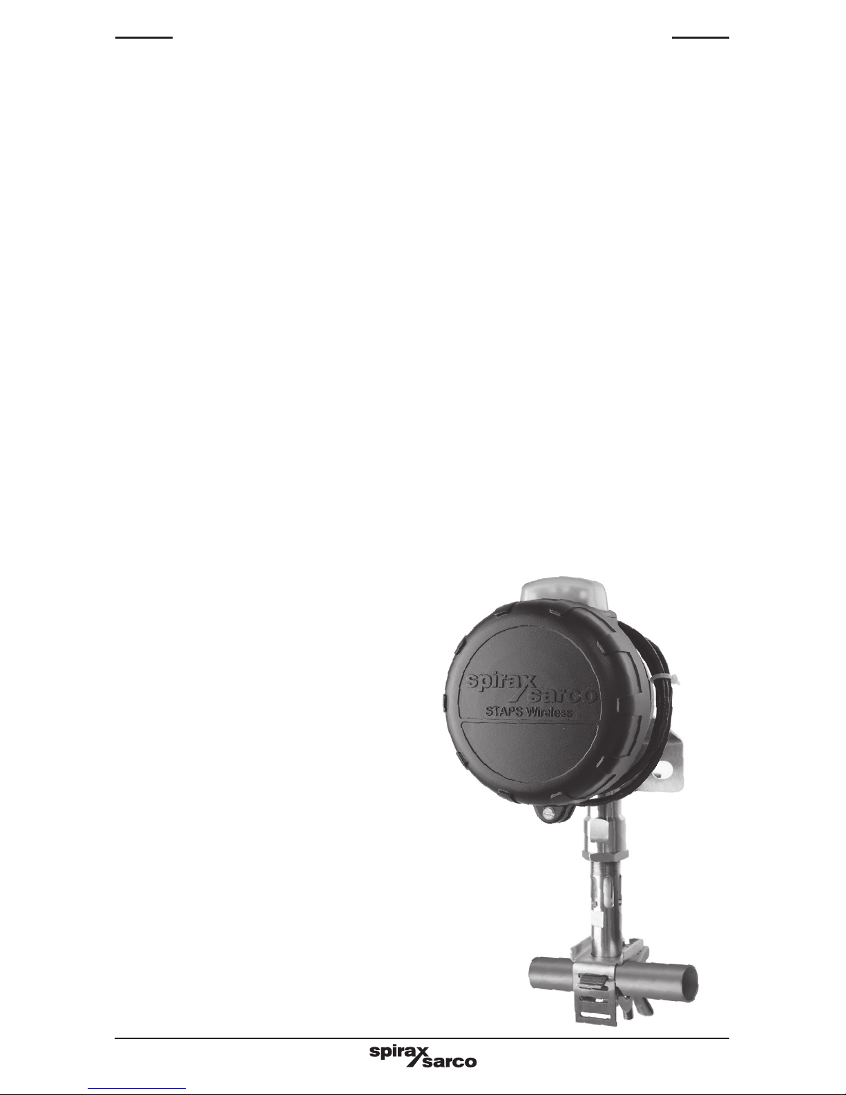
Fig. 1
2. General product information
2.1 General description
The STAPS wireless steam trap monitoring system has been designed to efficiently monitor
and evaluate steam trap operation. It surveys the operation of the steam trap at regular
intervals and identifies poor performance that can cause reduced plant efficiency and
increased energy consumption. It can diagnose both failed-open steam traps that leak
live steam, and those that have failed-closed or are blocked, resulting in waterlogging,
leading to plant damage, product spoilage and health and safety concerns.
Using non-intrusive installation technology combined with a 2.4 GHz wireless network,
it is an ideal solution for steam trap monitoring. It is suitable for use with all types of steam
trap and can be connected to pipework up to 100 mm (4"), via an adjustable clamp.
How does it work?
A head unit assembly mounted on the pipe upstream of the trap to be monitored 'listens'
to the sound signature of the trap in operation. This sound signature is categorised and
transmitted via 2.4 GHz wireless network to a central PC. The PC determines the trap
condition and calculates any steam loss - See software IMI for commissioning the unit into
operation.
Each STAPS head unit assembly is powered by a long life Lithium battery (typical
battery life of over 3 years). It can communicate directly to a receiver that is connected
to the PC software via a LAN connection or via another intelligent head or repeater. The
PC software can be installed onto a PC on the sites internal network, or onto a standalone local PC. The STAPS head, repeater and receiver create a network and can
communicate with each other, passing on the steam trap data to the supervisory PC.
2.2 STAPs head unit assembly
The STAPs head unit includes the head
unit and the sensor and clamp that must be
connected to the steam pipe upstream of the
steam trap that it is monitoring. The head
itself is supplied clamped to the sensor and
connected via 1 m of cable.
The pipe clamp is available in four sizes to
suit the following sized pipelines:
1 - ½" - 1¼"
2 - 1½"
3 - 2" - 2½" and
4 - 3" to 4".
There is also an option with a unique clamp to
secure the head unit to a Spirax Sarco STS17
or STS17.2 pipeline steam trapping station.
The head can be unclamped from the sensor
and refitted remotely (up to 1 m) - See Section
3 for full instructions.
The battery powered head uses a 2.4 GHz
radio to communicate to the receiver.
A head unit can also be configured to act as
a repeater (intelligent head).
Page 6

IM-P014-16 MI Issue 2
6
3.1 Accompanying documents
The following Installation and Maintenance Instructions are required to complete the
system installation:
IM-P014-16 STAPS Wireless Head Unit Quick Installation Guide
IM-P014-25 STAPS Wireless Receiver / Repeater Installation Guide
IM-P014-26 STAPS Wireless Steam Trap Monitoring System Installation and Operating
Instructions for use with Windows 7 operating systems
Or
IM-P014-24 STAPS Wireless Steam Trap Monitoring System Installation and Operating
Instructions for use with Windows XP operating systems
To ensure that the STAPS system operates correctly adhere to Section 3.2 and
you must follow the sequence of installation specified in Section 3.3
3.2 Before Installation:
A preliminary site survey of the plant must be conducted by trained personnel, the survey
will identify the optimum number of Receivers and Repeaters together with their most
effective location, to give the most robust wireless network.
Ensure a discussion has taken place with your Network Administrator, showing them
Section 4.1 of IM-P014-26 or IM-P014-24.
Observe the 'Safety Information' in each of the above documents.
3. Order of installation
Page 7

IM-P014-16 MI Issue 2
7
3.3 Recommended order of installation:
1. Install the application software onto the supporting PC, refer to Section 4.2 of
IM-P014-26 or IM-P014-24.
2. From the results of the site survey, carefully select the optimum position for the
Receiver ensuring that there is a direct line of sight (20 - 30 m) with as many steam traps
that are to be monitored as possible, referring to IM-P014-25.
3. Plug in the Receiver into the network point using an RJ45 cable plug.
4. Plug in the Receiver to the mains power supply, and proceed to switch it on.
5. After a short delay the Receiver symbol will appear in the network maintenance
window on the PC application software, refer to Section 5.3 - Network Maintenance
of IM-P014-26 or IM-P014-24.
If the Receiver is installed on a different sub-net to the PC, refer to Section 5.13 of
IM-P014-26 or IM-P014-24.
If during the site survey it was identified that Repeaters are required complete
Steps 6 to 9, if no Repeaters are required skip to Step 10.
6. Carefully select the optimum site for the Repeater ensuring that there is a direct line
of sight (20 - 30 m) with as many steam traps that are to be monitored as possible,
referring to IM-P014-25.
7. Plug in the Repeater to the mains power supply, and proceed to switch it on (do not plug
a cable into the network connection).
8. After a short delay the Repeater symbol will appear in the network maintenance
window on the PC application software, refer to Section 5.3 - Network Maintenance
of IM-P014-26 or IM-P014-24.
9. Repeat Steps 6 to 8 if further Repeaters were recommended or required.
10. Fit a battery to the first Head, refer to IM-P014-16. As soon as the battery is connected
into the Head it will start to transmit and will communicate with the Receiver or Repeater.
This will show up on the PC software, after 15 to 30 minutes.
Please note:
If a Head is powered up without a Receiver being powered up first, the Head battery
will discharge quickly as the Head is trying to associate itself with a network.
11. Install the Head unit to the upstream side of the assigned trap (within 150 mm).
12. Using the software, assign a trap to the Head, refer to Section 5.6 - Assigning traps to
Heads IM-P014-26 or IM-P014-24.
13. Repeat Steps 6 to 8 for other STAPS Heads until all traps to be monitored within signal
range are completed.
It is recommended to connect all of the Heads in each area of the network associated
to a single Repeater or Receiver identified in the site survey.
14. When all the Heads and Repeaters under a Receiver are installed and reporting correctly,
it is recommended that a unique PAN ID is set for that section of the network before
continuing with other Receiver sections.
Refer to Section 5.8 of IM-P014-26 or IM-P014-24.
For full instructions on each step see individual sections.
Page 8
IM-P014-16 MI Issue 2
8
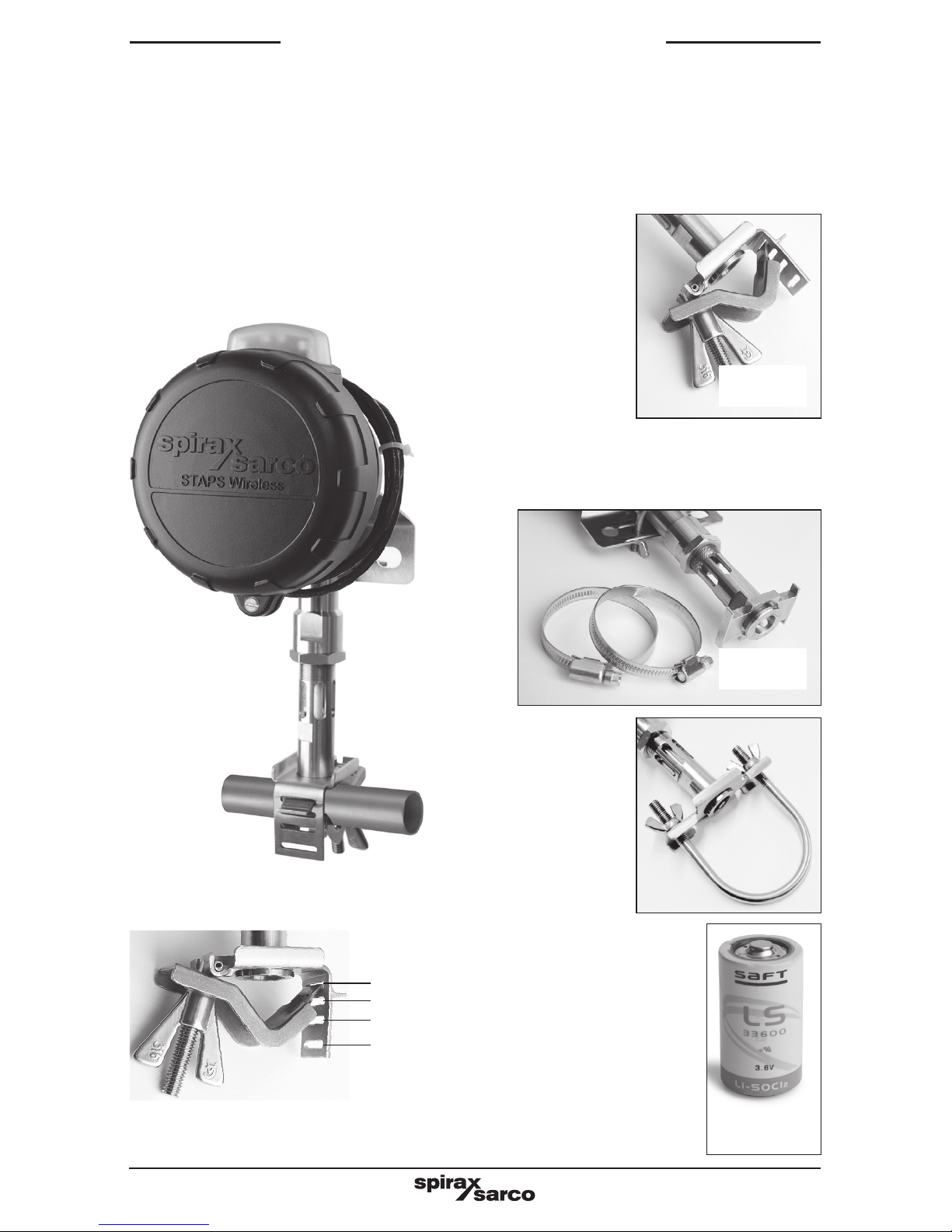
- 1 off SAFT LS33600 3.6V
4. Installation of the
head unit assembly
Note: Before actioning any installation observe the 'Safety information' in Section 1.
The STAPS sensor includes the following parts:
- 1 off head and sensor assembly,
including the head unit and
sensor with top clamp, 'U' bolts
and wing nuts, attached with
1 m of cable.
- 1 off lower
clamp with 'T'
bolt and wing
nut.
Size ½" – 1¼"
Larger sizes use a top clamp with jubilee
clips.
Size 1½", 2"- 2½" and 3"- 4"
Fig. 2
Fig. 3
Fig. 4
Fig. 6
½"
¾"
1"
1¼"
Slot used for size of pipe:
Clamp for use with
a Spirax Sarco
STS17 or STS17.2
compact pipeline
steam trapping
station.
Fig. 5
Page 9
IM-P014-16 MI Issue 2
9
Consider where the STAPS head unit is to be fitted:
- The weather - The head unit is IP65 rated.
- Wireless signal objections - Will adjacent buildings, pipework or other objects obstruct
the wireless signal from reaching the nearest repeater / receiver?
- Interference - Is there any electrical or radio interference that may affect the performance
of the STAPS head unit.
- Access - Is there sufficient access to the head to change the batteries for maintenance?
- Installation - Is there sufficient room at the sensor for the head to be mounted on the
sensor or locally within 1 m?
- Lagging - Ensure that any pipe lagging in the area where the STAPS head is to be fitted
is removed before fitting. DO NOT re-lag the STAPS head unit, including the clamp
and stem.
4.1 Fitting the battery to the sensor head
The head unit assembly is supplied with a SAFT LS 33600 3.6 V battery loose in the box.
Note: It is highly recommended on initial installation that the battery is fitted whilst
the head unit is on a workbench, before it is installed on site.
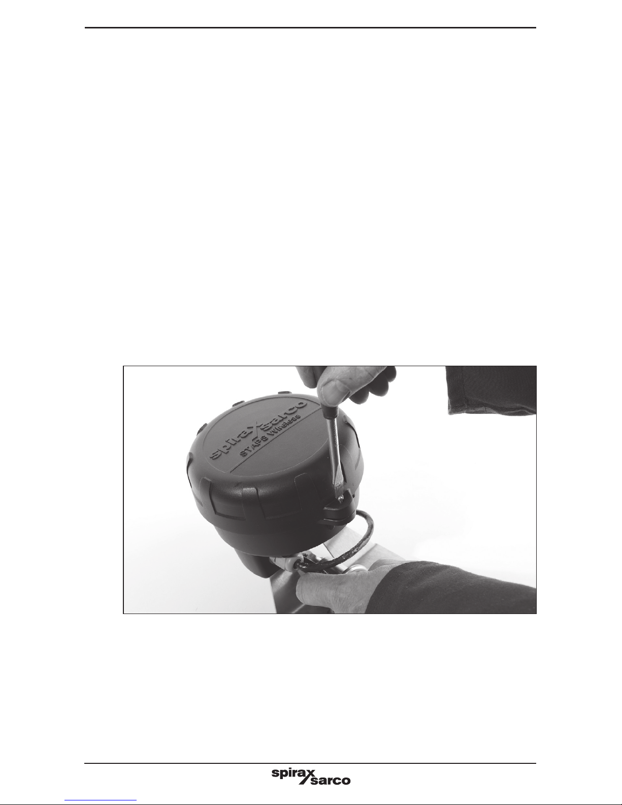
4.1.2 Unscrew the head cover retaining screw.
Fig. 7
Page 10
IM-P014-16 MI Issue 2
10
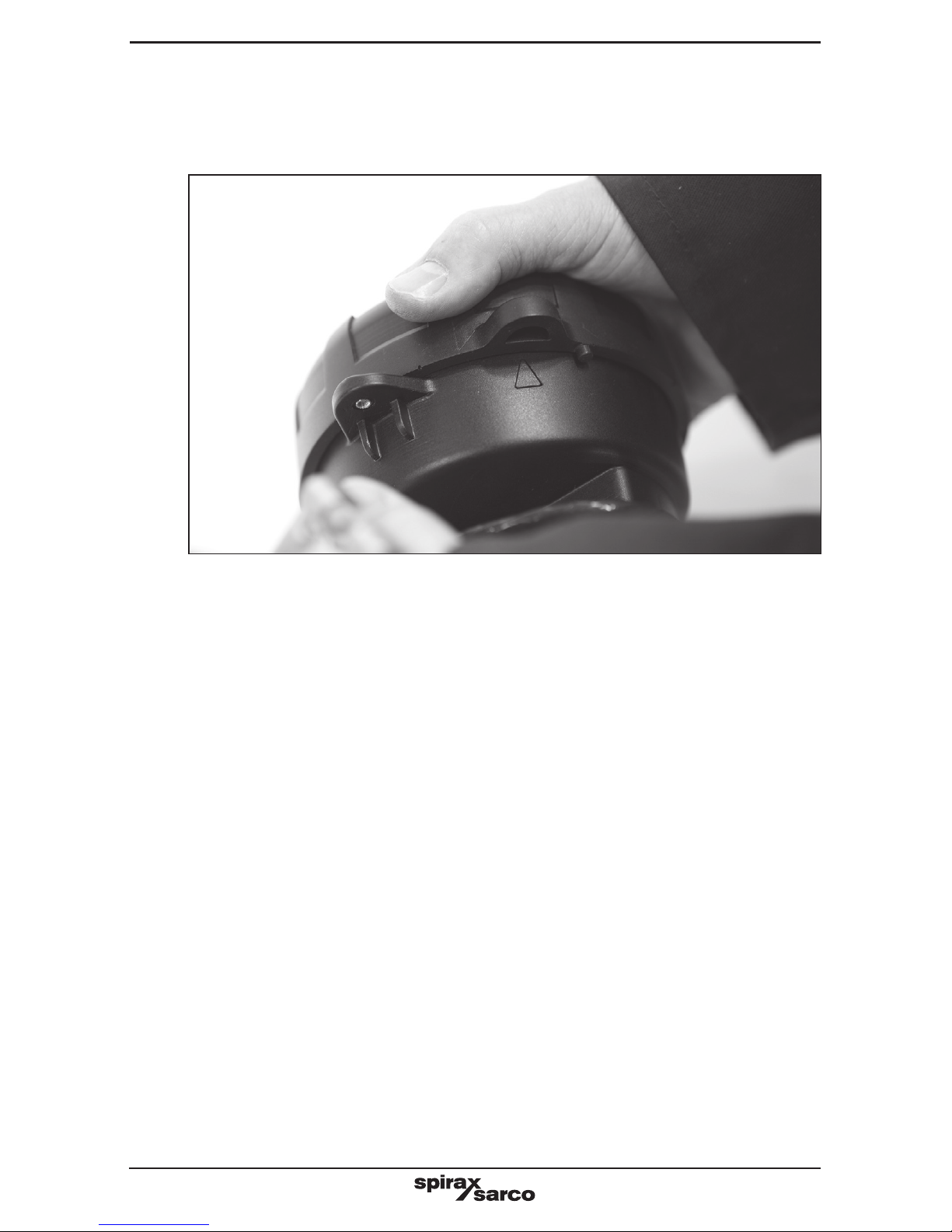
4.1.3 Turn head cover anticlockwise and align the cover lug with the arrow on the body
and pull the cover away from the body.
Fig. 8
Page 11
IM-P014-16 MI Issue 2
11
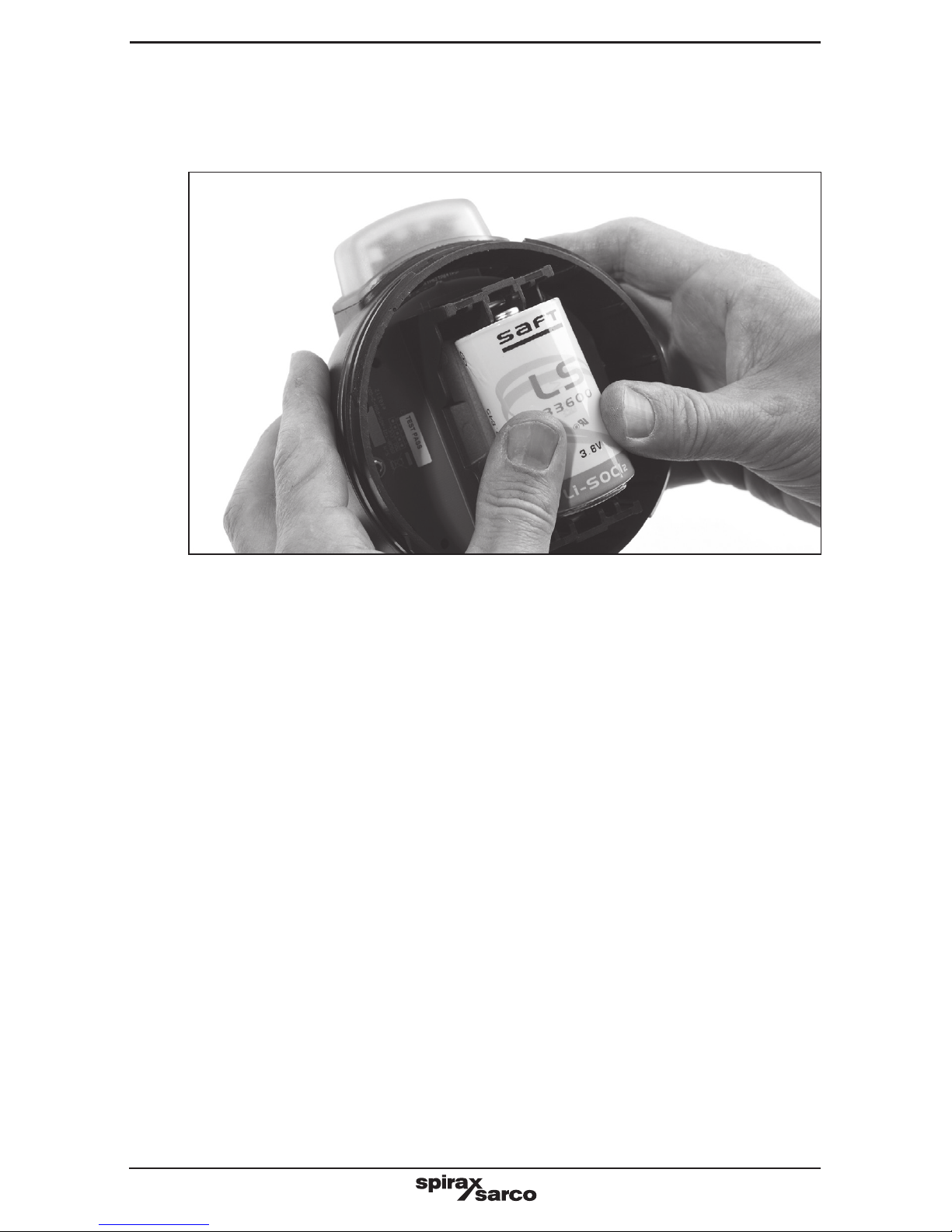
4.1.4 Remove the packaging from the battery and push it into the holder in the head unit.
Ensure that the battery is in the correct orientation as per the orientation marker
(+ to top). Note: Only use a SAFT LS 33600 Lithium Thionyl Chloride 3.6 V battery.
4.1.5 Refit the cover and retaining screw. Check that the 'O' ring seal is in good condition
before refitting the cover, and is correctly seated in place.
Fig. 9
Page 12
IM-P014-16 MI Issue 2
12
4.2 Mounting the head unit
Ensure that any pipe lagging is removed from the area where the STAPS head is
to be fitted. DO NOT re-lag the STAPS Head.
4.2.1 For pipe sizes ½" to 1¼"
Slide the tongue of the lower clamp into the appropriate slot of the top clamp.
Offer the head unit to the pipe within as
close as possible but within 150 mm
upstream of the steam trap to be
monitored.
Hook the 'T' bolt over the top clamp and
tighten the wing nut. Ensure that the head
unit is fitted uppermost (on top of the
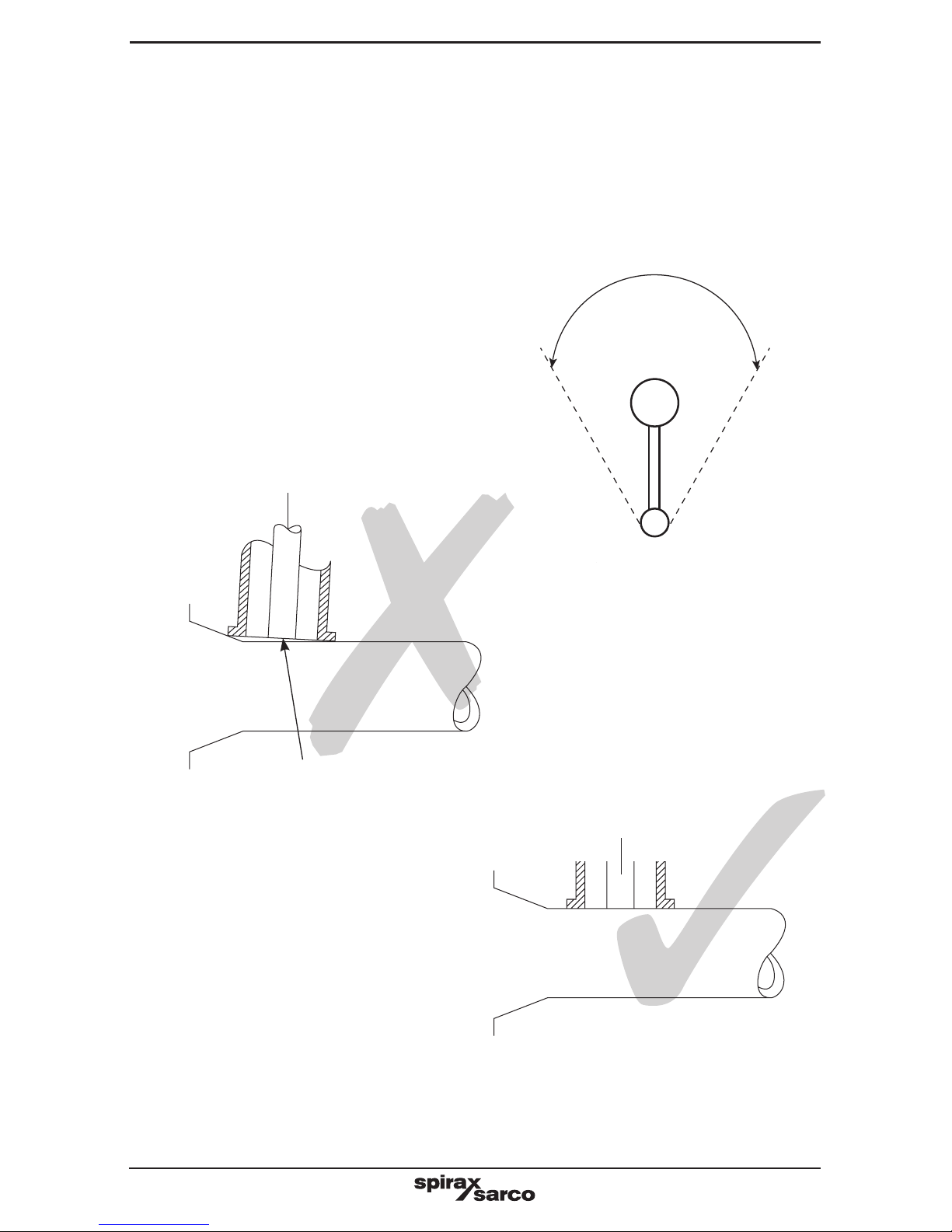
pipe), no greater than a 45° angle.
45°
Head
Pipe
Fig. 10
There will be reduced functionality
if the sensor probe is not fully
compressed to the pipe
Fig. 11
Sensor probe
Ensure that the sensor probe
is fully compressed to the pipe
Fig. 12
Sensor probe
Page 13
IM-P014-16 MI Issue 2
13
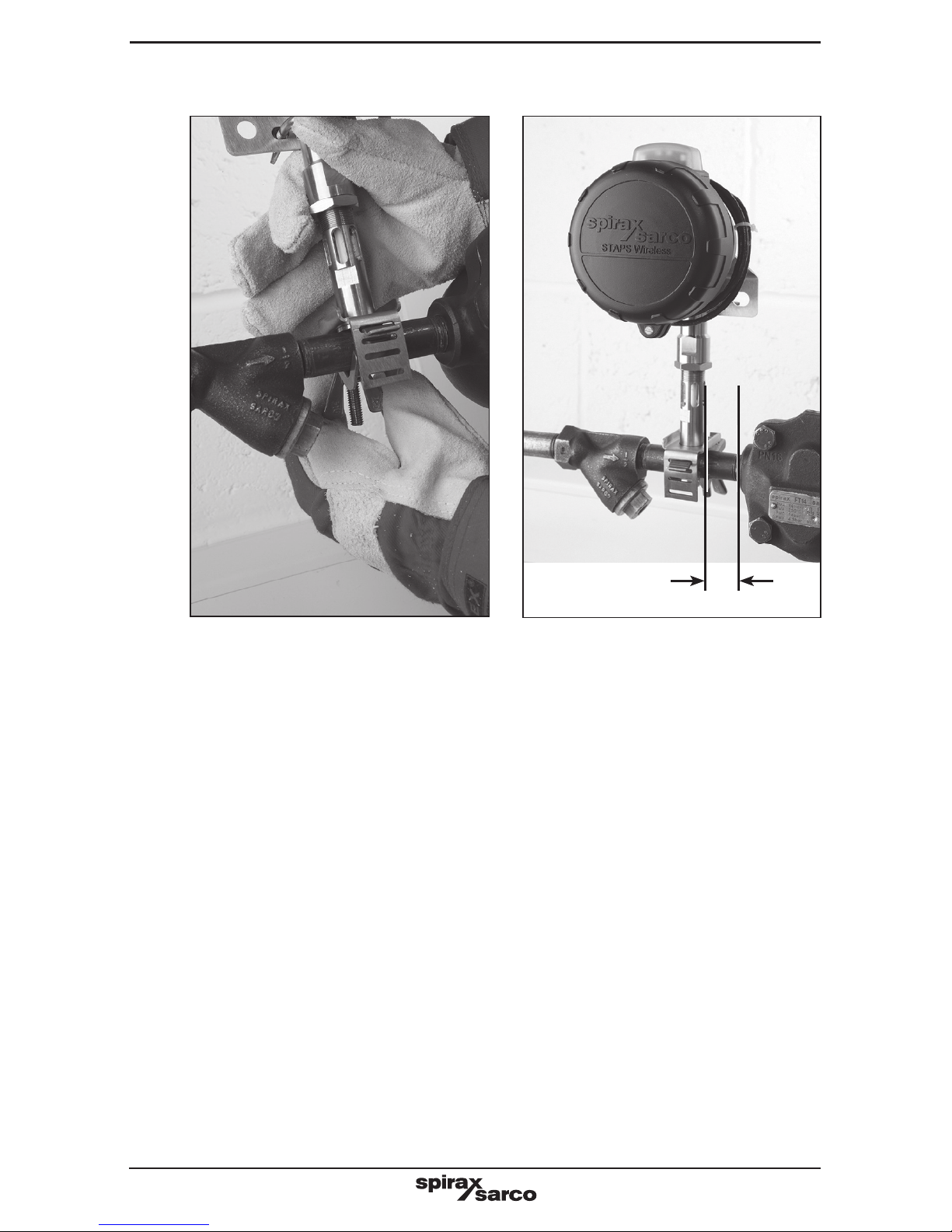
Fig. 13 Fig. 14
Caution: If fitted to a hot pipe, recheck that the clamp is tight after 15 minutes.
Maximum
150 mm
Page 14
IM-P014-16 MI Issue 2
14
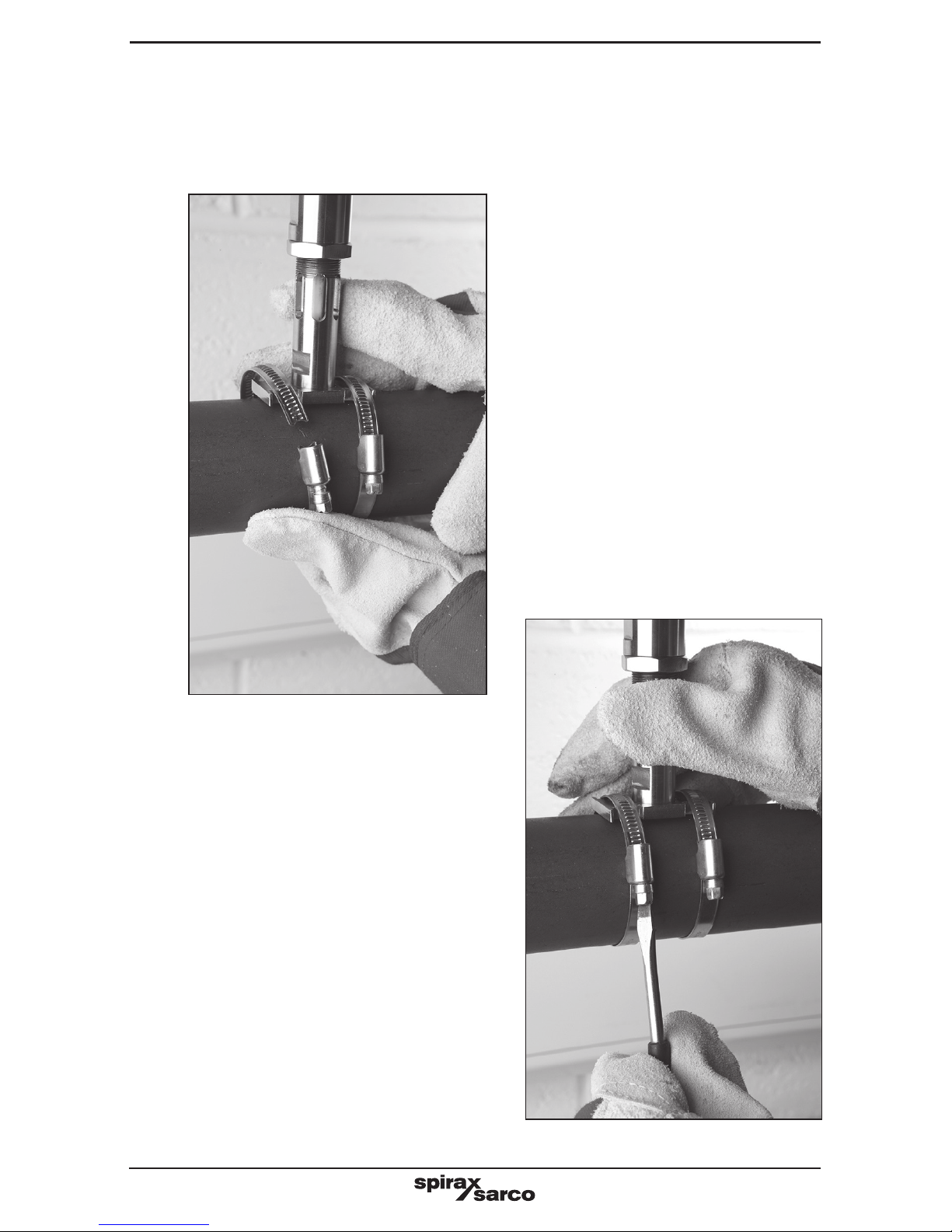
4.2.2 For pipe sizes 1½", 2" - 2½" and 3" - 4"
The larger sizes use jubilee clips rather than a clamp to attach the head unit to the pipe.
Separate the jubilee clips and slide over the pipe and loosely tighten the clip to the
pipe, allowing room to push the top clamp under.
Ensure that the head unit is fitted
uppermost (on top of the pipe), no
greater than a 45º angle. Tighten clips
into position.
Fig. 15
Fig. 16
Caution: If fitted to a hot pipe, recheck
that the clamp is tight after 15 minutes.
Page 15
IM-P014-16 MI Issue 2
15
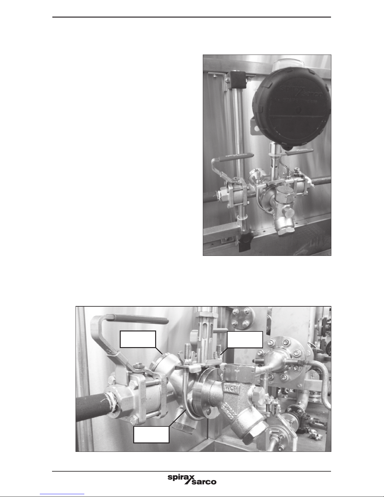
4.2.3 Fitting the STAPS head to the STS17 or STS17.2
Secure the top clamp to the 'U' bolt by tightening the wing nuts.
Fig. 17
Fig. 18
Separate the 'U' bolt from the top
clamp. Slide the 'U' bolt around the
Universal Flange on the STS17.2
casting and place the top clamp such
that the STAPS sensor is upright and
in contact with the top of the universal
flange.
Wing nut
'U' Bolt
STS17.2
Page 16
IM-P014-16 MI Issue 2
16
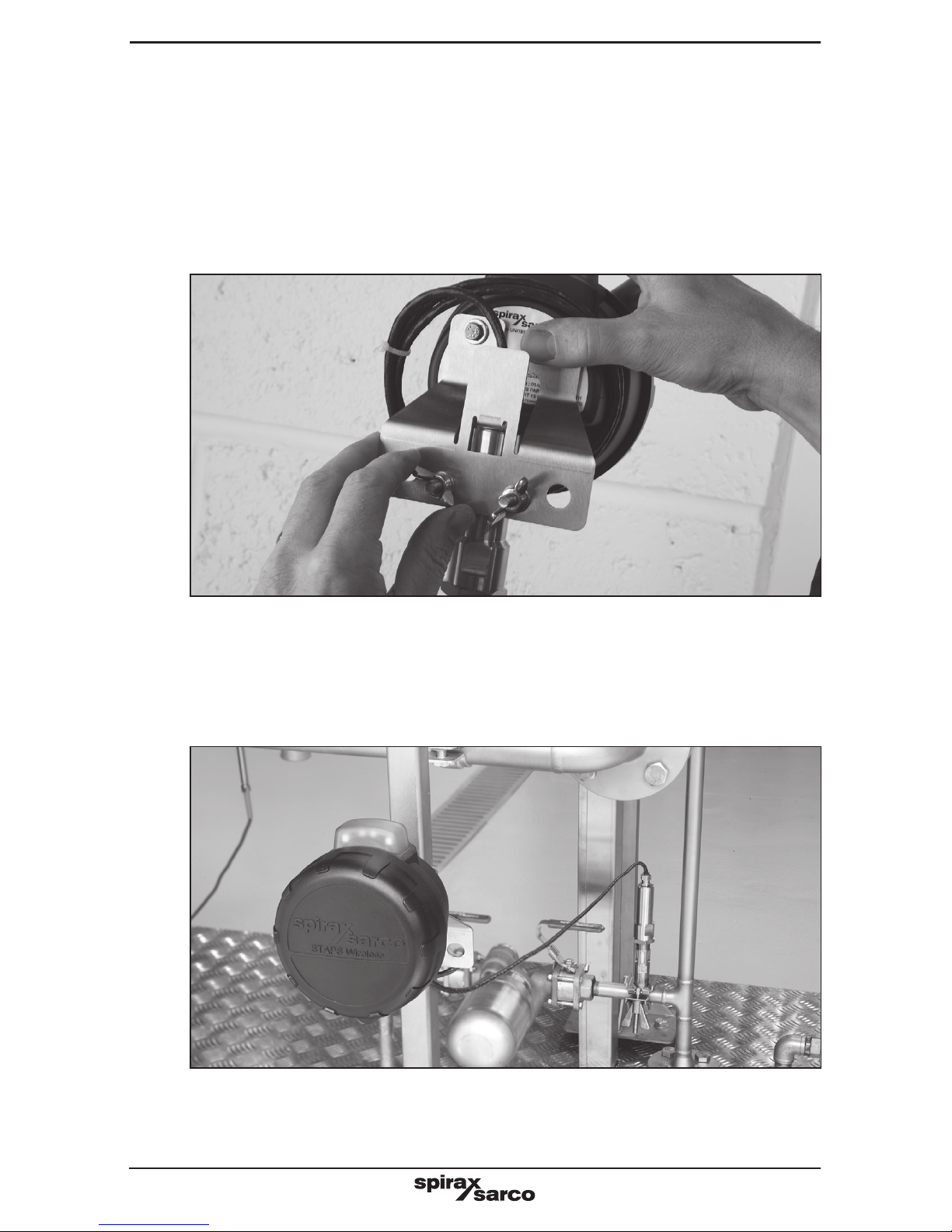
4.3 Fitting the head remote from the sensor
In some circumstances it may be necessary to mount the head away from the sensor.
This may be for temperature (head limited to an ambient temperature of 70ºC),
signal or space restrictions.
4.3.1 There are two options available for remote mounting. The standard head unit comes
with 1 m of cable between the sensor and the head itself. The head is secured to the
sensor with a 'U' bolt and two wing nuts.
By undoing the wing nuts, the head can be removed from the sensor and re-clamped /
attached to another structure in a more convenient place, up to 1 m away. If the
'U' bolt is not suitable, the head can be secured using zip ties (not supplied).
Fig. 19
Fig. 20
Do not attach the head directly to the steam pipe or any other hot structure.
Do not lag the STAPS head unit, including the clamp and stem.
Page 17
IM-P014-16 MI Issue 2
17
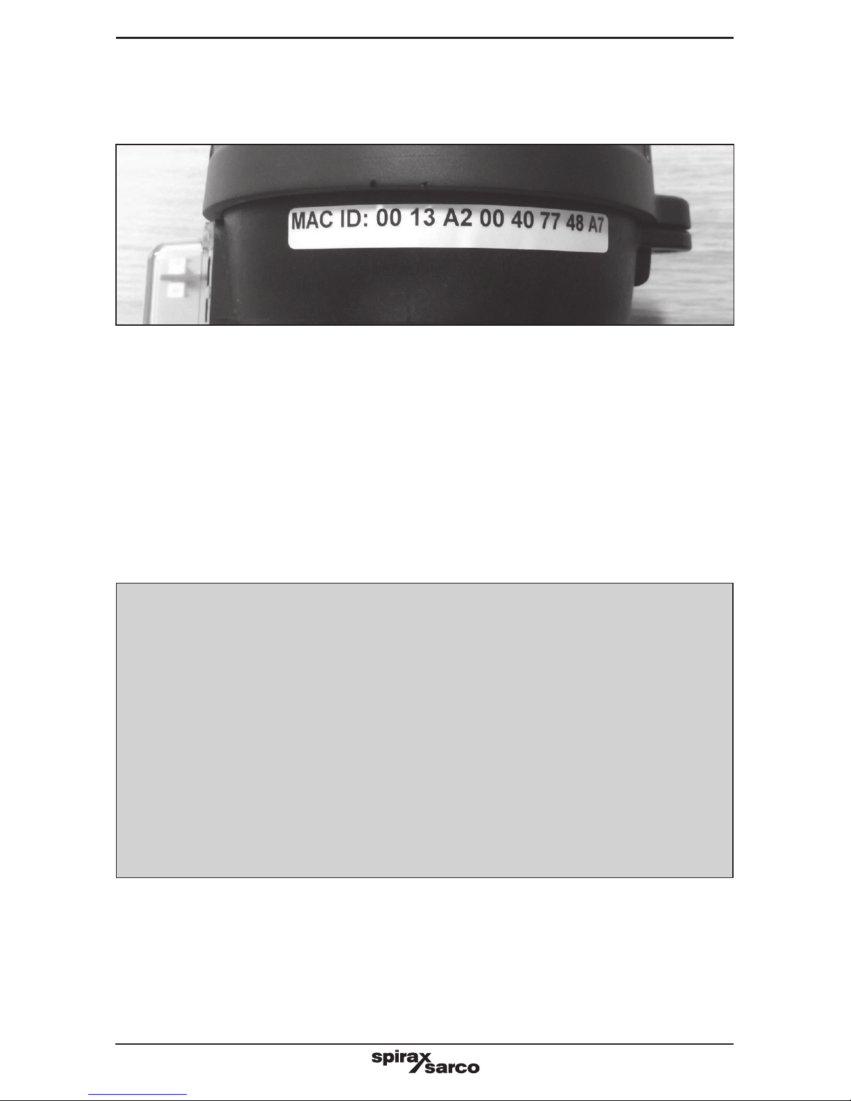
4.4 MAC address and PAN-ID
The MAC address is a unique number to the piece of equipment it is attached to. This cannot
be changed and will remain with the product for its lifetime.
Important: Make sure that MAC ID is noted against a trap type and reference location.
This data will be required for entry into the STAPS software - See Software copyright
statement below.
Information required:
1. Location reference / trap tag No.
2. Type of trap.
3. Size of trap orifice.
4. Steam line pressure at the trap / head is fitted to.
Fig. 21
Software copyright
Certain computer programs contained in this product [or device] were developed
by Spirax-Sarco Limited ('the Work(s)').
Copyright © Spirax-Sarco Limited 2015
All Rights Reserved
Spirax-Sarco Limited grants the legal user of this product (or device) the right
to use the Work(s) solely within the scope of the legitimate operation of the
product (or device). No other right is granted under this licence. In particular
and without prejudice to the generality of the foregoing, the Work(s) may not
be used, sold, licensed, transferred, copied or reproduced in whole or in part
or in any manner or form other than as expressly granted here without the prior
written consent of Spirax-Sarco Limited.
Page 18
IM-P014-16 MI Issue 2
18
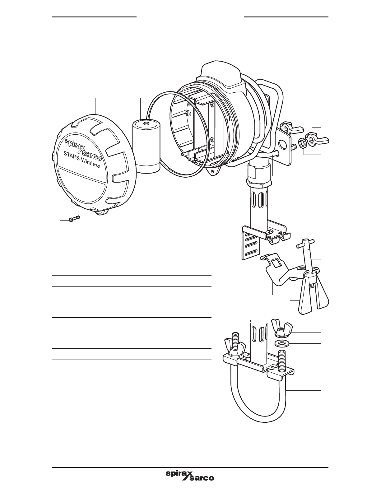
5. Spare parts
Only the parts listed below are available for the STAPS system. No other parts are supplied
as spares.
How to order spares
Always order spare parts by using the description
given in the column headed 'Available spares' and
state the size and unit nomenclature that they are
intended for.
Example:
1 off Battery spares kit (SAFT LS 33600 3.6 V battery) for a STAPS wireless steam trap
monitoring system.
or
1 off Clamp for use with an STS17.2 pipeline trapping station.
Available spares
Battery (SAFT LS 33600 3.6 V battery) 1
'O' ring spares kit 2
Head mounting bracket,
'U' bolt and wing nuts
8, 9, 10 and 19
Clamp
'T' bolt and wing nut 5, 6 and 7
'U' bolt and wing nuts
for an STS17 or STS17.2
20, 21 and 22
Front cover spares kit 3 and 4
3 1
5 6
8
10
9
4 2
19
7
Fig. 22
22
21
20
Page 19

IM-P014-16 MI Issue 2
19
7. Technical data
Head unit: See Section 3 for mounting options.
Integral battery Lithium Thionyl Chloride
Maximum altitude 3 000 m (0.7 bar atmospheric)
Ambient temperature range
-29 to +70°C
Maximum pipe temperature 425°C
Maximum relative humidity 95% Enclosure rating IP66
Output IEE 802-15 2.4 GHz
Visual indicators LED
6. Certification and approvals
United States - Standards used for Certification:
FM3600, FM3610, FM3810, ASME / ISA 60079-0 and ASME / ISA 60079-11
Canada Standards used for Certification:
CSA 1010.1, CSA C22.2 No.157, CSA C22.2 No.25,
CAN / CSAE 60079-0 and CAN / CSA 60079-11
Note:
The above approvals are only valid if the product is installed using the genuine supplied
component parts and accessories, including consumable items such as batteries and power
leads.
Page 20

IM-P014-16 MI Issue 2
20
Head
An individual trap sensing device which is networkable.
Intelligent Head
A normal head unit which has received additional configuration in order for it to act as a repeater
device. The head will wake up and perform the normal trap analysis functions and then it will
arbitrate to offer a re-transmission service for any other heads which are on the network but
not directly in range of a receiver or repeater.
LAN - Local Area Network
A Local Area Network is a logical group of interconnected devices in a limited geographical
area such as a home, school, factory, or office building.
MAC Address - Media Access Control
A media access control address is a unique number (in the form of six groups of two hexadecimal
digits) that is assigned to a networkable device at the time of manufacture. As the number is
unique it can be used to identify and address particular members of a network.
Network Administrator / IT Administrator (IT Admin)
The network administrator is an individual that is responsible for the maintenance and
monitoring of computer hardware, software systems and related equipment that make up a
computer network. This individual should be able to supply the required advise and details to
install the STAPS system onto your companies network.
Orifice Size
The orifice size is the size of the hole in the trap seat that the condensate passes through.
PAN – Personal Area Network
A collection of co-operative devices sharing a similar geographical location and having a
common PAN-ID.
PAN-ID - Personal area network identification
A PAN-ID is a number allocated to a network co-ordinator (receiver). Heads will base a decision
on which network to join based on their PAN-ID. The default PAN-ID is zero which means that the
device will join any network and then assume the PAN-ID of that network. A device with a nonzero PAN-ID allocated by the user will only join a network that has the same non-zero PAN-ID.
Receiver
A receiver is a physical device that creates and manages a PAN. It also functions as a gateway
between the PAN and the Ethernet network.
Repeater
A repeater is a physical device not attached to the Ethernet network but forming part of a
PAN. The function of the repeater is to extend the range of the network, where mains power
is available.
RJ45 - Registered Jack 45
RJ45 plugs and sockets along with cat5e cable are used to connect devices together to
form a network. Sometimes called an 8P8C connector. Commonly used on standard LAN
interconnections
STAPS
Spirax Total Acoustic Performance Solutions.
8. Technical glossary
 Loading...