

Spirax Sarco PN 4000, PN 3400, PN 3500, PN 3600, PN 4200 Installation And Maintenance Instructions Manual
...
3.561.5275.201
IM-P357-12
Issue 3.1 - 2013
© Copyright 2006
EXPERTISE SOLUTIONS SUSTAINABILITY
1. Safety Information
2. General
3. Installation
4. Commissioning
5. Maintenance
6. Spare Parts
Types PN 3000 and PN 4000 Series
Pneumatic Actuators
Installation and Maintenance Instructions

ATTENZIONE
Lavorare in sicurezza con apparecchiature
in ghisa e vapore
Working safely with cast iron products on steam
Informazioni di sicurezza supplementari - Additional Informations for safety
Lavorare in sicurezza con prodotti
in ghisa per linee vapore
I prodotti di ghisa sono comunemente presenti
in molti sistemi a vapore.
Se installati correttamente, in accordo alle
migliori pratiche ingegneristiche, sono dispositivi
totalmente sicuri.
Tuttavia la ghisa, a causa delle sue proprietà
meccaniche, è meno malleabile di altri materiali
come la ghisa sferoidale o l’acciaio al carbonio.
Di seguito sono indicate le migliori pratiche
ingegneristiche necessarie per evitare i colpi
d'ariete e garantire condizioni di lavoro sicure
sui sistemi a vapore.
Movimentazione in sicurezza
La ghisa è un materiale fragile: in caso di
caduta accidentale il prodotto in ghisa non è
più utilizzabile. Per informazioni più dettagliate
consultare il manuale d'istruzioni del prodotto.
Rimuovere la targhetta prima di effettuare la
messa in servizio.
Working safely with cast iron
products on steam
Cast iron products are commonly found on steam
and condensate systems.
If installed correctly using good steam
engineering practices, it is perfectly safe.
However, because of its mechanical properties,
it is less forgiving compared to other materials
such as SG iron or carbon steel.
The following are the good engineering practices required to prevent waterhammer and
ensure safe working conditions on a steam
system.
Safe Handling
Cast Iron is a brittle material. If the product is dropped
during installation and there is any risk of damage
the product should not be used unless it is fully
inspected and pressure tested by the manufacturer.
Please remove label before commissioning

Vapore
Steam
Flusso
Flow
Esempi di esecuzioni corrette ( ) ed errate ( ) sulle linee vapore:
Steam Mains - Do's and Dont's:
Flusso
Flow
Prevenzione dai colpi d’ariete - Prevention of water hammer
Scarico condensa nelle linee vapore - Steam trapping on steam mains:
Intervalli di 30÷50 m. intervals
Pendenza -
Gradient
1:100
Vapore
Steam
Gruppo di scarico
Trap set
Condensa - Condasate
Pendenza -
Gradient
1:100
Gruppo di scarico
Trap set
Gruppo di scarico
Trap set
Condensa - Condasate
Condensa - Condasate
Vapore
Steam

Prevenzione delle sollecitazioni di trazione
Prevention of tensile stressing
Evitare il disallineamento delle tubazioni - Pipe misalignment:
Installazione dei prodotti o loro rimontaggio post-manutenzione:
Installing products or re-assembling after maintenance:
Evitare l’eccessivo serraggio.
Utilizzare le coppie di serraggio
raccomandate.
Do not over tighten.
Use correct torque gures.
Per garantire l’uniformità del carico e dell'allineamento,
i bulloni delle ange devono essere serrati in modo
graduale e in sequenza, come indicato in gura.
Flange bolts should be gradually tightened across
diameters to ensure even load and alignment.

Dilatazioni termiche - Thermal expansion:
Gli esempi mostrano l’uso corretto dei compensatori di dilatzione. Si consiglia di richiedere una
consulenza specialistica ai tecnici dell’azienda che produce i compensatori di dilatazione.
Examples showing the use of expansion bellows. It is highly recommended that expert advise is
sought from the bellows manufacturer.
Guide
Guides
Distanza breve
Short distance
Punto di ssaggio
Fixing point
Movimento assiale
Axial movement
Distanza
media
Medium
distance
Tiranti limitatori
Limit rods
Piccolo
movimento
laterale
Small
lateral
movement
Piccolo
movimento
laterale
Small
lateral
movement
Ampio
movimento
laterale
Large
lateral
movement
Ampio
movimento
laterale
Large
lateral
movement
Guide
Guides
Guide
Guides
Guide
Guides
Punto di ssaggio
Fixing point
Tiranti limitatori
Limit rods
Movimento assiale
Axial movement

3.561.5275.201
2
1.1 Intended use
Referring to the Installation and Maintenance Instructions, name-plate and Technical
Information Sheet, check that the product is suitable for the intended use/application. The
products listed below comply with the requirements of the European Pressure Equipment
Directive 97/23/EC. The products fall within the following Pressure Equipment Directive
categories:
1. Safety Information
* SEP= not subjected to CE marking as per paragraph 3.3 of Directive 97/23/EC.
i) The products have been specifically designed for use on compressed air or condensate
which are in Group 2 of the above mentioned Pressure Equipment Directive. The products’
use on other gas within Group 2 may be possible but, if this is contemplated, Spirax Sarco
should be contacted to confirm the suitability of the product for the application being
considered.
ii) Check material suitability, pressure and temperature and their maximum and minimum
values. If the maximum operating limits of the product are lower than those of the system in
which it is being fitted, or if malfunction of the product could result in a dangerous overpressure
or overtemperature occurrence, ensure a safety device is included in the system to prevent
such over-limit situations.
iii) Determine the correct installation situation and direction of fluid flow.
iv) Spirax Sarco products are not intended to withstand external stresses that may be induced
by any system to which they are fitted. It is the responsibility of the installer to consider these
stresses and take adequate precautions to minimise them.
v) Remove protection covers from all connections before installation.
1.2 Access
Ensure safe access and if necessary a safe working platform (suitably guarded) before attempting
to work on the product. Arrange suitable lifting gear if required.
1.3 Lighting
Ensure adequate lighting, particularly where detailed or intricate work is required.
1.4 Hazardous liquids or gases in the pipeline
Consider what is in the pipeline or what may have been in the pipeline at some
previous time. Consider: flammable materials, substances hazardous to health, extremes of
temperature.
1.5 Hazardous environment around the product
Consider: explosion risk areas, lack of oxygen (e.g. tanks, pits), dangerous gases, extremes
of temperature, hot surfaces, fire hazard (e.g. during welding), excessive noise, moving
machinery.
1.6 The system
Consider the effect on the complete system of the work proposed. Will any proposed action
(e.g. closing isolation valves, electrical isolation) put any other part of the system or any
personnel at risk?
Product: Series PN3000 & PN4000 Group 2 Group 2
Actuators
PS (bar) V (litres)
Gas Liquid
Model PN3200 - PN4200 6.0 0.6 *SEP Model PN3300 - PN4300 (H) 6.0 1.0 *SEP Model PN3400 - PN4400 (H) 4.0 2.1 *SEP Model PN3500 - PN4500 (H) 2.5 3.6 *SEP Model PN3600 - PN4600 (H) 2.5 5.7 *SEP -

3.561.5275.201 3
Dangers might include isolation of vents or protective devices or the rendering ineffective
of controls or alarms. Ensure isolation valves are turned on and off in a gradual way to
avoid system shocks.
1.7 Pressure systems
Ensure that any pressure is isolated and safely vented to atmospheric pressure. Consider
double isolation (double block and bleed) and the locking or labelling of closed valves. Do not
assume that the system has depressurised even when the pressure gauge indicates zero.
1.8 Temperature
Allow time for temperature to normalise after isolation to avoid danger of burns.
1.9 Tools and consumables
Before starting work ensure that you have suitable tools and/or consumables
available. Use only genuine Spirax Sarco replacement parts.
1.10 Protective clothing
Consider whether you and/or others in the vicinity require any protective clothing to protect
against the hazards of, for example, chemicals, high/low temperature, radiation, noise, falling
objects, and dangers to eyes and face.
1.11 Permits to work
All work must be carried out or be supervised by a suitably competent person.
Installation and operating personnel should be trained in the correct use of the
product according to the Installation and Maintenance Instructions.
Where a formal "permit to work" system is in force it must be complied with. Where
there is no such system, it is recommended that a responsible person should know what work
is going on and, where necessary, arrange to have an assistant whose primary responsibility is
safety.
Post "warning notices" if necessary.
1.12 Handling
Manual handling of large and/or heavy products may present a risk of injury. Lifting, pushing,
pulling, carrying or supporting a load by bodily force can cause injury particularly to the back. You
are advised to assess the risks taking into account the task, the individual, the load and the
working environment and use the appropriate handling method depending on the circumstances
of the work being done.
1.13 Residual hazards
In some cases the product is provided with pre-compressed springs.
Any operation to open the spring housing is to be carried on strictly following the correct
procedure given in the Instalaltion and Maintenance Instructions.
1.14 Freezing
Provision must be made to protect products which are not self-draining against frost damage in
environments where they may be exposed to temperatures below freezing point.
1.15 Disposal
Unless otherwise stated in the Installation and Maintenance Instructions, this product is recyclable
and no ecological hazard is anticipated with its disposal providing due care is taken.
1.16 Returning products
Customers and stockists are reminded that under EC Health, Safety and Environment Law,
when returning products to Spirax Sarco they must provide information on any hazards and the
precautions to be taken due to contamination residues or mechanical damage which may
present a health, safety or environmental risk. This information must be provided in writing
including Health and Safety data sheets relating to any substances identified as hazardous or
potentially hazardous.

3.561.5275.201
4
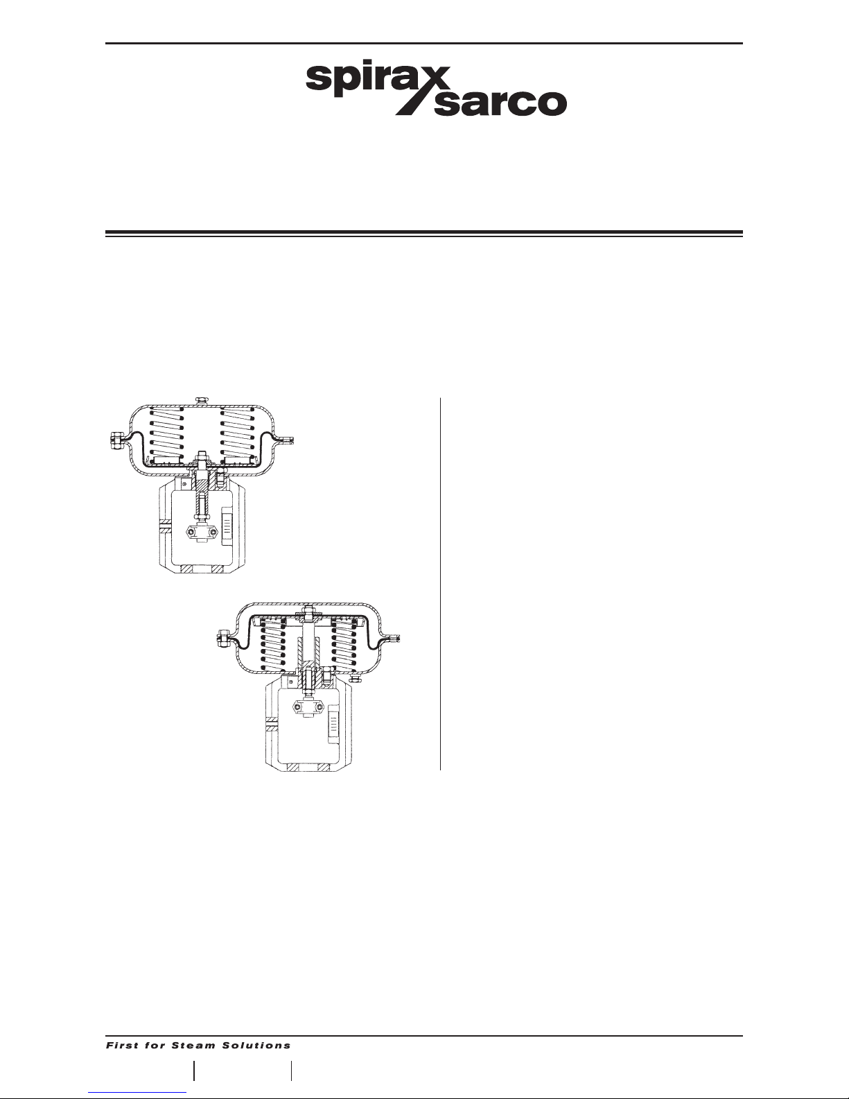
2. General
PN 3000 Series, Spring Extend Pneumatic Actuators
Spring ranges
Actuator Types Spring Range Travel
3220 0.2 (0.4) to 1 (1.2) bar 20mm
3225 0.4 to 2 bar 20mm
3229 1 to 2 bar 20mm (15mm on-off)
3320 0.2 (0.4) to 1 (1.2) bar 20mm
3325 0.4 to 2 bar 20mm
3326 1 to 3 bar 20mm
3339 1 to 2 bar 30mm (20mm on-off)
3420 0.2 (0.4) to 1 (1.2) bar 20mm
3425 0.4 to 2 bar 20mm
3426 1 to 3 bar 20mm
3430 0.2 (0.4) to 1 (1.2) bar 30mm
3435 0.4 to 2 bar 30mm
3436 1 to 3 bar 30mm
3520 0.2 (0.4) to 1 (1.2) bar 20mm
3525 0.4 to 2 bar 20mm
3524 0.8 to 1.5 bar 20mm
3530 0.2 (0.4) to 1 (1.2) bar 30mm
3535 0.4 to 2 bar 30mm
3534 0.8 to 1.5 bar 30mm
3620 0.2 (0.4) to 1 (1.2) bar 20mm
3625 0.4 to 2 bar 20mm
3624 0.8 to 1.5 bar 20mm
3630 0.2 (0.4) to 1 (1.2) bar 30mm
3635 0.4 to 2 bar 30mm
3634 0.8 to 1.5 bar 30mm
Actuator Type Valve Type
20 mm travel LE Series (DN 15 - 50)
30 mm travel LE Series (DN 65 - 100)
Technical Data
Temperature Range -20° to 100°C
Max operating pressure
PN3200/3300 6 bar
PN3400 4 bar
PN3500/3600 2.5 bar
Air Supply Connection
Actuator Type Connection
PN 3200 to 3600 Series ¼" NPT
Compressed Air Consumption
Actuator Type Travel Volume (NLitres)
3200 Series 20 mm 0.6
3300 Series 20 mm 1.0
3400 Series
20 mm 1.4
30 mm 2.1
3500 Series
20 mm 2.4
30 mm 3.6
3600 Series
20 mm 3.8
30 mm 5.7
Description
A range of compact linear actuators having 5 diaphragm sizes for matching the requirements of
different valves at various differential pressures. Each actuator is fitted with a stroke indicator
and incorporates a semi-rolling diaphragm which gives good linearity over the operating
stroke.These actuators are designed to operate with two port LE valves as detailed below.
Available types
Spring extend spindle, multi spring, yoke mounted actuators 3200, 3300, 3400, 3500, and 3600 Series.

3.561.5275.201 5
Materials
No Part Material
1 Diaphragm Housing Pressed Steel
2 Diaphragm Reinforced Nitrile Rubber
3 Diaphragm Plate Pressed Steel
4 Springs Spring Steel
5 Spindle Stainless Steel
6 Lock Nut Stainless Steel
7 Spacer Zinc Plated Steel
8 "O" Ring Rubber
9 Spring Guide Zinc Plated Steel
10 Diaphragm Clamp Zinc Plated Steel
11 Bearing Bronze
12 "V" Ring Rubber
13 Yoke Cast Iron
14 Gasket Non Asbestos Fibre
15 Fixing Screws Steel
16 Housing Bolts & Nuts Steel
17 Top Adaptor Steel
18 Lock Nut Steel
19 Bottom Adaptor Steel
20 Connectors Stainless Steel
21 Connectors Bolts & Nuts Stainless Steel
22 Travel Indicator Aluminum
23 Cap (with vent hole) Plastic
Fig. 1

3.561.5275.201
6
PN 4000 Series, Spring Retract Pneumatic Actuators
Available types
Spring retract spindle, multi spring, yoke mounted actuators 4200, 4300, 4400, 4500, and 4600
Series.
Description
A range of compact linear actuators having 5 diaphragm sizes for matching the requirements of
different valves at various differential pressures. Each actuator is fitted with a stroke indicator
and incorporates a semi-rolling diaphragm which gives good linearity over the operating
stroke.These actuators are designed to operate with two port LE valves as detailed below.
Spring ranges
Actuator Types Spring Range Travel
4220 0.2 to 1 bar 20mm
4320 0.2 to 1 bar 20mm
4420 0.2 to 1 bar 20mm
4430 0.2 to 1 bar 30mm
4520 0.2 to 1 bar 20mm
4530 0.2 to 1 bar 30mm
4620 0.2 to 1 bar 20mm
4630 0.2 to 1 bar 30mm
Actuator Type Valve Type
20 mm travel LE Series (DN 15 - 50)
30 mm travel LE Series (DN 65 - 100)
Technical Data
Temperature Range -20° to 100°C
Max operating pressure
PN4200/4300 6 bar
PN4400 4 bar
PN4500/4600 2.5 bar
Air Supply Connection
Actuator Type Connection
PN 3200 to 3600 Series ¼" NPT
Compressed Air Consumption
Actuator Type Travel Volume (NLitres)
4200 Series 20 mm 0.6
4300 Series 20 mm 1.0
4400 Series
20 mm 1.4
30 mm 2.1
4500 Series
20 mm 2.4
30 mm 3.6
4600 Series
20 mm 3.8
30 mm 5.7

3.561.5275.201 7
Fig. 2
Materials
No Part Material
1 Diaphragm Housing Pressed Steel
2 Diaphragm Reinforced Nitrile Rubber
3 Diaphragm Plate Pressed Steel
4 Springs Spring Steel
5 Spindle Stainless Steel
6 Lock Nut Stainless Steel
7 Spacer Zinc Plated Steel
8 "O" Ring Rubber
9 Spring Guide Zinc Plated Steel
10 Diaphragm Clamp Zinc Plated Steel
11 Bearing Bronze
13 Yoke Cast Iron
14 Gasket Non Asbestos Fibre
15 Fixing Screws Steel
16 Housing Bolts & Nuts Steel
17 Top Adaptor Steel
18 Lock Nut Steel
19 Bottom Adaptor Steel
20 Connectors Stainless Steel
21 Connectors Bolts & Nuts Stainless Steel
22 Travel Indicator Aluminum
23 Cap (with vent hole) Plastic
24 Spacer Plastic

3.561.5275.201
8
See also separate Installation and Maintenance Instructions for the control valves. For details of
differential pressures associated with KE and LE valves refer to Technical Information Sheet TIS
1.312 for PN3000 series actuators and TIS 1.313 for PN4000 series actuators.
The actuators should be installed in such a position as to allow full access to both actuator and
valve for maintenance purposes. The preferred mounting position is with the actuator and valve
spindle in the vertical position above or below the horizontal pipework.
The actuator ambient limits are -20°C to +110°C. For low temperature conditions the air supply
must be dry. For high temperature conditions, insulate the control valve and pipework to protect
the actuator.
Warning
The actuator housing must only be pressurized on the opposite side of the diaphragm to the
springs. The housing vent cap must left be unrestricted.
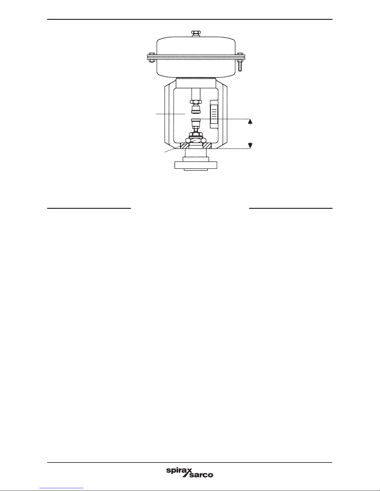
3.1 Fitting Actuator to Valve (Ref. to fig. 1, 2, 3 & 4)
1. Locate valve in support fixture and secure in position. Remove the actuator mounting nut
from the valve.
2. Remove the connector clamp brackets (20) from the actuator spindle by removing the 2
nuts and bolts (21). Remove the valve spindle adaptor (19).
3. Assemble the valve spindle adaptor to the valve spindle ensuring the valve is on its seat.
Adjust the distance between the adaptor top face and the bonnet shoulder to the value
indicated in Fig. 3.
Secure in this position with the spindle locknut.
Do not tighten.
4. Slacken actuator adaptor lock nut (18) & screw adaptor (17) up the actuator spindle as far
as possible.
Do not tighten locknut.
5. Assemble air fitting to actuator housing and locate complete actuator onto the valve assembly.
6. For PN3000 series actuators only.
Apply the maximum air signal pressure (refer to actuator label) to the actuator and assemble
the mounting nut on to valve bonnet.
Tighten to within ~1 full turn of fully tight.
7. For PN3000 series actuators only.
Apply the minimum air signal pressure (refer to actuator label) to the actuator.
8. For PN4000 series actuators only.
Apply the maximum air signal pressure (refer to actuator label), to the actuator.
9. Adjust the top adaptor until it locates with the spindle adaptor.
Do not tighten locknut.
10. Re-assemble the connector clamp brackets with the threaded holes of the bracket at the
same side as the travel indicator plate.
Secure with the 2 nuts and bolts. Torque to 2 nm.
11. Open & close valve 3 times to allow all components to self align (this is why locknuts are left
untightened at this stage).
12. Apply air signal to position valve @ ~ 50% lift position.
13. Tighten both adaptor locknuts. Caution: take care not to turn actuator spindle as this may
cause damage to diaphragm.
14. Tighten mounting nut to secure actuator to valve and torque to 50 nm.
15. This completes the main assembly. However, to check the spindle alignment is perfect,
temporarily remove the connector clamp brackets & inflate the actuator to separate upper
& lower spindle adaptors.
If correctly aligned the connectors will meet each other in perfect alignment. If not, slacken
all tightened nuts & repeat assembly sequence.
Note than some lateral movement between the actuator yoke & the valve bonnet is provided
on more recent PN3000 & PN4000 actuators.
16. Finally, check actuator signal range and stroke at open/closed positions by applying air
signal pressure to the actuator in line with actuator nameplate.
Check for smooth operation and adjust travel indicator on yoke if necessary.
Note: Before mounting the connectors It may be necessary to adjust the position of the actuator
spindle adaptor. Follow the spring adjust procedure as described in Section 4.
3. Installation
3.561.5275.201 9
Fig. 3
A = 71 mm for DN 15 to DN 50 Valves
91 mm for DN 65 to DN 100 Valves
If the actuator/valve has been supplied with a positioner reference should be made to the
separate Installation and Maintenance Instructions for this product.
4.1 Adjusting Spring
The actuator spring range and lift off pressure will be indicated on the nameplate. Should it be
necessary to check or adjust the lift off pressure the procedure is descibed in paragraphs 4.2
and 4.3.
4.2 PN3000 Spring Extend Actuators
Note: Adjustment of the spring will only alter the pressure of the control signal air at which the
valve commences to move off its seat (set point) and will not alter the spring pressure range
require to move the valve through its full travel i.e. 0.2 to 1.0 bar spring (range 0.8 bar) set to
commence to lift at 0.4 bar will require a 1.2 bar air pressure (0.4 + 0.8) to obtain valve full travel.
To adjust set point refer to fig. 2 and proceed as follows:
Ensure the control valve has been isolated and the actuator housing is pressure free.
Loosen and remove connector nuts and screws (21) and remove connectors (20).
Using two spanners whilst holding actuator spindle loosen actuator adaptor lock nut (18).
Apply the control signal pressure required to commence lifting the actuator spindle.
With the valve plug remaining on its seat adjust the actuator spindle adaptor until it presses
tightly against the valve spindle. Finger tighten lock nut (18). See Fig. 4 for correct installation.
Release the control air signal. Fit the connectors across the adaptors (17) and (19). Fit connectors
locking screws and nuts and tighten to 2 Nm.
Recheck that the valve just commences to move off its seat at the right spring range minimum
pressure and is fully open at the spring range maximum pressure. Finally bring the spindle at mid
travel and tighten lock nut (18) to the right torque.
After the test check the position of the travel indicator against the "arrow" of the connector and
adjust its position accordingly.
Important
To prevent damage to the valve seat, please ensure the plug does not turn while pressing on the
seat during assembling or adjustment.
To prevent damage to the diaphragm ensure the actuator spindle is not allowed to
rotate when the diaphragm is assembled within its housing.
4. Commissioning
A
Mid travel
Mounting nut

3.561.5275.201
10
Fig. 4 Assembly of Actuator Adaptor, Valve Adaptor and Connectors
4.3 PN4000 Spring Retract Actuators
Note: Adjustment of the spring will only alter the pressure of the control signal air at which the
valve commences to move off its seat (set point) and will not alter the spring pressure range
require to move the valve through its full travel i.e. 0.2 to 1.0 bar spring (range 0.8 bar) set to
commence to lift at 0.4 bar will require a 1.2 bar air pressure (0.4 + 0.8) to obtain valve full travel.
To adjust set point refer to fig. 2 and proceed as follows:Ensure the control valve has been isolated and the actuator housing is pressure free.
Loosen and remove connectors nuts and screws (21) and remove connectors (20).
Using two spanners whilst holding actuator spindle loosen actuator adaptor lock nut (18).
Apply the control signal pressure required to complete the full travel of the actuator spindle.
With the valve plug remaining on its seat adjust the actuator spindle adaptor until it presses
tightly against the valve spindle. Finger tighten lock nut (18).See Fig. 4 for correct installation.
Fit the connectors across the adaptors (17) and (19). Fit connectors locking screws and nuts
and tighten to 2 Nm.
Release the air control pressure and recheck that the valve just commences to move toward
the seat at the right spring range minimum pressure and is fully closed at the spring range
maximum pressure.
Finally bring the spindle at mid travel and tighten lock nut (18) to the right torque.
After the test check the position of the travel indicator against the "arrow" of the connector and
adjust its position accordingly.
Actuator Spindle
Valve Spindle
Lock Nut (22)
Valve Adaptor (19)
Connectors (20)
Actuator Adaptor (17)
Lock Nut (18)
Connectors Locking
Screws (21)

3.561.5275.201 11
Table 1: PN3000/PN4000 Spring
Actuator Spring Numb. of Ins. Dia. Length Identification
Type Range
Travel
Springs (mm) (mm) (Vert.Stripe)
3220/4220 0.2-1.0 bar 20 mm
1 42 73 Black
1 29 73 Red
3225 0.4-2.0 bar 20 mm
1 42 73 Yellow
1 29 73 Violet
3229 1.0-2.0 bar
20 mm 1 54
84
Black
(15mm on-off) 1 69 Black
3320/4320 0.2-1.0 bar 20 mm 4 42 84 Black
3325 0.4-2.0 bar 20 mm 4 42 84 Yellow
3326 1.0-3.0 bar 20 mm
4 42 84 Yellow
4 29 84 Red
3339 1.0-2.0 bar
30 mm
4 54 84 Black
(20mm on-off)
3420/4420 0.2-1.0 bar 20 mm
2 42 84 Yellow
2 42 84 Black
3425 0.4-2.0 bar 20 mm
5 42 84 Yellow
4 29 84 Red
3426 1.0-3.0 bar 20 mm 5 42 104 White
3430/4430 0.2-1.0 bar 30 mm
2 54,5 107 White
2 36 107 Green
3435 0.4-2.0 bar 30 mm
4 54,5 107 White
4 36 107 Green
3436 1.0-3.0 bar 30 mm
4 54,5 125 White
5 36 125 Green
3520/4520 0.2-1.0 bar 20 mm
6 54,5 107 White
2 36 107 Green
3525 0.4-2.0 bar 20 mm 8 42 104 White
3524 0.8-1.5 bar 20 mm 7 45 125 Brown
3530/4530 0.2-1.0 bar 30 mm
4 54,5 125 White
2 36 125 Green
3535 0.4-2.0 bar 30 mm
6 54,5 125 White
6 36 125 Green
3534 0.8-1.5 bar 30 mm 7 47 135 Blue
3620/4620 0.2-1.0 bar 20 mm
8 54,5 125 White
6 36 125 Green
3625 0.4-2.0 bar 20 mm 12 42 104 White
3624 0.8-1.5 bar 20 mm 8 56 123 Brown
3630/4630 0.2-1.0 bar 30 mm
6 54,5 125 White
2 36 125 Green
3635 0.4-2.0 bar 30 mm
9 54,5 125 White
8 36 125 Green
3634 0.8-1.5 bar 30 mm 8 57 134 Blue

3.561.5275.201
12
The PN3000 and PN4000 series pneumatic actuators are maintenance free. To ensure satisfactory
operation it is strongly recommended that the control signal air is filtered and supplied free of oil and
water. Should it be necessary to replace spare parts the following procedure should be used.
5.1 Removing Actuator from Valve
Drive actuator into approximately mid-travel position with the air supply. Loosen and remove
connectors nuts and screws (21) and remove connectors (20).
Loosen and remove yoke monting nut and lift actuator off the valve.
Reduce air supply pressure until housing is pressure free. Disconnect air supply from the actuator.
5.2 PN3000 Series
5.2.1 Diaphragm Kit - How to Fit
Remove actuator from valve as described in Section 5.1. Loosen and remove housing screws
(16) and remove housing lid (1).
Note 1 - On certain spring ranges 3 off longer hosing bolts are fitted (16). These should be
removed after all other bolts are removed and should be loosened evenly to prevent distortion.
Using two spanners whilst holding actuator spindle (5), loosen plate locknut (6). Remove springs
(4), spacer (7), "O" ring (8), diaphragm plate (3) and diaphragm (2).
Refit new diaphragm and "O" ring reassembling all items in reverse order. Using two spanners,
whilst holding actuator spindle tighten plate lock nut. Refer to Table 1 for torque rating.
Refit top housing and securing nuts and bolts.
2 - While supporting the actuator spindle so that the diaphragm sits evenly in the lower housing,
tighten evenly housing securing bolts to avoid distortion. On some spring ranges 3 off longer
housing bolts are provided to cater for the longer spring. If supplied, these should be psitioned
120° apart and tightened evenly prior to fitting the remaining bolts.
3 - To avoid distortion of the diaphragm do not fully tighten housing bolts until all bolts have been
fitted. Final tightening should then be carried out evenly. Refer to Table 2 for torque rating.
5.2.2 Spring Kit - How to Fit
Remove actuator from valve as described in Section 5.1. Loosen and remove housing screws
(16) and remove housing lid (1) as described in Section 5.2.1. Remove springs.
Replace new springs; While supporting the actuator spindle so that the diaphragm sits evenly in
the lower housing, refit top housing and tighten bolts evenly.
Refer to Section 5.2.1. Note 2 and 3.
5. Maintenance
Table 2: Recommended tightening torques
Actuator
Housing Bolts (16) Lock Nut (6)
Series
Size Torque Nm Size Torque Nm
PN3200/4200 M6 5 +/- 0.5 M12 40 +/- 3
PN3300/4300 to PN3600/4600 M10 15 +/- 2 M12 40 +/- 3
Fig. 5

3.561.5275.201 13
5.3 PN4000 Series
5.3.1 Diaphragm Kit - How to Fit
Remove actuator from valve as described in
Section 5.1. Loosen and remove housing screws (16) and remove housing lid (1), as described
in Section 5.2.1.
Using two spanners whilst holding actuator spindle (5), loosen plate locknut (6). Remove
diaphragm clamp (10) and diaphragm (2).
Refit new diaphragm reassembling all items in reverse order. Using two spanners, whilst holding
actuator spindle tighten plate lock nut. Refer to Table 1 for torque rating.
While supporting the actuator spindle so that the diaphragm sits evenly in the lower housing, refit
top housing and securing nuts and bolts, as described in Section 5.2.1.
5.3.2 Spring Kit - How to Fit
Remove actuator from valve as described in
Section 5.1. Loosen and remove housing screws (16) and remove housing lid (1), as described
in Section 5.2.1.
Using two spanners whilst holding actuator spindle (5), loosen plate locknut (6). Remove
diaphragm clamp (10), diaphragm (2), diaphragm plate (3), spacer (7) and "O" ring (8).Remove
springs taking note of their location.. Replace new springs locating in the same position of the
previous set.
Refit all other items in reverse order. Using two spanners, whilst holding actuator spindle tighten
plate lock nut. Refer to Table 1 for torque rating.
While supporting the actuator spindle so that the diaphragm sits evenly in the lower housing, refit
top housing and securing nuts and bolts, as described in Section 5.2.1.
5.4 PN3000 & PN4000 Series
5.4.1 Stem Seal Kit - How to Fit
Remove actuator from valve as described in Section 5.1.
Remove top housing and dismantle as descrIbed in Section 5.2, removing all components
including springs and diaphragm plate clamp.
Withdraw actuator spindle. Remove "V" ring (12) taking care not to damage spindle bearing (11).
Smear new "V" ring with silicon grease and replace. Refit actuator spindle taking care not to
damage "V" ring or bearing. Re-assemble components in reverse order. Refer to Section 5.2.1
or 5.3.1 for longer housing bolts fitted. Refit actuator as described in Section 3 and recommission
as described in Section 4.
Fig. 6

3.561.5275.201
14
The spare parts available are indicated by capital letters. The othe parts are not supplied as
spares.
Available Spares
Stem seal kit
("V" ring and "O" ring)
B, C
Diaphragm kit
(Diaphragm, "V" ring, "O" ring)
A, B, C
Travel indicator kit D
Spring kit
(Set of springs - includes 3 off longer Hex. Head bolts and nuts E, F
on some spring ranges)
Linkage kit
(Lock nut, Top adaptor, bottom adaptor, connectors, bolts and nuts)
G, H, I, L, M
How to order
Always order spares by using the description in the column headed Available Spares and stating
the actuator type.
Example: Stem seal kit for PN3220 pneumatic actuator
6. Spare Parts
Fig. 7

3.561.5275.201 15

REPAIR
Please contact our nearest Branch Office or Agent, or directly Spirax-Sarco S.r.l.
Via per Cinisello 18 - 20834 Nova Milanese (MB) - Tel.: 0362 49 17.1 - Fax: 0362 49 17 315
LOSS OF GUARANTEE
Total or partial disregard of above instructions involves loss of any right to guarantee
3.561.5275.201 Issue 3.1 - 2013.10
Spirax-Sarco S.r.l. - Via per Cinisello, 18 - 20834 Nova Milanese (MB) - Tel.: 0362 49 17.1 - Fax: 0362 49 17 307
 Loading...