

Spirax Sarco M10Si, M10Si Automation, M10Vi Installation And Maintenance Instructions Manual

IM-P133-61 ST Issue 1 1
M10Si ISO, M10Si ISO Automation
and M10Vi ISO Ball Valves
Screwed, SW, BW and Flanged versions
Installation and Maintenance Instructions
IM-P133-61
ST Issue 1
BAC 13361
1. Safety information
2. General
product information
3. Installation
4. Commissioning
5. Operation
6. Maintenance
7. Spare parts
Printed in the UK
© Copyright 2005

IM-P133-61 ST Issue 12
1. Safety information
Safe operation of these products can only be guaranteed if they are properly installed,
commissioned, used and maintained by qualified personnel (see Section 1.11)
in compliance with the operating instructions. General installation and safety instructions
for pipeline and plant construction, as well as the proper use of tools and safety
equipment must also be complied with.
1.1 Intended use
Referring to the Installation and Maintenance Instructions, name-plate and Technical
Information Sheet, check that the product is suitable for the intended use / application.
The products listed below comply with the requirements of the European Pressure
Equipment Directive 97 / 23 / EC and carry the mark when so required. The products
fall within the following Pressure Equipment Directive categories:
Group 1 Group 2 Group 1 Group 2
Product
Gases Gases Liquids Liquids
M10Vi
DN8 SEP SEP SEP SEP
(virgin PTFE seats),
DN10 SEP SEP SEP SEP
DN15 SEP SEP SEP SEP
M10Si
DN20 SEP SEP SEP SEP
(graphite reinforced PTFE seats)
DN25 SEP SEP SEP SEP
and
DN32 2 SEP 2 SEP
DN40 2 1 2 SEP
M10Si automation
DN50 2 1 2 SEP
(graphite reinforced PTFE seats)
DN65 2 1 2 SEP
i) The products have been specifically designed for use on steam, compressed
air, water and other industrial fluids that are in Group 2 of the above mentioned
Pressure Equipment Directive. They can also be used on methane gas, propane
gas, oxygen gas and hydrocarbons which are in Group 1 of the Pressure
Equipment Directive. The products' use on other fluids may be possible but, if
this is contemplated, Spirax Sarco should be contacted to confirm the suitability
of the product for the application being considered.
ii) Check material suitability, pressure and temperature and their maximum and
minimum values. If the maximum operating limits of the product are lower than
those of the system in which it is being fitted, or if malfunction of the product
could result in a dangerous overpressure or overtemperature occurrence, ensure
a safety device is included in the system to prevent such over-limit situations.
iii) Determine the correct installation situation and direction of fluid flow.
iv) Spirax Sarco products are not intended to withstand external stresses that may
be induced by any system to which they are fitted. It is the responsibility of the
installer to consider these stresses and take adequate precautions to minimise
them.
v) Remove protection covers from all connections before installation.
1.2 Access
Ensure safe access and if necessary a safe working platform (suitably guarded)
before attempting to work on the product. Arrange suitable lifting gear if required.

IM-P133-61 ST Issue 1 3
1.3 Lighting
Ensure adequate lighting, particularly where detailed or intricate work is required.
1.4 Hazardous liquids or gases in the pipeline
Consider what is in the pipeline or what may have been in the pipeline at some
previous time. Consider: flammable materials, substances hazardous to health,
extremes of temperature.
1.5 Hazardous environment around the product
Consider: explosion risk areas, lack of oxygen (e.g. tanks, pits), dangerous gases,
extremes of temperature, hot surfaces, fire hazard (e.g. during welding), excessive
noise, moving machinery.
1.6 The system
Consider the effect on the complete system of the work proposed. Will any proposed
action (e.g. closing isolation valves, electrical isolation) put any other part of the
system or any personnel at risk?
Dangers might include isolation of vents or protective devices or the rendering
ineffective of controls or alarms. Ensure isolation valves are turned on and off in
a gradual way to avoid system shocks.
1.7 Pressure systems
Ensure that any pressure is isolated and safely vented to atmospheric pressure.
Consider double isolation (double block and bleed) and the locking or labelling of
closed valves. Do not assume that the system has depressurised even when the
pressure gauge indicates zero.
1.8 Temperature
Allow time for temperature to normalise after isolation to avoid danger of burns.
If parts made from PTFE have been subjected to a temperature approaching
260°C (500°F) or higher, they will give off toxic fumes, which if inhaled are likely to
cause temporary discomfort. It is essential for a no smoking role to be enforced
in all areas where PTFE is stored, handled or processed as persons inhaling the
fumes from burning tabacco contaminated with PTFE particles can develop 'polymer
fume fever'.
1.9 Tools and consumables
Before starting work ensure that you have suitable tools and / or consumables
available. Use only genuine Spirax Sarco replacement parts.
1.10 Protective clothing
Consider whether you and/or others in the vicinity require any protective clothing
to protect against the hazards of, for example, chemicals, high / low temperature,
radiation, noise, falling objects, and dangers to eyes and face.
1.11 Permits to work
All work must be carried out or be supervised by a suitably competent person.
Installation and operating personnel should be trained in the correct use of the
product according to the Installation and Maintenance Instructions.
Where a formal 'permit to work' system is in force it must be complied with. Where
there is no such system, it is recommended that a responsible person should know
what work is going on and, where necessary, arrange to have an assistant whose
primary responsibility is safety.
Post 'warning notices' if necessary.

IM-P133-61 ST Issue 14
1.12 Handling
Manual handling of large and /or heavy products may present a risk of injury. Lifting,
pushing, pulling, carrying or supporting a load by bodily force can cause injury
particularly to the back. You are advised to assess the risks taking into account the
task, the individual, the load and the working environment and use the appropriate
handling method depending on the circumstances of the work being done.
1.13 Residual hazards
In normal use the external surface of the product may be very hot. If used at the
maximum permitted operating conditions the surface temperature of these products
may reach temperatures of 300°C (572°F).
These products are not self-draining. Take due care when dismantling or removing
the product from an installation (refer to 'Maintenance instructions').
1.14 Freezing
Provision must be made to protect products which are not self-draining against
frost damage in environments where they may be exposed to temperatures below
freezing point.
1.15 Safety information - Product specific
Hydraulic locking
Ball valves are prone to lock-up when used on certain heating / cooling applications
where both steam and liquid will pass through the valve. This is caused by liquid
trapped in the ball during closure being heated to create a high hydraulic pressure
inside the ball cavity. To prevent this, during manufacture, a minute hole is drilled in
the ball, so, that in the closed position, any excess pressure will be relieved. Spirax
Sarco ball valves for these applications are clearly marked to allow the valve to be
correctly installed, such that, when closed, the hole is facing the steam source.
Cap gaskets
If the 'O' rings have been subjected to a temperature approaching 315°C (599°F)
or higher, they may have decomposed and formed hydrofluric acid. Avoid skin
contact and inhalation of any fumes as the acid can cause skin burns and damage
to the respiratory system.
1.16 Disposal
Unless otherwise stated in the Installation and Maintenance Instructions, this
product is recyclable and no ecological hazard is anticipated with its disposal
providing due care is taken, with the exception of PTFE.
PTFE:
- Can only be disposed of by approved methods, not incineration.
- Keep PTFE waste in a separate container, do not mix it with other rubbish, and
consign it to a landfill site.
1.17 Returning products
Cus t omers and s t ockists are remi n ded that under E C Health, Safety a n d
Environment Law, when returning products to Spirax Sarco they must provide
information on any hazards and the precautions to be taken due to contamination
residu e s or m ec h a n i ca l da m a g e w h i c h m a y pr e s e n t a h e a l t h, s af e t y or
en vironmental ris k. This information must be provided in writing including
Health and Safety data sheets relating to any substances identified as hazardous
or potentially hazardous.

IM-P133-61 ST Issue 1 5
2. General product information
Fig. 2 M10Si automation screwed version shown
Fig. 1 M10Si and M10Vi screwed version shown

IM-P133-61 ST Issue 16
2.1 General description
The M10Si ISO, M10Si ISO Automation and M10Vi ISO are three piece body ball valves
designed for steam, process and other industrial fluids for services ranging from vacuum to
the higher temperatures and pressures.
They can be serviced without removing the valve from the pipeline (screwed and welded
versions only).
A lockable handle is provided as standard on the M10Si ISO and M10Vi ISO.
ISO mounting
The integral ISO body mounting allows the valve to be automated without losing seal integrity,
as the body does not require disassembly. Manual to remote control may therefore be easily
accomplished by the ISO range of Spirax Sarco ball valves.
Standards
This product fully complies with the requirements of the European Pressure Equipment
Directive 97/23/EC and carries the mark when so required.
Certification
This product is available with certification to EN 10204 3.1.
Note: All certification / inspection requirements must be stated at the time of order placement.
Available types For further information see Technical Information (TI) sheets below
M10Si2_ _ ISO
Zinc plated
carbon steel body
M10Si3_ _ ISO Stainless steel body
PDR 0.8 seats TI-P133-58
M10Si4_ _ ISO Complete stainless steel
M10Si2_ _ ISO Automation
Zinc plated
carbon steel body
M10Si3_ _ ISO Automation Stainless steel body
PDR 0.8 seats TI-P133-59
M10Si4_ _ ISO Automation Complete stainless steel
M10Vi2_ _ ISO
Zinc plated
carbon steel body
M10Vi3_ _ ISO Stainless steel body
PTFE seats TI-P133-60
M10Vi4_ _ ISO Complete stainless steel
Note: The nomenclature will be followed with either FB (full bore) or RB (reduced bore).
2.2 Sizes and pipe connections
¼", ", ½", ¾", 1", 1¼", 1½", 2", (2½" only available with reduced bore).
Screwed BSP, BSPT, NPT, BW, SW full bore and reduced bore.
DN15 to DN50 (DN65 only available with reduced bore).
Flanged PN40, ANSI 150 and ANSI 300 full bore and reduced bore.

IM-P133-61 ST Issue 1 7
2.3 Pressure / temperature limits
2.3.1 M10Si ISO and M10Si automation ball valves
Temperature °C
Pressure bar g
A
Steam
saturation
curve
B
C
The product must not be used in this region.
A - B 2" FB and 2½" RB only
A - C ¼" - 1½" FB, RB and 2" RB
Note: The flange standard may restrict the maximum operating pressure.
Please check with Spirax Sarco.
Body design conditions PN100
PMA Maximum allowable pressure 100 bar g @ 60°C (1 450 psi g @ 140°F)
TMA Maximum allowable temperature 260°C @ 0 bar g (500°F @ 0 psi g)
Minimum allowable temperature -29°C (-20°F)
PMO
Maximum operating pressure
17.5 bar g
(254 psi g)
for saturated steam service
TMO Maximum operating temperature 260°C @ 0 bar g (500°F @ 0 psi g)
Minimum operating temperature -29°C (-20°F)
Note: For lower operating temperatures consult Spirax Sarco
PMX Maximum differential pressure is limited to the PMO
Designed for a maximum cold hydraulic test pressure of: 150 bar g (2 175 psi g)
Pressure psi g
Temperature °F

IM-P133-61 ST Issue 18
Temperature °C
Pressure bar g
A
Steam
saturation
curve
The product must not be used in this region.
A - B 2" FB and 2½" RB only
A - C ¼" - 1½" FB, RB and 2" RB
Note: The flange standard may restrict the maximum operating pressure.
Please check with Spirax Sarco.
Body design conditions PN100
PMA Maximum allowable pressure 70 bar g @ 40°C (1 015 psi g @ 104°F)
TMA Maximum allowable temperature 230°C @ 0 bar g (446°F @ 0 psi g)
Minimum allowable temperature -29°C (-20°C)
PMO
Maximum operating pressure
10 bar g (145 psi g)
for saturated steam service
TMO Maximum operating temperature 230°C @ 0 bar g (446°F @ 0 psi g)
Minimum operating temperature -29°C (-20°F)
Note: For lower operating temperatures consult Spirax Sarco
PMX Maximum differential pressure is limited to the PMO
Designed for a maximum cold hydraulic test pressure of: 105 bar g (1 523 psi g)
B
C
2.3.2 M10Vi ball valve
Pressure psi g
Temperature °F
IM-P133-61 ST Issue 1 9
Note: Before actioning any installation observe the 'Safety information' in Section 1.
Although the valve has great structural integrity, severe misalignment and/or the pulling effect
of incorrect pipe length will have a detrimental effect on the valve and must be avoided.
Particular attention should be paid to correct pipe alignment such that the inlet pipework and
valve are all on the same axis.
Valves are for on/off applications and may be operated manually.
Wherever practicable, valves should be installed where there is adequate space available so
that they can be conveniently operated and maintained.
Before installing a valve, check to ensure that size, pressure rating, materials of construction,
end connections, etc. are suitable for the service conditions of the particular application.
Care must be taken to ensure that all dirt which may have accumulated in the valve during
storage is removed before installation, maintain cleanliness during installation since the
introduction of dirt can result in damage to the valve seats and operating mechanism.
To minimise the danger of abrasive particles damaging the seats, pipeline strainers should
be fitted upstream of the valves.
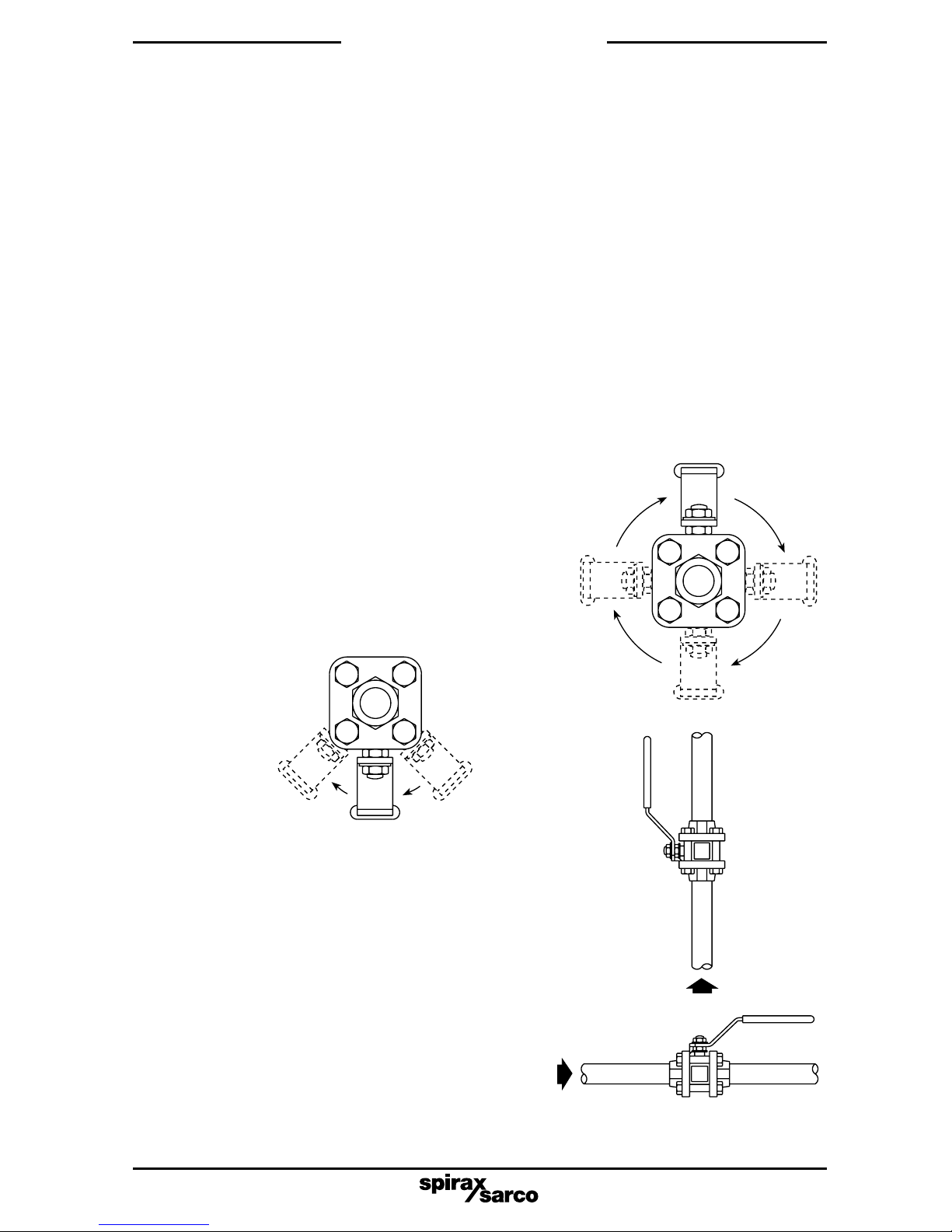
Install the valve with the handle in a suitable position. The preferred position is with the spindle
vertical. The valve can be installed in any position for gas service (see Fig. 4 below).
When used on steam services:
1. Fit a trapped drain pocket upstream of the valve.
2. Open valve slowly to prevent the risk of waterhammer damage.
3. Installation
Fig. 4 Correct installation for gas service
Do not mount the valve upside down for
liquid service (Fig. 3).
Valves should be installed into the pipeline
in the fully closed position. Prior to welding
socket an butt weld valves into the pipeline,
it will be necessary to:
1. Dismantle the end caps from the body.
2. Remove the seats and body gasket.
3. Weld each end cap to the pipeline.
4. Replace the seats and body gasket.
5. Reassemble.
Always open valves slowly to avoid system
shocks.
Fig. 3 Incorrect installation for liquid service

IM-P133-61 ST Issue 110
6. Maintenance
Note: Before actioning any maintenance programme observe
the 'Safety information' in Section 1.
6.1 General information
As with all mechanical devices, regular maintenance is the most efficient means of ensuring
continued operational efficiency.
Regular scheduled inspection of all valves is essential especially on valves which are operated
only occasionally.
6.2 General maintenance
Maintenance work can be carried out without removing the complete ball valve from the
pipeline. Remove the two upper bolts and nuts (15 and 16) and loosen the lower two.
The complete body assembly can then be removed and any new parts fitted.
Flanged valves
To proceed with maintenance work, the complete flanged valve requires removal from the
pipeline. Remove the 4 nuts (16), the complete body assembly can now be removed and new
parts fitted.
6.3 To replace seats and body gasket
- Remove the body as described in Section 6.2.
- With the body removed, remove the seats (5) and body gasket (19).
- Fit new seats (5) and body gasket (19), pushing them into the body recesses.
6.4 To replace stem seals
- Remove the body as described in Section 6.2.
- Remove the nuts (9 and 11), and the two belleville washers (8).
- Replace the stem seals (6 and 22).
6.5 Reassembly
Reassemble in reverse order to instructions given above. The securing bolts and nuts (15 and
16) should be tightened to the recommmended torques shown in Table 1 opposite.
After 24 hours in service, retighten body bolts.
4. Commissioning
After installation or maintenance ensure that the system is fully functioning. Carry out tests
on any alarms or protective devices.
5. Operation
The valve is operated manually by a handle. Special care must be taken to ensure that the
movement is made in the correct direction.
The valve can be used as an on/off valve, and can be operated fully open, or fully closed.

IM-P133-61 ST Issue 1 11
Table 1 Recommended tightening torques
Item no. Part Size N m (lbf ft)
¼", ", ½" RB 10 7.4
½" FB ¾" RB 10 7.4
15 Securing bolts ¾" FB 1" RB 25 18.0
16 Nuts 1" FB 1¼" RB 25 18.0
1¼" FB 1½" RB 40 30.0
1½" FB 2" RB 57 42.0
2" FB 2½" RB 75 55.0
¼", " RB 10.8 - 13.5 8 - 10
½", ¾" RB 10.8 - 13.5 8 - 10
9 Nut ¾" FB 1" RB 17.5 - 20.3 13 - 15
11 Stem nut 1" FB 1¼" RB 17.5 - 20.3 13 - 15
1¼" FB 1½" RB 17.5 - 20.3 13 - 15
1½" FB 2" RB 34 - 40 25 - 29.5
2" FB 2½" RB 40 - 47 29.5 - 34.6
Fig. 5
15
9
11
16
6
22
8
6
19 5 5 19

IM-P133-61 ST Issue 112
7. Spare parts
The spare parts available are shown in solid outline. Parts drawn in broken line are not
supplied as spares.
Available spare
Seat, stem seals and body gasket set 5, 6, 19, 22
How to order spares
Always order spares by using the description given in the column headed 'Available spare'
and state the size and type of ball valve required.
Example: 1 - Seat, stem seals and body gasket set for a Spirax Sarco ½" M10Si2FB ISO
ball valve.
1955
6
6
22
19
Fig. 6 M10Si and M10Vi ISO shown.
Please note: The M10Si automation has the same spare parts as indicated above.
 Loading...