

Page 1
IM-P330-74 MI Issue 1
1
© Copyright 2009
Printed in the UK
Flowin 2
Natural Gas Flowmeter
Essential Installation Guide
IM-P330-74
MI Issue 1
3309851/1
This document must be read in conjunction with IM-P330-73.
Warning
To avoid the risk of injury to personnel or damage to plant or equipment, the safety
information and technical data in the Installation and Maintenance Instructions
(IM-P330-73) should be read and assessed before attempting any installation work.
Caution
To avoid the risk of damage or loss of accuracy, the installation and commissioning
guidelines in the IM-P330-73 should be read and understood.
Essential installation guidelines
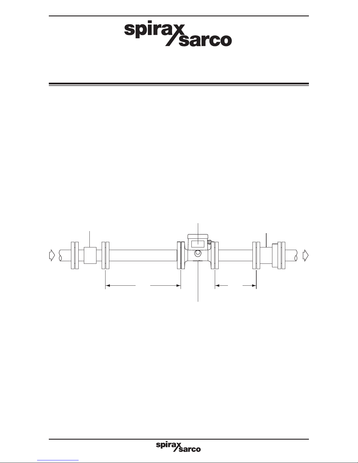
The flowmeter may be installed in a horizontal or vertical pipeline, with flow in any direction.
The preferred orientation for a Flowin 2 natural gas flowmeter is in a horizontal pipeline, with
the flowmeter display facing either upwards or downwards as illustrated in Figure 1.
Before powering up the Flowin 2 for the first time, complete the following checklist:
1. Are all required connections made?
(a) Loop?
(b) Pulse? (if required)
(c) Grounding to earth of RF braiding at the Flowin end (only) of the loop and pulse cables?
(d) Flange earth connections?
2. Are all the connections secure?
3.
Is the polarity of all connections correct?
4. Check that the earth resistance is in accordance with the technical data in IM-P330-73.
5.
Ensure there is no possibility of a short circuit occurring when the PCB housing is refitted.
6.
Refit the PCB housing to the flowmeter body in the orientation desired before ‘powering
up’ the flowmeter.
Fig. 1
Caution: Maximum permissible flange bolt tightening torque is 160 N m
Filter 250 micron
Downstream distance
Check valve
3'D'
Location of
flowmeter data label
Upstream distance
6'D'
D = Nominal bore of the pipe
Location of cast flow
arrow
Page 2
IM-P330-74 MI Issue 1
2
Please note: This document must be read in conjunction with IM-P330-73
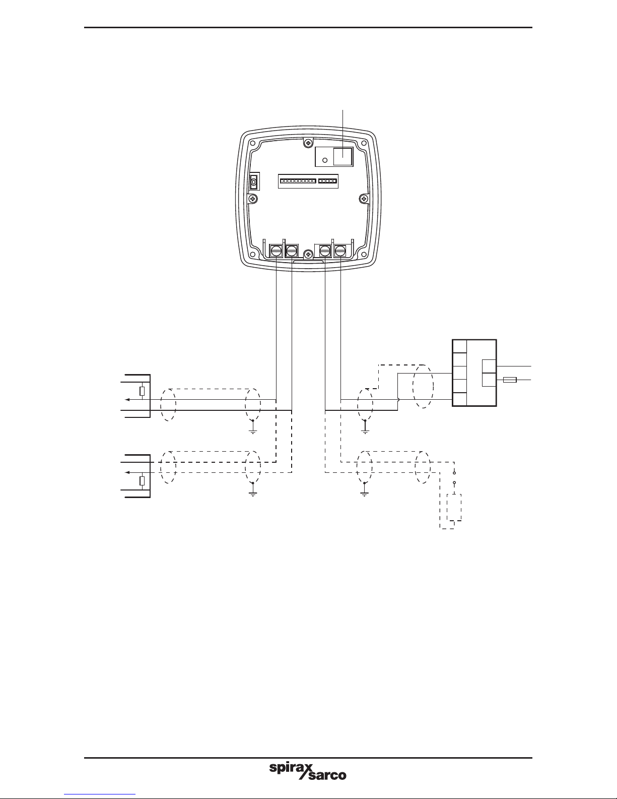
Caution – The Flowin end of all shielded cables must be grounded to the earth points provided,
as described in Section 3 of the Information and Maintenance Instructions (IM-P330-73),
otherwise the EMC performance of the Flowin 2 will be impaired, possibly resulting in flowmeter
damage or loss of accuracy.
The Flowin 2 must be earthed to the installation pipework, using the braided cables, shakeproof washers, and the hexagon screws supplied.
Recommended specification of loop power supply and pulse output cables
The loop power supply and pulse output cables must be: 7-strand, screened, twisted pair
with a cross sectional area of 0.5 mm
2
. The screen must be earthed at the Flowin end of the
cable only. The maximum cable length must not be greater than 300 m, but in practice is
governed by the number of loop devices, cable capacitance and total network resistance.
EIA 232 (RS232)
Communication port
(RJ11 socket)
Remote NPN input
(maximum 28 V)
Fig. 2
Remote PNP input
(maximum 28 V)
OR
Loop
powered
4 – 20 mA
display unit
or chart
recorder
9 - 28 Vdc
+
-
R
R
230 V
50 Hz
+
-
1
2
3
4
5
Power
0 Volts
Fuse
1 A
Power
0 Volts
R 10 K
OR
M750 display
unit with
4 - 20 mA active
input (supplying
current loop)
N
L
Pulse Loop
+ - +-
 Loading...