


IM-P612-04 ST Issue 12
1
1. Safety information
2. Product information
3. Operation
4. Installation
•
Closed loop steam systems only
5. Commissioning
6. Maintenance
7. Replacement of spares (1):
•
Cover gasket
•
Inlet swing check valve
•
Spring and actuator arm
•
Floats
8. Replacement of spares (2):
•
Trap and outlet check valve
mechanism
•
Steam inlet / exhaust valves and
seats
9. Fault finding guide
IM-P612-04
ST Issue 12
6120250/12
© Copyright 2017
Printed in GB
APT14, APT14HC and APT14SHC
Automatic Pump Traps
Installation and Maintenance Instructions

IM-P612-04 ST Issue 12
2
Safe operation of these products can only be guaranteed if they are properly installed,
commissioned, used and maintained by qualified personnel (see Section 1.11) in
compliance with the operating instructions. General installation and safety
instructions for pipeline and plant construction, as well as the proper use of tools
and safety equipment must also be complied with.
1.1 Intended use
Referring to the Installation and Maintenance Instructions, name-plate and Technical
Information Sheet, check that the product is suitable for the intended use/application.
The products listed below fully comply with the requirements of the European
Pressure Equipment Directive 97/23/EC, ATEX Directive 94/9/EC and carry the
and marks when so required.
The products fall within the following Pressure Equipment Directive categories:
Product
Group 1
Liquids
Group 2
Gases
Group 1
Gases
Group 2
Liquids
APT14 - 1 - SEP
APT14HC - 2 - SEP
APT14SHC - 2 - SEP
DCV10
DN40 PN25 rated - SEP - SEP
DN50 Class 300 rated - 1 - SEP
Motive strainer DN15 SEP SEP SEP SEP
Product marking per ATEX Directive 94/9/EC II 2G CT3.
i) The products have been designed for use on steam, air and water/condensate
which are in Group 2 of the above mentioned Pressure Equipment Directive. The
products’ use on other fluids may be possible but, if this is contemplated, Spirax
Sarco should be contacted to confirm the suitability of the product for the
application being considered.
ii) Check material suitability, pressure and temperature and their maximum and
minimum values. If the maximum operating limits of the product are lower than
those of the system in which it is being fitted, or if malfunction of the product
could result in a dangerous overpressure or overtemperature occurrence, ensure
a safety device is included in the system to prevent such over-limit situations.
iii) Determine the correct installation situation and direction of fluid flow.
iv) Spirax Sarco products are not intended to withstand external stresses that may
be induced by any system to which they are fitted. It is the responsibility of the
installer to consider these stresses and take adequate precautions to minimise
them.
v) Remove protection covers including cardboard support flanges from all
connections before installation.
1. Safety information

IM-P612-04 ST Issue 12
3
1.2 Access
Ensure safe access and if necessary a safe working platform (suitably guarded)
before attempting to work on the product. Arrange suitable lifting gear if required.
1.3 Lighting
Ensure adequate lighting, particularly where detailed or intricate work is required.
1.4 Hazardous liquids or gases in the pipeline
Consider what is in the pipeline or what may have been in the pipeline at some
previous time. Consider: flammable materials, substances hazardous to health,
extremes of temperature.
1.5 Hazardous environment around the product
Consider: explosion risk areas, lack of oxygen (e.g. tanks, pits), dangerous gases,
extremes of temperature, hot surfaces, fire hazard (e.g. during welding), excessive
noise, moving machinery.
1.6 The system
Consider the effect on the complete system of the work proposed. Will any proposed
action (e.g. closing isolation valves, electrical isolation) put any other part of the
system or any personnel at risk?
Dangers might include isolation of vents or protective devices or the rendering
ineffective of controls or alarms. Ensure isolation valves are turned on and off in a
gradual way to avoid system shocks.
1.7 Pressure systems
Ensure that any pressure is isolated and safely vented to atmospheric pressure.
Consider double isolation (double block and bleed) and the locking or labelling of
closed valves. Do not assume that the system has depressurised even when the
pressure gauge indicates zero.
1.8 Temperature
Allow time for temperature to normalise after isolation to avoid danger of burns.
1.9 ools and consumables
Before starting work ensure that you have suitable tools and/or consumables available.
Use only genuine Spirax Sarco replacement parts.
1.10 Protective clothing
Consider whether you and/or others in the vicinity require any protective clothing
to protect against the hazards of, for example, chemicals, high/low temperature,
radiation, noise, falling objects, and dangers to eyes and face.

IM-P612-04 ST Issue 12
4
1.11 Permits to work
All work must be carried out or be supervised by a suitably competent person.
Installation and operating personnel should be trained in the correct use of the
product according to the Installation and Maintenance Instructions.
Where a formal 'permit to work' system is in force it must be complied with. Where
there is no such system, it is recommended that a responsible person should know
what work is going on and, where necessary, arrange to have an assistant whose
primary responsibility is safety.
Post 'warning notices' if necessary.
1.12 Handling
Manual handling of large and/or heavy products may present a risk of injury. Lifting,
pushing, pulling, carrying or supporting a load by bodily force can cause injury
particularly to the back. You are advised to assess the risks taking into account the
task, the individual, the load and the working environment and use the appropriate
handling method depending on the circumstances of the work being done.
Please note
For specific details relating to the weight and internal mechanism of these products,
see Section 2.
Product specific - safe lifting information
Please note that the Spirax Sarco APT14 automatic pump trap units come complete
with holes which may be tapped or untapped. These holes may be used for lifting
purposes at the sole risk and responsibilty of the purchaser.
The purchaser is responsible for the selection and use of the correct eye-bolt or
shackle combination and is, in whole, responsible for all lifting operations and
operator competency at their location. Spirax Sarco will ensure that any tapped hole
will have a spot face larger than the shoulder of a standard eye-bolt to allow seating
down to the shoulder. However, it should not be assumed that an eye-bolt is suitable
for lifting the product simply on the basis of shoulder size.
Spirax Sarco will accept no responsibility for loss or damage real or imagined, caused
by incorrect or inappropriate lifting of our products.
Spirax Sarco will ensure that the tapped holes provided are clearly marked with the
exact size and thread form. We will also carry out in conjunction with a third party,
a test on a sample of each product so provided and make available a copy of the test
procedure and test certificate on request.
Furthermore and without obligation Spirax Sarco will attach to each product provided
with such holes, threaded or otherwise, a disclaimer affixed to the product explaining
the purchaser's duty under the LOLER regulations for safe off-loading and lifting of
the product at their premises.

IM-P612-04 ST Issue 12
5
1.13 Residual hazards
In normal use the external surface of the product may be very hot. If used at the
maximum permitted operating conditions the surface temperature of these products
may reach temperatures of 200 °C (392 °F).
These products are not self-draining. Take due care when dismantling or removing
the product from an installation (refer to 'Maintenance instructions').
1.14 Freezing
Provision must be made to protect products which are not self-draining against
frost damage in environments where they may be exposed to temperatures below
freezing point.
1.15 Disposal
Unless otherwise stated in the Installation and Maintenance Instructions, this product
is recyclable and no ecological hazard is anticipated with its disposal
providing due care is taken.
1.16 Returning products
Customers and stockists are reminded that under EC Health, Safety and Environment
Law, when returning products to Spirax Sarco they must provide information on any
hazards and the precautions to be taken due to contamination residues or mechanical
damage which may present a health, safety or environmental risk. This information
must be provided in writing including Health and Safety data sheets relating to any
substances identified as hazardous or potentially hazardous.

IM-P612-04 ST Issue 12
6
2.1 General description
The Spirax Sarco automatic pump trap is a flanged or screwed displacement receiver
pressure rated to PN16. The unit is capable of automatically trapping or pumping, depending
on pipeline conditions. The unit is operated by steam and is used to remove condensate
from process plant under all operating conditions including vacuum.
2. Product information
Fig. 1 APT14 shown
Design compliance
The shell of the product has been designed in accordance with A.D. Merkblatter/ASME VIII.

IM-P612-04 ST Issue 12
7
Optional extra
Both the APT14 and APT14HC are available with the body and cover coated with
electroless nickel plate (ENP). This option, when required, will be denoted as APT14
ENP and APT14HC ENP respectively and must be stated at the time of order placement.
The APT14, APT14HC and APT14SHC are available with the body drilled, tapped
and plugged to accept sight level gauges. Note: Sight level gauges can not be fitted
retrospectively to the standard APT14, APT14HC or APT14SHC.
Sight level gauges, supplied separately, are available for the APT14, APT14HC or
APT14SHC. For further details contact Spirax Sarco.
Standards
These products fully comply with the requirements of the European Pressure Equipment
Directive 97/23/EC, ATEX Directive 94/9/EC and carry the and marks when
so required.
Certification
These products are available with certification to EN 10204 3.1. Note: All certification /
inspection requirements must be stated at the time of order placement.
2.2 Sizes and pipe connections
Model
and body
material
Inlet and outlet sizes
and pipe connections
Motive/exhaust
APT14
SG iron
Flanged
DN40 inlet x DN25 outlet
EN 1092 PN16 BSP or NPT DN15 (½")
ASME B 16.5 (ANSI) 150 NPT DN15 (½")
JIS 10 (JIS B 2210) BSP DN15 (½")
KS 10 (KS B 1511) BSP DN15 (½")
Screwed
1½" inlet x 1" outlet
BSP (BS 21 parallel) BSP DN15 (½")
NPT NPT DN15 (½")
APT14HC
SG iron
Flanged
DN50 inlet x DN40 outlet
EN 1092 PN16 BSP DN15 (½")
ASME B 16.5 (ANSI) 150 NPT DN15 (½")
APT14SHC
Carbon
steel
JIS 10 (JIS B 2210) BSP DN15 (½")
KS 10 (KS B 1511) BSP DN15 (½")

IM-P612-04 ST Issue 12
8
2.3 Pressure / temperature limits APT14 and APT14HC (SG iron) - see Section 2.4 for the APT14SHC
The product must not be used in this region.
The product should not be used in this region or beyond its operating range as
damage to the internals may occur.
A - D Flanged PN16.
B - D Flanged JIS/KS 10.
C - D Flanged ANSI 150.
Temperature °C
Pressure bar g
A
Steam
saturation
curve
C
D
Pressure psi g
Temperature °F
B

IM-P612-04 ST Issue 12
9
Body design conditions
PN16
Maximum motive inlet pressure
13.8 bar g (200 psi g)
PMA Maximum allowable pressure
16 bar g @ 120 °C (232 psi g @ 248 °F)
TMA Maximum allowable temperature
300 °C @ 12.8 bar g (572 °F @ 186 psi g)
Minimum allowable temperature
Note: For lower temperatures consult Spirax Sarco.
-10 °C (14 °F)
PMO
Maximum operating pressure for
saturated steam service
13.8 bar g @ 198 °C (200 psi g @ 388 °F)
Maximum backpressure - for standard pumps
Note: For higher backpressures contact Spirax Sarco
5 bar g (72.5 psi g)
TMO
Maximum operating temperature for
saturated steam service
198 °C @ 13.8 bar g (388 °F @ 200 psi g)
Minimum operating temperature
Note: For lower temperatures consult Spirax Sarco.
-10 °C (14 °F)
Temperature limits (Ambient )
-10 °C to 200 °C (14 °F to 392 °F)
Designed for a maximum cold hydraulic test pressure of:
24 bar g (348 psi g)
Filling/
Installation
head
Recommended filling head above the pump
(from the base of the receiver/process)
0.3 m (12")
Maximum recommended installation head
(from the base of the pump) for higher
installation heads refer to Spirax Sarco
1 m (39")
Minimum installation head required (from the
base of the pump)
0.2 m (8")

IM-P612-04 ST Issue 12
10
2.4 Pressure / temperature limits APT14SHC (Carbon steel) - see Section 2.3 for the APT14 and APT14HC
Temperature °C
Pressure bar g
Pressure bar g
Temperature °C
D
Pressure psi g
Temperature °F
Steam
saturation
curve
Pressure psi g
D
C
B
A
Steam
saturation
curve
Temperature °F
The product must not be used in this region.
The product should not be used in this region or beyond its operating range as
damage to the internals may occur.
A - D Flanged PN16.
B - D Flanged JIS/KS 10.
C - D Flanged ANSI 150.

IM-P612-04 ST Issue 12
11
Body design conditions
PN16
Maximum motive inlet pressure
13.8 bar g (200 psi g)
PMA Maximum allowable pressure
16 bar g @ 120 °C (232 psi g @ 248 °F)
TMA Maximum allowable temperature
300 °C @ 12.8 bar g (572 °F @ 186 psi g)
Minimum allowable temperature
Note: For lower temperatures consult Spirax Sarco.
-10 °C (14 °F)
PMO
Maximum operating pressure for
saturated steam service
13.8 bar g @ 198 °C (200 psi g @ 388 °F)
Maximum backpressure - for standard pumps
Note: For higher backpressures contact Spirax Sarco
5 bar g (72.5 psi g)
TMO
Maximum operating temperature for
saturated steam service
198 °C @ 13.8 bar g (388 °F @ 200 psi g)
Minimum operating temperature
Note: For lower temperatures consult Spirax Sarco.
-10 °C (14 °F)
Temperature limits (Ambient )
-10 °C to 200 °C (14 °F to 392 °F)
Designed for a maximum cold hydraulic test pressure of:
24 bar g (348 psi g)
Filling/
Installation
head
Recommended filling head above the pump
(from the base of the receiver/process)
0.3 m (12")
Maximum recommended installation head
(from the base of the pump) for higher
installation heads refer to Spirax Sarco
1 m (39")
Minimum installation head required (from the
base of the pump)
0.2 m (8")

IM-P612-04 ST Issue 12
12
2.4 Nominal capacities
For full capacity details for a specific application consult Spirax Sarco. To accurately size
the pump trap, the following data is required.
1.Installation head available, from the base of the pump trap to the centre line of the heat
exchanger / process condensate outlet (metres, feet or inches). If the outlet is mounted
vertically, then this should be from the base of the pump to the face of the outlet.
2. Motive steam pressure available to power the pump trap (bar g or psi g).
3. Total backpressure in the condensate return system (bar g or psi g). See note below.
4. Heat exchanger full-load operating pressure (bar g or psi g).
5. Heat exchanger maximum steam load (kg/h or lb/h).
6. Minimum temperature of secondary fluid. ( °C).
7. Maximum controlled temperature of secondary fluid ( °C or °F).
Model APT14 APT14HC and APT14SHC
Pump discharge/cycle
5 litres
(1.1 gallons)
8 litres
(1.76 gallons)
At:
1 metre installation head
5 bar g motive pressure
1 bar g total
backpressure
Maximum trapping
capacity
4 000 kg/h
(8 820 lb/h)
Maximum trapping
capacity
9 000 kg/h
(19 845 lb/ h)
Maximum pumping
capacity
1 100 kg/h
(2 425 lb/h)
Maximum pumping
capacity
2 800 kg/h
(6 174 lb / h)
Note:
The capacities detailed within the above Table are only given as a guide. They are based
on the installation parameters shown in the left hand column.
Achieved capacities will differ if any of the installation parameters change. For specific
capacities and application details, contact Spirax Sarco.
The total lift or backpressure BP (static head plus pressure head in the return system)
must be below the motive fluid inlet pressure to allow pump capacity to be achieved.
BP (backpressure) = (H x 0.098 1 m) + (P) + (Pf)
Height (H) in metres x 0.098 1 plus pressure (P) bar g in the return line, plus downstream
piping friction pressure drop (Pf) in bar.
(Pf can be ignored if the downstream pipework is less than 100 metres to a non-flooded
condensate return and has been sized to take into account the effect of flash steam at the
heat exchanger's full-load operating conditions.)

IM-P612-04 ST Issue 12
13
2.5 Dimensions / weights
Metric (approximate) in mm and kg
Model
A B C D E F G H I J Weight
PN16 ANSI
APT14
Screwed 350 19 8 246 385 304 258 57 250 - - 19 8 45
Flanged 389 198 246 385 304 258 57 250 - - 198 45
APT14HC Flanged 476 198 270 400 335 261 57 275 31.5 45 198 65
APT14SHC Flanged 508 206 278 407 351 261 57 275 31.5 45 206 105
Imperial (approximate) in inches and lbs
APT14
Screwed 13.78 7. 8 9.69 15.16 11. 97 10.16 2.24 9.84 - - 7. 8 0 99.26
Flanged 15. 31 7. 8 9.69 1 5.16 11. 9 7 10.16 2.24 9.84 - - 7. 8 0 99.26
APT14HC Flanged 18.74 7. 8 10.63 15.75 13.1 9 10.27 2.24 10.83 1.24 1.77 7. 8 0 143.33
APT14SHC Flanged 99.9 8.1 10.94 16.62 13.82 10.27 2.24 10.83 1.24 1.77 8 .11 231.53
Motive
steam
supply
B
D
F
E
H
I
Exhaust
C
J
Fig. 2
A
G
Note:
Installation of
a DN40 outlet
check valve
type DCV10
is required
for the
APT14HC and
APT14SHC
only
S E
Withdrawal
distance
IM-P612-04 ST Issue 12
14
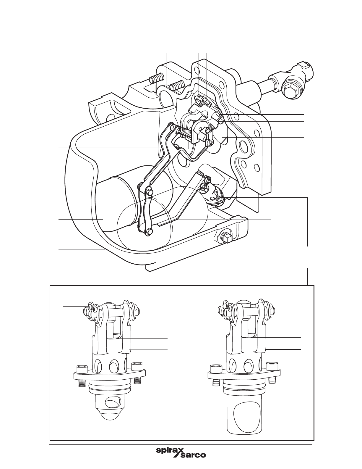
2.6 Materials
No. Part Material
1 Cover
APT14 SG iron en js 1025 or ASTM A395
APT14HC SG iron en js 1025 or ASTM A395
APT14SHC Carbon steel en 1.0619+N or ASTM A216 WCB
2 Cover gasket Graphite laminated with stainless steel insert
3 Body
APT14 SG iron en js 1025 or ASTM A395
APT14HC SG iron en js 1025 or ASTM A395
APT14SHC Carbon steel en 1.0619+N or ASTM A216 WCB
4
Cover bolts Stainless steel ISO 3506 Gr. A2 70
4 x location pins
(APT14SHC only)
Stainless steel 304
5 Pump lever Stainless steel BS 1449 304 S15
6 Float Stainless steel BS 1449 304 S15
7 Trap lever Stainless steel BS 1449 304 S15
8 Tra p 2nd stage valve Stainless steel ASTM A276 440 B
9 Trap housing Stainless steel BS 3146 ANC 2
10 Ball (APT14 only) Stainless steel ASTM A276 440 B
11 Seat (inlet check valve) Stainless steel AISI 420
12 Flap (inlet check valve) Stainless steel BS 3146 ANC 4B
13 Pump mechanism bracket Stainless steel BS 3146 ANC 4B
14 Spring (pump) Stainless steel BS 2056 302 S26 Gr. 2
15 Split pin Stainless steel BS 1574
16 Exhaust seat Stainless steel BS 970 431 S29 or ASTM A276 431
For parts 17 to 29, go to pages 16 and 17
IM-P612-04 ST Issue 12
15
3
6
14
5
1
24
13
16
7
9
8
10
15
APT14
11
APT14HC and APT14SHC
9
8
15
Trap
mechanism
Fig. 3

IM-P612-04 ST Issue 12
16
For parts 1 to 16, go to pages 14 and 15
2.6 Materials
No. Part Material
17 Inlet valve and seat assembly Stainless steel
18 Exhaust valve Stainless steel BS 3146 ANC 2
19 Valve seat gasket Stainless steel BS 1449 409 S19
20 Pump mechanism bolt Stainless steel ISO 3506 Gr. A2 70
21 Trap housing bolt Stainless steel BS 6105 A4 80
22 Tr a p 1st stage valve Stainless steel BS 970 431 S29 or ASTM A276 431
23 'O' ring EPDM
24 Actuator arm Stainless steel BS 3146 ANC 2
25 Name-plate Stainless steel BS 1449 304 S16
26 Drain plug Steel DIN 17440 1.4571
27 Inlet valve spring Stainless steel
28 Motive strainer
APT14 SG iron
APT14HC SG iron
APT14SHC Carbon steel
29
DCV10
(APT14HC and APT14SHC only)
Stainless steel
(not shown)
2.7 Disposal
There are no hazardous materials used in the construction of this product. Any unwanted
material should be recycled or disposed of in an environmentally friendly manner as specified
in Section 1, Safety information.

IM-P612-04 ST Issue 12
17
18
19 28
20
21
24
25
26
27
22
23
APT14
21
17
APT14HC and APT14SHC
22
23
15
21
Trap
mechanism
Fig. 4

IM-P612-04 ST Issue 12
18
3. Operation
Step 1 (Figure 5)
The APT14, APT14HC and
APT14SHC automatic pump trap
operates on a positive displacement
principle. Condensate enters the
body through the inlet swing check
valve causing the float to rise.
The float is connected to the trap
mechanism via a multi-link pivot.
If the upstream system pressure
PS is sufficient to overcome the
backpressure PB (Figure 4), the
build up of condensate will be
discharged through the opening two
stage trap mechanism.
In this way, the float will
automatically modulate according to
the rate of condensate entering the
unit, controlling the rate of opening
and closure of the trap.
Step 3 (Figure 7)
However, with the APT14, APT14HC and
APT14SHC, the condensate simply fills
the main chamber - lifting the float until the
changeover linkage is engaged, opening
the motive inlet and closing the exhaust
valve.
Step 2 (Figure 6)
With some temperature controlled
equipment, it is possible for the
system pressure PS to be lower
than the backpressure at PB
(Figure 6).
If this occurs a standard trap will
stall allowing the condensate to
flood the equipment being drained.
Fig. 5 APT14 shown
Fig. 6 APT14 shown
Fig. 7 APT14 shown
Condensate
inlet PS
Exhaust
Condensate
outlet PB
Condensate
inlet PS
Exhaust
Condensate
outlet PB
Motive
steam
inlet

IM-P612-04 ST Issue 12
19
Step 4 (Figure 8)
The snap action mechanism ensures
a rapid change from the trapping
mode to the active pumping mode.
With the motive inlet valve open, the
pressure in the APT14, APT14HC
and APT14SHC increases above
the total backpressure and the
condensate is forced out through
the trap seat into the plant’s return
system.
Step 5 (Figure 9)
As the condensate level falls
within the main chamber, the
float re-engages the change
over linkage, causing the motive
inlet to close and the exhaust
valve to open.
Step 6 (Figure 10)
As the pressure inside the APT14
equalises with the condensate inlet
pressure through the open exhaust
valve, condensate re-enters via
the inlet swing check valve. At the
same time the outlet ball check
valve (APT14 only) ensures no
condensate can drain back into the
main chamber and the trapping or
pumping cycle begins again.
Note: The APT14HC and
APT14SHC requires an external
Spirax Sarco DN40 disc check
valve to be fitted to the condensate
outlet, between the flanges.
Fig. 10 APT14 shown
Fig. 9 APT14 shown
Fig. 8 APT14 shown
Motive
steam
inlet
Condensate
inlet PS
Exhaust
Condensate
outlet PB
Condensate
inlet PS
Exhaust
Condensate
outlet PB
Return to Step 1.

IM-P612-04 ST Issue 12
20
4. Installation
Important - safety note
Please read Section 1.12 regarding the safe lifting of this product before actioning
any installation or maintenance procedure.
Before any installation or maintenance procedure, always ensure that all steam or
condensate lines are isolated.
Ensure any residual internal pressure in the product or connecting lines is carefully
relieved. Also ensure any hot parts have cooled to prevent risk of injury from burns.
Always wear appropriate safety clothing before carrying out any installation or
maintenance work.
Note: If pumping a potentially explosive media, the motive supply media must be an
inert gas with no oxygen present.

IM-P612-04 ST Issue 12
21
Motive IN
Strainer fitted with 100 mesh screen.
Note: The APT's are all supplied with a strainer close coupled
to the steam inlet connection.
† Minimum installation head
0.2 m (8") from base of pump.
Recommend minimum 0.3 m,
maximum 1 m.
Condensate
outlet
Spirax Sarco sized length
of pipe to act as a reservoir
Balance
line
Exhaust
OUT
Condensate
inlet
Strainer
Outlet DCV10 between flanges (APT14HC and
APT14SHC only)
An air vent must be fitted higher than the inlet to the process.
†
Fig. 11
*Trapped motive steam supply
Soft sealing flanged or screwed DCV
0.2 m
(8")
It is recommended that the reservoir be installed at
least 1 pipe diameter below the process outlet, but
as high as possible above the APT14, APT14HC or
APT14SHC inlet (up to 1 metre (40")).

IM-P612-04 ST Issue 12
22
4.1 Inlet piping
To prevent condensate backing up into the equipment being drained, it is recommended that
the inlet pipework is sufficiently sized to accumulate condensate during the pump’s discharge
cycle. Generally a length and diameter of pipe to accommodate the following condensate
capacity will be sufficient: 4 litres (1.1 gallons) for an APT14 or 8 litres (1.76 gallons) for an
APT14HC and APT14SHC. It is recommended this condensate reservoir is situated at least
1 pipe diameter below the process outlet but as high as possible above the APT inlet (up to
1 metre (40")). It is essential that a Spirax Sarco Y-type strainer is fitted at the condensate
inlet of the APT14, APT14HC and APT14SHC, as shown in Figure 12.
4.2 Recommended installation head
An installation head of at least 0.3 m (12 ins) from the base of the unit is recommended.
Minimum 0.2 m (8") with reduced capacity; Maximum 1 m (40"). Note: During cold start-up
conditions, it is possible for hydraulic pulsing of the inlet check valve to occur. It is advisable
in this case to install a throttling isolation valve to reduce the filling pressure.
4.3 Connections (refer to the installation diagram, Figure 12)
The APT's have four connection ports. The DN40 (1½") - APT14 or DN50 (2") - APT14HC
and APT14SHC port should be connected to the outlet of the equipment being drained.
The DN25 (1") - APT14 or DN40 (1½") APT14HC and APT14SHC port should be connected
to the condensate return line. Flow arrows indicate the correct direction of flow. The DN15
(½") port marked (S) should be connected to a trapped motive steam supply. * It is
important to ensure this line is drained of condensate at all times using a Spirax
Sarco steam trap and filtered using a 100 mesh strainer as fitted (see Figure 11).
The screwed DN15 (½") port marked (E) should be balanced back as close as possible
to the condensate outlet of the equipment. This balance line must always be connected
to the top of the condensate pipe, as shown in Figure 11. Note: If a thermal cut out device
has been installed to protect the heat exchanger from excess temperature, then it is
important this is mounted upstream of the steam control valve and the take-off point for
the motive steam supply to the APT14, APT14HC or APT14SHC.
Filtered / trapped motive steam supply line
Removable flanged or union section for
ease of maintenance
Spirax
Sarco
APT14
•
Ensure this
steam line is
correctly drained
of condensate at
all times using a
Spirax Sarco steam
trap plus the 100
mesh strainer as
fitted to the pump
to prevent debris
entering the pump
mechanism.
Fig. 12
Suggested coupling of
motive supply and exhaust
lines
250 mm (APT14)
275 mm (apt14hc
275 mm (APT14SHC)
minimum withdrawal
distance

IM-P612-04 ST Issue 12
23
4.4 Outlet piping
It is important for the outlet piping to be correctly sized to prevent excessive backpressure
on the APT14, APT14HC or APT14SHC. This pipework should be sized to take into account
the effects of flash steam at the heat exchangers full load operating conditions and any
other equipment being discharged into the return line.
Note: A separate Spirax Sarco DN40 DCV10 check valve must be fitted to the outlet flange
of the pump body and the connecting pipework flange - APT14HC and APT14SHC only.
Ensure the DCV10 is mounted centrally between the flanges with the directional flow arrow
pointing in the direction of fluid flow. A gasket should be used both sides of the disc check
valve. For all other maintenance and technical information see IM-P601-32.
Motive IN
Strainer fitted with 100 mesh screen.
Note: The APT's are all supplied with a strainer close coupled
to the steam inlet connection.
Condensate outlet
Spirax Sarco sized length
of pipe to act as a reservoir
Balance
line
Exhaust
OUT
Condensate inlet
Strainer
Outlet DCV10 between flanges
(APT14HC and APT14SHC only)
An air vent must be fitted higher than the inlet to the process.
†
Fig. 13
*Trapped motive steam supply
Soft sealing flanged or screwed DCV
0.2 m
(8")
It is recommended that the reservoir be installed at least 1 pipe diameter below the
process outlet, but as high as possible above the APT14, APT14HC or APT14SHC inlet.
† Minimum installation head
0.2 m (8") from base of pump.
Recommend minimum 0.3 m,
maximum 1 m.

IM-P612-04 ST Issue 12
24
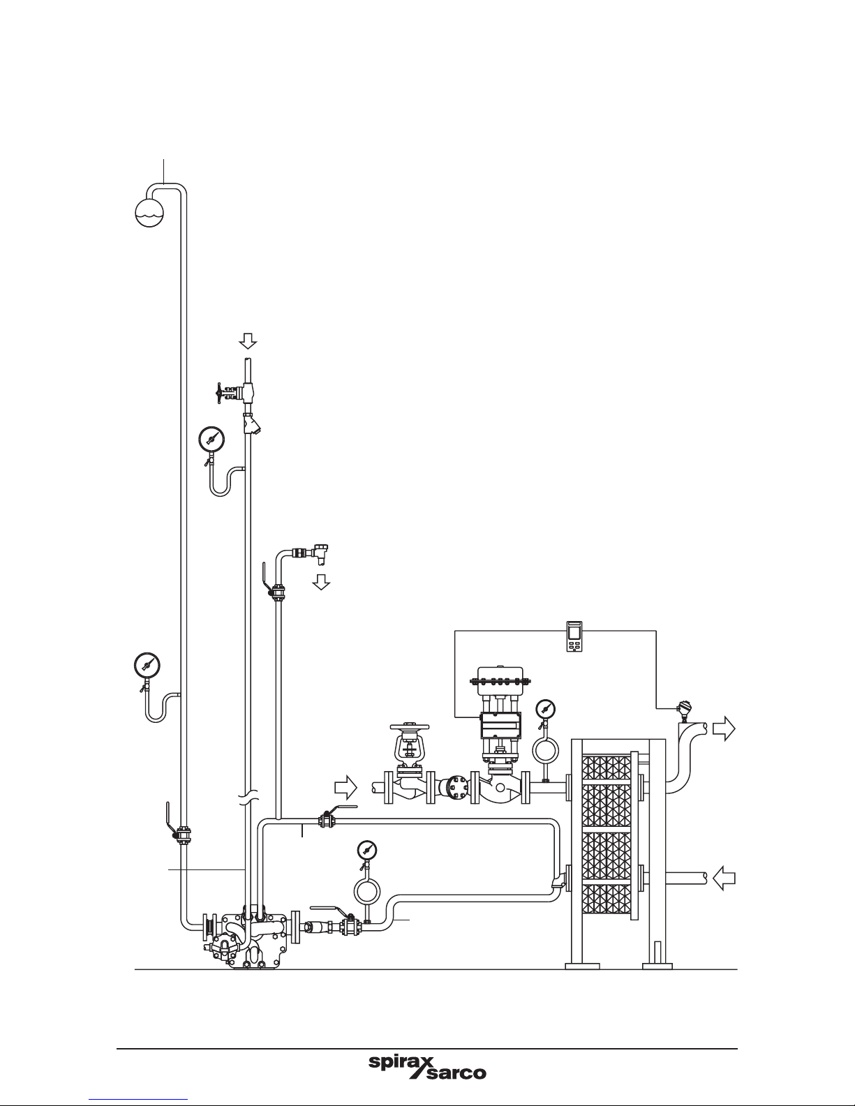
4.5 Pressure gauges
It is recommended that system pressure gauges are fitted to the motive supply, condensate
inlet and condensate outlet as shown in Figure 14.
4.6 Control of motive supply pressure
Although the APT is able to utilise motive pressures up to 13.8 bar g (200 psi g), it is highly
recommended that the motive pressure does not exceed 3 to 4 bar g (44 to 58 psi g) above
the backpressure applied to the pump. When specifying a pressure reducing valve to
reduce the motive supply pressure, the effects of pulsating flow on the pressure reducing
valve must be considered. Contact Spirax Sarco for details of recommended installation if
required. The motive supply must be drained by a suitable steam trap to ensure the motive
steam is dry. See Figure 14.
Motive IN
Strainer fitted with 100 mesh screen.
Note: The APT's are all supplied with a strainer close coupled
to the steam inlet connection.
Spirax Sarco sized length
of pipe to act as a reservoir
Balance
line
Exhaust
OUT
Condensate inlet
Strainer
Outlet DCV10 between flanges
(APT14HC and APT14SHC only)
An air vent must be fitted higher than the inlet to the process.
†
Fig. 14
Soft sealing flanged or screwed DCV
0.2 m
(8")
It is recommended that the reservoir be installed at least 1 pipe diameter below the
process outlet, but as high as possible above the APT14, APT14HC or APT14SHC inlet.
Condensate
outlet
*Trapped motive steam supply
† Minimum installation head
0.2 m (8") from base of pump.
Recommend minimum 0.3 m,
maximum 1 m.

IM-P612-04 ST Issue 12
25
4.6.1 Fail safe condition of motive supply.
When the APT14 is used to remove condensate from temperature controlled plant such
as heat exchangers, it is recommended that the motive supply to the APT is taken from a
point downstream of a fail safe high limit control valve, see Figure 15.
Fig. 15
APT motive
steam supply
Fail safe
high limit
valve
Temperature
control valve

IM-P612-04 ST Issue 12
26
5.1
After ensuring the inlet and outlet pipe connections and motive/exhaust connections
are coupled in accordance with Figures 15 and 16, slowly open the motive steam inlet
line to supply pressure to the APT14, APT14HC or APT14SHC. Ensure the exhaust/
balance line is open and not restricted in any way.
5.2
Slowly open the isolation valves in the condensate inlet and discharge lines, allowing
condensate to fill the body of the APT14, APT14HC or APT14SHC.
5.3
The APT14, APT14HC or APT14SHC is now ready to operate.
5.4
When the process plant is operational, the APT14, APT14HC or APT14SHC will
discharge condensate under all pressure conditions into the return line.
5.5
If any irregularities are observed, recheck the installation according to the
recommendations in Section 4. If the unit fails to operate, then consult the fault finding
guide Section 9.
5. Commissioning
Fig. 16
Filtered / trapped motive steam supply line
Spirax
Sarco
APT14
Ensure this steam line is correctly drained of condensate at
all times using a Spirax Sarco steam trap plus the 100 mesh
strainer as fitted to the pump to prevent debris entering the
pump mechanism.
IM-P612-04 ST Issue 12
27
Return
line
Fig. 17 APT14HC shown
Motive
IN
Condensate
outlet
Exhaust
OUT
Condensate
inlet
Trapped motive steam supply

IM-P612-04 ST Issue 12
28
6.1 Mechanisms inspection and repair (Important - safety note)
Please read Section 1.12 regarding the safe lifting of this product before actioning
any installation or maintenance procedure.
Before any installation or maintenance procedure, always ensure that all steam or
condensate lines are isolated.
Ensure any residual internal pressure in the product or connecting lines is carefully
relieved. Also ensure any hot parts have cooled to prevent risk of injury from burns.
Always wear appropriate safety clothing before carrying out any installation or
maintenance work.
When dismantling this product, care should be taken to prevent injury from the snap
action mechanism. Always handle with care.
The APT14, APT14HC and APT14SHC should be inspected periodically, intervals
dependant on application. Contact Spirax Sarco for details.
6.2 Removal and fitting of cover assembly
Please ensure the safety recommendations are observed before commencing with any
maintenance of this product.
6.3 To remove the cover assembly
1. Disconnect all connections to the cover. Remove the cover bolts using the correct
size socket, then carefully slide the cover assembly away from the body (a minimum
withdrawal distance of 250 mm for the APT14 or 275 mm for the APT14HC and
APT14SHC will be needed). Lift the cover assembly to a bench or other convenient
working surface and clamp securely, avoiding contact with the gasket face.
2. Visually inspect the mechanism for obvious damage. Check that it is free of dirt and
scale and operates freely when the floats are moved up and down.
3. Inspect the spring assembly for damage. Make sure the valves slide freely and the
spring loaded exhaust valve moves on its guide.
4. Inspect the floats to ensure they are undamaged. Check they pivot smoothly on the
pump and trap levers and they are not waterlogged.
5. Ensure the inlet swing check valve is free to move and the sealing faces of both the
seat and the flap are clean and undamaged. (If the seat is badly scored or damaged a
new cover assembly may be required).
6. Check the two stage trap module to ensure both the 1st and 2nd stage valves are free
from dirt and debris. Ensure they slide open and close smoothly.
7. It is not possible to visually check the outlet check valve without removing the trap
module (refer to Section 8 of this manual for correct removal and fitting of this part APT14 only).
8. If any of the parts appear damaged or fail to work correctly, then refer to Sections 8
and 9 of this manual for correct removal and fitting instructions.
6. Maintenance
 Loading...