


IM-P102- 04 CTLS Issue 7
1
1. Safety information
2. Installation
3. Start-up
4. Maintenance
5. Spare parts
6. Fault finding
© Copyright 2018
Printed in GB
1020026/7
37D and 37DE
Temperature Controls
Installation and Maintenance Instructions
IM - P102-04
CTLS Issue 7

IM-P102- 04 CTLS Issue 7
2

IM-P102- 04 CTLS Issue 7
3
Safe operation of these units can only be guaranteed if they are properly installed, commissioned
and maintained by a qualified person (see Section 1.11 of the attached Supplementary Safety
Information) in compliance with the operating instructions. General installation and safety
instructions for pipeline and plant construction, as well as the proper use of tools and safety
equipment must also be complied with.
Warning
The body gasket contains a thin stainless steel support ring which may cause physical injury if
not handled and disposed of carefully.
1.1 Intended use
Referring to the Installation and Maintenance Instructions, name-plate and Technical Information
sheet, check that the product is suitable for the intended use/application.
The products listed below fully comply with the requirements of the Pressure Equipment
Directive (PED) and carry the mark when so required.
The products fall within the following Pressure Equipment Directive categories:
Product
Group 1
Gases
Group 2
Gases
Group 1
Liquids
Group 2
Liquids
37D and 37DE - 2 - SEP
i) The products have been specifically designed for use on steam, air and water/condensate which
are in Group 2 of the above mentioned Pressure Equipment Directive. The products’ use on
other fluids may be possible but, if this is contemplated, Spirax Sarco should be contacted to
confirm the suitability of the product for the application being considered.
ii) Check material suitability, pressure and temperature and their maximum and minimum values.
If the maximum operating limits of the product are lower than those of the system in which it
is being fitted, or if malfunction of the product could result in a dangerous overpressure or
overtemperature occurrence, ensure a safety device is included in the system to prevent such
over-limit situations.
iii) Determine the correct installation situation and direction of fluid flow.
iv) Spirax Sarco products are not intended to withstand external stresses that may be induced
by any system to which they are fitted. It is the responsibility of the installer to consider these
stresses and take adequate precautions to minimise them.
v) Remove protection covers from all connections and protective film from all name-plates, where
appropriate, before installation on steam or other high temperature applications.
1.2 Access
Ensure safe access and if necessary a safe working platform (suitably guarded) before attempting
to work on the product. Arrange suitable lifting gear if required.
1.3 Lighting
Ensure adequate lighting, particularly where detailed or intricate work is required.
1. Safety information

IM-P102- 04 CTLS Issue 7
4
1.4 Hazardous liquids or gases in the pipeline
Consider what is in the pipeline or what may have been in the pipeline at some previous time.
Consider: flammable materials, substances hazardous to health, extremes of temperature.
1.5 Hazardous environment around the product
Consider: explosion risk areas, lack of oxygen (e.g. tanks, pits), dangerous gases, extremes of
temperature, hot surfaces, fire hazard (e.g. during welding), excessive noise, moving machinery.
1.6 Isolation
Consider whether closing isolating valves will put any other part of the system or personnel at
risk. Dangers might include; isolation of vents and protective devices or alarms. Ensure isolation
valves are turned off in a gradual way to avoid system shocks.
1.7 Pressure systems
Before attempting any maintenance consider what is or may have been in the pipeline. Ensure that
any pressure is isolated and safely vented to atmospheric pressure before attempting to maintain
the product, this is easily achieved by fitting Spirax Sarco depressurisation valves type DV (see
separate literature for details). Do not assume that the system is depressurised even when a
pressure gauge indicates zero.
1.8 Temperature
Allow time for temperature to normalise after isolation to avoid danger of burns.
1.9 Tools and consumables
Before starting work ensure that you have suitable tools and/or consumables available. Use o nly
genuine Spirax Sarco replacement parts.
1.10 Protective clothing
Consider whether you and/or others in the vicinity require any protective clothing to protect against
the hazards of, for example, chemicals, high/low temperature, radiation, noise, falling objects, and
dangers to eyes and face.
1.11 Permits to work
All work must be carried out or be supervised by a suitably competent person.
Installation and operating personnel should be trained in the correct use of the product according
to the Installation and Maintenance Instructions.
Where a formal 'permit to work' system is in force it must be complied with. Where there is no such
system, it is recommended that a responsible person should know what work is going on and,
where necessary, arrange to have an assistant whose primary responsibility is safety and who has
had specific training on pressurised systems.
Post 'warning notices' if necessary.
1.12 Handling
Manual handling of large and/or heavy products may present a risk of injury. Lifting, pushing,
pulling, carrying or supporting a load by bodily force can cause injury particularly to the back.
You are advised to assess the risks taking into account the task, the individual, the load and the
working environment and use the appropriate handling method depending on the circumstances
of the work being done.

IM-P102- 04 CTLS Issue 7
5
1.13 Residual hazards
In normal use the external surface of the product may be very hot. If used at the maximum
permitted operating conditions the surface temperature of these products may reach temperatures
of 200 °C (392 °F).
These products are not self- draining. Take due care when dismantling or removing the product
from an installation (refer to 'Maintenance instructions').
1.14 Freezing
Provision must be made to protect products which are not self-draining against frost damage in
environments where they may be exposed to temperatures below freezing point.
1.15 Disposal
These products are recyclable. No ecological hazard is anticipated with the disposal of these
products providing due care is taken.
1.16 Returning products
Customers and stockists are reminded that under EC Health, Safety and Environment Law, when
returning products to Spirax Sa rco they mus t provide inform ation on any hazards an d the precautio ns
to be taken due to contamination residues or mechanical damage which may present a health,
safety or environmental risk. This information must be provided in writing including Health and
Safety data sheets relating to any substances identified as hazardous or potentially hazardous.

IM-P102- 04 CTLS Issue 7
6
2.1 Supply (Fig. 1)
37D
The 37D Spirax Sarco temperature control is supplied with the temperature control unit and valve packed
separately, and should be assembled securing the control head to the valve by means of the three screws
supplied.
The temperature control unit is fitted with a control system having a range most suitable for the temperature
given on the order but it is not preset.
37DE
The 37DE Spirax Sarco temperature control is supplied as for the 37D but a solenoid operated valve is fitted
in the pipe between the pilot valve and the main diaphragm chamber, i.e. in series with the normal pilot valve.
The purpose of the solenoid valve is to override the pilot valve thus causing the main valve to shut off. It
can be controlled by any device capable of interrupting the supply of current to the solenoid coil such as a
thermostat, pressure switch hand clock.
The solenoid is arranged to open the valve when the coil is energised so that whatever switching device is
used it must be arranged to break the current to close the main valve. In this way the unit will always 'failsafe' i.e. will close the main valve in the event of a failure in electrical supply.
Electrical supply
It is important that the solenoid is connected to the correct voltage. The standard unit is suitable for
110 Vac or 230/250 Vac 50 Hz supply, but units for other ac voltages may be supplied to special order,
therefore always check on the supply details which are stamped on the solenoid valve name-plate before
attempting to connect up.
Electrical connection is by cable plug to DIN 43650. Remember that the valve is on a steam supply line and
in use will get hot. All wiring, connectors, etc. in close proximity to the valve should therefore be of heat
resisting type.
Earth
The solenoid valve should be adequately earthed.
Maximum pressure
When converted to the 37DE by the addition of the solenoid valve, the Spirax Sarco temperature control is
limited to a maximum pressure of 9.6 bar (139 psi).
2. General product information

IM-P102- 04 CTLS Issue 7
7
Temperature
control unit
Control
head
securing
screws
Solenoid
valve
37DE
37D
Fig. 1

IM-P102- 04 CTLS Issue 7
8
2.2 General arrangement
Fig. 2 shows the recommended installation layout to ensure satisfactory operation of the Type 37D and 37DE
temperature control. It should always be fitted in a horizontal pipeline with the main diaphragm chamber
below the line.
2.3 Pipeline sizing
The piping on both sides of the valve must be sized so that velocities do not exceed 30 m/s (98 ft/s). This
means that a properly sized valve will often be smaller than the connecting pipework.
2.4 Pipeline stresses
Line stresses such as could be caused by expansion or inadequate support should not be imposed on the
valve body.
2.5 Isolating valves
These should preferably be of the fullway type.
2.6 Removal of condensate
Ensure that the pipework is adequately drained so that the valve is supplied with dry steam.
The ideal arrangement is to fit a separator in the steam supply. If the steam is known to be dry then a drain
pocket may be adequate.
If there is a rise in the low pressure line from the valve then a further drain point should be provided to keep
the valve drained after shutdown.
2.7 Preventing dirt
The valve should be protected by a pipeline strainer with 100 mesh screen. The strainer should be fitted on
its side to prevent the accumulation of water.
2.8 Temperature ranges
The temperature control system is available in five temperature ranges as follows:
Rang e A 16 °C to 49 °C (61 °F - 120 °F)
Rang e B 38 °C to 71 °C (100 °F - 160 °F)
Rang e C 49 °C to 82 °C (120 °F - 180 °F)
Rang e D 71 °C to 104 °C (160 °F - 219 °F)
Rang e E 93 °C to 127 °C (199 °F - 261 °F)

IM-P102- 04 CTLS Issue 7
9
Steam
Steam
Bypass valve
Fullway valve
Fullway valve
Strainer with
blowdown cock
Strainer
Strainer
Separator
Strainer with blowdown cock
Fig. 2 Alternative installation fitted with a separator
Steam trap
Steam trap
Sight glass
Sight glass
Fullway valve
To process
37D temperature control
Recommended installation

IM-P102- 04 CTLS Issue 7
10
2.9 Sensor bulb
The type 37D control is fitted with a plain bulb as in Fig. 3,
but as standard this bulb is supplied with an adaptor shown
in Fig. 4, consisting of a union nipple (U), 'O' ring (V) and
gland nut (W).
2.10 Use of plain bulb
Where it is desired to use a plain bulb as in Fig. 3 the
adaptor can be removed by unscrewing the gland nut (W)
from the union nipple Fig. 4 and withdrawing each piece
of the assembly separately over the bulb.
2.11 Use of immersion bulb
Where it is desired, insert the bulb into a vessel under
pressure. Unscrew the gland nut (W) from the union
nipple (U). This will enable the union nipple to withdraw
over the bulb.
The union nipple can now be screwed into the tapping
provided at the temperature sensing point.
The union nipple is normally threaded ¾" BSP but may be
¾" NPT if specially ordered.
Insert the bulb through the union nipple (U) until the 'O'
ring (V) seats in the union nipple as shown in Fig. 4 and
screw home the gland nut (W) to compress the 'O' ring.
The gland nut needs to be little more than finger tight. Do
not overtighten otherwise damage to the 'O' ring will result.
2.12 Poc ke ts
In all cases where the temperature sensing point is in a fluid
under pressure it is best to use a pocket so that the bulb can
be withdrawn for servicing without draining down the plant.
Pockets must also be used where the medium being
controlled would attack and destroy the material from which
the bulb is constructed.
The top of the pocket is formed exactly as the union nipple
and should be screwed into the tapping (¾" BSP or ¾" NPT)
provided at the temperature sensing point.
Insert the bulb into the pocket until the 'O' ring seats in the
union nipple as Fig. 5, and screw home the gland nut (W) to
compress the 'O' ring.
The gland nut (W) will be little more than finger tight. Do
not overtighten otherwise damage to the 'O' ring will result.
Fig. 3
Fig. 4
Fig. 5
W
V
U
W
V
¾" BSP taper
NPT available
¾" BSP taper
NPT available

IM-P102- 04 CTLS Issue 7
11
2.13 Extra long pockets
Where extra long pockets are used the plain
bulb should be used and inserted the full length
of the pocket.
A split bung is provided to seal the top of the
pocket Fig. 6.
2.14 Heat conduction
Where a bulb is used in a pocket the pocket
should be filled with a heat conducting fluid,
such as thin oil or water, to improve heat
tr ans fer.
Do not fill the extended pocket Fig. 6, above
the level of the bulb.
2.15 Wall mounting sensor
Where the type 37D control is to be used to control from room
temperature the plain bulb Fig. 3 is used and a bracket and
protective shield is provided Fig. 7.
It is essential that the sensor be fitted in such a position that
it can sense the true room temperature and is not influenced
by draughts.
It is preferably fitted in the vertical position and can be fitted
either with the capillary leading from top of the sensor or
leading from the bottom.
Having decided on the sensor position fix the bracket to the
wall making sure that it is fitted in such a way that the lug
standing proud of the base will engage with the groove turned
in the sensor.
After inserting the sensor in the clips, fit the external cover
as in Fig. 8.
Fig. 6
Fig. 7
Fig. 8
Level of
fluid

IM-P102- 04 CTLS Issue 7
12
3.1
When the valve is installed and the control system is fitted with the bulb in the medium to be controlled
it may be brought into operation as follows.
In most new installations dirt collects in the steam line during construction. It is always advisable to
blow this out on initial start-up.
Remove the cap on the strainer before the steam trap, crack open the steam supply blowdown to clear
dirt, shut-off and replace cap.
It is essential that the screen in the main line strainer is not removed during this operation.
If a blowdown cock is fitted to the strainer cap as mentioned in Section 2 it can be opened to blow out
the dirt without removing the cap.
3.2
Check that the temperature scale can be easily seen.
If it is fitted in a confined space facing a wall for example the control head may be repositioned to
enable the scale to be more easily read as follows:
Undo the three screws. The control head may now be turned through 120° or 240° and the screws
tightened up.
3.3
By turning the knurled knob, set the scale opposite the pointer to the temperature at which it is desired
to control. (Where it is essential that this temperature is not exceeded it is advisable to set the control
initially some 6 °C (43 °F) lower and bring the plant up to temperature slowly).
1. Put the plant in operation in the normal way allow 30 minutes for it to settle down, then check the
temperature against a reliable thermometer - this check reading should be taken as close to the
control point as possible to ensure that both the thermometer and the sensor bulb are sensing
similar conditions.
2. Compare the thermometer reading with the scale reading on the temperature control.
3. This may be found to differ by a few degrees and if precise control is required can be adjusted by
resetting the pointer as follows:
4. Holding the control head tightly onto the pilot valve housing - slacken the three screws, just
sufficiently to enable the pointer to be moved to the right or left until the temperature indicated on
the scale corresponds with the actual temperature as shown on the sensor.
Whilst making this adjustment it is essential to hold the control head tightly onto the pilot valve
housing other wise not only will movement of the pointer be difficult but allowing the head to lift
will open the pilot valve.
5. Tighten the three screws.
6. The adjustment knob may now be reset to the required temperature. Adjustments to raise or lower
the temperature may be freely made without damage to the control system.
Important
Direct injection systems
This product contains a rust inhibitor to protect it against corrosion during storage. To avoid
any possible contamination of your product, after first blowing down the approach pipework, we
recommend that the valve is blown through thoroughly in order to remove any trace of the inhibitor.
3. Start-up

IM-P102- 04 CTLS Issue 7
13
Pilot valve assembly
Main valve screen
Main valve seat and valve head
Main diaphragms
4.1 Routine maintenance
It is recommended that the valve is dismantled once every twelve to eighteen months for a complete overhaul
and ideally this should be carried out with the valve removed from the line.
The parts that may require replacing or refurbishing are listed below:
-
Main valve seat and valve head.
-
Main valve screen.
-
Pilot valve assembly.
-
Main diaphragms.
Safety warning:
The body gasket contains a thin stainless steel
support ring which may cause physical injury if
not handled and disposed of carefully.
4. Maintenance

IM-P102- 04 CTLS Issue 7
14
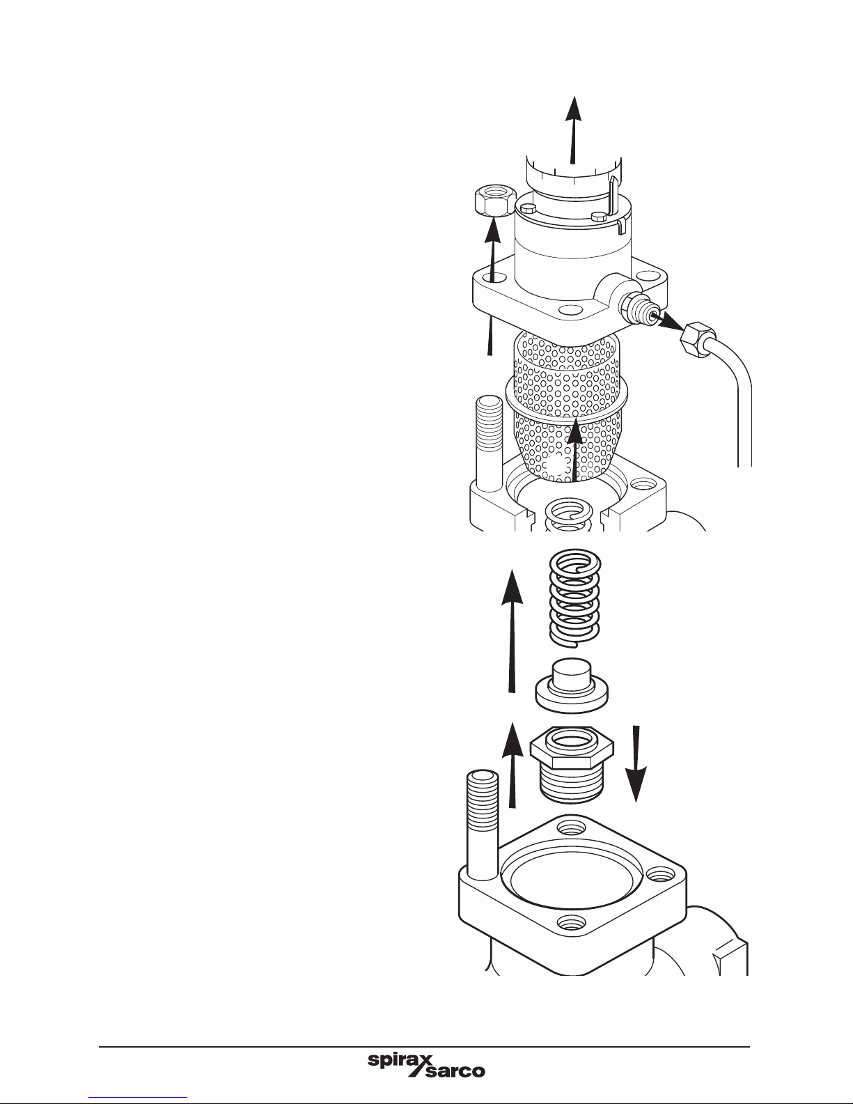
To renew the pilot valve assembly
Isolate the valve and zero the pressure. If the plant is still in operation through a bypass valve or if the medium
surrounding the bulb is hot, withdraw the sensor bulb and allow it to cool down, otherwise the control system
may be strained.
1. Undo the three screws and lift of the adjustment head.
2. Unscrew the packless gland housing (21 mm A /F) and remove with the push rod assembly and return
spring.
3. Unscrew the union and release the pipework.
4. Unscrew the nuts and remove the pilot valve housing.
5. Ensure that the main valve return spring is still in position.
6. Unscrew and remove the pilot valve assembly (20 mm A/F).
7. Screw the new pilot valve into the housing.
1
2
3
4
5
6 7

IM-P102- 04 CTLS Issue 7
15
8. Remove the screen and clean.
9. Ensure the main valve return spring is still in position.
10. Fit the new gasket.
11. Replace the screen.
12. Assemble the pilot valve housing and tighten the nuts to the torques shown in Table 1.
13. Refit the pipework and retighten the unions to ensure a steam tight seal.
14. Fit a new push rod assembly with return spring and replace the packless gland housing, tighten to
40 N m (30 lbf ft).
15. Refit the adjustment head. Bring the valve back into commission by following as many steps as are
necessary in Section 3.
Table 1 Recommended tightening torques
Size of valve Nut size Tightening torques
½", ¾", 1"
DN15, DN20, DN25 and DN32
M10 40 N m (30 lbf ft)
DN40 and DN50 M12 45 N m (33 lbf ft)
After fitting a new pilot valve seat and push rod it will be necessary to check the temperature control
points (see Section 3.3).
9
10
12
13
14
15
11
8

IM-P102- 04 CTLS Issue 7
16
To clean the strainer
Isolate the valve and zero the pressure. If the plant is
still in operation through a bypass valve or if the medium
surrounding the bulb is hot, withdraw the sensor bulb
and allow it to cool down, otherwise the control system
may be strained.
16. Unscrew the unions and release pipework.
17. Unscrew the nuts.
18. Remove the pilot valve housing complete with the
adjustment head.
19. Remove the screen and clean.
20. Ensure the gasket faces are clean.
21. Check that the main valve return spring is in position.
22. Fit a new gasket.
23. Replace the screen.
24. Assemble the pilot valve housing complete with the
spring housing assembly and tighten the nuts to the
torques shown in Table 1.
25. Refit the pipework and retighten the unions to ensure
a tight seal. Bring the valve back into commission by
following as many steps as necessary in Section 3.
16
17
18
20
21
22
24
25
19
23

IM-P102- 04 CTLS Issue 7
17
To renew or clean the main diaphragms
Isolate the valve and zero the pressure. If the plant
is still in operation through a bypass valve or if the
medium surrounding the bulb is hot, withdraw the
sensor bulb and allow it to cool down, otherwise the
control system may be strained.
26. Undo the long union nut and pull away.
27. Undo the M12 nuts and bolts.
28. Drop away the lower diaphragm chamber, the
two diaphragms, diaphragm plate and push
rod assembly.
29. Thoroughly clean the lower diaphragm chamber
making sure the contact faces are clean.
30. Replace the diaphragm plate and push rod
assembly and loosely fit the lower diaphragm
chamber on two bolts either side of the union
connection to locate spigot in recess.
31. Bring the two new diaphragms together (where
precoated sealant is applied this should face
outwards) and slide into position. If diaphragms
are not renewed, but cleaned only care must
be taken to replace diaphragms in the original
or der.
32. Push the lower diaphragm chamber home to
locate in the recess and refit M12 nuts and
bolts. Progressively and evenly tighten to a
torque of 80 - 100 N m (59 - 74 lbf ft).
33. Retighten the long union nut to ensure a steam
tight seal. Bring the valve back into commission
by following as many steps as are necessary
in Section 3.
2627
28
29
30
31
32 33
IM-P102- 04 CTLS Issue 7
18
To service or renew the main valve
and seat
Isolate the valve and zero the pressure. If the plant is
still in operation through a bypass valve or if the medium
surrounding the bulb is hot, withdraw the sensor bulb
and allow it to cool down, otherwise the control system
may be strained.
34 . Unscrew the unions and release pipework.
35. Unscrew the nuts.
36. Remove the pilot valve housing, complete with the
spring housing assembly.
37. Remove the screen and clean.
38. Remove the main valve spring and the main valve
head.
39. Remove the main valve seat. Examine the faces of
the main valve head and seat. If they are only slightly
worn both the main valve head and main seat may be
lapped on a flat plate using a fine grinding paste. If
either is badly worn or unfit for further use they will
need to be replaced.
40. Refit the valve seat and tighten to the recommended
torque shown in Table 2. Where a new part has been
fitted it will be necessary to reset the main valve
push rod to give the correct valve lift. To do this it is
necessary to expose the main diaphragm plate and
push rod assembly.
34
35
36
38
39
40
37

IM-P102- 04 CTLS Issue 7
19
Table 2 Recommended tightening torques for main seat
Size of valve Width across flats Tightening torque
½", ½" LC, DN15 & DN15LC 30 mm (1.18") (external) 110 - 120 N m (81 - 89 lbf ft)
¾" & DN20 36 mm (1.42") (external) 140 - 150 N m (103 - 111 lbf ft)
1" & DN25 19 mm (0.75") (inside) 170 - 180 N m (125 - 133 lbf ft)
DN32 24 mm (0.94") (inside) 200 - 210 N m (148 - 155 lbf ft)
DN40 30 mm (1.18") (inside) 230 - 240 N m (170 - 177 lbf ft)
DN50 41 mm (1.61") (inside) 270 - 280 N m (199 - 207 lbf ft)
41. Undo the long nuts and pull away.
42. Undo the M12 nuts and bolts.
43. Drop away the lower diaphragm chamber, the two diaphragms, diaphragm plate and the push rod
assembly.
44. Refit the push rod assembly.
45. Refit the main valve head, make sure the valve locates on seat.
46. Open the valve by pushing onto the diaphragm plate until it comes up against the stop of the body.
47. Check the valve lift (shown in Table 3) using a depth gauge.
Table 3 Valve lift
Size of valve DN15LC DN15 DN20 DN25 DN32 DN40 DN50
Lif t
2.0 mm
(0.08")
2.0 mm
(0.08")
2.5 mm
(0.1 0 " )
3.0 mm
(0.12 " )
3.5 mm
(0.14")
4.5 mm
(0.1 8 " )
5.0 mm (0.20")
Adjust if necessary by screwing push rod in or out of diaphragm plate.
41
42
43
44
45
46
47

IM-P102- 04 CTLS Issue 7
20
48. Thoroughly clean the lower diaphragm chamber
making sure the contact faces are clean.
49. Replace the diaphragm plate and the push rod
assembly and loosely fit the lower diaphragm
chamber on two bolts either side of the union
connection to locate the spigot in the recess.
50. Refit the diaphragms in exactly the same way as
when dismantled.
51. Push the lower diaphragm chamber home to locate
in the recess and refit the M12 nuts and bolts.
Progressively and evenly tighten to a torque of
75 N m.
52. Retighten the long union nut to ensure a steam
tight seal.
53. Ensure the gasket faces are clean.
54 . Refit the main valve head.
55. Replace the main valve return spring.
56. Fit a new gasket.
57. Replace the screen.
58. Assemble the pilot valve housing complete with the
spring housing assembly and tighten the nuts to the
recommended torques shown in Table 1.
59. Refit the pipework and retighten the unions to ensure
a tight seal. Bring the valve back into commission by
following as many steps as necessary in Section 3.
48
53
58
49
54
59
49
55
50
56
51 52
57

IM-P102- 04 CTLS Issue 7
21
To renew the temperature control system
Isolate the valve and zero the pressure. If the plant is still in operation through a bypass valve or if the medium
surrounding the bulb is hot, withdraw the sensor bulb and allow it to cool.
60. Undo the three screws and lift off the adjustment
head.
61. Fix in position the adjustment head of the replacement
thermostatic system. Take care that the limit stop of
the pointer ring is properly located in the slot.
62. Retighten the screws.
Bring the valve back into commission by following as
many steps that are necessary in Section 3.
With a replacement thermostatic system it may be
found that the points cannot be moved far enough
to reach the desired reading on the scale when the
medium around the bulb is at the correct temperature.
If this is so, resetting of the calibration can be carried
out using the special spanner supplied with each
replacement sensor.
63. Fix the pointer in the mid-position of its adjustment
and set the scale to indicate the required temperature.
64 . Tighten up the screws.
65. Hold the sleeve with a pair of pliers and loosen the
locking ring, using the special spanner.
66. Still holding the sleeve with the pliers, turn clockwise
if the temperature of the medium being controlled is
too high or anticlockwise if too low.
67. After resetting, tighten up the locking ring with special
spanner.
60
61
62
63
64
65
66
67

IM-P102- 04 CTLS Issue 7
22
To service or renew solenoid valve (37DE)
68. Remove the retaining nut, washer and seal and slip the entire solenoid enclosure off the solenoid base
and sub-assembly or plugnut/core tube sub-assembly.
69. Unscrew the bonnet or solenoid base sub-assembly and remove the core spring, core assembly and
body gasket. All parts are now accessible for cleaning replacement.
Replace worn or damaged parts with a complete Spare parts kit (item W) for best results.
70. Reassemble in reverse order paying careful attention to the exploded views provided.
Coil replacement
Switch off electrical power supply and disconnect coil lead wires.
71. Undo retaining nut.
72. Slip washer, insulating washers and coil off solenoid base sub-assembly. Reassemble in reverse order.
CAUTION
Solenoid must be fully reassembled as the housing is part of, and completes the magnetic circuit.
68
69
70
71
72

IM-P102- 04 CTLS Issue 7
23
Interchangeability of spares
The following table shows how in certain sizes some parts are interchangeable. For example in the line
headed 'Main diaphragm' the diaphragm used in the screwed valves ½" and ¾" is common to these sizes by
the letter 'a', the letter 'c' indicates that one diaphragm is common to the DN40 and DN50 valves. All spares
marked † are interchangeable with the DP17 pressure reducing valve.
Size DN
Screwed Flanged
½"LC ½" ¾" 1" 15LC 15 20 25 32 40 50
Maintenance kit a a a b f f a b c d e
Main diaphragm † a a a b a a a b b c c
Pilot valve assembly a a a a a a a a a a a
Pilot valve packless gland set a a a a a a a a a a a
Main valve assembly † a b c d a b c d e f g
Internal strainer † a a a b f f a b c d e
Main valve return spring † a a a a a a a a a c c
Control head a a a a a a a a a a a
'O' ring for sensor buld
adaptor
a a a a a a a a a a a
Control pipe assembly † a a a b f f a b c d e
Gasket set † a a a a a a a a a b b
Set of pilot valve housing
securing studs and nuts
a a a a a a a a a b b
Set of main body studs
and nut s
† a a a a a a a a a b b
Set of diaphragm securing
bolts and nuts
† a a a a a a a a a b b
Set of control head
securing screws
a a a a a a a a a a a
5. Spare parts

IM-P102- 04 CTLS Issue 7
24
Spare parts
Spare parts are available as indicated. No other parts are supplied as spares.
Available spares
Maintenance kit
A stand-by set of spares for general maintenance purposes which covers all spares marked*
Main diaphragm * (2 off) A
Pilot valve assembly B, C, D, E
Pilot valve packless gland set * H, J
Main valve assembly K, L
Internal strainer * M
Main valve return spring * N
Control head
Range A 16 °C - 49 °C (61 °F - 120 °F)
Z (3 off),
Y
Range B 38 °C - 71 °C (100 °F - 160 °F)
Range C 49 °C - 82 °C (120 °F - 180 °F)
Range D 71 °C - 104 °C (160 °F - 219 °F)
Range E 93 °C - 127 °C (199 °F - 261 °F)
Note: When ordering state the range and length of capillary tube. Normally stocked in capillary lengths
of 2 m. Available in multiples of 2 m up to a maximum of 14 m (at extra cost).
'O' ring for sensor bulb adaptor (3 pieces) U
Control pipe assembly * P
Gasket set * (3 off) R
Set of pilot valve housing securing stud and nuts (set of 4) S
Set of main body studs and nuts (set of 4) T
Set of diaphragm securing bolts and nuts Valve sizes
DN15 - 32 (set of 10)
V
DN40 and 50 (set of 12)
Set of control head securing screws (set of 3) Y
Type 37DE only
Solenoid valve complete W
Replacement coil X1
Valve seat and core assembly X2
How to order spares
Always order spares by using the description given in the column headed 'Available spares' and state the
size and type (37D or 37DE) of temperature control and whether it is screwed or flanged.
Example: 1 - Main valve assembly for a DN25 Spirax Sarco Type 37D temperature control.
Note: To provide a stand-by set of spares for general maintenance purposes, an order for 1 maintenance
kit will cover all spares marked*.

IM-P102- 04 CTLS Issue 7
25
Note
A split pin is fitted in this connector.
If the latter is removed for any
reason, it is essential that the
split pin is retained and refitted.
Pilot valve packless gland set
Solenoid valve assembly
Pilot valve assembly Pilot valve assembly
A
B
M
U
C
L
P
D
K
R
E
N
S
S
H
T
T
J
V
V
Y
W
X1
X2
Z

IM-P102- 04 CTLS Issue 7
26
6.1 Preliminary procedure
Before undertaking the following fault finding procedure, ensure the valve has been isolated and that upstream
and downstream pressures are zero. Possible fault checks are given in a logical order below.
6.2 Temperature in plant too high
6.2.1 A rise in temperature above the normal control setting could be caused either by the valve failing to
shut off or a breakdown in the control system. Check as follows:
6.2.2 With the plant up to temperature and steam on the valve remove the sensor bulb and allow to cool.
Undo the three screws and remove the adjustment head.
This will release all pressure on the pilot valve plunger so that valve should be in the open position.
6. 2.3 This plunger can be depressed and released by hand to check the operation of the valve, depression
of the plunger causing the main valve to close and the temperature in the plant to fall.
6. 2.4 If this check indicates that the valve is closing properly the fault must lie in the control system which
should be replaced as Section 4, Steps 60 to 67.
If the check shows that the valve is not closing properly this could be caused by one of the following:
-
Control orifice is blocked. For access remove pipe assembly and clear orifice with fine wire. (Do not
use a drill or any other tool which will enlarge this orifice).
-
Pilot valve is not seating. Examine and clean. For access see Section 4, Steps 1 to 15.
Before stripping down to check on either pilot or main valves see Section 6.3.1 which follows.
-
Main valve is not seating or the main valve push rod is sticking. Examine and clean. For access see
Section 4, Steps 34 to 59.
Before stripping down to check on either pilot or main valves see Section 6.3.1 which follows.
6.3 To check on valve closure
6.3.1 With the plant up to temperature isolate the valve and zero pressure.
6.3.2 Turn the adjustment knob to a lower temperature to enure that the main valve should be fully closed.
6.3.3 Undo pipe union in pilot valve housing.
6.3.4 Turn steam on to valve slowly.
6.3.5 If steam is discharged through the tapped hole in the pilot valve housing from which the union has
been screwed, it indicates that the pilot valve is failing to seat. (See Section 4, Steps 1 to 15. If steam
is discharged through the exposed end of the copper pipe it indicates that the main valve is failing to
seat. (See Section 4, Steps 34 to 59).
6. Fault finding

IM-P102- 04 CTLS Issue 7
27
6.4 Temperature in plant too low
6.4.1 If the temperature in the plant is below the normal control setting this could be caused by one of the
following:
6.4.2 Lack of steam supply. Check that the steam is turned on and that the strainers are clean.
6.4.3 Pipe assembly blocked. Remove by uncoupling unions and blow through to clear obstruction.
6.4.4 Diaphragm fractured.
6.5 Pilot valve packless gland leaking
6.5.1 If, with the adjustment head removed and steam on the valve, steam is seen to be leaking from the top
of the hexagon nut it indicates failure of the packless gland. Replace as Section 4, Steps 1, 2, 14 and 15.

IM-P102- 04 CTLS Issue 7
28
 Loading...