

SpinPoint Barracuda Series Product Manual
Barracuda Series
Product Manual
3.5” Hard Disk Drives
January 11, 2012. Rev5

Barracuda Product Manual Rev04
i
TABLE OF CONTENTS
CHAPTER 1 SCOPE .................................................................................................................................. 1
1.1 U
SER DEFINITION ............................................................ .................................................................. 1
1.2 M
ANUAL ORGANIZATION .................................................................................................................. 1
1.3 SATA ............................................................................... .................................................................. 1
1.4 R
EFERENCE ........................................................................................................................................ 2
CHAPTER 2 DESCRIPTION .................................................................................................................... 3
2.1
INTRODUCTION ............ .............................................................................................................. ........ 3
2.2
KEY FEATURES .................................................................................................................... .............. 4
2.3 S
TANDARDS AND REGULATIONS ............................... ............ ............. ....... ............. ............ ....... ........ 5
2.4 H
ARDWARE REQUIREMENTS ............................................................................................................ 5
CHAPTER 3 SPECIFICATIONS ........................................................ ................................ ..................... 6
3.1 S
PECIFICATION SUMMARY .............................................................................................................. .. 6
3.2 P
HYSICAL SPECIFICATIONS ............................................................................................................... 7
3.3 L
OGICAL CONFIGURATIONS ................................................. .................... ................... ............. ........ 8
3.4 P
ERFORMANCE SPECIFICATIONS .......................................................................... ............................ 9
3.5 P
OWER REQUIREMENTS .................................................................................................................. 11
3.6 E
NVIRONMENTAL SPECIFICATIONS ............................................................................. ................... 12
3.7 R
ELIABILITY SPECIFICATIONS ........................................................................................................ 16
CHAPTER 4 INSTALLATION ............................................................................................................... 17
4.1 S
PACE REQUIREMENTS ................................................................................................................... 17
4.2 U
NPACKING INSTRUCTIONS ...................................................................................................... ...... 19
4.3 M
OUNTING ....................................................................................................................................... 19
4.3.1 Orientation ................................................................................................................................ 19
4.3.2 Clearance .................................................................................................................................. 22
4.3.3 Ventilation ................................................................................................................................ 23
4.4 C
ABLE CONNECTORS ....................................................................................................................... 24
4.4.1 SATA Connectivity .................................................................................................................. 24
4.5 SATA
DEVICE CONNECTOR DEFINITION ....................................................................................... 26
4.6 SATA-B
US INTERFACE CONNECTOR ............................................................................................. 27
4.7 D
RIVE INSTALLATION ...................................................................................................................... 29
CHAPTER 5 DISK DRIVE OPERATION ............................................................................................. 30
5.1 H
EAD / DISK ASSEMBLY (HDA) ...................................................................................................... 30
5.1.1 Base Casting Assembly ............................................................................................................ 30
5.1.2 Spindle Motor Assembly .......................................................................................................... 30
5.1.3 Disk Stack Assembly ................................................................................................................ 33
5.1.4 Head Stack Assembly ............................................................................................................... 33
5.1.5 Voice Coil Motor and Actuator Latch Assemblies ................................................................... 33
5.1.6 Air Filtration System ................................................................................................................ 33
5.2 D
RIVE ELECTRONICS ....................................................................................................................... 34
5.2.1 Digital Signal Process and Interface Controller........................................................................ 34
5.2.2 Disk Controller ......................................................................................................................... 34
5.2.3 Read/Write Circuit .................................................................................................................... 37
5.3 S
ERVO SYSTEM .................................................................................................................... ............ 37
5.4 R
EAD AND WRITE OPERATIONS ...................................................................................................... 38
5.4.1 The Read Path........................................................................................................................... 38
5.4.2 The Write Path .......................................................................................................................... 38
5.5 F
IRMWARE FEATURES ..................................................................................................................... 39
5.5.1 Read Caching............................................................................................................................ 39
5.5.2 Write Caching ........................................................................................................................... 40
5.5.3 Defect Management .................................................................................................................. 40
5.5.4 Automatic Defect Allocation .................................................................................................... 40
5.5.5 SMART .................................................................................................................................... 41

Barracuda Product Manual Rev04
ii
5.5.6 AAM ......................................................................................................................................... 41
CHAPTER 6 SATA II INTERFACE ...................................................................................................... 42
6.1 I
NTRODUCTION ............................................ .................................................................................... 42
6.1.1 SATA Terminology .................................................................................................................. 42
6.2 P
HYSICAL INTERFACE ..................................................................................................................... 44
6.3 S
IGNAL SUMMARY ..................................................................................... ...................................... 44
6.3.1 Signal Descriptions ................................................................................................................... 44
6.3.2 I/O Register - Address .............................................................................................................. 45
6.3.3 Control Block Register Descriptions ........................................................................................ 45
6.3.4 Command Block Register Descriptions .................................................................................... 46
CHAPTER 7 SATA II FEATURE SET .................................................................................................. 49
7.1 D
EVICE ACTIVITY SIGNAL .............. ................................................................ ................................ 49
7.2 S
TAGGERED SPIN-UP DISABLE CONTROL ....................................................................................... 49
7.3 A
UTO-ACTIVATE IN DMA SETUP FIS ......................................................................... ................... 49
7.4 N
ATIVE COMMAND QUEUING (NCQ) ................................................ ............................................. 49
7.5 P
HY EVENT COUNTERS ...................................................................................................... ............. 50
7.6 S
OFTWARE SETTINGS PRESERVATION ............................................................................................ 51
7.7 SATA
POWER MANAGEMENT .............................................. .......................... .......................... ...... 51
CHAPTER 8 ATA COMMAND DESCRIPTIONS ............................................................................... 52
8.1 C
OMMAND TABLE............................................................................................................................ 52
8.2 C
OMMAND DESCRIPTIONS ........................................................... ......................... .......................... 53
8.2.1 Check Power Mode (E5h) ........................................................................................................ 53
8.2.2 Download Micro Code (92h) .................................................................................................... 54
8.2.3 Device Configuration Overlay (B1h) ....................................................................................... 54
8.2.4 Execute Device Diagnostics (90h) ............................................................................................ 55
8.2.5 Flush Cache (E7h, EAh: extended) .......................................................................................... 56
8.2.6 Format Track (50h) ................................................................................................................... 56
8.2.7 Identify Device (ECh) .............................................................................................................. 56
8.2.8 Idle (E3h) .................................................................................................................................. 62
8.2.9 Idle Immediate (E1h) ................................................................................................................ 62
8.2.10 Initialize Device Parameters (91h) ........................................................................................... 62
8.2.11 NOP (00h) ................................................................................................................................ 63
8.2.12 Read Buffer (E4h) .................................................................................................................... 63
8.2.13 Read DMA (C8h, 25h: extended) ............................................................................................. 63
8.2.14 Read FPDMA Queued (60h) .................................................................................................... 63
8.2.15 Read Log Extended (2Fh) ......................................................................................................... 64
8.2.16 Read Long (22h) ....................................................................................................................... 64
8.2.17 Read Multiple Command (C4h, 29h: extended) ....................................................................... 64
8.2.18 Read Native Max Address (F8h, 27h :extended) ...................................................................... 65
8.2.19 Read Sector(s) (20h, 24h: extended) ........................................................................................ 65
8.2.20 Read Verify Sector(s) (40h, 41h: extended) ............................................................................. 65
8.2.21 R
ecalibrate (10h)
...................................................................................................................... 65
8.2.22 Security Disable Password (F6h).............................................................................................. 66
8.2.23 Security Erase Prepare (F3h) .................................................................................................... 66
8.2.24 Security Erase Unit (F4h) ......................................................................................................... 66
8.2.25 Security Freeze Lock (F5h) ...................................................................................................... 67
8.2.26 Security Set Password (F1h) ..................................................................................................... 67
8.2.27 Security Unlock (F2h) .............................................................................................................. 68
8.2.28 Seek (7xh) ................................................................................................................................. 68
8.2.29 Set Features (EFh) .................................................................................................................... 69
8.2.30 Set Max Address (F9h, 37h: extended) .................................................................................... 70
8.2.31 Set Multiple Mode (C6h) .......................................................................................................... 70
8.2.32 Sleep (E6h) ............................................................................................................................... 71
8.2.33 Standby (E2h) ........................................................................................................................... 71
8.2.34 SMART (B0h) .......................................................................................................................... 71

Barracuda Product Manual Rev04
iii
8.2.35 Standby (E2h) ........................................................................................................................... 80
8.2.36 Standby Immediate (E0h) ......................................................................................................... 80
8.2.37 Write Buffer (E8h) ................................................................................................................... 80
8.2.38 Write DMA (CAh, 35h:extended) ............................................................................................ 80
8.2.39 Write FPDMA Queued (61h) ................................................................................................... 81
8.2.40 Write Long (32h) ...................................................................................................................... 81
8.2.41 Write Multiple Command (C5h, 39h: extended) ...................................................................... 81
8.2.42 Write Sector(s) (30h, 34h: extended) ....................................................................................... 82
CHAPTER 9 MAINTENANCE ............................................................................................................... 83
9.1 G
ENERAL INFORMATION ................................................................................................................. 83
9.2 M
AINTENANCE PRECAUTIONS ........................... ................................................... .......................... 83
9.3 S
ERVICE AND REPAIR ................................................................... ................................................... 84
CHAPTER 10 GLOSSARY .................................................................... ................................................... 85

Barracuda Product Manual Rev04
iv
LIST OF TABLES
Table 3-1 Specifications ............................................................................................................................ 6
Table 3-2 Physical Specifications .............................................................................................................. 7
Table 3-3 Logical Configurations .............................................................................................................. 8
Table 3-4 Performance Specification ......................................................................................................... 9
Table 3-5 Power Requirements
(1)
............................................................................................................. 11
Table 3-6 Environmental Specifications .................................................................................................. 12
Table 3-7 Reliability Specifications ......................................................................................................... 16
Table 4-1 SATA Connector Pin Definitions ............................................................................................ 26
Table 7-1 Phy Event Counter Supports .................................................................................................... 50
Table 8-1 Command Code Parameters .................................................................................................... 52
Table 8-2 Device Configuration Overlay Feature Register Values .......................................................... 54
Table 8-3 Device Configuration Identify data structure .......................................................................... 55
Table 8-4 Diagnostic Codes ..................................................................................................................... 56
Table 8-5 IDENTIFY DEVICE information ........................................................................................... 57
Table 8-6 Automatic Standby Timer Periods ........................................................................................... 62
Table 8-7 Security password content ....................................................................................................... 66
Table 8-8 Security Erase Unit Password .................................................................................................. 66
Table 8-9 Security Set Password data content ......................................................................................... 67
Table 8-10 Identifier and security level bit interaction ............................................................................ 68
Table 8-11 Set Features Register Definitions .......................................................................................... 69
Table 8-12 Transfer Mode Values ........................................................................................................... 70
Table 8-13 Set Max Feature Register Values .......................................................................................... 70
Table 8-14 SMART Feature Registers Values ......................................................................................... 71
Table 8-15 Device SMART Data Structure ............................................................................................. 74
Table 8-16 SMART Attribute Status Flags .............................................................................................. 76
Table 8-17 SMART Attribute Data List .................................................................................................. 77
Table 8-18 Off-line Data Collection Status Values ................................................................................. 77
Table 8-19 Self-test Execution Status Values .......................................................................................... 78

SCOPE
Barracuda Product Manual Rev04
1
CHAPTER 1 SCOPE
Welcome to the Barracuda Seagate hard disk drive. This series of drives consists of the following
model : ST1000DM005 and the others. This chapter provides an overview of the contents of this
manual, including the intended user, manual organization, terminology and conventions. Furthermore, a
list of references and technical glossary are listed to aid the users.
1.1 User Definition
The Barracuda product manual is intended for the following users:
Original Equipment Manufacturers (OEMs)
Distributors
1.2 Manual Organization
This manual provides information about installation, principles of operation, and interface command
implementation. It is organized into the following chapters:-
Chapter 1 - SCOPE
Chapter 2 - DESCRIPTION
Chapter 3 - SPECIFICATIONS
Chapter 4 - INSTALLATION
Chapter 5 - DISK DRIVE OPERATION
Chapter 6 - SATA II INTERFACE
Chapter 7 - SATA II FEATURE SET
Chapter 8 - ATA COMMANDS DESCRIPTION
Chapter 9 - MAINTENANCE
Chapter 10 - GLOSSARY
1.3 SATA
The ATA (Advanced Technology Attachment) interface which was developed based on the IDE
(Integrated Drive Electronics) has been around from 1980’s. As the PC processor speed has improved,
so have the data rates of the HDD. The parallel ATA is reaching its limit of 166 MB/s data transfer rate.
Serial implementation of ATA (SATA) will allow the data rate to run even faster so the processor will
be utilized more efficiently. Serial ATA has been developed to provide the next generation storage
interface.
SATA interface replaces 2 inch wide, 40 pin parallel interface connector with 0.25 inch wide 7 pin
serial interface connector. The maximum length of the SATA interface cable can be extended to 1 meter
(approximately 39 inches) compared to 18 inch of parallel ATA. SATA also allows a data transfer
speed of 300 MB/s and has a roadmap up to 600 MB/s to support storage evolution of the next decade.
Even though SATA will not directly interface with Parallel or traditional ATA (PATA) hardware, it is
compliant with ATA protocol and therefore software compatible. The cable geometry with smaller

SCOPE
Barracuda Product Manual Rev04
2
footprint connector reduces board space requirements and improves air flow and heat exchange inside
computer systems.
SATA uses point to point connection topology and each channel works independently. There is no
sharing of interface, master/slave drive configuration, and no master/slave jumper settings. This is
different from Parallel ATA (PATA) architecture where 2 drives per port are supported by a shared bus
and drives are designated as master or slave drive based on jumper pin or cable selection. Unlike
parallel ATA, SATA drives are hot-plug and hot-swappable.
Serial ATA II: Extensions to Serial ATA 1.0a specification incorporate new features including Pin 11
Definition for Activity LED and staggered spin-up control, Phy Event Counters, Software Settings
Preservation, Native Command queuing, Hot-Plugging, and port multiplier, etc.
1.4 Reference
For additional information about the AT interface, please refer to:
ATA-2 (AT Attachment 2), Rev. 3, January 12, 1995
ATA-3 (Attachment-3 Interface) Rev. 7b, January 27, 1997
ATA-4 (AT Attachment with Packet Interface) Rev. 18, 19 August 1998
ATA-5 (AT Attachment with Packet Interface) Rev. 3, 29 February 2000
ATA-6 (AT Attachment with Packet Interface) Rev. 2a, 26 September 2001
ATA-7 (AT Attachment with Packet Interface, Volume 1/2/3) Rev. 4b April 21, 2004
ATA-8 (ATA/ATAPI Command Set (ATA8-ACS Rev. 6)) 25 June, 2008
For introduction about SATA interface please refer to:
SATA 1.0 Design Guides, April 5, 2002. (URL: http://www.sata-io.org
)
Serial ATA: A comparison with Ultra ATA Technology (URL: http://www.intel.com
retrieved
April 18,2003)
Serial ATA: High Speed Serialized AT Attachment, Rev. 1.0a, January 7, 2003, Serial Workgroup.
(URL: http://www.sata-io.org
)
Serial ATA II: Port Multiplier 1.0 Specification, April 29th, 2003. (URL: http://www.sata-
io.org retrieved on May 22, 2003)
Serial ATA II: Extensions to Serial ATA 1.0a, Rev. 1.2, August 27, 2004 (URL:
http://www.serialata.org
)
Serial ATA: Integrated revision, Rev. 2.5, October 27, 2005. (URL: http://www.sata-io.org
)

DESCRIPTION
Barracuda Product Manual Rev04
3
CHAPTER 2 DESCRIPTION
This chapter summarizes general functions and key features of the Barracuda SATA drive. Moreover, it lists
the standards and pertinent requirements.
2.1 Introduction
The Seagate Barracuda 3.5 inch disk drive is high capacity, high performance random access storage devices,
which use non-removable 3.5-inch disk as storage media. Each disk incorporates thin film metallic media
technology for enhanced performance and reliability. And for each disk surface there is a corresponding
movable head actuator assembly to randomly access the data tracks and write or read the user data. The
formatted storage capacities of the Barracuda are 1,000 Gigabytes and others. A Gigabyte (GB) contains one
billion bytes or 8 billions bits of data.
The Barracuda drive includes the native SATA interface controller embedded in the disk drive controller chip.
The drive's electrical interface is compatible with all mandatory commands within the SATA specification.
Drive size conforms to the industry standard 3.5-inch form factor. The SATA data signal cables which come
in 0.5 or 1 meter long.
The Barracuda incorporates Tunneling MR head and Noise Predictive PRML (Partial Response Maximum
Likelihood) signal processing technologies. These advanced technologies allow for an areal density of over
167 Gigabits per square inch and storage capacity of over 500 Gigabytes per disk. It also incorporates 48 bit
LBA (logical block address) for more than 137 GB capacities.
The heads, disk(s), and actuator housing are environmentally sealed within an aluminum-alloy base and
cover. As the disks spin, air circulates within this base and cover, commonly referred to as the head and disk
assembly (HDA), through a high efficiency particulate filter ensuring a contamination-free environment for
the heads and disks throughout the life of the drive. A disk damper has been incorporated into the HDD to
reduce the disk vibration. A visco-elastic damper is clamped against the voice coil motor (VCM) assembly so
as to dampen acoustic noise during accessing. A fluid bearing spindle motor is installed to significantly
reduce the acoustic noise commonly found on the ball bearing motor. It further reduces the non-repeatable
run out of the track allowing more tracks to be formatted.

DESCRIPTION
Barracuda Product Manual Rev04
4
2.2 Key Features
Key features of the Barracuda SATA hard disk drive includes:
Formatted capacity is 500GB per Disk
1-inch height form factor
5,435 /7,247 RPM class
8.9 ms average seek time
High precision rotary voice coil actuator with embedded sector servo
Serial ATA (SATA) Interface
Supports SATA interface Gen I (1.5 Gbps) and Gen II (3.0 Gbps) speed
Native SATA device without using SATA bridge chip
Support SATA 1.0a and SATA II features
Asynchronous Signal Recovery (ASR)
Pin-11 Device Activity Signal (Activity LED)
Pin-11 Staggered Spin-up Control
Auto-Activate DMA Setup FIS
Native Command Queuing with queue depth of 32 (First Party DMA)
Physical Event Counters
Software Settings Preservation
SATA Device Hot Plug Capability
Device Initiated Power Management
Host Initiated Power Management
Supports both CHS and LBA (28 and 48 bit) Addressing modes
Supports all logical geometries as programmed by the host
16MB/32MB buffer memory for read and write cache.
Transparent media defect mapping
High performance in-line defective sector skipping
Auto-reassignment
Automatic error correction and retries
On-the-fly (OTF) error correction
Noise predictive PRML read channel
TA (thermal asperity) detection and correction
Dynamic anti-stiction algorithm
Tunneling MR head
SMART feature support
Automatic Acoustic Management (AAM)
H
ot-plug and Hot-Swap capable
Silen
tSeek™
Noise Guard™
Fluid Bearing Spindle Motor Technology

DESCRIPTION
Barracuda Product Manual Rev04
5
2.3 Standards and Regulations
The Barracuda depends upon its host equipment to provide power and appropriate environmental conditions
to achieve optimum performance and compliance with applicable industry and governmental regulations.
Special attention has been given in the areas of safety, power distribution, shielding, audible noise control,
and temperature regulation.
The Barracuda hard disk drive satisfies the following standards and regulations:
Underwriters Laboratory (UL): Standard 1950. Information technology equipment including business
equipment.
Canadian Standards Association (CSA): Standard C22.2 No.3000-201 Information technology
equipment including business equipment.
Technisher Überwachungs Verein (TUV): Standard EN 60 950. Information technology equipment
including business equipment.
2.4 Hardware Requirements
Barracuda hard disk drive is designed for use with host computers and controllers that are ATA
compatible. They are connected to a PC either by:
Using an adapter board with SATA interface, or
Plugging a cable from the drive directly into a PC motherboard with a SATA interface
SPECIFICATIONS
Barracuda Product Manual Rev04
6
CHAPTER 3 SPECIFICATIONS
This chapter gives a detailed description of the physical, electrical, and environmental characteristics of the
Barracuda hard disk drive.
3.1 Specification Summary
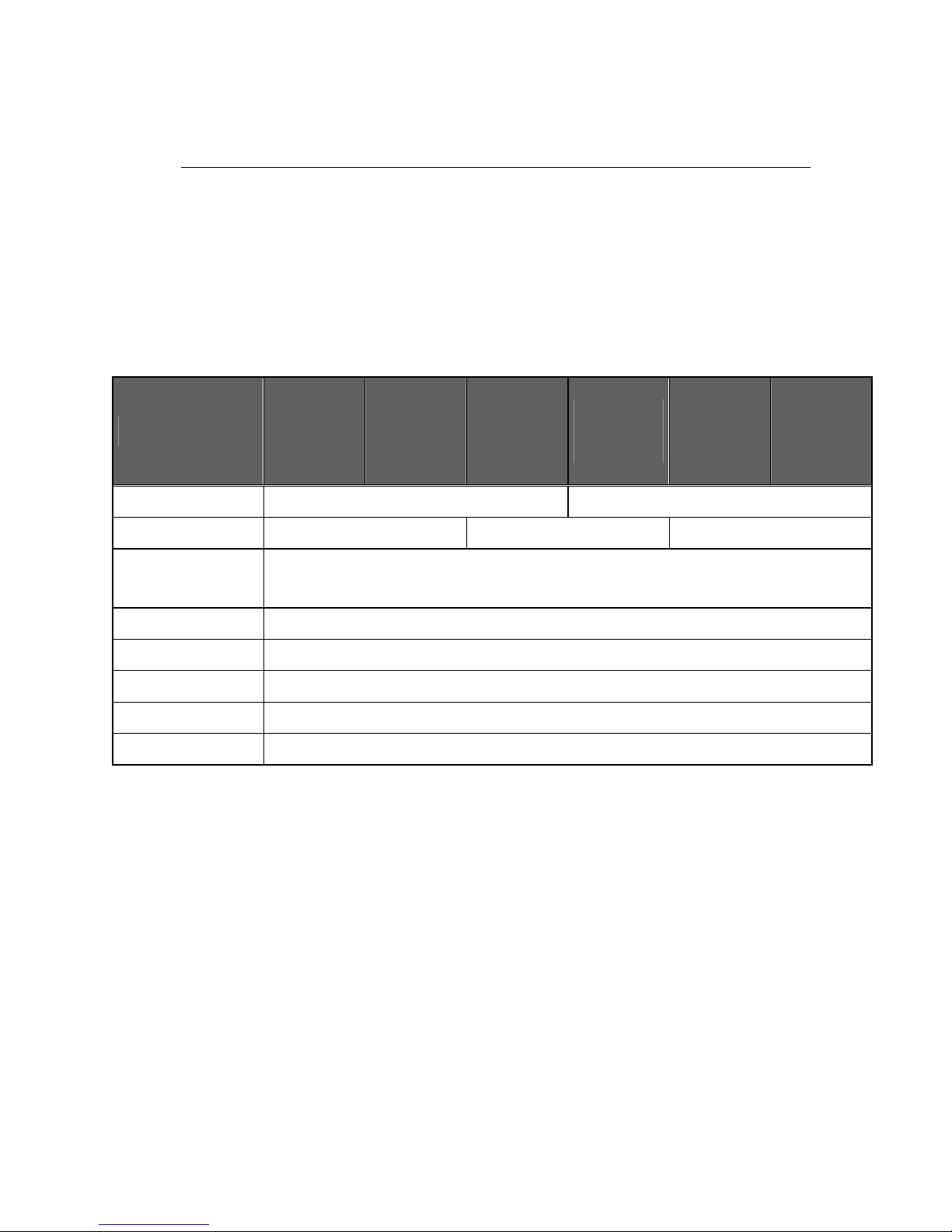
Table 3-1 Specifications
DESCRIPTION
STSHD253GI
STSHD085GJ
STSHD164GJ
ST160DM000
STSHD254GJ
ST250DM001
STSHD324HI
ST500DL001
STSHD324HJ
ST320DM001
ST500DM005
ST1000DL004
STSHD754JI
ST1000DM005
STSHD754JJ
Number of Disks
1 2
Number of R/W heads
1 2 4
Maximum Data
Transfer Rate(MB/s)
250
Track density (tpi)
245k
Interface
Serial ATA3.0Gbps
Actuator type
Rotary Voice Coil
Servo type
Embedded Sector Servo
Spindle speed
5,435/7,247 RPM class(Target RPM +/- 0.35%)
SPECIFICATIONS
Barracuda Product Manual Rev04
7
3.2 Physical Specifications
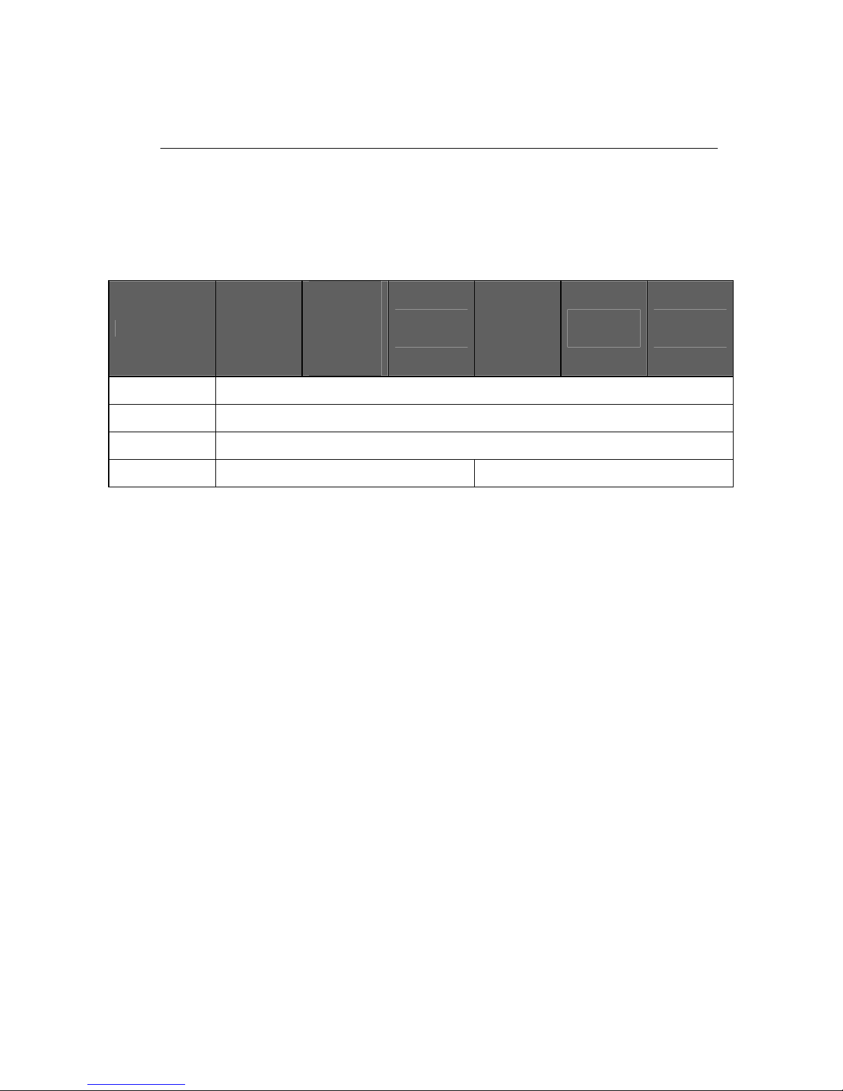
Table 3-2 Physical Specifications
DESCRIPTION
STSHD253GI
STSHD085GJ
STSHD164GJ
ST160DM000
STSHD254GJ
ST250DM001
STSHD324HI
ST500DL001
STSHD324HJ
ST320DM001
ST500DM005
ST1000DL004
STSHD754JI
ST1000DM005
STSHD754JJ
Length (mm) 147.00 Max
Width (mm)
101.60 ± 0.25
Height (mm) 26.10 Max
Weight (gram)
475 ± 10% 625 ± 10%

SPECIFICATIONS
Barracuda Product Manual Rev04
8
3.3 Logical Configurations
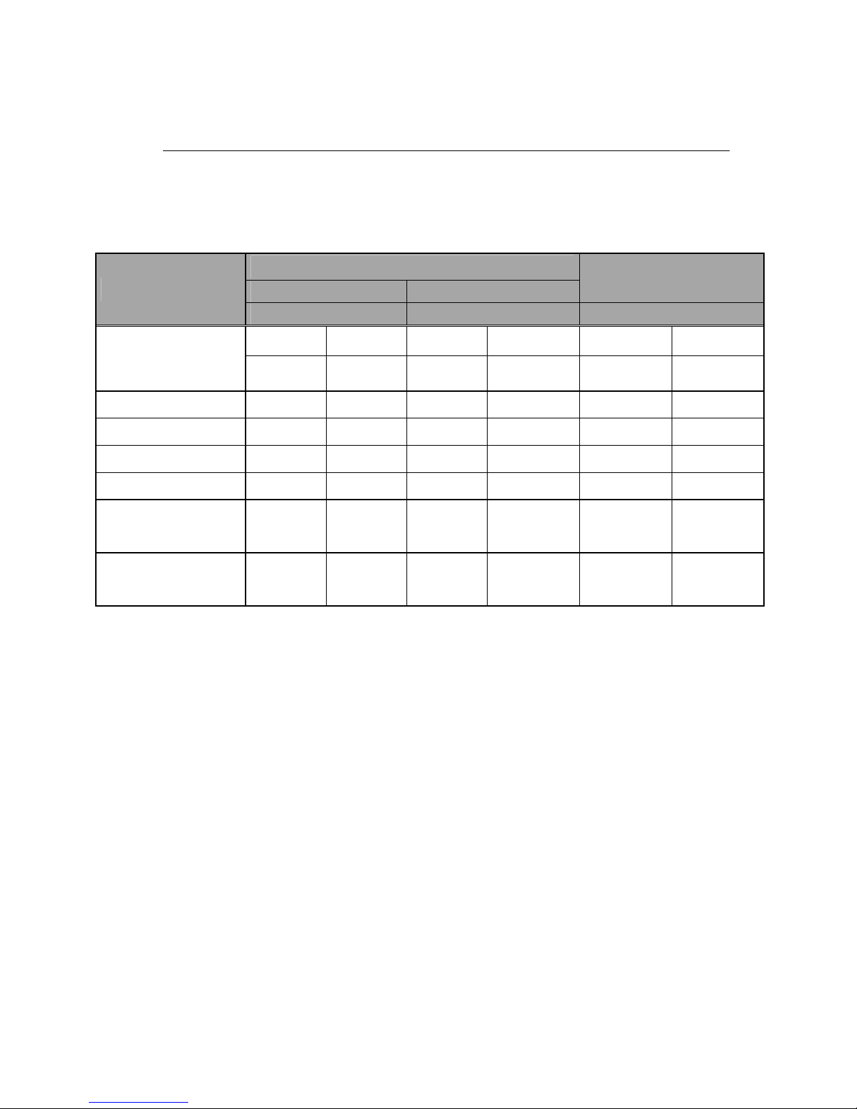
Table 3-3 Logical Configurations
DESCRIPTION
STSHD253GI
STSHD085GJ
STSHD164GJ
ST160DM000
STSHD254GJ
ST250DM001
STSHD324HI
ST500DL001
STSHD324HJ
ST320DM001
ST500DM005
ST1000DL004
STSHD754JI
ST1000DM005
STSHD754JJ
Default logical mode:
Number of cylinders
Number of heads / cylinders
Number of sectors / heads
16,383
16
63
Total Number of
logical sectors
488397168
156301488
312581808
312581808
4883971684
88397168
488397168
976773168
488397168
488397168
976773168
1953525168
1465149168
1953525168
1465149168
Capacity 250GB
80GB
160GB
160GB
250GB
250GB
320GB
500GB
320GB
320GB
500GB
1000GB
750GB
1000GB
750GB
* Maximum number of logical cylinders in CHS mode is 16,383.
Systems that incorporate more than 8.4GB per storage device must access the drive in LBA
addressing mode.

SPECIFICATIONS
Barracuda Product Manual Rev04
9
3.4 Performance Specifications
Table 3-4 Performance Specification
DESCRIPTION
STSHD253GI
STSHD085GJ
STSHD164GJ
ST160DM000
STSHD254GJ
ST250DM001
STSHD324HI
ST500DL001
STSHD324HJ
ST320DM001
ST500DM005
ST1000DL004
STSHD754JI
ST1000DM005
STSHD754JJ
Buffer size 16
8MB
8MB
16MB
8MB
16MB
16MB
8MB
16MB
32MB 32MB
Seek Time
(1)
(Performance
mode, RD, Typ./Max)
Average seek time
Track to track seek time
Full stroke seek time
8.9 / 10.5 ms
0.8 / 2.0 ms
18.0 / 20.0 ms
Seek Time
(1)
(Performance
mode, WR, Typ./Max)
Average seek time
Track to track seek time
Full stroke seek time
10.0 / 11.5 ms
1.0 / 3.0 ms
19.0 / 22.0 ms
Seek Time
(1)
(Quiet mode
(2)
,
Typ./Max)
Average seek time(RD)
Average seek time(WR)
12.0 / 14.0 ms
13.0 / 15.0 ms
Data Transfer Rate:
(Maximum)
buffer to/from media
host to/from buffer
250 MB/s
300 MB/s
Average latency
(3)
5.5 ms / 4.14ms
Rotational Speed
(4)
5,400 RPM 7,200 RPM 5,400 RPM 7,200 RPM 5,400 RPM 7,200 RPM

SPECIFICATIONS
Barracuda Product Manual Rev04
10
Power-on ready time
(Typical/Max)
(5)
7 / 20 8 /20 7 / 20 8 /20 10 /20 11 /20
Motor spin down time
(Typical/Max)
(5)
7 / 20 8 /20 7 / 20 8 /20 10 /20 11 /20
NOTES:
(1) Seek time is defined as the time from the receipt of a read, write or seek command until the
actuator has repositioned and settled on the desired track with the drive operating at nominal input
voltages, with nominal operating temperature, and without any external shock or vibration. Typical
value is defined as: typ = avg + 3*stdev/SQRT (N), where “avg” and “stdev” stand for the averaged
seek time and standard deviation of the seek time of N(N>40) samples, respectively. Average seek
time is determined by averaging the time to complete 1,000 seeks of random length. Maximum seek
time is determined as all the same procedure as in typical value except that the drives may operate at
all operating input voltage and all temperature ranges.
(2) Quiet mode is defined for AAM (automatic Acoustic Management) mode with minimum
performance.
(3) Average latency is the time required for the drive to rotate 1/2 of a revolution and on average is
incurred after a seek completion prior to reading or writing user data.
(4) Actual target RPM is close to 5,400/7,200 but can be a little bit different. However, spindle
control accuracy is within 0.35% of a pre-defined target RPM.
(5) Ready time is the time elapsed between the supply voltages reaching operating range and the
drive being ready to accept all commands. Maximum value is defined for all operating conditions
but the drive should be stored in the operating condition at least 8 hrs. The definition of the typical
value and maximum value are all the same as those of the seek time.
SPECIFICATIONS
Barracuda Product Manual Rev04
11
3.5 Power Requirements
Table 3-5 Power Requirements
(1)
Mode
Current (mA)
Power
(Watt)
+5 Volts
+12 Volts
1D / 2D
1D / 2D 1D / 2D
Spin-up (Typical)
5400rpm 7200rpm 5400rpm 7200rpm 5400rpm 7200rpm
1,900/2,000 2,000/2,200
Operating mode
(2)
Average Active idle
(3)
298 225/235 163 /223 285 / 385 3.80 / 4.60 4.80 / 6.20
Average Random seek
(4)
293 / 503 251/255 214 / 254 324 / 415 4.50 / 5.00 5.30 / 6.60
Average Read/Write
(5)
498 / 308 422/426 159 / 409 282 / 387 5.00 / 5.70 5.70 / 7.10
Average Standby
(6)
160/103
(*)/
160 / 93
(*)
116 / 104
(*)/
117 / 108
(*)
20 / 20
(*)
20 / 20
(*)
1.00 / 0.70(*) 1.00 / 0.70(*)
Average Sleep
(7)
160/103
(*)/
160 / 93
(*)
115 / 104
(*)
/
117 / 107
(*)
20 / 20
(*)
20 / 20
(*)
1.00 / 0.70
(*)
1.00 / 0.70
(*)
1) Operating conditions for the input voltage:
+5V5%, +12V10%. All the power requirements for the
different operating modes above are defined at
nominal input voltages, with nominal operating
temperature, and without any external shock or vibration. Current and power requirement
is defined as the averaged value for 40 ea after running the drives for 5 minutes at the
active idle status.
2) Operating mode: 40%,40%,and 20% duty for seek, RD/WR, and idle, respectively.
3) Active idle mode: spindle motor is spinning and heads are in random track location. Drive can
process the next command without delay.
4) Random seek mode : 30% duty cycle seek for random logical location.
5) Read/Write: Averaged RMS current or power for a continuous read or write of a consecutive 256
sectors on a single physical track with typical host command overhead. Read or write operation
should be done for the same logical location and thus the read or write duty should be less than 25%.
6) Standby: Microprocessor is powered, heads are parked, and spindle motor is stopped. Drive
responds to all commands. (*) stands for slumber mode.
7) Sleep: Microprocessor is powered for minimal block, heads are parked, spindle motor is stopped.
Drive responds only to hard/soft reset commands. (*) stands for slumber mode.

SPECIFICATIONS
Barracuda Product Manual Rev04
12
3.6 Environmental Specifications
Table 3-6 Environmental Specifications
DESCRIPTION
STSHD253GI
STSHD085GJ
STSHD164GJ
ST160DM000
STSHD254GJ
ST250DM001
STSHD324HI
ST500DL001
STSHD324HJ
ST320DM001
ST500DM005
ST1000DL004
STSHD754JI
ST1000DM005
STSHD754JJ
Ambient Temperature:
Operating
(1)
Non-operating
Max. gradient
(Temp/Humidity)
0 60C
-40 70C
20C/15%/hr
Relative Humidity
(non condensing)
Operation
Non-operation
Maximum wet bulb
temperature:
Operating
Non-operating
5~90 %
5~95 %
30 C
40 C
Altitude
(relative to sea level):
Operating
Non-operating
-1,000 10,000 feet
-1,000 40,000 feet
Vibration
Operating
Random
10-300Hz
Non-operating
Random
10-500Hz
1.08 Grms
3.80 Grms

SPECIFICATIONS
Barracuda Product Manual Rev04
13
Environmental Specifications (continued)
DESCRIPTION
STSHD253GI / STSHD085GJ / STSHD164GJ / ST160DM000
STSHD254GJ / ST250DM001 / STSHD324HI / ST500DL001
STSHD324HJ / ST320DM001 / ST500DM005 / ST1000DL004
STSHD754JI / ST1000DM005 / STSHD754JJ
Shock (1/2 sine pulse)
Operating
2.0 ms
Non-operating
2.0 ms
0.5 ms
10 ms
Rotational Shock
Operating
2.0 ms
Non-operating
2.0 ms
1.0 ms
70G
300G
200G
150G
2Krad/sec
20Krad/sec
25Krad/sec
Acoustic
Noise
Sound Power (typ/Max
n
)
5400rpm
STSHD253GI / STSHD085GJ
STSHD324HI / ST500DL001
ST1000DL004 / STSHD754JI
7200rpm
STSHD164GJ / ST160DM000
STSHD254GJ / ST250DM001
STSHD324HJ / ST320DM001
ST500DM005 / STSHD754JJ
ST1000DM005
Idle
Performance Seek
Quiet seek
2.2/2.5
2.7/2.8
2.8/2.9
2.5/2.7
2.8/2.9
2.9/3.1
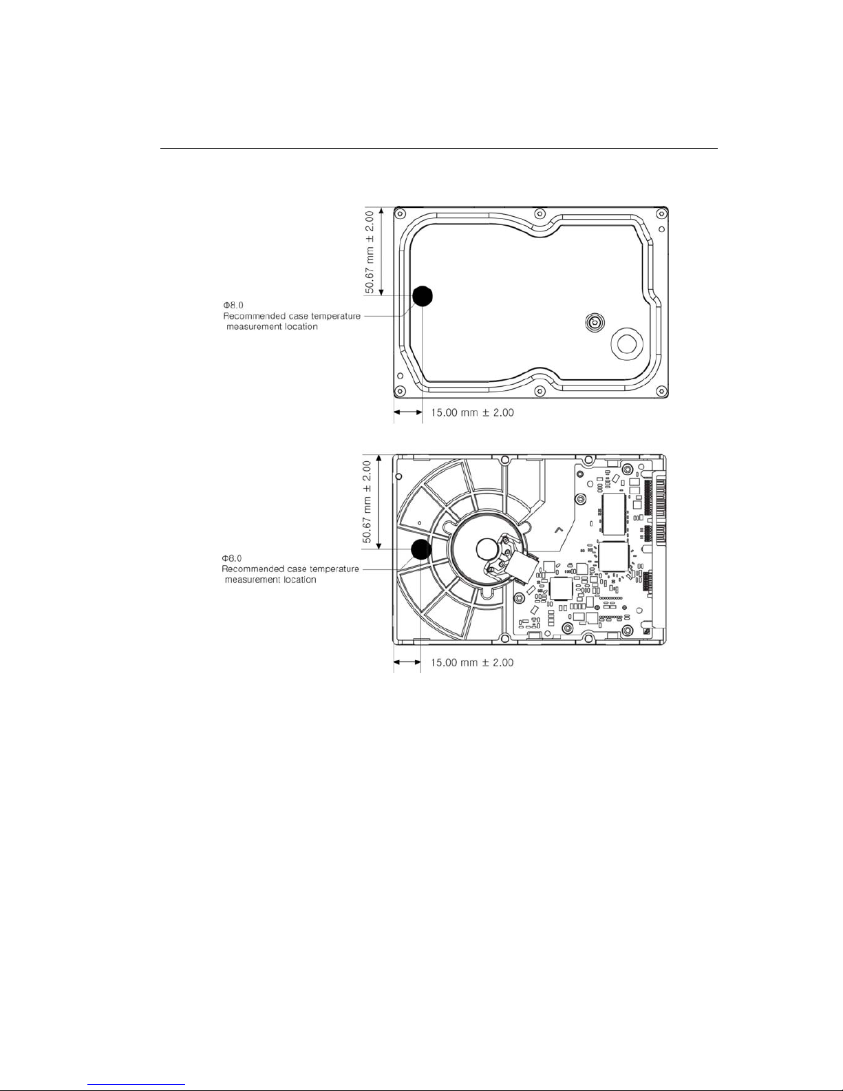
1) The drive case temperature should be lower than 69°C in an operating ambient condition.
SPECIFICATIONS
Barracuda Product Manual Rev04
14
< 1D >
SPECIFICATIONS
Barracuda Product Manual Rev04
15
<2D >
Figure 3-1 Case Temperature Measurement Point
SPECIFICATIONS
Barracuda Product Manual Rev04
16
3.7 Reliability Specifications
Table 3-7 Reliability Specifications
DESCRIPTION
STSHD253GI
STSHD085GJ
STSHD164GJ
ST160DM000
STSHD254GJ
ST250DM001
STSHD324HI
ST500DL001
STSHD324HJ
ST320DM001
ST500DM005
ST1000DL004
STSHD754JI
ST1000DM005
STSHD754JJ
Recoverable
Read Error:
<10 in 10
11
bits
Non-
Recoverable
Read Error:
<1 sector in 10
15
bits
MTBF (POH): 600,000 hours
MTTR (typical): 5 minutes
Start/Stop Cycle :
Ambient
50,000

Barracuda Product Manual Rev04
17
CHAPTER 4 INSTALLATION
This chapter describes how to unpack, mount, configure, and connect a Barracuda hard disk drive.
It also describes how to install the drive in systems.
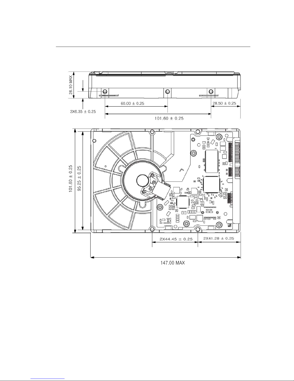
4.1 Space Requirements
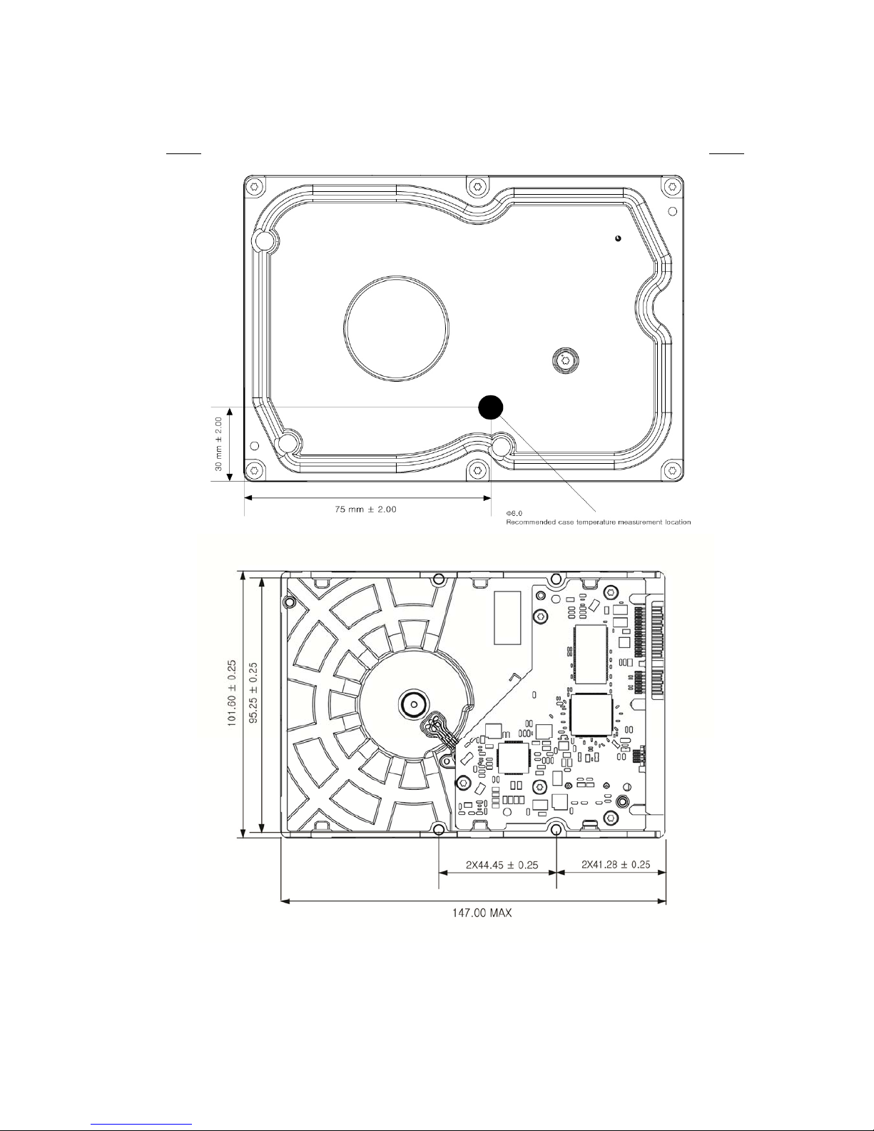
Figure 4-1 shows the external metric dimensions of the SATA HDD.
< 1D >
Barracuda Product Manual Rev04
18
< 2D >
Figure 4-1 Mechanical Dimension

Barracuda Product Manual Rev04
19
4.2 Unpacking Instructions
(1) Open the shipping container of Barracuda .
(2) Lift the packing assembly that contains the drive out of the shipping container.
(3) Remove the drive from the packing assembly. When you are ready to install the drive, remove it from
the ESD (Electro Static Discharge) protection bag. Take precautions to protect the drive from ESD
damage after removing it from the bag.
CAUTION: During shipment and handling, the anti-static ESD protection bag prevents
electronic component damage due to electrostatic discharge. To avoid accidental damage to
the drive, do not use a sharp instrument to open the ESD protection bag.
(4) Save the packing material for possible future use.
4.3 Mounting
Refer to your system manual for complete mounting details.
(1) Be sure that the system power is off.
(2) For mounting, use four 6-32 UNC screws.
CAUTION: To avoid stripping the mounting-hole threads, the maximum torque applied to
the screws must not exceed 8.0 Kg-cm (6.95 inch-pounds).
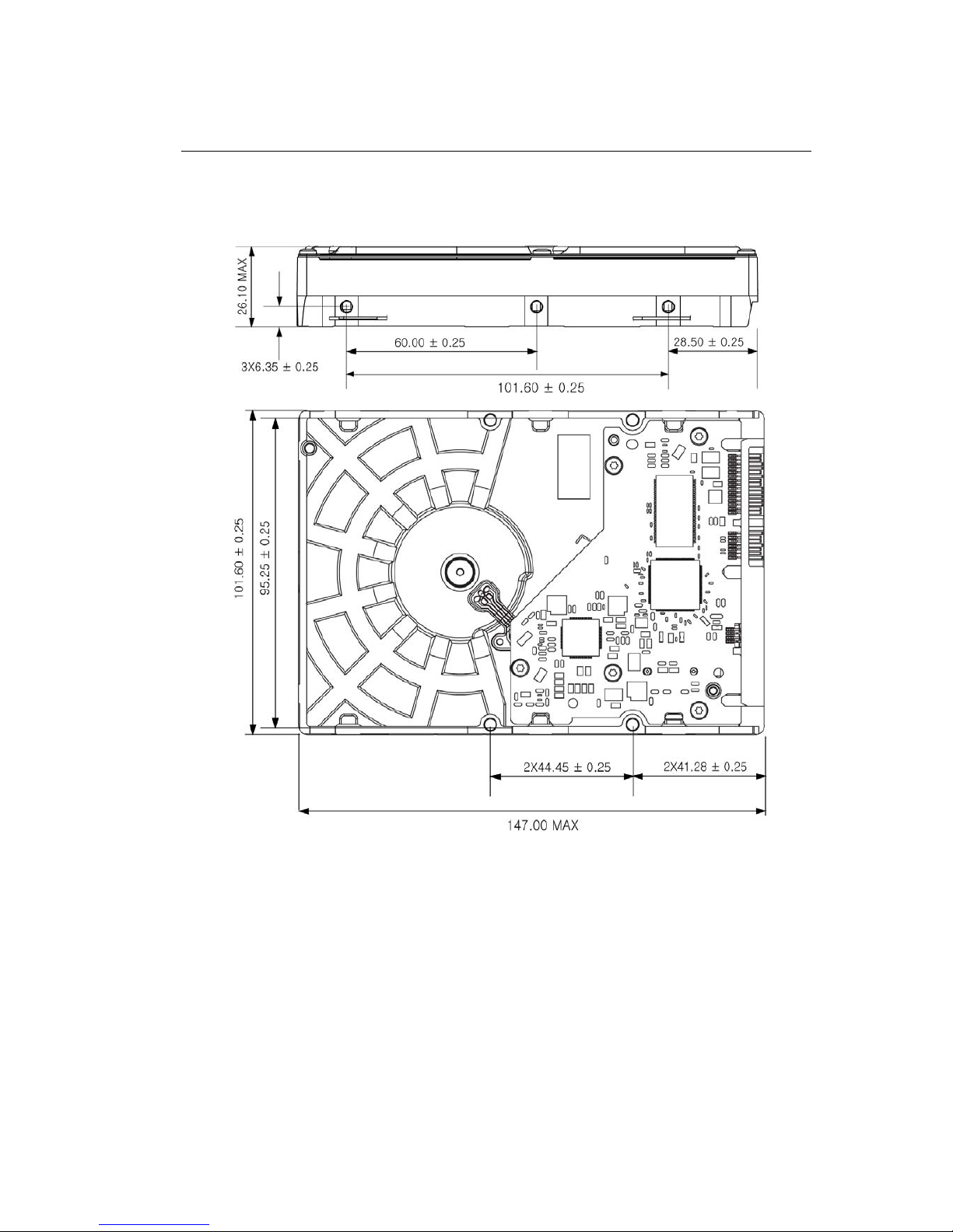
4.3.1 Orientation
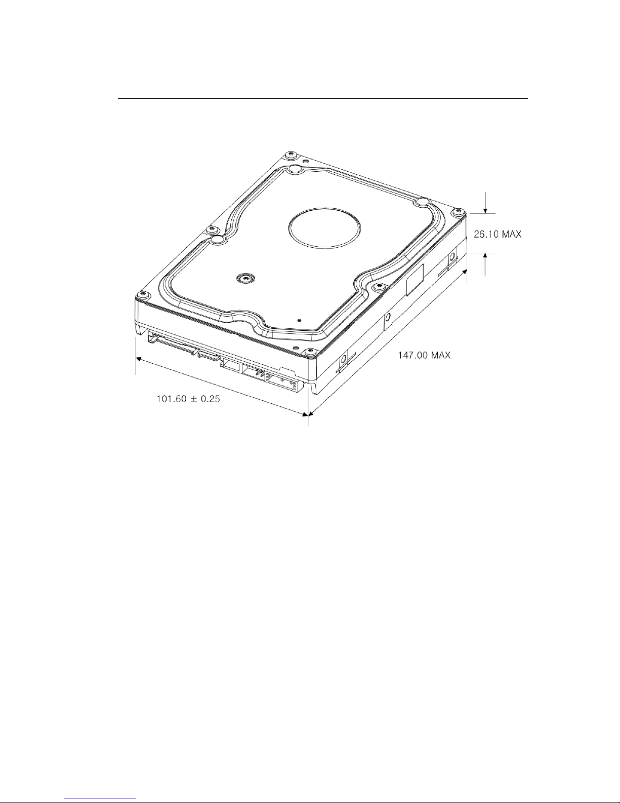
Figure 4-2 shows the physical dimensions and mounting holes located on each side of the drive.
The mounting holes on Barracuda hard disk drive allows the drive to be mounted in any direction.
Barracuda Product Manual Rev04
20
< 1D >
Barracuda Product Manual Rev04
21
< 2D >
Figure 4-2 Mounting Dimensions
Barracuda Product Manual Rev04
22
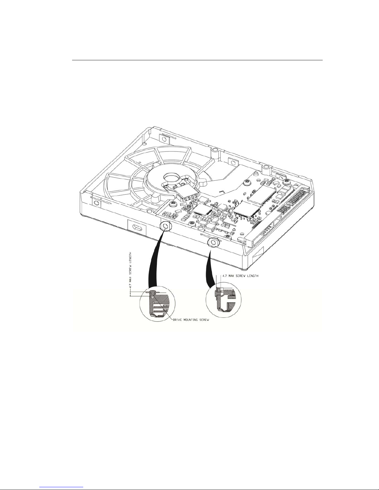
4.3.2 Clearance
The printed circuit board (PCB) is designed to be very close to the mounting holes. Do not exceed the
specified length for the mounting screw described in Figure 4-3. The specified screw length allows full use of
the mounting-hole threads, while avoiding damage or placing unwanted stress on the PCB.
< 1D >
 Loading...