

Page 1

OWNER’S MANUAL
SPINNING
®
STUDIO COMPUTER
Page 2

Page 3

CONTENTS
The Spinning® Studio Computer 4
What’s Inside 5
Computer Features 6
Pairing with the Cadence Sensor 7
Cadence Sensor Installation 9
Pairing with your Heart Rate Transmitter 13
Computer Mounting 14
Advanced Settings 16
Computer Care 18
Frequently Asked Questions 19
Certifications 21
Warranty Information and Customer Support 22
Page 4
©2015 Mad Dogg Athletics, Inc. All rights reserved. Spin®, Spinner®, Spinning®, Spin Fitness® and the Spinning logo ® are
registered trademarks that are owned by Mad Dogg Athletics, Inc.
4
THE SPINNING®
STUDIO COMPUTER
Thank you for purchasing the Spinning® Studio Computer. Heart rate
training is an essential aspect of the Spinning program, and this computer
will help you monitor your heart rate, cadence, time, distance and calories
burned on every ride. This owner’s manual will explain all of the key
features of this Computer, as well as take you through each step for
installing the Computer onto your Spinner® bike. Be sure to log on to
www.spinning.com for all the latest updates and information from Spinning.
Enjoy the ride!
Page 5
SPINNING® STUDIO COMPUTER OWNER’S MANUAL
www.spinning.com 800.847.SPIN (7746)
5
WHAT’S INSIDE
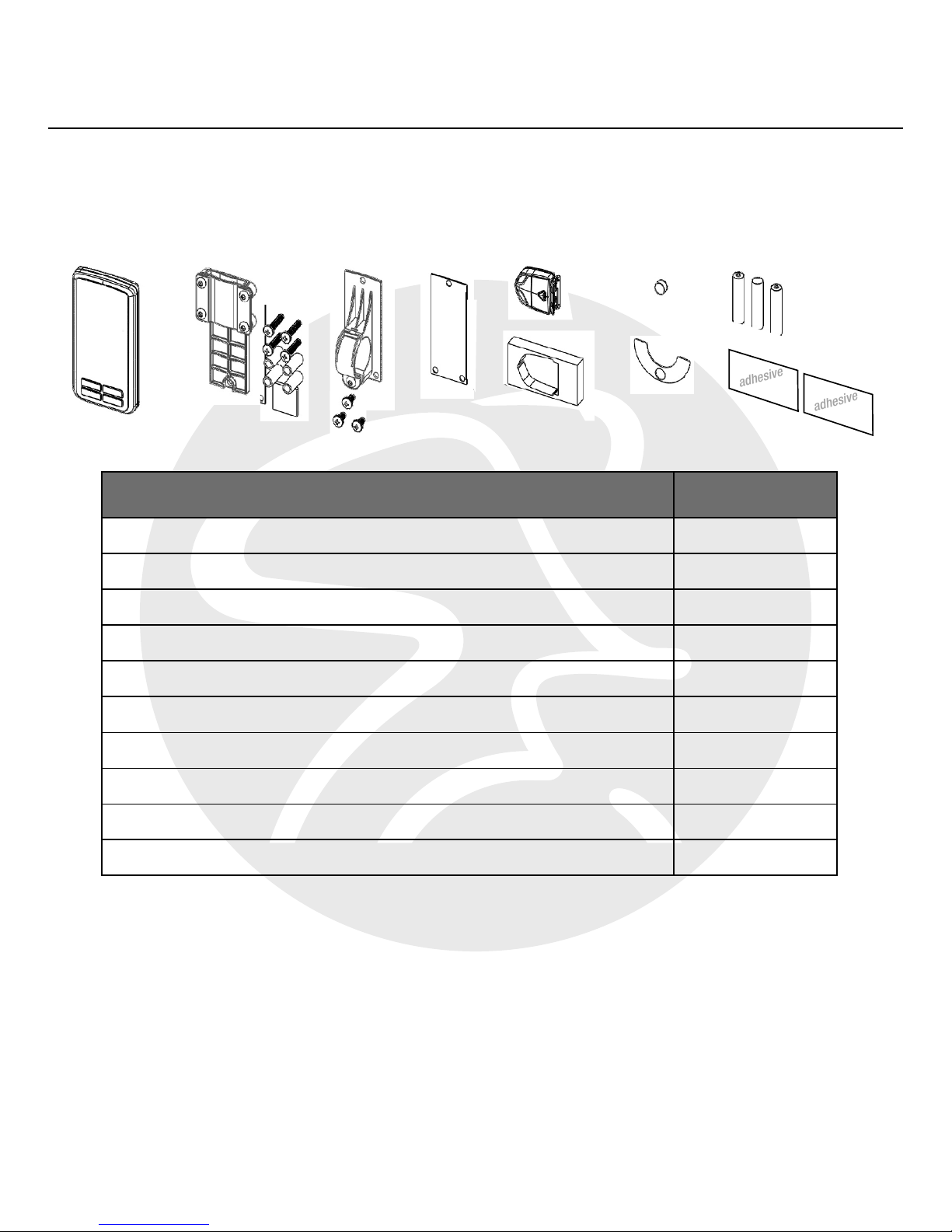
COMPONENT QUANTITY
1. Computer Console 1
2. Flat Mount Bracket with Four (4) Bolts 1
3. Ring Mount Bracket with Three (3) Bolts 1
4. Rubber Gasket Inlay 1
5. Cadence Sensor 1
6. Cadence Sensor Foam Holder 1
7. Magnet 1
8. Adhesive Magnet-Holding Shim 1
9. AAA Batteries for Computer Console 3
10. Double Stick Adhesive for Sensor Mounting 2
Tools Needed for Assembly:
1. Phillips Head Screwdriver
1. 2.
3. 4. 5.
6.
7.
8.
9.
10.
adhesive
adhesive
Page 6

©2015 Mad Dogg Athletics, Inc. All rights reserved. Spin®, Spinner®, Spinning®, Spin Fitness® and the Spinning logo ® are
registered trademarks that are owned by Mad Dogg Athletics, Inc.
ANT, ANT+ and the ANT+ logo are trademarks of Dynastream® Innovations Inc., a subsidiary of Garmin® Ltd.
6
COMPUTER FEATURES
Features:
• ANT+TM interoperable 2.4Ghz wireless technology
• Low power consumption for long battery life
• Code memory during battery displacement
• Large three line display; Cadence, Heart rate and Training data
• Bright LED backlight
• FCC ID: QSWASPDCS
• CE 1177 Certified
• ANT+ Certified
On-Screen Features:
• Cadence (measured in RPM) for current session
• Heart rate (measured in BPM) for current session
• Training data: Toggle the MODE button to see elapsed time,
equivalent distance traveled, and estimated calories burned
• Low battery indicator
General:
• ANT+ 2.4 GHz wireless radio to transmit data
• Batteries Required:
• Computer console uses 3 AAA batteries
• Cadence sensor uses 1 CR2032 lithium coin cell battery
• Life of batteries depends on usage
Page 7
SPINNING® STUDIO COMPUTER OWNER’S MANUAL
www.spinning.com 800.847.SPIN (7746)
7
PAIRING WITH THE
CADENCE SENSOR
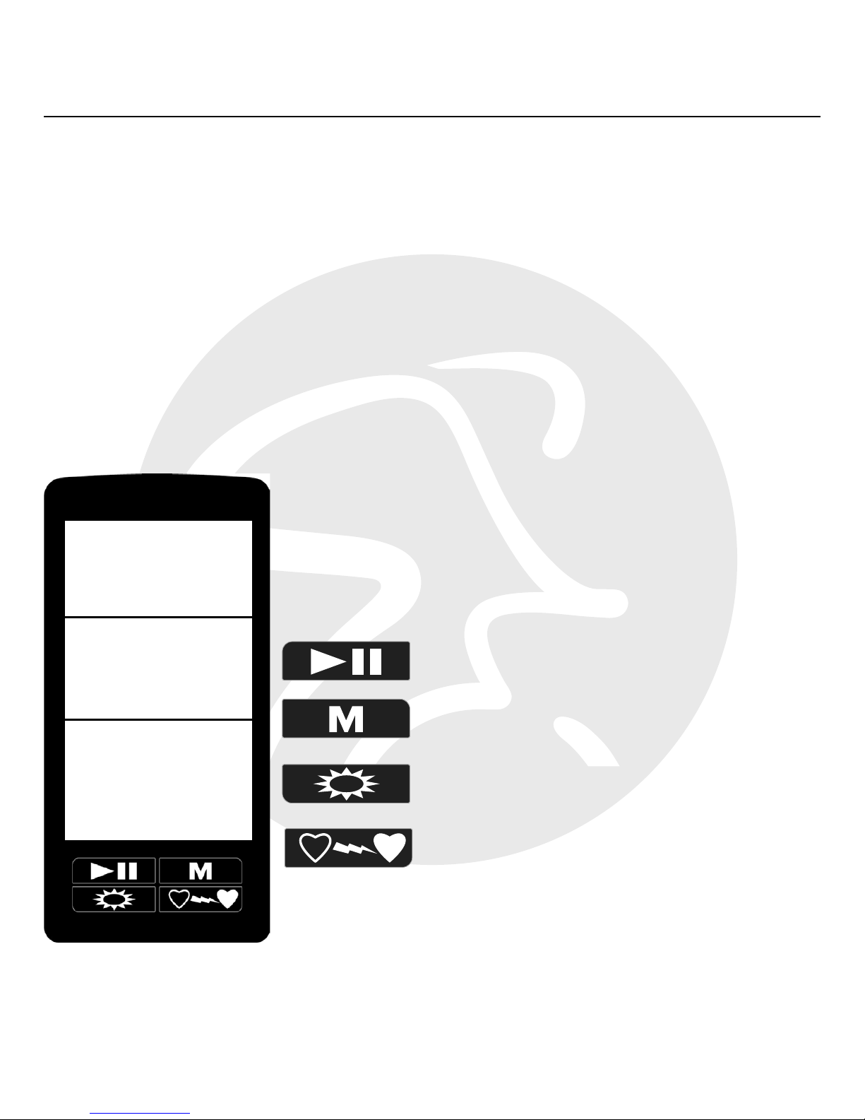
The Spinning® Studio Computer features a large, clear display and simple
four-button layout. It was designed to display your cadence and heart rate
information automatically. The following section will demonstrate how to
pair your cadence sensor to your Spinning Computer.
Start/Pause/Resume
MODE Button
Backlight
Pair Heart Rate Transmitter
cadence
heart rate
time
distance
calories
Page 8
©2015 Mad Dogg Athletics, Inc. All rights reserved. Spin®, Spinner®, Spinning®, Spin Fitness® and the Spinning logo ® are
registered trademarks that are owned by Mad Dogg Athletics, Inc.
8
To begin the process of pairing this Spinning® Computer with the cadence
sensor, follow the steps below:
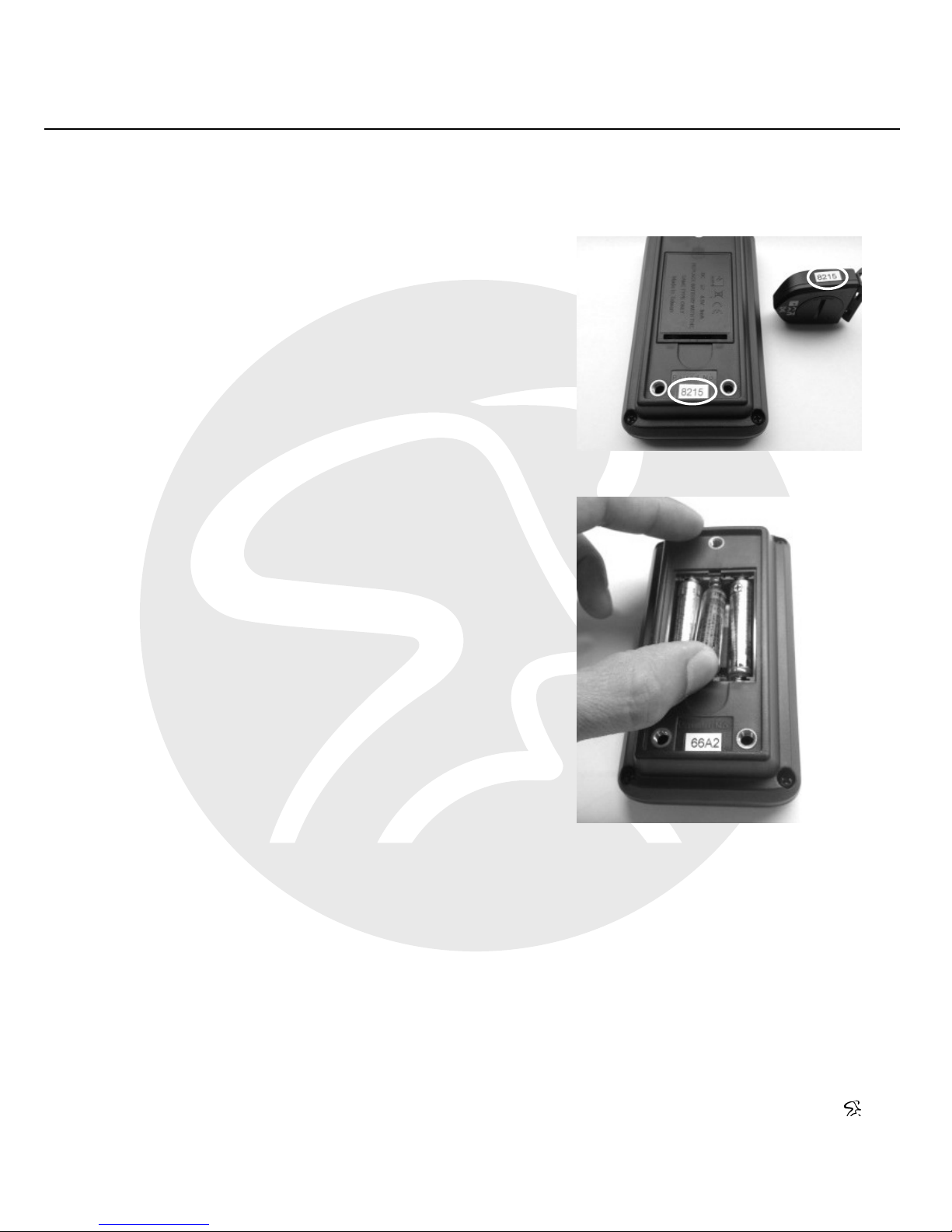
1. Check the four-digit code on the
back of the console and cadence
sensor (highlighted in Fig. 1) and
ensure that they match. Write
this code down in the event you
need to pair the sensor manually.
2. Remove the battery cap from
the console and install two of
the three AAA batteries into the
console.
3. Insert the third battery (as shown
in Fig. 2) while pressing and
holding the MODE button. The
display will show the four-digit
alphanumeric code found on
the back of the console and the
cadence sensor.
4. Press the Start/Pause/Resume button for automatic pairing with
your cadence sensor.
NOTE: If the console does not immediately pair with the cadence sensor,
please follow the instructions in the “Advanced Settings” section on page
16. The “Advance Settings” section also demonstrates how to adjust the
backlight time.
F. 2
F. 1
Page 9
SPINNING® STUDIO COMPUTER OWNER’S MANUAL
www.spinning.com 800.847.SPIN (7746)
9
CADENCE SENSOR INSTALLATION
The Spinning® Studio Computer will track your cadence (measured in
RPM) and distance. In order to track this information, you must first attach
the cadence sensor to the Spinner® bike. This requires five components
found in this kit; the cadence sensor, a foam holder, double-sided adhesive,
a magnet, and a magnet-holding shim. You also have two options for
mounting the sensor to the bike; outside the chain guard shroud or inside
the chain guard shroud. We give you two options for mounting the sensor
depending on the model of Spinner bike you are using, as some models
have dierent chain guard designs.
Mounting the Magnet:
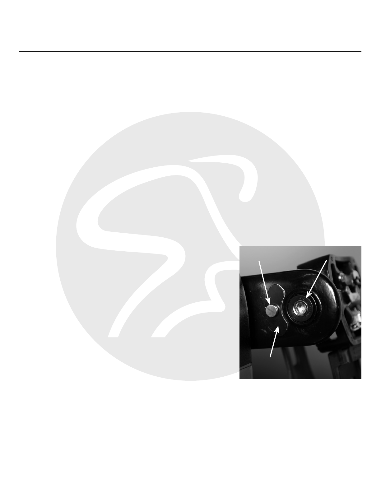
1. Examine the inside of the right crank
arm and ensure that it is clear of
obstructions. Wipe the inside of the
crank arm to remove any dust, grease
and grime.
2. Place the magnet on the inside of the
crank arm near (but not on top of) the
pedal spindle. Slowly rotate the crank
arm by hand to ensure that the magnet
does not collide with the chain guard.
3. Once the magnet is in place, peel the advisive cover o of the the
magnet-holding shim and place it on the inner surface of the right
crank arm around the magnet (as shown in Fig. 3).
Fig. 3
magnet
magnet-holding shim
pedal spindle
Page 10
©2015 Mad Dogg Athletics, Inc. All rights reserved. Spin®, Spinner®, Spinning®, Spin Fitness® and the Spinning logo ® are
registered trademarks that are owned by Mad Dogg Athletics, Inc.
10
NOTE: The cadence sensor must be within 10 cm (.4 inches) of the magnet
for pairing.
Sensor Installation, Outside the Chain Guard:
NOTE: This process is for Spinner® bike models with a flat underside.
1. Place with right crank arm at the very bottom of the pedal rotation.
2. Lock the flywheel and pedals by turning the resistance knob
clockwise.
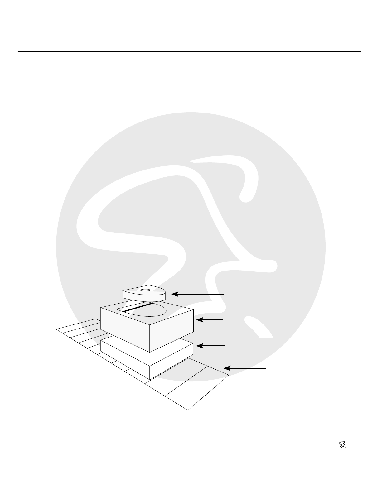
3. Place the cadence sensor inside the foam holder, as shown in Fig
4.
4. Ax the strip of double stick adhesive to the underside of the
cadence sensor and foam holder to cover the battery access cap
(Fig. 4).
cadence sensor
foam holder
double-sided adhesive
underside of
chain guard
shroud
F. 4
Page 11

SPINNING® STUDIO COMPUTER OWNER’S MANUAL
www.spinning.com 800.847.SPIN (7746)
11
5. Peel back the adhesive cover to expose the tape. Align it with the
magnet on the inside of the crank arm, as shown in Fig. 5.
6. Once the cadence sensor and the magnet are aligned, ax the
tape on the sensor to the underside of the shroud (Fig. 6) and test
synchronization.
NOTE: To test synchronization, first press the reset button on the sensor.
Rotate the bike pedals for at least ten rotations. A green light will flash after
each pass to confirm the synchronization between the sensor and magnet.
Sensor Installation, Inside the Chain Guard:
NOTE: This process is for Spinner® bike models with a rounded chain
guard and non-flat underside.
1. Lock the flywheel and pedals by turning the resistance knob
clockwise.
F. 6F. 5
Page 12
©2015 Mad Dogg Athletics, Inc. All rights reserved. Spin®, Spinner®, Spinning®, Spin Fitness® and the Spinning logo ® are
registered trademarks that are owned by Mad Dogg Athletics, Inc.
12
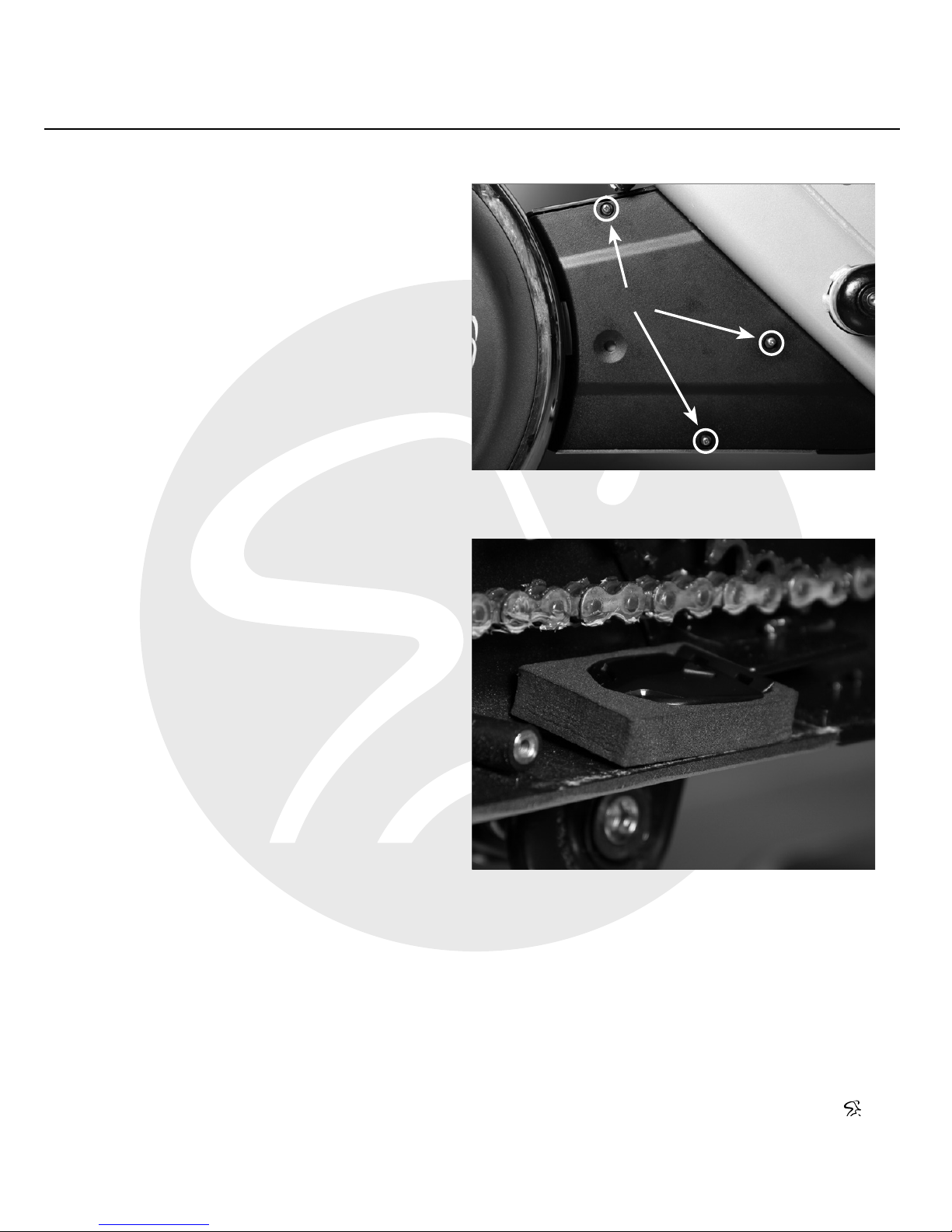
2. Remove the inner chain guard
shoud by removing the three
screws (highlighted in Fig. 7).
3. Place the cadence sensor
inside the foam holder (Fig. 4).
4. Ax the strip of double stick
adhesive to the underside of
the cadence sensor and foam
holder to cover the battery
access cap.
5. Mount the cadence sensor
and foam holder to the inside
of the shroud, as shown in
Fig. 8. It should be within 10
cm (.4 inches) of the magnet
on the crank arm.
6. Reinstall the chain
guard shroud and test
synchronization.
NOTE: To test synchronization, first press the reset button on the sensor.
Rotate the bike pedals for at least ten rotations. A green light will flash after
each pass to confirm the synchronization between the sensor and magnet.
F. 7
F. 8
screw locations
Page 13

SPINNING® STUDIO COMPUTER OWNER’S MANUAL
www.spinning.com 800.847.SPIN (7746)
13
To begin the simple process of pairing the Computer with your heart rate
transmitter, follow the steps below:
1. Press the MODE button to advance out of the setup screen. The
heart rate information will appear in the middle of the display.
2. Press the Pair Heart Rate Transmitter button for automatic pairing
with your heart rate transmitter. The screen will display an ANT+
symbol to signal pairing. Please remember that the heart rate
transmitter must be within 30 cm (12 inches) of the console for
pairing.
Start pedaling, and the display will give you information on heart rate,
cadence, time, distance and calories. Once you have successfully paired
the console with your heart rate transmitter, you are ready to mount the
console to your bike, which is explained on the next page.
If you have any questions regarding this process or are having diculty
pairing your heart rate transmitter to the computer, please refer to the
“Frequently Asked Questions” section on page 19.
PAIRING WITH YOUR
HEART RATE TRANSMITTER
Page 14
©2015 Mad Dogg Athletics, Inc. All rights reserved. Spin®, Spinner®, Spinning®, Spin Fitness® and the Spinning logo ® are
registered trademarks that are owned by Mad Dogg Athletics, Inc.
14
COMPUTER MOUNTING
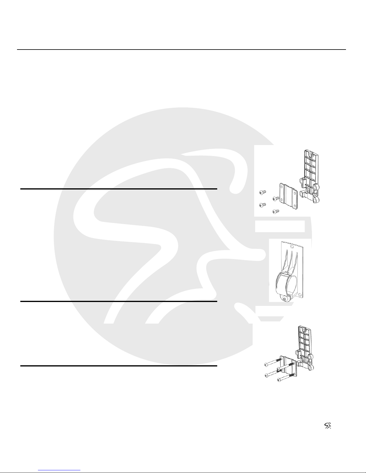
The Spinning® Studio Computer was designed to fit all commercial
Spinner® bikes. Use the brackets listed below based on the Spinner bike
you are using. Instructions for mounting the console appear on the next
page.
c áÖK=N=
c áÖK=O=
c áÖK=P=
The following bikes can have the Spinning Studio Computer
installed using the flat mount bracket as shown in Fig. 9.
The following bikes can have the Spinning Studio Computer
installed using the ring mount bracket as shown in Fig. 10.
The following bikes can have the Spinning Studio Computer
installed using the flat mount bracket as shown in Fig. 11.
Manufacturer
SKU
7170
7180
7190
7160
7230
7240
Spinner
Bike Name
Spinner NXT
Spinner NXT
Spinner BLADE
Spinner PRO+
Spinner NXT Black Belt
TM
Spinner BLADE Belt
Manufacturer
SKU
7150
Spinner
Bike Name
Spinner VELO
Manufacturer
SKU
7090
7000
7070
7080
Spinner
Bike Name
Spinner NXT
Spinner NXT
Spinner PRO
Spinner ELITE
F. 9
F. 10
F. 11
NOTE: The manufacturer SKU can be found on the bike serial number sticker.
Page 15
SPINNING® STUDIO COMPUTER OWNER’S MANUAL
www.spinning.com 800.847.SPIN (7746)
15
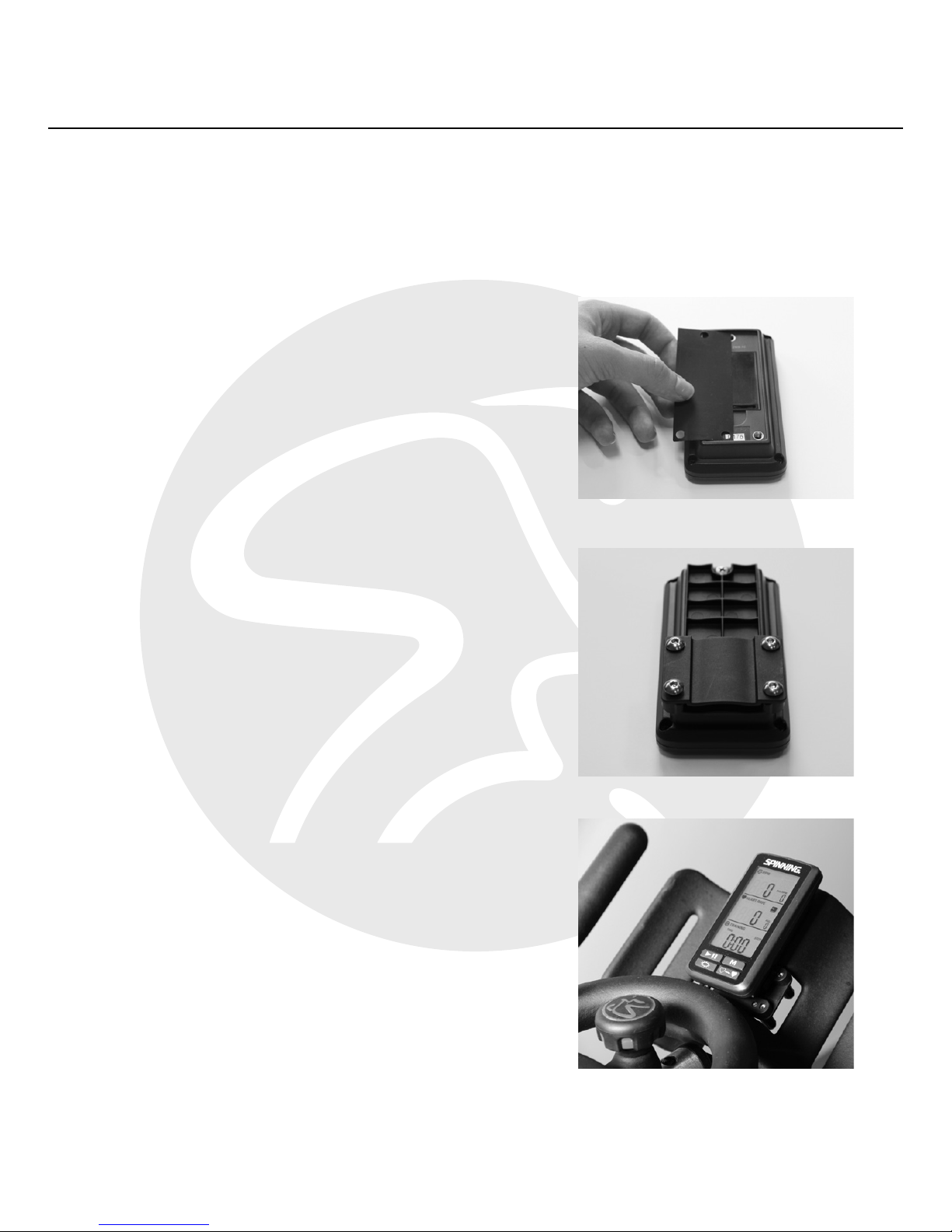
1. After successfully pairing with
the cadence sensor and heart
rate transmitter, place the rubber
gasket inlay behind the console,
as shown in Fig. 12.
2. Select the ring or flat bracket
(depending on Spinner bike model
you are using) and secure it to the
back of the console with the three
or four Phillips head screws (the
flat mount bracket is shown in Fig.
13).
3. Mount the console and bracket
assembly just above or on the
center loop of the handlebars
(depending on the Spinner bike
model you are using) and secure it
with the bolts (mounting above the
loop is shown in Fig. 14). This is the
ideal location for a clear view of
the console, and it will not interfere
with any of the hand positions.
F. 12
F. 13
F. 14
To mount this Spinning® Computer to your Spinner® bike, please follow
the steps below. Please ensure that the console is pairing properly with
your cadence sensor and heart rate transmitter before mounting it to
the bike.
Page 16
©2015 Mad Dogg Athletics, Inc. All rights reserved. Spin®, Spinner®, Spinning®, Spin Fitness® and the Spinning logo ® are
registered trademarks that are owned by Mad Dogg Athletics, Inc.
16
S
LS
M
M
M M M
M
E3a-1 *1
E4a
E5a
M
Flow Chart A
ADVANCED SETTINGS
M S M M M
E1
E2a
E3a
E3a-1 *1
E4a
E5a
M
Flow Chart A
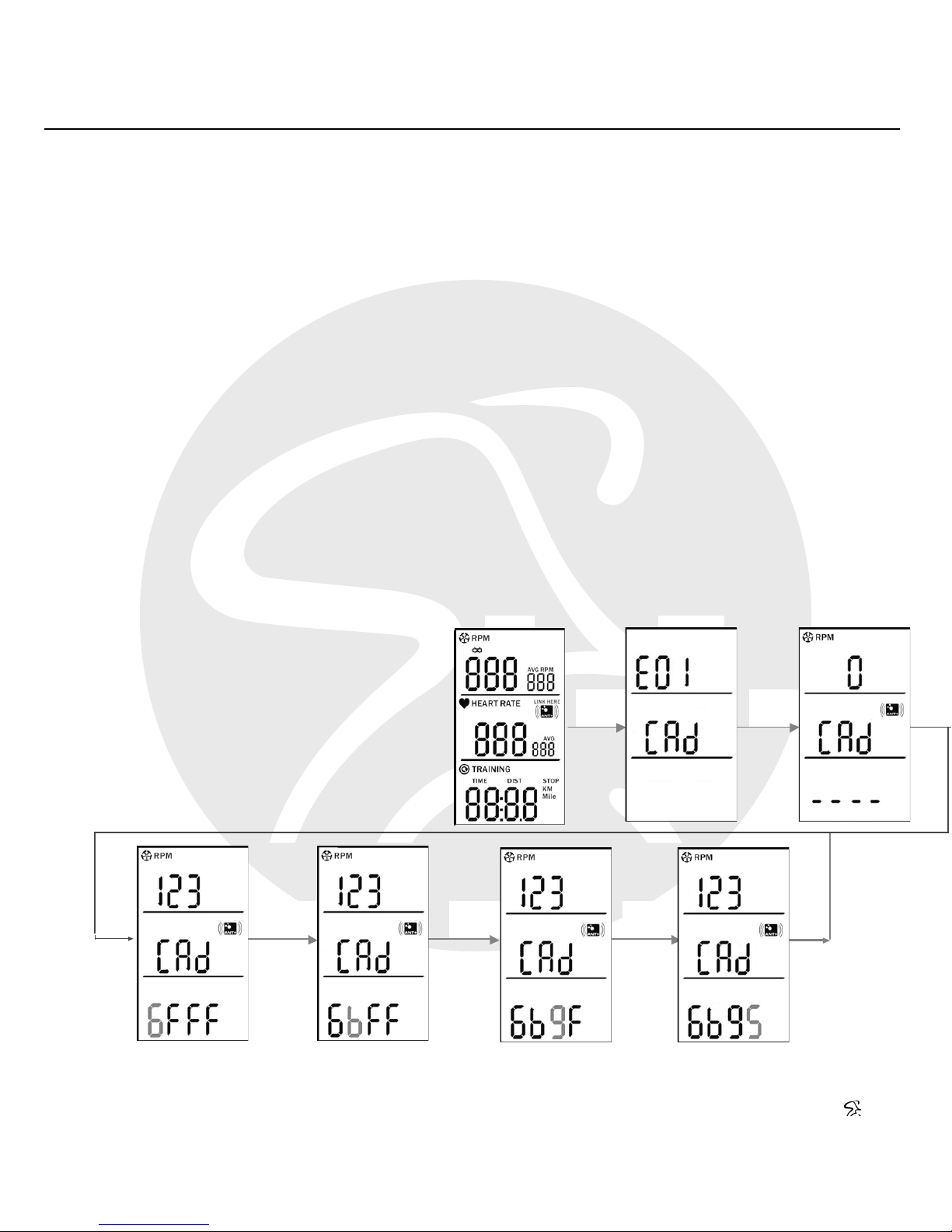
To manually pair the console with the cadence sensor, please follow the
instructions below:
1. Press and hold the Start/Pause/Resume button until the bottom of
the screen starts flashing.
2. To enter the four-digit code on the sensor, use the Backlight
button to scroll up in the code setting and the Pair Heart Rate
Transmitter button to advance to the next number.
3. Press the MODE button to the return to the cadence information
screen.
Page 17
SPINNING® STUDIO COMPUTER OWNER’S MANUAL
www.spinning.com 800.847.SPIN (7746)
17
S M M
E3a-1 *1
E4a
E5a
M
Flow Chart A
Flow Chart Key:
S: Start/Pause/Resume Button
LS: Long press Start/Pause/Resume Button
M: MODE Button
LM: Long press MODE Button
B: Backlight Button (increase number in code setting)
P: Pair Heart Rate Transmitter (decrease number in code setting)
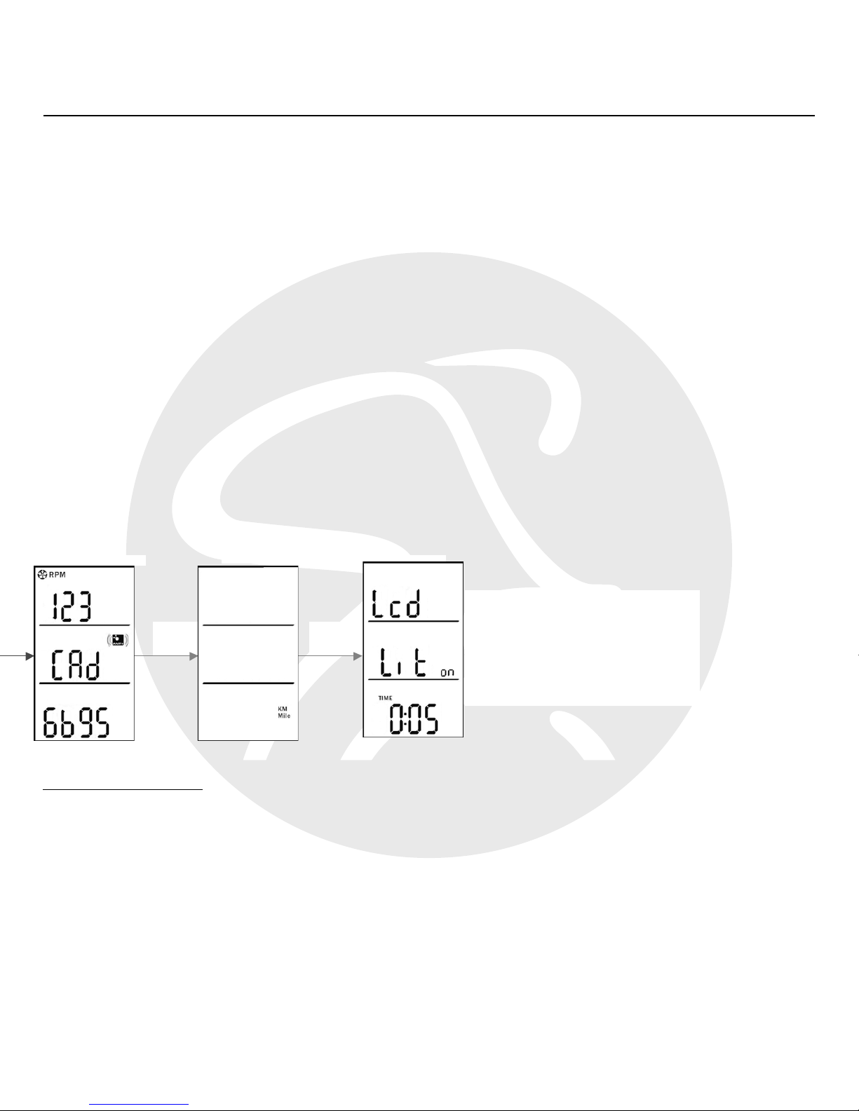
To adjust the amount of time that the backlight remains on after use, please
follow the instructions below:
1. From the cadence information screen, press the MODE button
twice.
2. The LCD display will appear with a time on the bottom. Increase
the time using the Backlight button, or decrease it using the Pair
Heart Rate Transmitter button.
NOTE: Increasing the amount of time the backlight stays on will diminish
battery life. The default setting on for the backlight time on the computer is
5 seconds.
Page 18

©2015 Mad Dogg Athletics, Inc. All rights reserved. Spin®, Spinner®, Spinning®, Spin Fitness® and the Spinning logo ® are
registered trademarks that are owned by Mad Dogg Athletics, Inc.
18
COMPUTER CARE
Spinning® strongly recommends performing regular maintenance to ensure
the computer is working at its best for years to come. The recommended
maintenance procedures are listed below:
Daily:
• Wipe down the computer with a soft cloth after each use.
• Dilute a non-toxic cleaner like Simple Green® with water in a 30:1
water-to-cleaner ratio. Spray the solution onto a soft cloth, then
wipe the computer console.
• Never spray directly onto the computer console. Never use
abrasive cloths or oil, ammonia or alcohol-based cleaners.
Weekly:
• Inspect each console for loose parts, bolts and nuts. Adjust and
tighten loose points as needed.
• Remove any consoles that are not properly mounted or at risk of
coming loose.
Monthly:
• Inspect all areas for proper adjustments.
• Inspect all parts for damage which could require possible
replacement.
• Inspect mounting of the cadence sensor and magnet to ensure it is
intact and working properly.
• A “low battery” indicator will display when batteries need
replacing. Replace the batteries in the console with 3 high-quality
AAA alkaline batteries from brands like Panasonic®, Duracell® and
Energizer®.
Page 19

SPINNING® STUDIO COMPUTER OWNER’S MANUAL
www.spinning.com 800.847.SPIN (7746)
19
FREQUENTLY ASKED QUESTIONS
Which heart rate transmitters will work with the Spinning® Studio
Computer?
Any ANT+ compatible heart rate transmitter will work with this Spinning
Computer, and pairing to an ANT+ transmitter will prevent any heart rate
“crosstalk”. Also, any analog 5.3 KHz heart rate transmitter such as Polar®
Wearlink
will pair with the this Computer. We recommend the Spinning
Connect heart rate transmitter, as it will pair with this computer as well as
BLE-receiving smart phones.
What if the computer is not picking up my heart rate?
We recommend following these steps to connect your heart rate
transmitter with the Computer:
• Make sure that the transmitter fits snuggly at the bottom of your
ribcage and that the sensors are slightly moistened.
• The battery in the transmitter may be low. Try another strap or
replace the battery/batteries inside your heart rate transmitter to
facilitate pairing.
• Try using the Pair Heart Rate Transmitter button in the lower left
for manual pairing with the Computer. For ANT+ chest straps, the
displayed code will be alphanumeric. For analog transmitters, the
code will be 4-digits and displayed as 0000.
• Check your distance from the Computer during syncing. Make sure
you are 30 cm (12 inches) or closer to the computer.
Page 20

©2015 Mad Dogg Athletics, Inc. All rights reserved. Spin®, Spinner®, Spinning®, Spin Fitness® and the Spinning logo ® are
registered trademarks that are owned by Mad Dogg Athletics, Inc.
20
What if I am picking up another riders heart rate?
If bikes and riders are close enough together while wearing analog heart
rate transmitters, it is possible to have “crosstalk” wherein the heart rate
signal from another rider is shown on an adjacent console. Using ANT+
compatible transmitters will prevent this problem, but if this problem
persists, you can also try moving the bikes further apart to prevent this
“crosstalk”. The initial close proximity heart rate pairing to each individual
computer is an important step to prevent “crosstalk”.
What batteries does the computer console and cadence sensor take?
The computer console requires three AAA batteries. The cadence sensor
requires one CR2032 lithium coin cell battery.
What is the best way to preserve battery life on the computer?
Excessive use of the backlight will diminish battery life, so we recommend
keeping the backlight o to preserve battery life.
How do I clear the display after a ride?
The display will turn o automatically after 5 minutes of inactivity. To reset
or clear your training data during or after a ride, press and hold the Start/
Pause/Resume button for 10 seconds, and the data will reset.
Page 21

SPINNING® STUDIO COMPUTER OWNER’S MANUAL
www.spinning.com 800.847.SPIN (7746)
21
CERTIFICATIONS
Federal Communication Commission Interference Statement
This device complies with Part 15 of the FCC Rules. Operation is subject the
following two conditions: (1) this device may not cause harmful interference,
and (2) this device must accept any interference received, including
interference that may cause undesired operation.
Changes or modifications not expressly approved by Spinning® could void
the user’s authority to operate the equipment.
FCC ID: QSWASPDCS
EU Declaration of Conformity
This device complies with the essential requirements of the R&TTE
Directive 1999/5/EC.
ANT+
This console is ANT+ certified.
1177
Page 22

©2015 Mad Dogg Athletics, Inc. All rights reserved. Spin®, Spinner®, Spinning®, Spin Fitness® and the Spinning logo ® are
registered trademarks that are owned by Mad Dogg Athletics, Inc.
22
WARRANTY INFORMATION AND
CUSTOMER SUPPORT
Warranty:
The Spinning® Studio Computer has a one-year warranty on the console
and sensor. This warranty excludes batteries and battery replacement.
Customer Support:
If you have any questions about this computer or any items are in need
replacement, please contact our customer service departments, which are
listed below:
For customers within North and
South America and Asia Pacific,
please contact:
MAD DOGG ATHLETICS, INC.
2111 Narcissus Court
Venice, CA 90291 U.S.A
Toll-free: 1.800.847.7746
Dialing outside U.S.:
1.310.823.7008
Fax: 1.310.823.7408
[email protected]
Hours: 6:00 AM–5:00 PM PST
For customers within Europe, the
Middle East and Africa, please
contact:
MAD DOGG ATHLETICS EUROPE
Industrieweg 20A
3144 CH Maassluis
The Netherlands
Phone: +31.1059.04508
Fax: +31.1059.00054
[email protected]
Hours: 9:00 AM–5:30 PM CET
Page 23
SPINNING® STUDIO COMPUTER OWNER’S MANUAL
www.spinning.com 800.847.SPIN (7746)
23
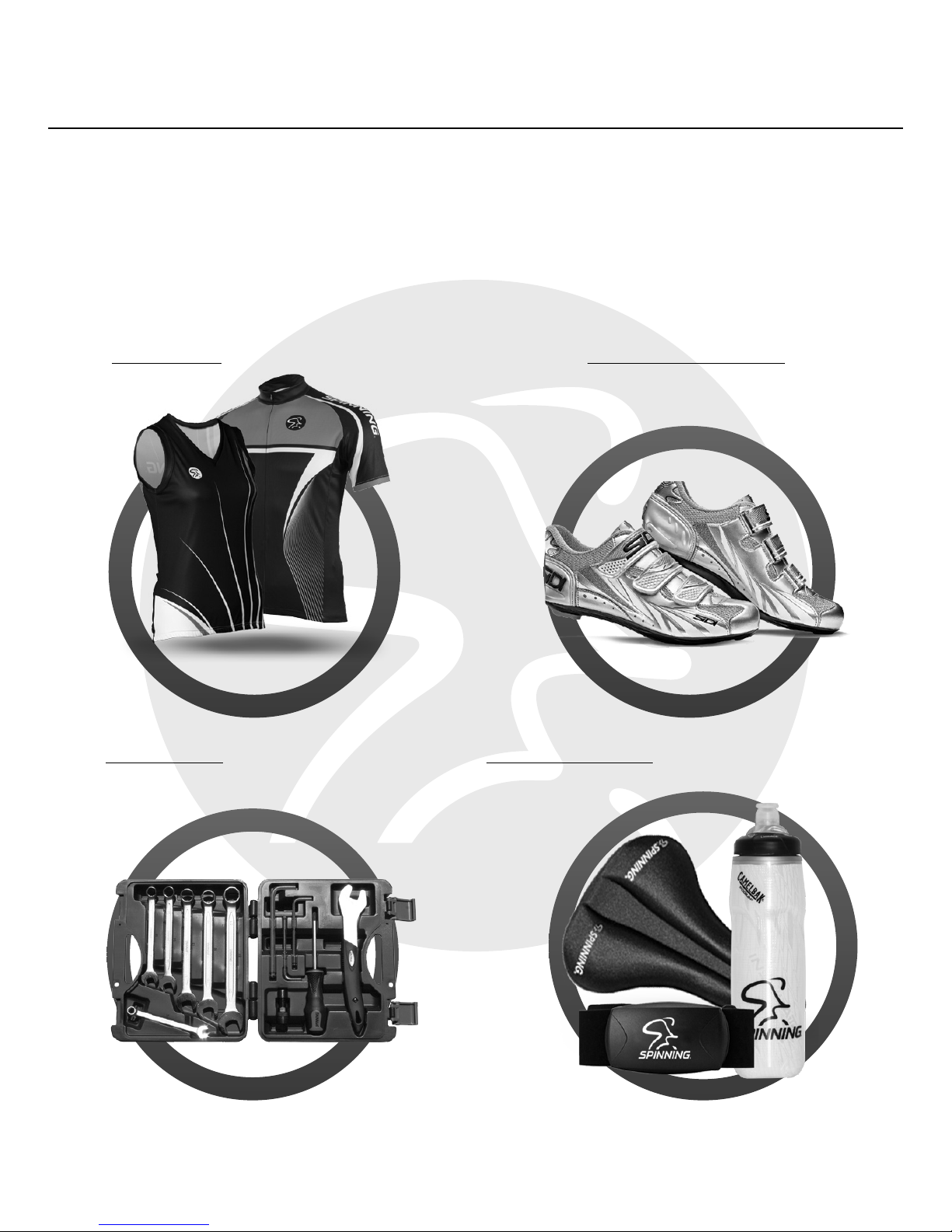
BE SURE TO VISIT SPINNING.COM
FOR ALL YOUR SPINNING® NEEDS.
Apparel Cycling Shoes
Tool Kits Accessories
Page 24

MAD DOGG ATHLETICS, INC.
2111 Narcissus Court
Venice, CA 90291 U.S.A
Toll-free: 1.800.847.7746
Dialing outside U.S.:
1.310.823.7008
Fax: 1.310.823.7408
www.spinning.com
MAD DOGG ATHLETICS EUROPE
Industrieweg 20A
3144 CH Maassluis
The Netherlands
Phone: +31.1059.04508
Fax: +31.1059.00054
7944REV2
 Loading...