

Spinning BIO, BIO HR Owner's Manual
OWNER’S MANUAL
BIO™
COMPUTER
BIO HR™
COMPUTER
BIO™ and BIO HR™
• Computer Monitor/Display
• (2) Triple AAA Batteries for Display
• Cadence Sensor–Includes CR2032 Battery
• (2) Zip ties for Cadence Sensor
• Round Handlebar Mount for Monitor
• Oval Handlebar Mount for Monitor
• Rubber Insert for Oval Mount
• Handlebar Mount Screw/Nut
For BIO HR™ only
• Heart Rate Strap–Includes CR2032 Battery
PARTS LIST
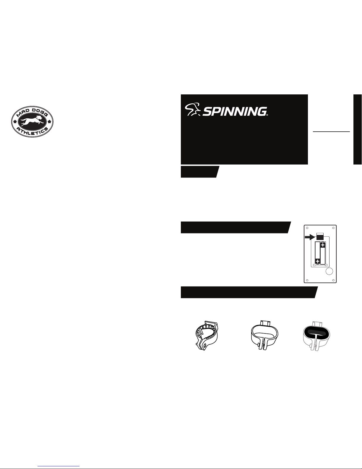
INSTALLING BATTERIES IN COMPUTER DISPLAY
INSTALLING MOUTING BRACKET ON BICYCLE HANDLEBARS
© SPIN®, Spinning®, Spinner® and the Spinning logo are registered trademarks of Mad Dogg Athletics, Inc.
• Open the battery cover by exing the tab at the top as shown.
• Insert 2 Triple AAA batteries as shown. Make sure each
battery is installed with correct +/- polarity.
• Snap battery cover back into place.
If the display is only partially visible, please reset the device by
removing the batteries for at least 15 seconds and then reinstall
them. Note that previous exercise data will be lost when
batteries are removed.
• Mounting adapters for all Spinner® bikes are included with the computer.
• Select the proper mount for your bike from the list below.
• Stretch mount over handle bar in desired location and secure with
provided screw and nut. The screw and nut work with either mount.
Round adapter
For Sport, FIT, Pace, Ascent, and
Sprint Spinner® Bikes
Oval Adapter
For Edge, Aero, and Pro
Spinner Bikes
Rubber Insert
For NXT, NXT SR, and Blade
Spinner Bikes
MAD DOGG ATHLETICS, INC.
2111 Narcissus Cour t • Venice, CA 90291 • USA
TEL 1 800 847 SPIN (7 746) • TEL 1 310 823 7008 • FA X 1 310 823 7408
MAD DOGG ATHLETI CS EUROP E, BV
Indus triewe g 20A • 3144 C H Maassl uis • The Ne therla nds
TEL +31 (0) 1 0 590 4508 • FA X +31 (0) 10 590 005 4
MAD DOGG ATHLETI CS SRL
Via G. Fe rraris 1 2 • 56121 - Pisa • I taly
TEL +39 (0) 50 3 14 0198 • FAX +39 (0 ) 50 316 3 819
WWW.SPINNING.COM

Battery Installation
Install CR2032 Coin Cell Battery into sensor body. Note: Positive side with writing must face out. Insert
cover and rotate closed using a coin or similar tool. To verify proper battery installation or check for a
charged battery, push the test button. If a green LED is seen then the sensor is ready for use.
Mounting to Bike
Find a suitable location on the rear of the left fork blade. Install zip ties as shown below through the
cadence sensor, wrapping around the fork blade and securing back to sensor. Tighten zip ties so that
cadence sensor is securely mounted, trimming o excess.
Magnet Installation
• Sport, FIT, and Pace bikes come with a magnet pre-installed on the ywheel.
• All other bikes: install provided magnet to left face of ywheel by peeling o adhesive backing and
adhering to ywheel. Make sure that ywheel surface is clean and free of grease and dirt
before installing. Magnet must be installed so that it passes by the S symbol on the cadence sensor.
Sensor Adjustment
• Magnet must pass by the S symbol on the cadence sensor and be 5 mm (.2 in.) or less from the
sensor. If required, raise/lower/or rotate cadence sensor so that magnet passes S indication on
sensor each ywheel revolution.
CADENCE SENSOR SETUP AND INSTALLATION
HEART RATE STRAP SETUP
s
Magnet
5mm (.2in)
or less
Magnet
LED
LED
LED
ZIP TIES
• Slide the provided CR2032 coin cell battery into the compartment on the heart rate strap.
• The positive side must face toward the outside of the compartment (writing on battery should be
visible).
• Install battery cover and rubber o-ring and rotate closed using a coin or other similar tool.
• Battery cover must be securely closed and should be oriented as shown in the picture to prevent
sweat and moisture from entering the strap.
HEART RATE STRAP USE
• Before use, moisten electrodes in the location shown above to improve transmission.
• Position the heart rate strap as shown and adjust elastic strap for a secure and comfortable t.
• If the heart rate strap is installed and functioning properly the red LED indicator will ash.
NOTE: For Sport, FIT and Pace bicycles the small plastic clip on the
left fork blade must be removed before attaching cadence sensor.
INSTALLING DISPLAY ON MOUNTING BRACKET
Moisten before use
FORK
ZIP TIES
Align slot on the bottom of the computer display with mounting
bracket and slide into place.
NOTE: Display installs from the front of the bike towards the rear.
 Loading...