

Spinning 800.847.SPIN Owner's Manual
OWNER’S MANUAL
SPINNING
®
STUDIO COMPUTER


CONTENTS
The Spinning® Studio Computer .................................................... 4
What’s Inside .........................................................................................5
Computer Features ............................................................................6
Pairing with the Cadence Sensor ..................................................7
Cadence Sensor Installation............................................................9
Pairing with your Heart Rate Transmitter ................................... 14
Computer Mounting ......................................................................... 15
Advanced Settings ........................................................................... 18
Computer Care .................................................................................22
Frequently Asked Questions........................................................ 23
Certifications ...................................................................................... 25
Warranty Information and Customer Support ......................... 26
©2016 Mad Dogg Athletics, Inc. All rights reserved. Spin®, Spinner®, Spinning®, Spin Fitness®, SPINPower® and
the Spinning logo ® are registered trademarks that are owned by Mad Dogg Athletics, Inc.
4
THE SPINNING®
STUDIO COMPUTER
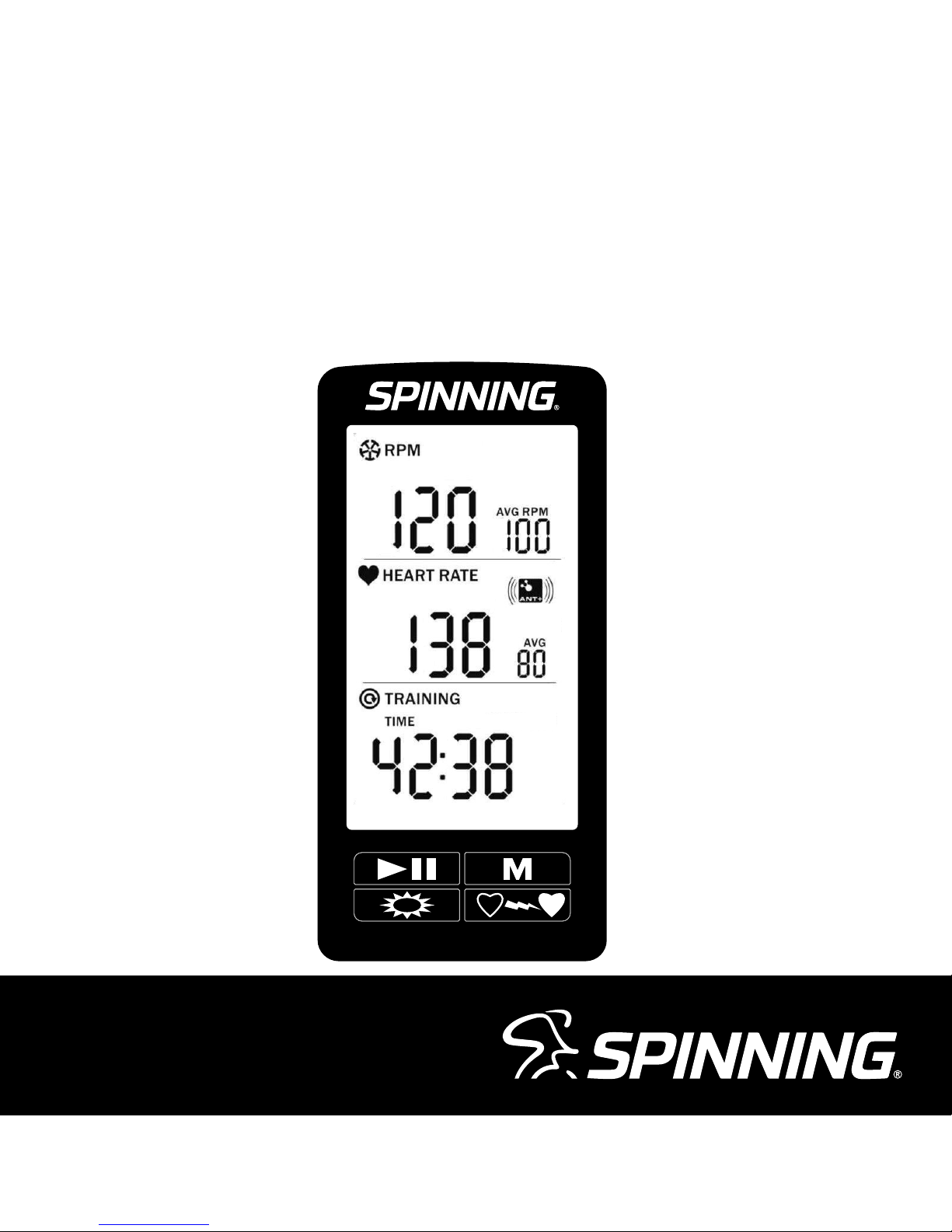
Thank you for purchasing the Spinning® Studio Computer. Heart rate
training is an essential aspect of the Spinning program, and this computer
will help you monitor your heart rate, cadence, time, distance and calories
burned on every ride. This owner’s manual will explain all of the key
features of this Computer, as well as take you through each step for
installing the Computer onto your Spinner® bike. Be sure to log on to
www.spinning.com for all the latest updates and information from Spinning.
Enjoy the ride!
SPINNING® STUDIO COMPUTER OWNER’S MANUAL
www.spinning.com 800.847.SPIN (7746)
5
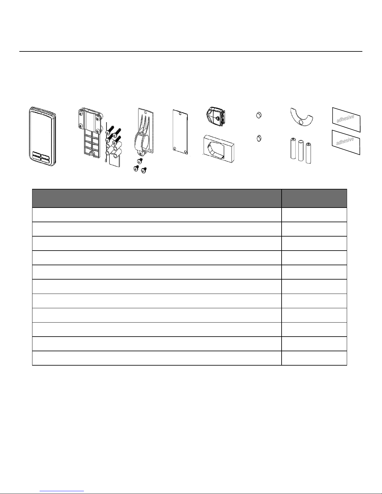
WHAT’S INSIDE
COMPONENT QUANTITY
1. Computer Console 1
2. Flat Mount Bracket with Four (4) Bolts and Spacers 1
3. Ring Mount Bracket with Three (3) Bolts 1
4. Rubber Gasket Inlay 1
5. Cadence Sensor 1
6. Cadence Sensor Foam Holder 1
7. 7A Magnet (Thick) 1
8. 7B Magnet (Thin) 1
9. Adhesive Magnet-Holding Shim 1
10. AAA Batteries for Computer Console 3
11. Double Stick Adhesive for Sensor Mounting 2
Tools Needed for Installation:
1. Phillips head screwdriver
2. 5mm hex key / Allen wrench (for removing the chain guard)
1. 2.
3. 4. 5.
6.
7. 9.
10.
11.
adhesive
adhesive
8.

©2015 Mad Dogg Athletics, Inc. All rights reserved. Spin®, Spinner®, Spinning®, Spin Fitness® and the Spinning logo ® are
registered trademarks that are owned by Mad Dogg Athletics, Inc.
ANT, ANT+ and the ANT+ logo are trademarks of Dynastream® Innovations Inc., a subsidiary of Garmin® Ltd.
6
COMPUTER FEATURES
Features:
• ANT+TM interoperable 2.4Ghz wireless technology
• Low power consumption for long battery life
• Code memory during battery displacement
• Large three line display; Cadence, Heart rate and Training data
• Bright LED backlight
• FCC ID: QSWASPDCS
• CE 1177 Certified
• ANT+ Certified
On-Screen Features:
• Cadence (measured in RPM) for current session
• Heart rate (measured in BPM) for current session
• Training data: Toggle the MODE button to see elapsed time,
equivalent distance traveled, and estimated calories burned
• Low battery indicator
General:
• ANT+ 2.4 GHz wireless radio to transmit data
• Batteries Required:
• Computer console uses 3 AAA batteries
• Cadence sensor uses 1 CR2032 lithium coin cell battery
• Life of batteries depends on usage
SPINNING® STUDIO COMPUTER OWNER’S MANUAL
www.spinning.com 800.847.SPIN (7746)
7
PAIRING WITH THE
CADENCE SENSOR
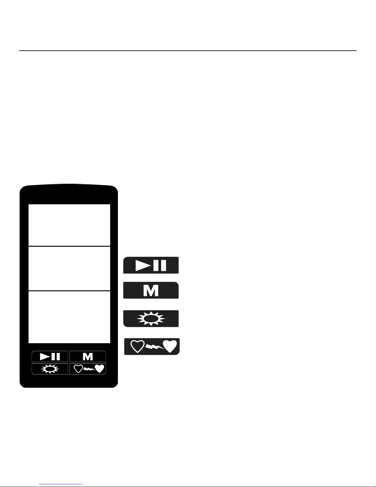
The Spinning® Studio Computer features a large, clear display that is
protected by a clear plastic sheet. The Computer also possesses a simple
four-button layout and was designed to pair with your heart rate transmitter
automatically.
Start/Pause/Resume
MODE Button
Backlight
Pair Heart Rate Transmitter
cadence
heart rate
time
distance
calories
©2016 Mad Dogg Athletics, Inc. All rights reserved. Spin®, Spinner®, Spinning®, Spin Fitness®, SPINPower® and
the Spinning logo ® are registered trademarks that are owned by Mad Dogg Athletics, Inc.
8
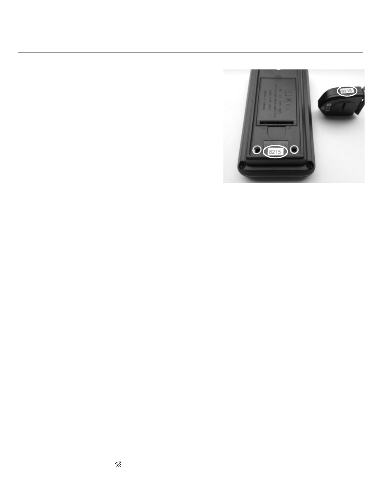
The console and cadence sensor will pair
right out of the box. Check the four-digit
code on the back of the console and
cadence sensor and ensure that they
match (Fig. 1). Once you confirm that they
match, just insert the three batteries into
the console and start your ride.
If the console does not immediately
pair with the cadence sensor,
please follow the instructions in the
“Advanced Settings” section on page
18. The “Advance Settings” section also
demonstrates how to adjust the backlight
time and distance settings.
F. 1
SPINNING® STUDIO COMPUTER OWNER’S MANUAL
www.spinning.com 800.847.SPIN (7746)
9
CADENCE SENSOR INSTALLATION
The Spinning® Studio Computer will track your cadence (measured in
RPM), time, distance and estimated calories burned. In order to track this
information, you must first attach the cadence sensor to the Spinner® bike.
We give you two options for mounting the sensor: inside the chain guard
or outside the chain guard. The components needed for the mounting
process will vary depending on your preferred method of installation and
your model of Spinner bike.
Mounting the Magnet:
NOTE: For the Spinner NXT Black Belt and Spinner Blade Belt, please use
the 7B (thinner) magnet. For all other Spinner bike models, please use the
7A (thicker) magnet.
1. Examine the inside of the right
crank arm and ensure that it
is clear of obstructions. Wipe
the inside of the crank arm to
remove any dust, grease and
grime.
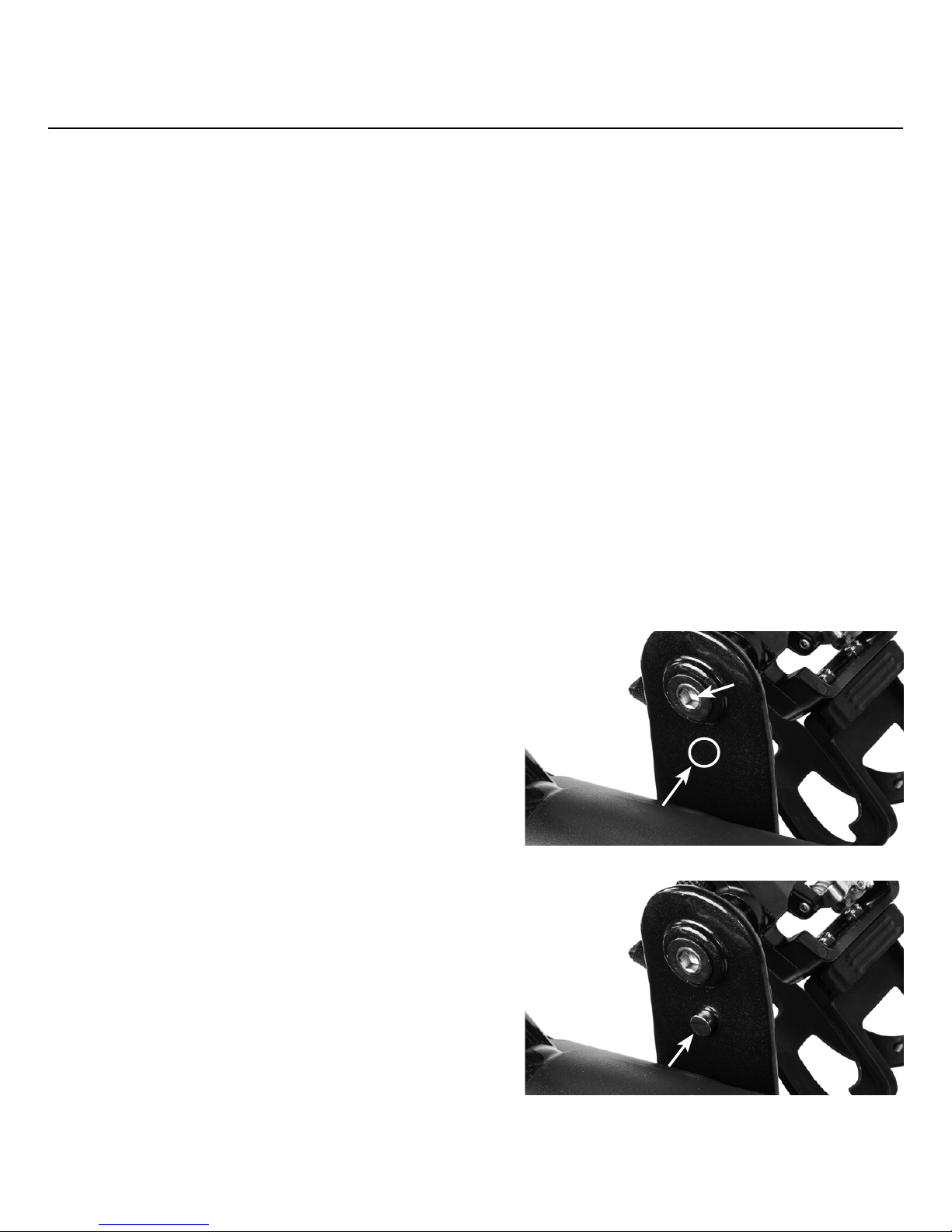
2. For all Spinner bikes built by
Precor®, place the magnet on
the inside the dedicated slot
near the pedal spindle (Fig 2
and 3). Slowly rotate the crank
arm to ensure that the magnet
does not collide with the chain
guard.
Fig. 2
pedal spindle
Fig. 3
magnet
magnet slot
 Loading...