

Page 1
Technical Product Documentation
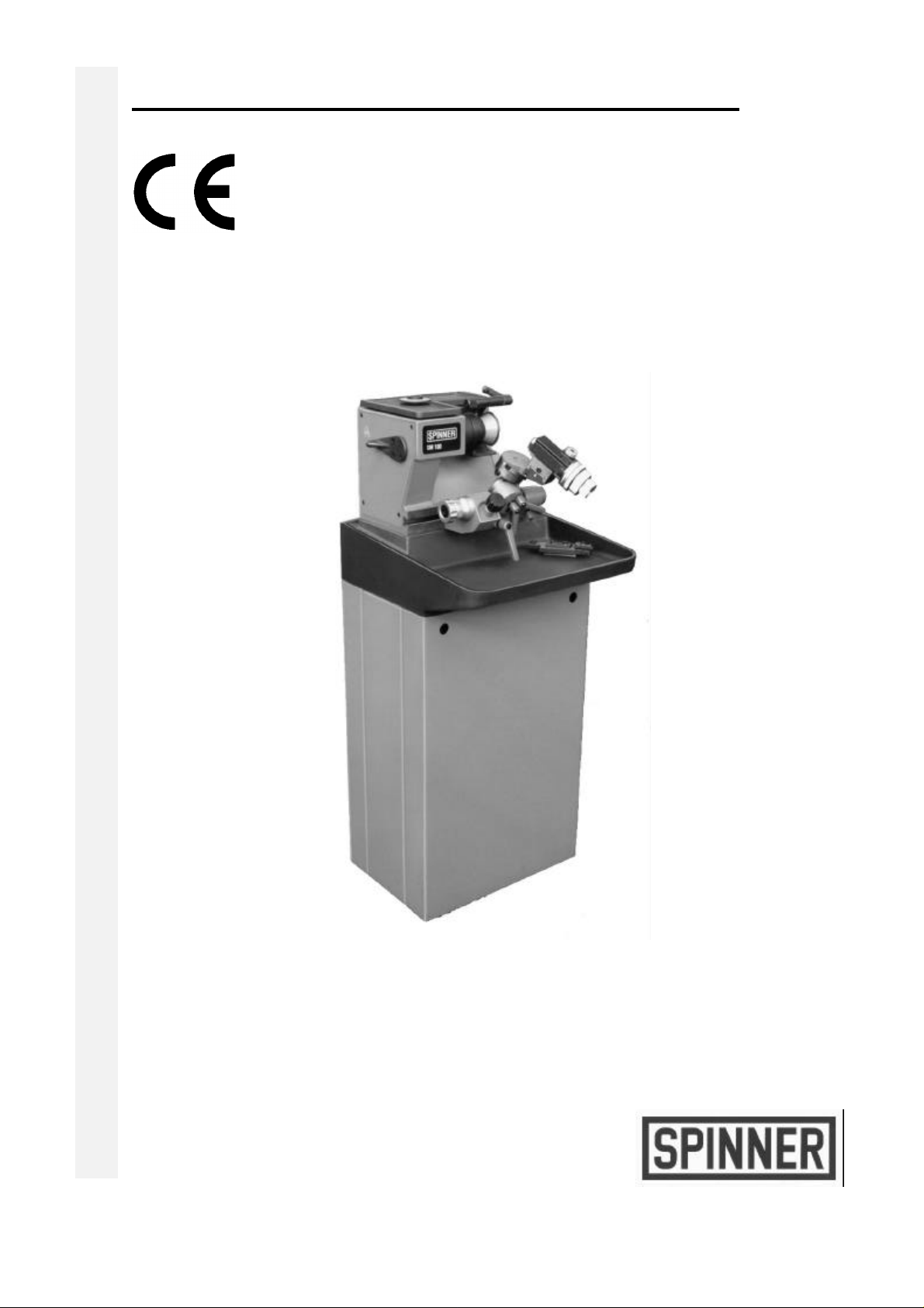
Tool grinder SM100
Serial number:
Version: SM-2-12/02
Valid until:
Article number: 61511
SPINNER WERKZEUGMASCHINENFABRIK GmbH
D-82054 Sauerlach, Rudolf-Diesel-Ring 24
Tel: +49 8104 / 803-0, Fax: +49 8104 / 803-19,
E-Mail: [email protected]; [email protected]
Page 2

Technical product documentation
Keep this Technical Product Documentation always
at the machine!
It must always be available!
SM-2-12/02
SPINNER Werkzeugmaschinenfabrik GmbH
2
Page 3

Technical product documentation
I. Table of contents
1 BASIC INFORMATION............................................................................................... 1-1
1.1 Basic information...................................................................................................................................1-2
2 BASIC SAFETY INFORMATION................................................................................ 2-1
2.1 Warnings and symbols...........................................................................................................................2-2
2.2 Appropriate use .....................................................................................................................................2-2
2.3 Application limits ..................................................................................................................................2-3
2.4 When the machine can be used..............................................................................................................2-3
2.5 Working safely – Organizational measures ...........................................................................................2-3
2.6 Personnel selection and qualifications...................................................................................................2-4
2.7 General hazards on the machine ............................................................................................................2-4
2.7.1 Mechanical hazards.........................................................................................................................2-4
2.8 Special types of hazards.........................................................................................................................2-4
2.8.1 Electrical .........................................................................................................................................2-4
2.8.2 Oil, grease and other chemical substances ......................................................................................2-5
2.9 Other hazards.........................................................................................................................................2-5
3 DESCRIPTION, TRANSPORTATION, INSTALLATION INSTRUCTIONS.................. 3-1
3.1 EC Declaration of conformity................................................................................................................3-2
3.2 Application............................................................................................................................................3-3
3.3 Technical data........................................................................................................................................3-3
3.3.1 Noise emission ................................................................................................................................3-3
3.4 Elements of delivery..............................................................................................................................3-4
3.4.1 Basic equipment..............................................................................................................................3-4
3.4.2 Special equipment...........................................................................................................................3-4
3.5 Transportation of the packed machine...................................................................................................3-5
3.6 Installation instruction...........................................................................................................................3-6
4 OPERATING ELEMENTS........................................................................................... 4-1
4.1 Clamping lever.......................................................................................................................................4-2
4.2 Operating elements................................................................................................................................4-2
4.3 Device to suck off the dust ....................................................................................................................4-3
5 ELECTRICAL CONNECTION..................................................................................... 5-1
5.1 Electrical connection .............................................................................................................................5-2
6 MAINTENANCE INSTRUCTION................................................................................. 6-1
6.1 Maintenance instruction.........................................................................................................................6-2
7 QUICK CHANGE UNIT FOR GRINDING WHEEL...................................................... 7-1
7.1 Quick change unit for grinding wheel....................................................................................................7-2
8 ASSEMBLY OF THE GRINDING WHEEL FLANGE .................................................. 8-1
8.1 Assembly of the grinding wheel flange..................................................................................................8-2
8.2 Assembly fittings...................................................................................................................................8-2
8.3 Assembly...............................................................................................................................................8-2
8.4 Grinding wheels.....................................................................................................................................8-3
9 DRESSING THE GRINDING WHEEL......................................................................... 9-1
9.1 Operating elements................................................................................................................................9-2
9.2 Handling................................................................................................................................................9-2
10 UNIVERSAL SWIVEL HOLDER............................................................................. 10-1
10.1 Universal swivel holder.....................................................................................................................10-2
11 DIVIDING APPARATUS ......................................................................................... 11-1
11.1 Dividing apparatus.............................................................................................................................11-2
SM-2-12/02
SPINNER Werkzeugmaschinenfabrik GmbH
3
Page 4

Technical product documentation
12 CLAMPING PLATE FOR SQUARE TOOLS........................................................... 12-1
12.1 Clamping plate for square tools.........................................................................................................12-2
13 GRINDING THE RADIUS ....................................................................................... 13-1
13.1 Grinding the radius............................................................................................................................13-2
14 GRINDING THE CUTTER....................................................................................... 14-1
14.1 Grinding the cutter.............................................................................................................................14-2
15 COOLANT UNIT..................................................................................................... 15-1
15.1 Coolant unit .......................................................................................................................................15-2
15.1.1 Recommended coolant................................................................................................................15-3
16 ACCESSORIES...................................................................................................... 16-1
16.1 Accessories........................................................................................................................................16-2
16.2 Other accessories (if not delivered with the machine).......................................................................16-3
17 CIRCUIT DIAGRAM................................................................................................ 17-1
17.1 Circuit diagram..................................................................................................................................17-2
18 MICROSCOPE ....................................................................................................... 18-1
18.1 Mikroskope........................................................................................................................................18-2
18.1.1 Axial adjustment of the microscope............................................................................................18-2
18.1.2 Radial adjustment of the microscope...........................................................................................18-3
SM-2-12/02
SPINNER Werkzeugmaschinenfabrik GmbH
4
Page 5

Technical product documentation
II. Index
A
Accessories ....................................................................................................................................................................3-4; 16-3
Adjusting the clearance angle ................................................................................................................................................10-5
Adjustment scale....................................................................................................................................................................10-4
Appropriate use........................................................................................................................................................................2-2
C
Centering bracket...................................................................................................................................................................13-2
Circuit diagram......................................................................................................................................................................17-2
Clamping plate for square tools .............................................................................................................................................12-2
Connection of the coolant pump..............................................................................................................................................5-3
Contacting aid........................................................................................................................................................................13-2
Coolant unit ...........................................................................................................................................................................15-2
Cross table .............................................................................................................................................................................10-3
Cutter grinding.......................................................................................................................................................................14-2
D
Dividing apparatus.................................................................................................................................................................11-2
Dressing the grinding wheel ....................................................................................................................................................9-2
E
Electrical connection................................................................................................................................................................5-2
G
Grinding the cutter.................................................................................................................................................................14-2
Grinding the radius ................................................................................................................................................................13-2
Grinding wheel flange (assembly)............................................................................................................................................8-2
Grinding wheels.......................................................................................................................................................................8-3
M
Main connection ......................................................................................................................................................................5-2
Maintenance instructions.........................................................................................................................................................6-2
O
Operating elements ..................................................................................................................................................................4-2
Q
Quick change unit....................................................................................................................................................................7-2
R
Radius grinding......................................................................................................................................................................13-2
U
Universal swivel holder .........................................................................................................................................................10-2
W
Warnings and symbols.............................................................................................................................................................2-2
SM-2-12/02
SPINNER Werkzeugmaschinenfabrik GmbH
5
Page 6

Technical product documentation
III. List of figures
Figure 3-1: Transportation of the grinding machine.............................................................................................3-5
Figure 3-2: Installation instruction........................................................................................................................3-6
Figure 4-1: Operating elements ............................................................................................................................4-2
Figure 4-2: Device to suck off the dust.................................................................................................................4-4
Figure 5-1: Main connection.................................................................................................................................5-2
Figure 5-2: Sockets...............................................................................................................................................5-2
Figure 5-3: Coolant pump.....................................................................................................................................5-3
Figure 6-1: Maintenance instructions for the grinding spindle .............................................................................6-2
Figure 6-2: Lubricating the swivel holder.............................................................................................................6-2
Figure 6-3: Lubricating the dividing apparatus.....................................................................................................6-3
Figure 7-1: Quick change unit - lever “closed“.....................................................................................................7-2
Figure 7-2: Quick change unit - lever “open“.......................................................................................................7-2
Figure 7-3: Quick change unit - changing the grinding wheel..............................................................................7-3
Figure 8-1: Assembly fittings................................................................................................................................8-2
Figure 8-2: Assembly............................................................................................................................................8-3
Figure 8-3: Grinding wheels.................................................................................................................................8-3
Figure 9-1: Operating elements ............................................................................................................................9-2
Figure 9-2: Handling.............................................................................................................................................9-3
Figure 10-1: Clamping lever and adjusting elements..........................................................................................10-2
Figure 10-2: Cross table......................................................................................................................................10-2
Figure 10-3: Cross table......................................................................................................................................10-3
Figure 10-4: Fine adjustment..............................................................................................................................10-3
Figure 10-5: Swivel movement...........................................................................................................................10-4
Figure 10-6: Adjustment scale............................................................................................................................10-4
Figure 10-7: Handling.........................................................................................................................................10-5
Figure 10-8: Adjusting the clearance angle ........................................................................................................10-5
Figure 11-1: Dividing apparatus.........................................................................................................................11-2
Figure 11-2: Shifting the dividing apparatus ......................................................................................................11-2
Figure 11-3: Adjusting the dividing scale...........................................................................................................11-3
Figure 11-4: Handling.........................................................................................................................................11-3
Figure 11-5: Indexing.........................................................................................................................................11-4
Figure 11-6: Grinding.........................................................................................................................................11-4
Figure 12-1: Clamping plate...............................................................................................................................12-2
Figure 12-2: Clamping bracket of the camping plate..........................................................................................12-2
Figure 12-3: Stopper...........................................................................................................................................12-3
Figure 13-1: Centering bracket...........................................................................................................................13-2
Figure 13-2: Contacting the tool.........................................................................................................................13-2
Figure 13-3: Contacting the tool.........................................................................................................................13-3
Figure 13-4: Adjusting the radius.......................................................................................................................13-3
Figure 13-5: Adjusting the radius.......................................................................................................................13-4
Figure 13-6: Adjusting the clearance angle ........................................................................................................13-5
Figure 13-7: Turning angle.................................................................................................................................13-5
Figure 13-8: Grinding the radius.........................................................................................................................13-6
Figure 13-9: Grinding the radius.........................................................................................................................13-6
Figure 13-10: Grinding the radius.......................................................................................................................13-7
Figure 13-11: Grinding the radius.......................................................................................................................13-7
Figure 14-1: Halving the cutter...........................................................................................................................14-2
Figure 14-2: Halving the cutter...........................................................................................................................14-2
Figure 14-3: Grinding the cutter.........................................................................................................................14-3
Figure 14-4: Setting the turning angle ................................................................................................................14-3
Figure 14-5: Adjusting the turning angle............................................................................................................14-4
Figure 14-6: Setting the clearance angle.............................................................................................................14-4
Figure 14-7: Grinding the cutter.........................................................................................................................14-5
Figure 14-8: Grinding the cutter.........................................................................................................................14-5
Figure 14-9: Handling.........................................................................................................................................14-6
Figure 14-10: Grinding the cutter relief..............................................................................................................14-6
Figure 14-11: Grinding the cutter relief..............................................................................................................14-7
Figure 14-12: Milling cutter ...............................................................................................................................14-7
Figure 15-1: Coolant unit....................................................................................................................................15-2
Figure 15-2: Coolant hose ..................................................................................................................................15-3
SM-2-12/02
SPINNER Werkzeugmaschinenfabrik GmbH
6
Page 7

Technical product documentation
Figure 18-1: Microscope ....................................................................................................................................18-2
Figure 18-2: Axial adjustment of the microscope...............................................................................................18-2
Figure 18-3: Radial adjustment of the microscope .............................................................................................18-3
SM-2-12/02
SPINNER Werkzeugmaschinenfabrik GmbH
7
Page 8

Basic information
Technical Product Documentation
Machine type: Tool grinder SM100
Serial number:
Version: SM-1-03/02
Valid until:
Article number: 61511E
1 Basic information
SM-1-03/02
SPINNER Werkzeugmaschinenfabrik GmbH
1-1
Page 9

Basic information
1.1 Basic information
This technical product documentation should make it easier for you to familiarize yourself
with the machine and use the machine in accordance with its intended areas of
application.
The document contains important information on how to safely, correctly and
economically use the machine. Paying close attention will help you to avoid hazardous
situations, reduce repair costs and down-times and increase the reliability and life span of
the machine.
The technical product documentation includes instructions on how to prevent accidents
and help protect the environment in accordance with the existing national laws relating to
these subjects. The documentation must always be available at the location where the
machine is used.
The documentation is to be read and used by everyone who works on the machine, for
example, persons who are assigned to carry out the following tasks:
− Operation, including setup, correcting errors in the work procedure, care and disposal of
operational and additional materials
− Maintenance (maintenance, inspection, repair) and/or
− Transportation
The recognized technical regulations relating to the safe operation and appropriate usage
of the machine are to be observed in addition to the technical product documentation and
the applicable regulations relating to accident prevention in the country where the
machine is used.
The personnel assigned to carry out tasks on the machine must have read and
understood the technical product documentation, especially the chapter "Basic safety
instructions", before he or she begins working on the machine. It is too late to start
reading this material once you have started working. The basic safety instructions must
be observed.
The technical product documentation was created in accordance with the following
guidelines and norms:
− Machine guideline 89/392/EC of the commission dated June 14, 1989 to
standardize the legal guidelines of the member states for machines in draft
93/68/EC
− VDI 4500 Sheet 1: Technical documentation – Information for user (1995)
− DIN V 8418: User's information – References for the presentation (1988)
− DIN EN 292 Part 1 and 2: Safety of machinery – Basic terminology, methodology
(1991)
The Spinner company reserves the right to make changes at any time to the product
without prior notification. In addition, the information contained in this technical product
documentation can be changed without prior notification.
The SPINNER company assumes no responsibility for faults and consequential damage
which arises due to the use or misinterpretation of the information in this documentation.
SM-1-03/02
SPINNER Werkzeugmaschinenfabrik GmbH
1-2
Page 10

Basic information
This technical product documentation contains copyright information protected by
copyrights. All rights reserved. It is not permitted to reprint, photocopy or store this
technical product documentation or any excerpt on an electronic storage medium without
the expressed consent of the Spinner company.
Spinner Werkzeugmaschinenfabrik GmbH
SM-1-03/02
SPINNER Werkzeugmaschinenfabrik GmbH
1-3
Page 11

Basic safety information
Technical Product Documentation
Machine type: Tool grinder SM100
Serial number:
Version: SM-2-12/02
Valid until:
Article number: 61511E
2 Basic safety information
SM-2-12/02
SPINNER Werkzeugmaschinenfabrik GmbH
2-1
Page 12

Basic safety information
2.1 Warnings and symbols
Special statements/information regarding the (economic) use of
The following designations and symbols are used for especially important information in
this technical product documentation:
DANGER
Information, regulations and prohibitions to prevent bodily harm
CAUTION
Special information, regulations and prohibitions to prevent
damage to equipment and materials
NOTE
F
the machine
2.2 Appropriate use
The machine is built in accordance with the current state of the technology and
recognized safety regulations. However, the machine can be a source of danger when it
is not used by trained, or at least instructed, personnel, or when it is used incorrectly or
for something for which it is not intended. The following can occur in these cases:
• Danger of bodily injury or death of the user or others
• Damage to the machine and other material goods belonging to the user
• Inefficient operation of the machine
Only use the machine when it is in technically perfect condition and for its intended
purpose, and be aware of the hazards and safety instructions stated in this technical
product documentation! In particular, correct (or have someone correct) any malfunctions
that affect the safety of the machine immediately!
The machine is only to be used for tool grinding that means to manufacture and sharp
small cutting tools using the tools intended for this purpose. Both the use of this machine
for any other use and the overloading of the machine are considered inappropriate usage.
The manufacturer is not liable for any damage resulting from inappropriate use. The user
alone carries the responsibility in this case.
Appropriate use also includes the observance of the operation, maintenance and repair
guidelines as well as of the information in the technical product documentation.
You may not make any changes or structural modifications to the machine or add
equipment that may affect the safety of the machine without authorization from the
supplier. This also applies to the installation and setup of safety equipment.
SM-2-12/02
SPINNER Werkzeugmaschinenfabrik GmbH
2-2
Page 13

Basic safety information
2.3 Application limits
The application limits are determined by the maximum values of the machine, especially
those for:
• Largest radius that can be ground
• Largest adjustment of the swivel holder parallel to the grinding spindle
• Largest adjustment at the side over the cross slide
• Length of the clamping collet
These values are listed in the technical data. Familiarize yourself with this data before
using the machine to avoid severely damaging the machine.
2.4 When the machine can be used
• You are only to operate the machine when all safety equipment and safetyrelated equipment, e.g. removable safety equipment or exhaust equipment, are
available and function properly!
2.5 Working safely – Organizational measures
• Do not carry out any work steps that negatively affect the safety of the machine!
• All information on hazards on the machine are to be observed!
• All safety information and information on hazards on the machine are to be
maintained in a readable format together with all related documentation!
• The personnel should not have long exposed hair or wear loose clothing or
jewelry (including rings), otherwise there is a danger of bodily harm (e.g. when
clothing gets caught or the operator is pulled into the machine)! The operator
must conform to the personal safety measures in the national regulations related
to accident prevention (hair net, protective goggles, gloves, ear plugs or related
gear, protective steel-tipped shoes, etc.)!
• Check at regular intervals to ensure that the personnel are aware of the safety
measures and dangers in accordance with the technical product documentation!
• The responsibilities for the various tasks to be carried out in conjunction with the
operation of the machine must be clearly defined and maintained so that there
are no undefined areas of responsibility when it comes to safety! When making
changes to the machine that affect its safety or changing the way you operate
the machine, switch off the machine immediately and inform the office/person
responsible!
• Original parts and accessories are specially designed for this machine. We would
especially like to call your attention to the fact that original parts and accessories
not supplied by us have also not been tested and released by us! The installation
and/or the use of such products can therefore negatively affect the structural
properties of the machine! The manufacturer is not liable for any damage that
results from the use of parts and accessories that are not original parts and
accessories!
• Observe the fire prevention regulations when handling flammable materials!
• Switch off the machine immediately and lock it when a malfunction occurs! Have
the malfunction corrected as soon as possible!
• Before switching on or engaging the machine, make sure that no one will be
placed in a hazardous situation as a result of the machine startup!
• Observe and maintain the prescribed setup, maintenance, and inspection tasks
and schedules, including those specifications regarding the exchanging of
parts/components, in the technical product documentation! These tasks may only
be carried out by trained personnel!
SM-2-12/02
SPINNER Werkzeugmaschinenfabrik GmbH
2-3
Page 14

Basic safety information
• If the machine is switched off completely for maintenance and repair work, then it
must be protected against an unexpected startup!
• Ensure that the operational and auxiliary materials, as well as old, exchanged
parts, are disposed of in a safe and environmentally sound manner!
• The operator must also make sure that no unauthorized persons work on the
machine!
• The operator is required to inspect the machine at least once per shift for
external damage and defects, and to inform the appropriate persons when a
change is discovered that affects the safety (and operation) of the machine!
• If the safety equipment needs to be removed when adding new equipment to the
machine or when carrying out maintenance or repair work, then the safety
equipment must be remounted and inspected immediately after the maintenance
and repair work is completed!
2.6 Personnel selection and qualifications
• Allow only trained or instructed personnel to work on the machine! Clearly define
which persons are responsible for the operation, equipping, maintenance and
repair of the machine!
• Make sure that the only persons that work on the machine are those assigned to
work on the machine!
• Personnel in training, receiving instructions or who are still in a general training
program are only to be allowed on the machine when under constant supervision
by experienced personnel!
• Work done on the electrical equipment of the machine may only be carried out
by an electrician or by trained personnel under the guidance and supervision of
an electrician in accordance with the regulations relating to electrical systems!
Work done on the hydraulic equipment of the machine may only be carried out
by personnel with special knowledge and experience in hydraulics! The
appropriate tools and equipment must be available!
2.7 General hazards on the machine
2.7.1 Mechanical hazards
• Danger of bodily injury in the form of bruises, cuts, bumps, stab wounds,
abrasions or any other injuries resulting from getting pulled into the machine,
etc.! These dangers are presented mainly by the moving machine parts, sharpedged workpieces/ sharp chips and filings, sharp tools, etc.! Do not reach into
moving machine parts!
2.8 Special types of hazards
2.8.1 Electrical
• Use only original circuit breakers with the prescribed current and voltage ratings.
Switch off the machine immediately when a malfunction in the electrical supply of
the machine is discovered!
• Work done on the electrical equipment or operating materials of the machine
may only be carried out by an electrician or by trained personnel under the
guidance and supervision of an electrician in accordance with the regulations
relating to electrical systems.
• Machine and equipment parts on which inspection, maintenance and repair work
must be done may not carry current or be under voltage when conducting such
work! Switch off the corresponding equipment!
SM-2-12/02
SPINNER Werkzeugmaschinenfabrik GmbH
2-4
Page 15

Basic safety information
• The electrical equipment of a machine is to be inspected regularly. Defects such
as loose connections must be repaired immediately!
2.8.2 Oil, grease and other chemical substances
• You must observe the applicable safety regulations for the product when
handling oil, grease and other chemical substances!
2.9 Other hazards
There is still a small potential for danger that cannot be eliminated even if you have taken
all safety precautions. These dangers may only arise under certain circumstances or
cannot be recognised as hazardous. We would especially like to point out that you should
pay attention every time you use the machine. Inattention can lead to bodily injury and
damaged equipment.
SM-2-12/02
SPINNER Werkzeugmaschinenfabrik GmbH
2-5
Page 16

Description, Transportation, Installation instructions
Technical Product Documentation
Machine type: Tool grinder SM100
Serial number:
Version: SM-2-12/02
Valid until:
Article number: 61511E
3 Description, Transportation, Installation
instructions
SM-2-12/02
SPINNER Werkzeugmaschinenfabrik GmbH
3-1
Page 17
Description, Transportation, Installation instructions
3.1 EC Declaration of conformity
EC Declaration of conformity
as defined by the EC machine direction 98/37/EC
EC direction Electromagnetic compatibility 89/336/EEC
EC direction Low voltage 73/23/EEC
The machine
Description
Type
Serial number
has been developed, designed and built according to the above mentioned EC directions in the own
risk of:
Company
If the machine has been modified or changed by the enduser, this certificate is not valid any more.
The following harmonised standards have been used:
EN 294 EN 13218
EN 292 T1 EN 61000-6-2
EN 563 EN 61000-6-4
EN 954-1 EN 60204 T1
Tool grinder
SM100
SPINNER Werkzeugmaschinenfabrik GmbH
Rudolf-Diesel-Ring 24
D-82054 Sauerlach (bei München)
Tel.: +49 8104/803-0; Fax: +49 8104/803-19
E-Mail: [email protected]; [email protected]
Sauerlach, December 2002 .......................................................................
SM-2-12/02
SPINNER Werkzeugmaschinenfabrik GmbH
Nicolaus Spinner, Dipl. Ing (FH)
(Authorized signatory)
3-2
Page 18

Description, Transportation, Installation instructions
3.2 Application
The series SM100 is a small and compact grinding machine which can be used in a large
number of applications in workshops. The machine serves only to produce and grind
small cutting tools. The machine can be delivered as table machine or as machine with
coolant tank and base.
You can use grinding wheels with an outer diameter up to 100mm and a drilling of 25mm.
The max. height of the wheel is 50mm.
The machine can be equipped from a simple hand support on up to a comfortable dividing
apparatus. The grinding wheels can be changed in a matter of seconds by means of a
quick change unit which is patented.
3.3 Technical data
Electrical connection 230V AC, 50/60Hz
Power of the drive motor 250 watt
Revolutions per minute of the drive motor 2800 rpm
Revolutions per minute of the grinding spindle 4500 rpm
Largest radius that can be ground
- with swivel holder ca. 20
- with dividing apparatus ca. 10
Largest adjustment of the swivel holder parallel to the
grinding spindle
- Coarse adjustment by hand ca. 120
- Fine adjustment by micrometer ca. 15
Largest adjustment to the side over the cross slide ca. +/-10mm
Largest longitudinal adjustment
- of the tool holder plate ca. 30mm
- of the dividing apparatus ca. 50mm
Dividing apparatus
- Scale 360 degrees
- Engaging disk 12 fold
- Clamping collet 355 E up to 17.5mm,
alternatively W25 up to
25mm or with reduction
sleeve collets W20 up to
20mm
3.3.1 Noise emission
Determined sound pressure level according to the engineering method in an essential
free field over a reflecting plane DIN EN ISO 3744
Emission sound pressure level at a work station according to DIN EN ISO 11204
Condition of work: Sharpening a cutting tool = 74 dB(A)
SM-2-12/02
SPINNER Werkzeugmaschinenfabrik GmbH
3-3
Page 19

Description, Transportation, Installation instructions
3.4 Elements of delivery
ACCESSORIES FROM SPINNER!
3.4.1 Basic equipment
Table machine with base plate (basic machine SM100)
1 Technical manual
1 Socket screw wrench, 5mm, 6edges
1 Grease gun, 1 cable
1 socket wrench/box spanner for grinding wheel flange
Basic body with motor and complete electrical equipment 230V, 50/60 Hz
Quick change device for grinding wheel
Grinding wheel cover with wheel dresser without diamond
T-groove ledge to fix accessories
3.4.2 Special equipment
1) Grinding wheel flange
2) Grinding wheels in form T/I/II/III
3) Dressing diamond
4) Support for the hands (all-round adjustable)
5) Swivel holder with cross slide
6) Support for square tools with clamp
7) Dividing apparatus for collets 355E up to 17,5mm
8) Dividing apparatus for collets W25 up to 25mm or with reducing for collets
W20 up to 20mm
9) Single collets or sets
10) Collets with special design
11) Inserts W25 with MK1/2/3
12) Special clamping device
The table machine can be extended with:
1) Base SM100
2) Tank with coolant supply
ONLY USE ORIGINAL REPLACEMENT PARTS AND
SM-2-12/02
SPINNER Werkzeugmaschinenfabrik GmbH
3-4
Page 20
Description, Transportation, Installation instructions
3.5 Transportation of the packed machine
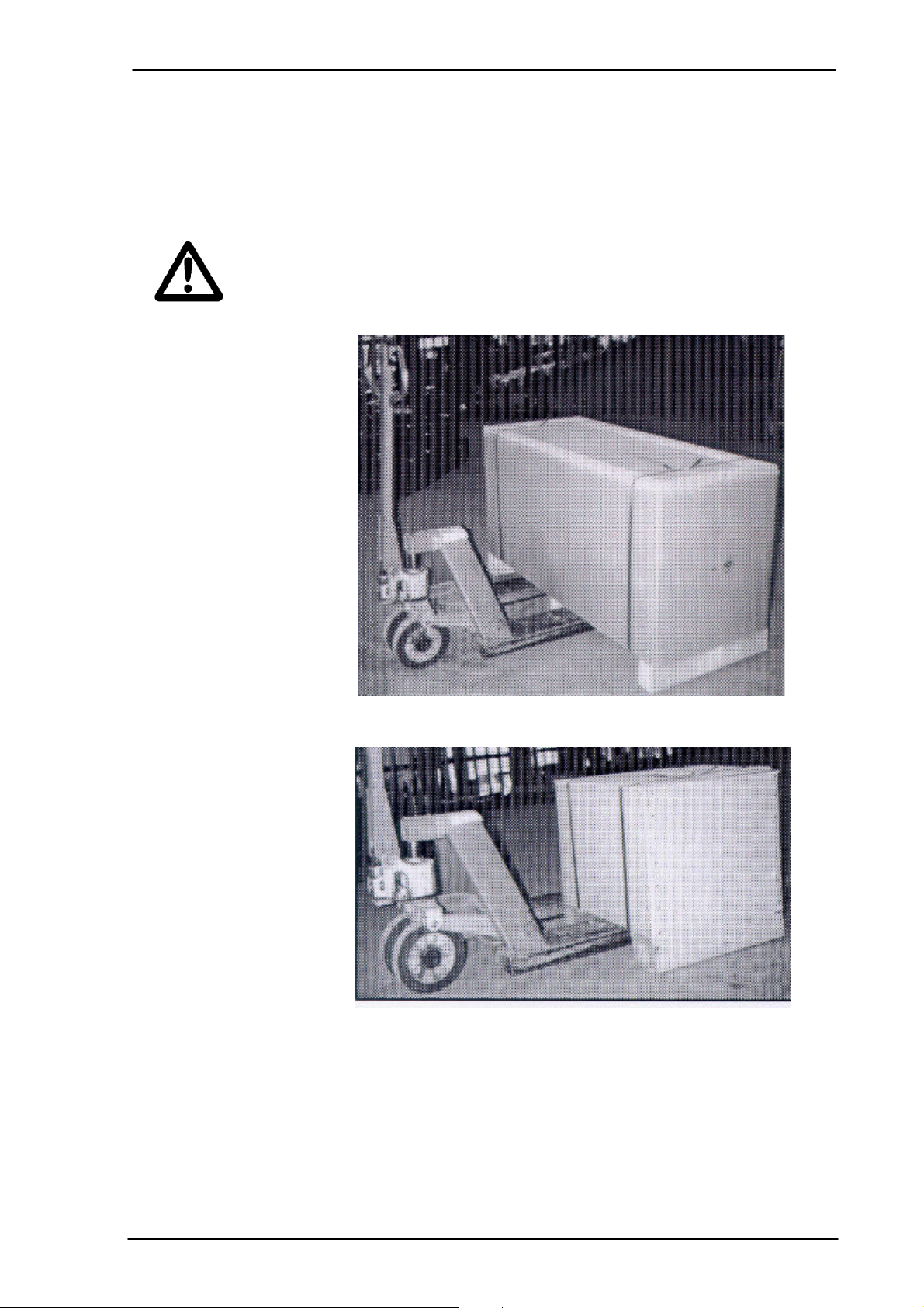
The machines are delivered as shown in the figures below. Only transport the good with a
lift truck of appropriate length! We recommend to unpack and install the machine only on
the installation site. Lift the machine carefully from the pallet.
THE MACHINE SHOULD SET DOWN WITH EXTREME CARE!
MAKE SURE THAT THE TRANSPORTATION GOOD DOES NOT
FALL!
Weight: about 150kg
Weight: about 50kg
Figure 3-1: Transportation of the grinding machine
SM-2-12/02
SPINNER Werkzeugmaschinenfabrik GmbH
3-5
Page 21
Description, Transportation, Installation instructions
3.6 Installation instruction
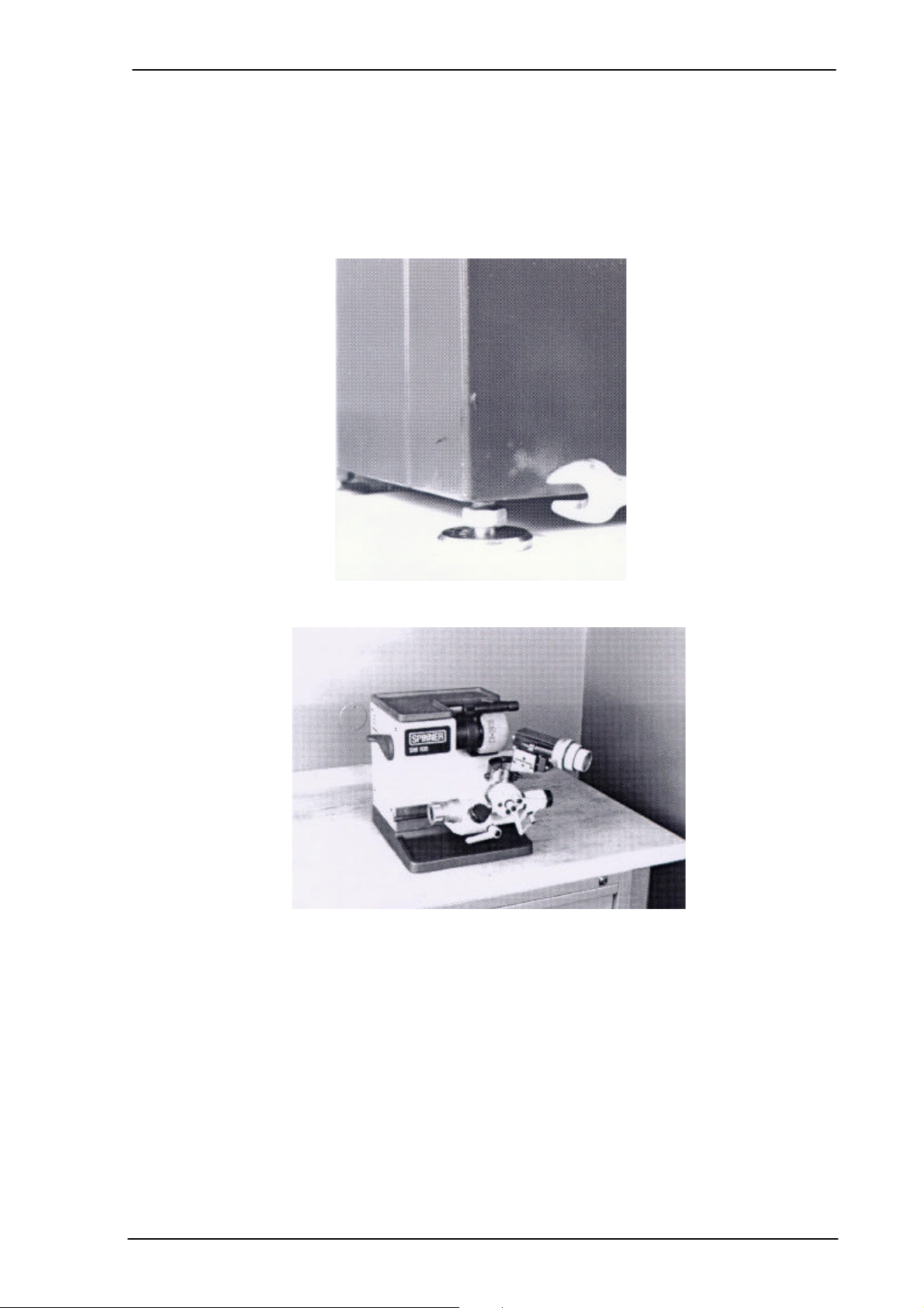
Align the machine with the assistance of the adjustable base legs integrated into the
base. These can be moved with the assistance of an SW 24 spanner. Four support liners
are already included in the machine delivery.
The alignment of the table machine is not necessary. It is advisable to install the machine
onto a workbench.
Figure 3-2: Installation instruction
SM-2-12/02
SPINNER Werkzeugmaschinenfabrik GmbH
3-6
Page 22

Operating elements
Technical Product Documentation
Machine type: Tool grinder SM100
Serial number:
Version: SM-2-12/02
Valid until:
Article number: 61511E
4 Operating elements
SM-2-12/02
SPINNER Werkzeugmaschinenfabrik GmbH
4-1
Page 23
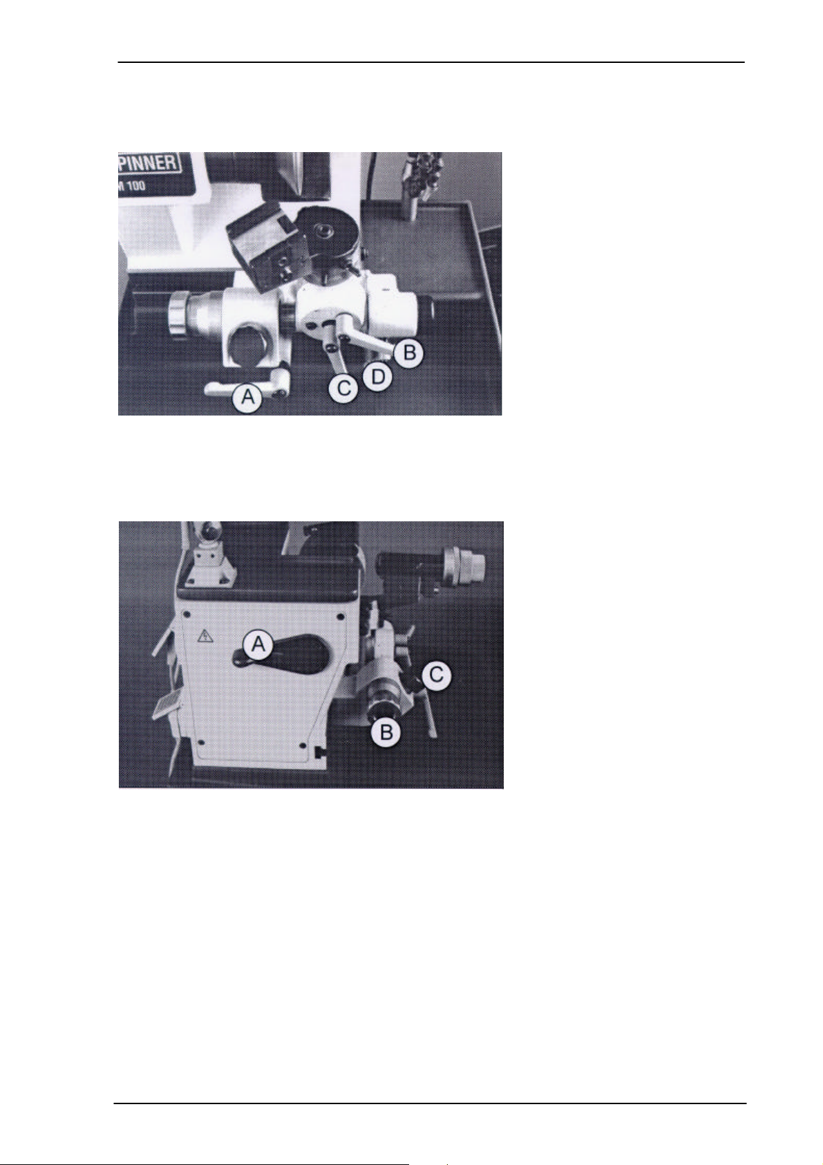
Operating elements
4.1 Clamping lever
A)
A)
Adjusting screw for the infeed of
4.2 Operating elements
Central clamp for complete
swivel holder
B) Clamp for swivel movement
C) Clamp for rotary movement
D) Clamp for tilting movement
Figure 4-1: Operating elements
Lever for changing the grinding
wheel
B)
the tool to the grinding wheel
C) Stopper for tilting movement
SM-2-12/02
SPINNER Werkzeugmaschinenfabrik GmbH
4-2
Page 24

Operating elements
4.3 Device to suck off the dust
When grinding cutting metal tools it is absolutely necessary to intsall a device to suck off
the dust.
The capacity of the suck off device must match with the quantity of dust which comes up.
Only use appropriate suck off devices.
An appropriate device to suck off the dusk with the corresponding suck off pipe can be
ordered at:
LUTZ Absaug-Technik GmbH
Schleifweg 7
D-74257 Untereisesheim
Tel. 07132/6966; Fax 07132/6688
by means of the following technical data:
BoTech Iindustrial suction system for continuous operation Type 140S - CE, Article 10401
Crude gas passage: 240 m³/h
Subpressure: 1.500 mm WS (15.000Pa)
Number of cartridges: 2x Ø200 mm
Total filter surface: 0.8 m²
Material: High-performance-Polyester
Fibre fleece
Degree of deposit in case of particles of
3,2 µm = >99,9%
Filter category: BIA „C“ (suitable for noxious dust)
Passage in %: smaller than 0,1%
Dust collector: in dust collector mounted underneath,
removable
Capacity about 15 litres
With:
1 phase motor 1,1 kW, 230 V, 50 Hz
Spiral suction pipe PVC, DN 50 mm - 2 m
Pipe socket to be screw on, DN 50mm
Magnet rack with pipe nozzle, DN 50 mm
SM-2-12/02
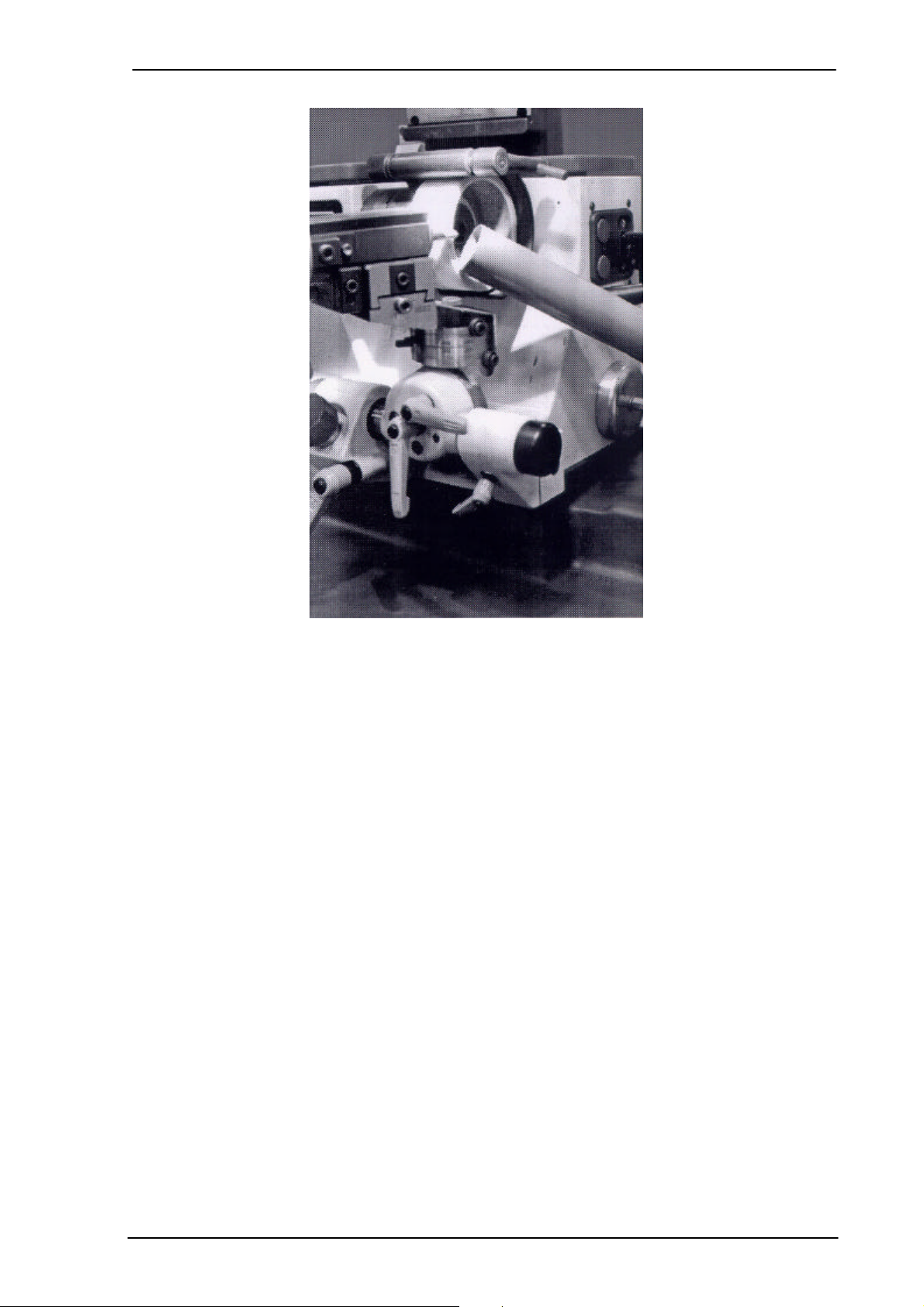
The installation of the suck off pipe can be as shown in the figure below.
You can also use industrial suction systems from other manufacturers which must meet
the above mentioned conditions.
Check regularly the function and dirt of the filters and rallying container of the suck off
device. Check also if there are leaks.
Clean and check the filters regularly according to the information of the manufacturer.
SPINNER Werkzeugmaschinenfabrik GmbH
4-3
Page 25
Operating elements
Figure 4-2: Device to suck off the dust
SM-2-12/02
SPINNER Werkzeugmaschinenfabrik GmbH
4-4
Page 26

Electrical connection
Technical Product Documentation
Machine type: Tool grinder SM100
Serial number:
Version: SM-1-03/02
Valid until:
Article number: 61511E
5 Electrical connection
SM-1-03/02
SPINNER Werkzeugmaschinenfabrik GmbH
5-1
Page 27
Electrical connection
5.1 Electrical connection
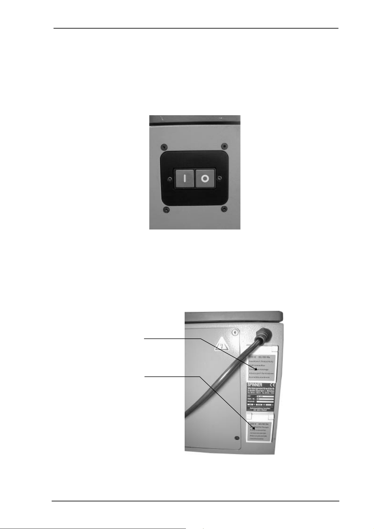
Main connection:
230V, 50/60Hz is required as the supply voltage. The central connection is carried out by
means of the provided cable.
Push buttons:
Red O: Grinding spindle stop
Green I: Grinding spindle start
Figure 5-1: Main connection
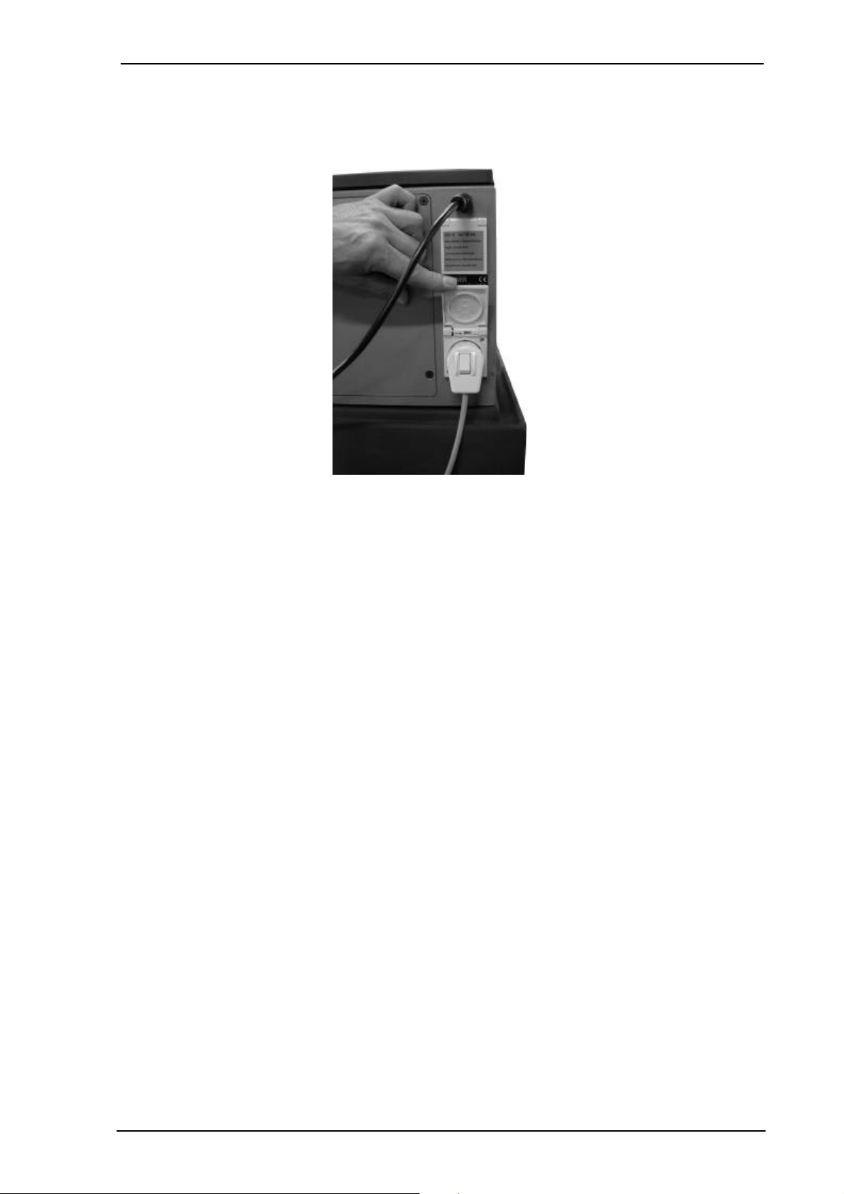
Sockets:
Two sockets are mounted on the rear side of the machine. The machine lamp can be
plugged into the upper socket. The coolant pump can be plugged into the lower socket.
Overload circuit breaker:
An overload circuit breaker for the spindle motor is located beneath the sockets.
Machine lamp
Coolant pump
SM-1-03/02
Figure 5-2: Sockets
SPINNER Werkzeugmaschinenfabrik GmbH
5-2
Page 28
Electrical connection
Coolant pump:
The plug of the coolant pump has an integrated switch. When the coolant pomp is
switched on it will only start when the grinding wheel starts. If the grinding wheel is
switched off, the coolant pomp is also stopped.
Figure 5-3: Coolant pump
SM-1-03/02
SPINNER Werkzeugmaschinenfabrik GmbH
5-3
Page 29

Maintenance instruction
Technical Product Documentation
Machine type: Tool grinder SM100
Serial number:
Version: SM-2-12/02
Valid until:
Article number: 615011E
6 Maintenance instruction
SM-2-12/02
SPINNER Werkzeugmaschinenfabrik GmbH
6-1
Page 30
Maintenance instruction
6.1 Maintenance instruction
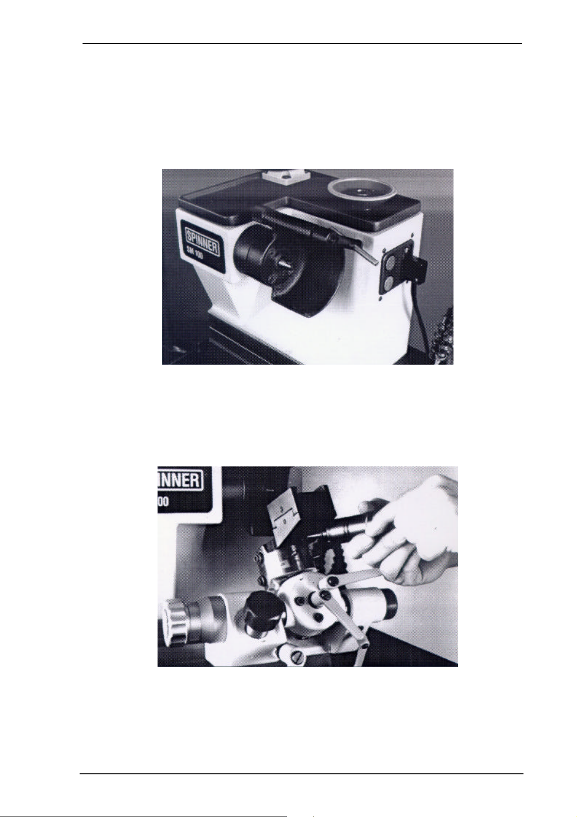
Grinding spindle:
The cone of the grinding spindle must always be kept clean. Cleaning should be carried
out with each grinding wheel change.
Grinding wheel flange:
The inner cone of the flange must always be kept clean. Cleaning should be carried out
with each grinding wheel change.
Figure 6-1: Maintenance instructions for the grinding spindle
Greasing the swivel holder:
A central lubrication nipple is located on the swivel holder. With the use of a suitable
grease press lubrication should be carried out approx. Every week depending on demand.
For this, use a customary multi-purpose grease.
Figure 6-2: Lubricating the swivel holder
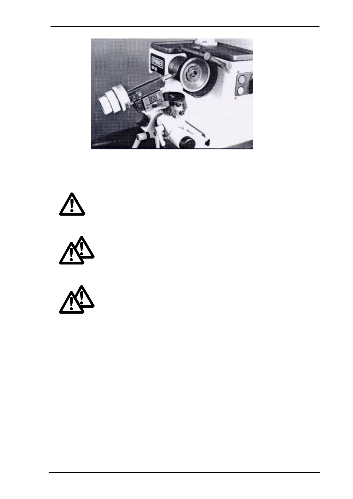
Lubricating the dividing apparatus
A central lubrication nipple is located on the dividing apparatus. With the use of a suitable
grease press, lubrication should be carried out approx. Every week depending on
demand. For this, use a customary multi-purpose grease.
SM-2-12/02
SPINNER Werkzeugmaschinenfabrik GmbH
6-2
Page 31
Maintenance instruction
Figure 6-3: Lubricating the dividing apparatus
ONLY USE ORIGINAL SPARE PARTS FROM SPINNER!
OTHERWISE WE CAN NOT ACCEPT ANY GUARANTEE CLAIMS!
WORK DONE ON THE ELECTRICAL EQUIPMENT OF THE
MACHINE MAY ONLY BE CARRIED OUT BY AN ELECTRICIAN!
THERE IS DANGER!
IF REPAIR WORK IS NECESSARY THE WORK ONLY MUST BE
DONE BY A TECHNICAL ENGINEER FROM SPINNER OR FROM
ANY OTHER COMPANY THAT IS AUTHORIZED BY SPINNER!
SM-2-12/02
SPINNER Werkzeugmaschinenfabrik GmbH
6-3
Page 32

Quick change unit for grinding wheel
Technical Product Documentation
Machine type: Tool grinder SM100
Serial number:
Version: SM-1-03/02
Valid until:
Article number: 61511E
7 Quick change unit for grinding wheel
SM-1-03/02
SPINNER Werkzeugmaschinenfabrik GmbH
7-1
Page 33
Quick change unit for grinding wheel
7.1 Quick change unit for grinding wheel
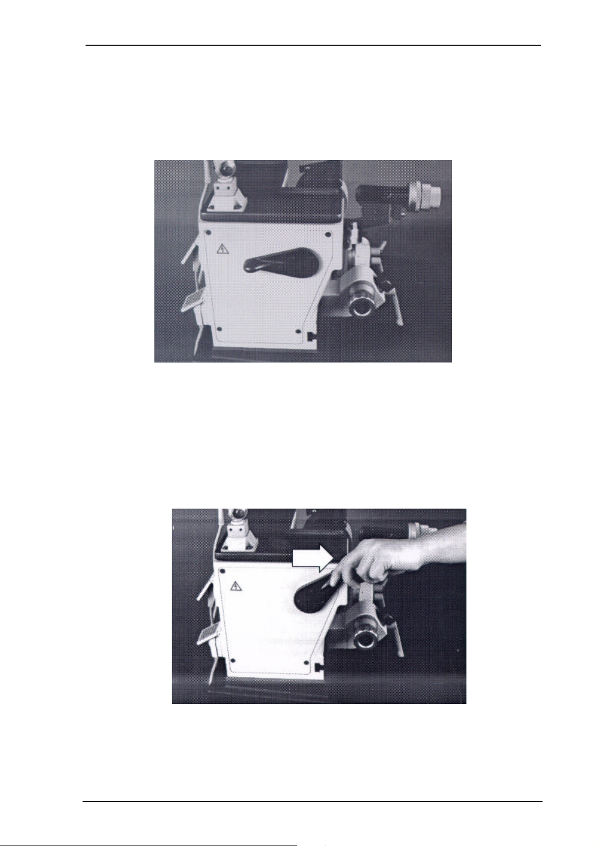
Lever “closed“:
The lever for activating the quick change unit is mounted on the left side of the machine.
The picture figures the “closed“ position. The grinding spindle is only able to start when
the lever is in this position and a grinding wheel has been properly mounted.
Figure 7-1: Quick change unit - lever “closed“
Lever “open“:
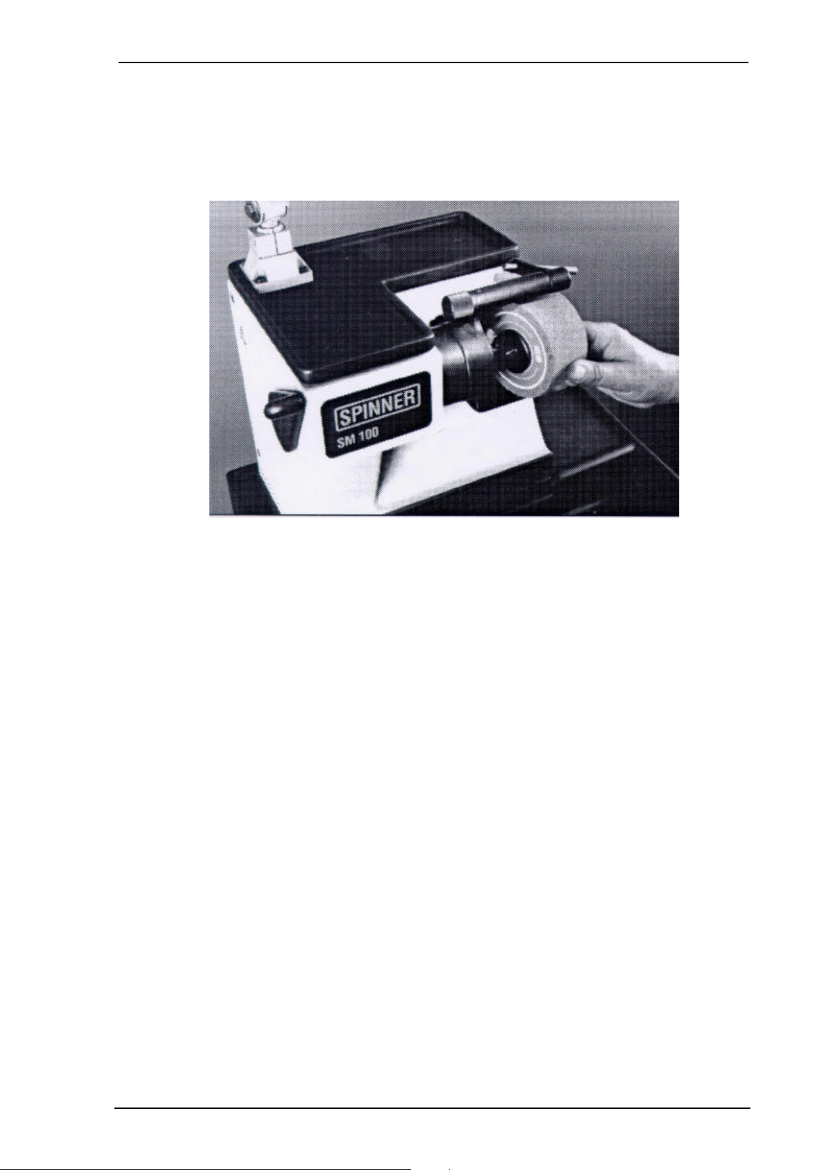
The lever is to be pulled forward up to the stopper. The grinding wheel can only be
removed when the lever is in this position. The opening of the grinding wheel locking
device when the grinding spindle is in operation causes an immediate brake and stop of
the drive motor. It is not possible to start the grinding spindle again when the lever is in
the open position.
Figure 7-2: Quick change unit - lever “open“
SM-1-03/02
SPINNER Werkzeugmaschinenfabrik GmbH
7-2
Page 34
Quick change unit for grinding wheel
Changing the grinding wheel:
Pull the lever forward and turn the grinding wheel forward by approx. 90 degrees up to the
stopper. In this position the grinding wheel can be removed in axial direction from the
mounting cone of the grinding spindle. The new grinding wheel is to be placed in axial
direction onto the cone and turned to the back by approx. 90 degrees up to the stopper.
After that, return the lever and lock the grinding wheel.
Figure 7-3: Quick change unit - changing the grinding wheel
SM-1-03/02
SPINNER Werkzeugmaschinenfabrik GmbH
7-3
Page 35

Assembly of the grinding wheel flange
Technical Product Documentation
Machine type: Tool grinder SM100
Serial number:
Version: SM-1-03/02
Valid until:
Article number: 61511E
8 Assembly of the grinding wheel flange
SM-1-03/02
SPINNER Werkzeugmaschinenfabrik GmbH
8-1
Page 36
Assembly of the grinding wheel flange
8.1 Assembly of the grinding wheel flange
CORRESPONDING TEST RUN!
WHEN ASSEMBLING THE GRINDING WHEEL BE ABSOLUTELY
SURE THAT THE GRINDING ELEMENTS ARE NOT DAMAGED! IN
ADDITION, NEW GRINDING ELEMENTS NEED A
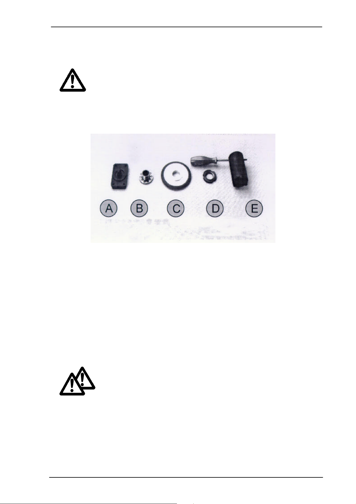
8.2 Assembly fittings
Figure 8-1: Assembly fittings
A) Holding device
B) Grinding wheel flange
C) Grinding wheel
D) Fixing nut
E) Special wrench
8.3 Assembly
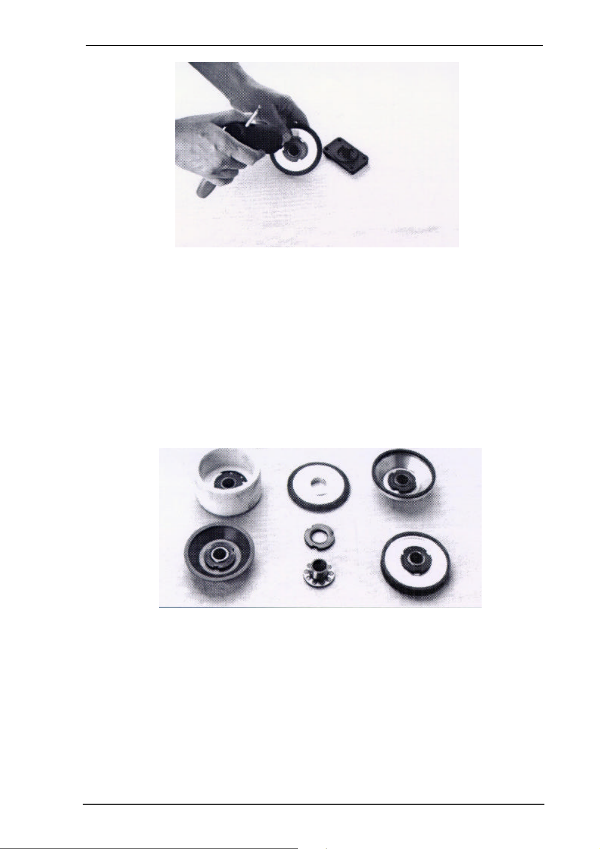
It is advisable to clamp the holding device A in a vice. Place the grinding wheel C onto the
flange B and secure using the nut D. The premounted grinding wheel is to be placed into
the holding device A along with the flange. Using the special wrench E, the flange is to be
tightened firmly onto the grinding wheel.
THERE IS DANGER IF THE FLANGE IS NOT FIRMLY
TIGHTENED!
SM-1-03/02
SPINNER Werkzeugmaschinenfabrik GmbH
8-2
Page 37
Assembly of the grinding wheel flange
Figure 8-2: Assembly
8.4 Grinding wheels
Bore diameter: 25mm
Max outer diameter: 100mm
Max. height: 50mm
Ceramic grinding wheels as well as diamond or borazon grinding wheels of many different
shapes and sizes can be used, to the extent that the above mentioned criteria is fulfilled.
Only the original grinding wheel flange may be used.
Figure 8-3: Grinding wheels
SM-1-03/02
SPINNER Werkzeugmaschinenfabrik GmbH
8-3
Page 38

Dressing the grinding wheel
Technical Product Documentation
Machine type: Tool grinder SM100
Serial number:
Version: SM-1-03/02
Valid until:
Article number: 61511E
9 Dressing the grinding wheel
SM-1-03/02
SPINNER Werkzeugmaschinenfabrik GmbH
9-1
Page 39
Dressing the grinding wheel
9.1 Operating elements
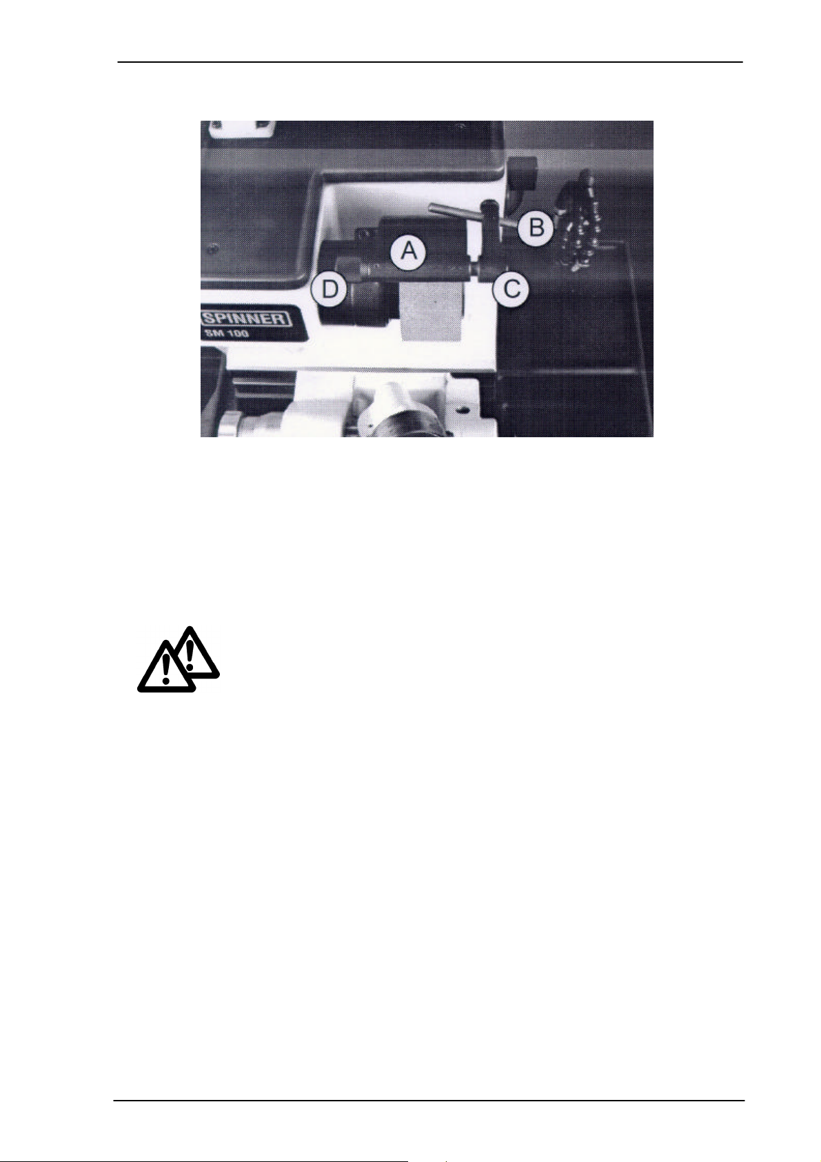
Figure 9-1: Operating elements
A) Protective hood for the grinding wheel
B) Dressing diamond
C) Swivel arm with clamp for dresser
D) Infeed screw
THE PROTECTIVE HOOD MUST ONLY BE OPENED AS FAR AS
NECESSARY WHILE DRESSING THE GRINDING WHEEL! IT
KEEPS BACK FRAGMENTS IF THE GRINDING ELEMENT IS
BREAKING! IT SERVS AS A SAFETY ELEMENT!
9.2 Handling
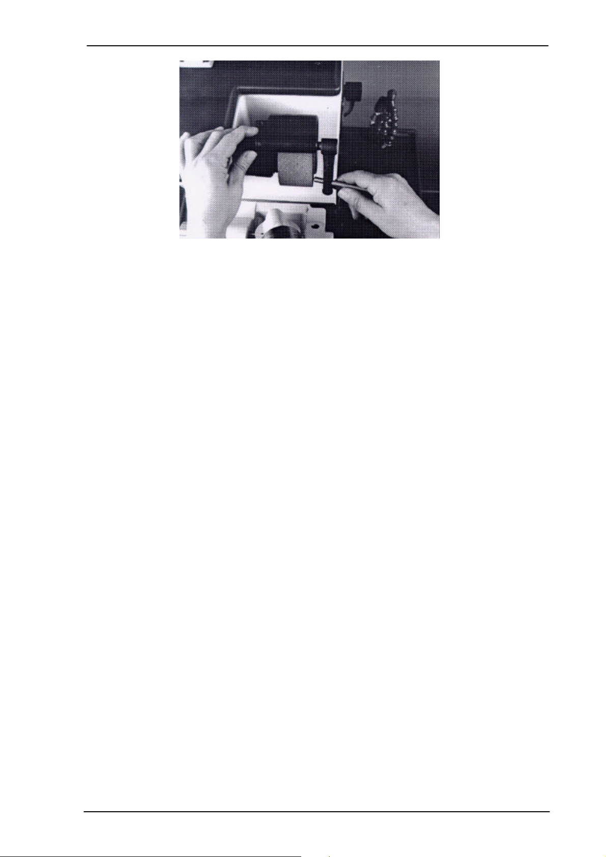
Clamp the dressing diamond in the swivel arm. Move the swivel arm downwards and by
means of the infeed screw, contact the dressing diamond to the grinding wheel. Start the
grinding spindle and slowly move the dressing diamond past the grinding wheel. If
necessary, repeat the dressing process with more infeed.
SM-1-03/02
SPINNER Werkzeugmaschinenfabrik GmbH
9-2
Page 40
Dressing the grinding wheel
Figure 9-2: Handling
SM-1-03/02
SPINNER Werkzeugmaschinenfabrik GmbH
9-3
Page 41

Universal swivel holder
Technical Product Documentation
Machine type: Tool grinder SM100
Serial number:
Version: SM-1-03/02
Valid until:
Article number: 61511E
10 Universal swivel holder
SM-1-03/02
SPINNER Werkzeugmaschinenfabrik GmbH
10-1
Page 42
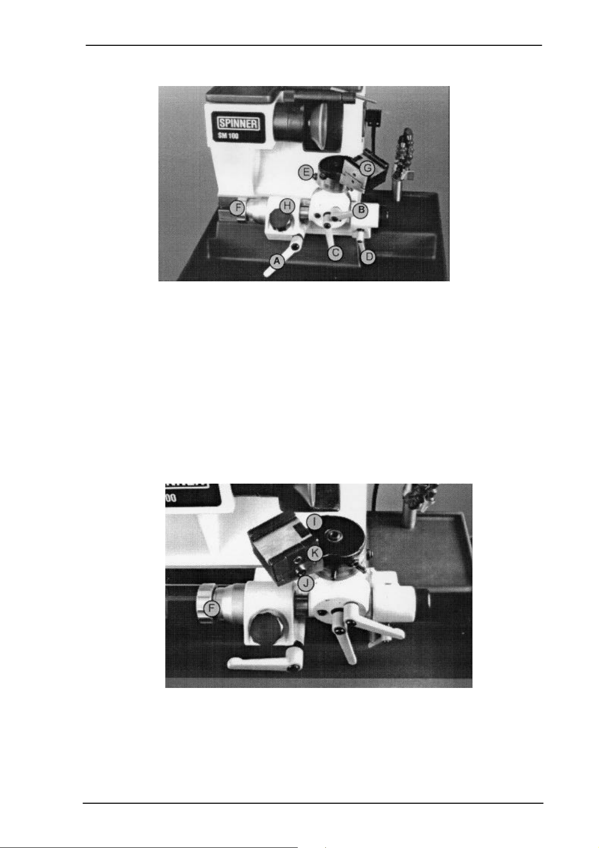
Universal swivel holder
10.1 Universal swivel holder
Figure 10-1: Clamping lever and adjusting elements
Clamping lever
A) Central mounting
B) Swivel movement
C) Rotary movement
D) Tilt and infeed movement
Adjusting elements:
E) Stopper “rotation“
F) Infeed for grinding
G) Adjustment cross table
H) Stopper tilting movement
Figure 10-2: Cross table
Cross table:
I) Clamp “Top slide“
J) Micrometer screw
K) Clamp “accessories“
SM-1-03/02
SPINNER Werkzeugmaschinenfabrik GmbH
10-2
Page 43
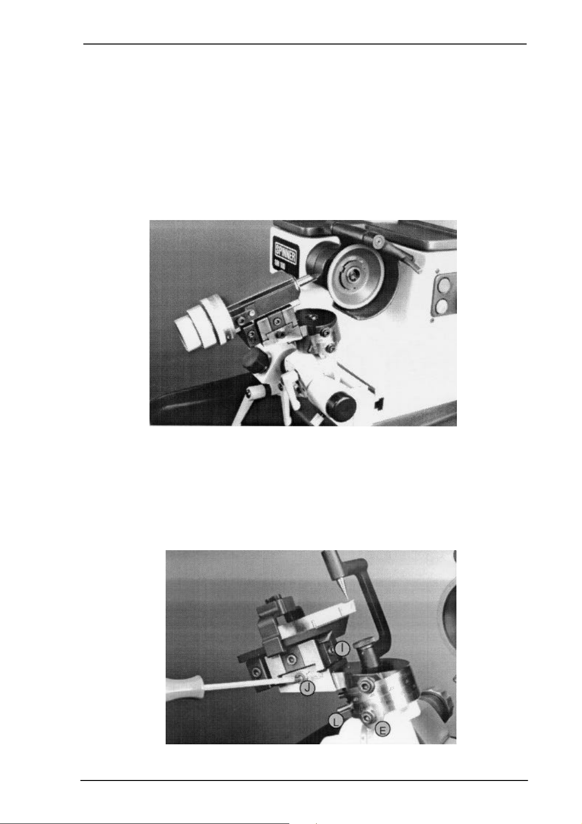
Universal swivel holder
Fine infeed F:
The scale of the fine infeed F is graduated into increments of 0,01mm. One revolution
results in an infeed of 1mm. The total range of adjustment amounts to approx. 18mm.
When adjusting the swivel holder using the handwheel F, make sure that the clamp D is
always open.
Cross table:
The cross table serves for he mounting of various accessories., such as the dividing
apparatus. These accessories can be fastened by using the clamp K on the side. In the
front area of the cross table there is a second clamp I. This one clamps the adjustable top
slide to the foundation. This clamp must be loosened before every adjusting procedure
with the micrometer screw J.
Figure 10-3: Cross table
Fine adjustment:
The cross table is equipped with a micrometer screw J for adjustment purpose. The scale
is graduated into increments of 0.02mm. One revolution of the micrometer screw results
in a lateral shifting of the cross table by 0.5mm. The range of adjustment amounts to
20mm.
Figure 10-4: Fine adjustment
SM-1-03/02
SPINNER Werkzeugmaschinenfabrik GmbH
10-3
Page 44
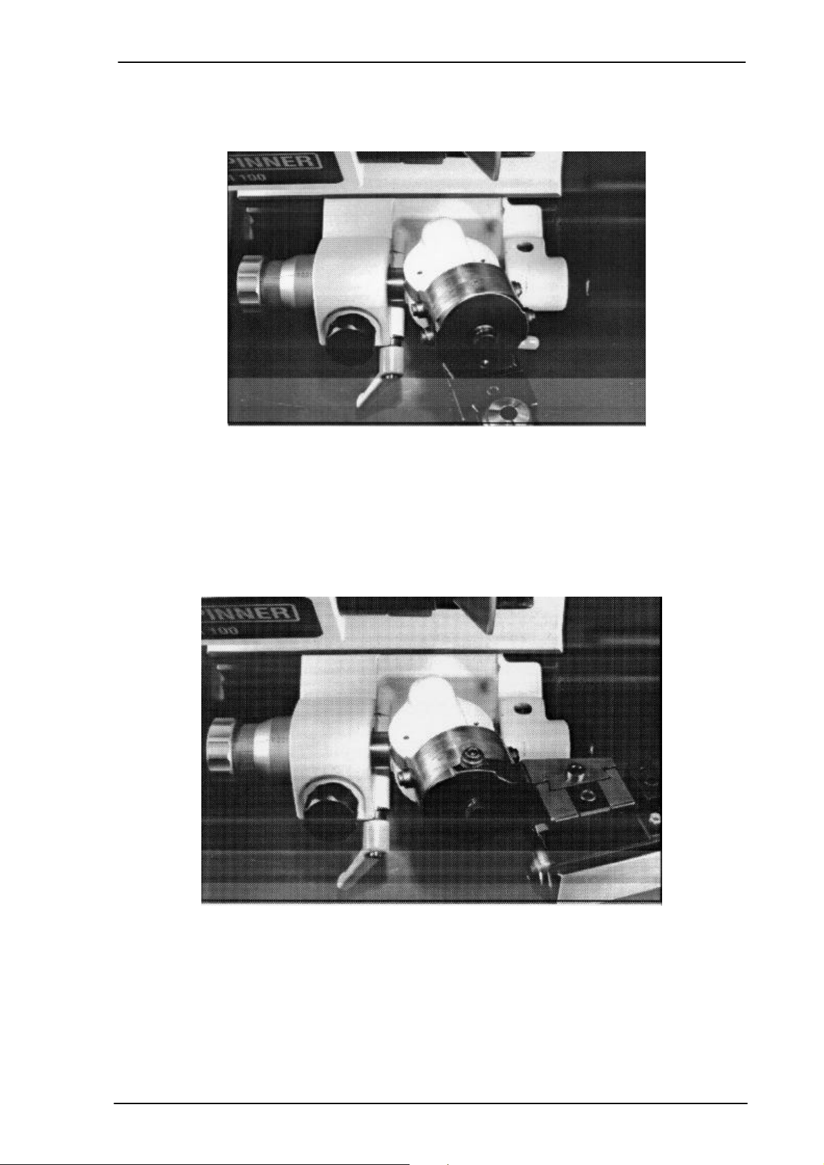
Universal swivel holder
Swivel movement:
To adjust the turning angle the stoppers E are opened. Now, using the levers L, the two
adjustment scales can be set to the desired value. The stoppers E are to be tightened
once again to arrest the unit.
Figure 10-5: Swivel movement
Adjustment scale:
There are two scales for the adjustment of the angle. One graduation mark on the scale
represents two degrees. The maximum turning angle amounts to 150 degrees on each
side. Thus the universal swivel holder allows a total swivelling range around the rotary
axis of a max. 300 degrees.
Figure 10-6: Adjustment scale
SM-1-03/02
SPINNER Werkzeugmaschinenfabrik GmbH
10-4
Page 45
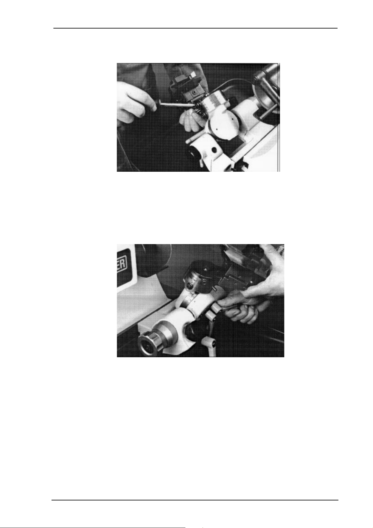
Universal swivel holder
Handling:
The picture figures how to adjust the turning angle. With the levers L the angle scale is to
be set to the correct value. After that tighten the stoppers E with the allenkey screw driver.
Figure 10-7: Handling
Adjusting the clearance angle:
To adjust the clearance angle, the lever B is to be opened and the universal swivel holder
is to be moved to the side. The scale allows for a movement of 45 degrees to each side.
One graduation mark on the scale represents two degrees of clearance angle at the
ground tool. After swivelling the lever B is to be tightened again and with this the position
is fixed.
Figure 10-8: Adjusting the clearance angle
Handling: The picture figures how to adjust the clearance angle. Using the clamping lever
B the fixing device is opened. The universal swivel holder can be swivelled to the desired
position for the clearance angle. After that, the clamping lever is to be tightened again.
SM-1-03/02
SPINNER Werkzeugmaschinenfabrik GmbH
10-5
Page 46

Dividing apparatus
Technical Product Documentation
Machine type: Tool grinder SM100
Serial number:
Version: SM-1-03/02
Valid until:
Article number: 61511E
11 Dividing apparatus
SM-1-03/02
SPINNER Werkzeugmaschinenfabrik GmbH
11-1
Page 47
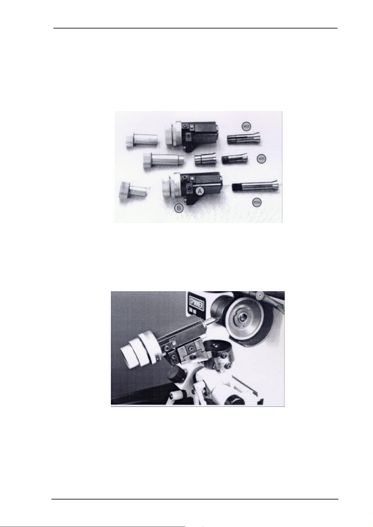
Dividing apparatus
11.1 Dividing apparatus
Two different dividing apparatus are available:
Type 1 for collet chuck W25/W20
Type 2 for collet chuck 355E
With the assistance of a reducing sleeve and a special connecting rod, the collet chuck
W20 can also be used in the dividing apparatus type 1.
Figure 11-1: Dividing apparatus
The dividing apparatus can be shifted on the swivel holder in axial direction. The roughly
adjustable stopper A serves for pre-positioning. Fine adjustments can be carried out using
the integrated micrometer screw B. The micrometer screw B has a scale of 0.02mm. One
revolution of the micrometer screw results in a position change of 0.5mm.
SM-1-03/02
Figure 11-2: Shifting the dividing apparatus
Adjusting the dividing scale:
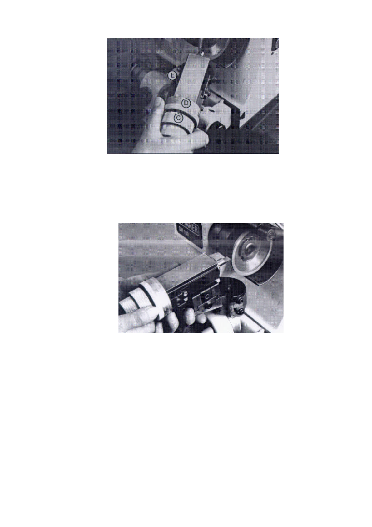
The dividing scale D is clamped by means of the hand nut C. With this, e. g. the zero
marking can be quickly brought to the desired position. The dividing scale is graduated
from 0 degree up to 360 degrees. One graduation mark represents 2 degrees. The
dividing apparatus can be mechanically locked every 30 degrees. For this purpose, a
locking bolt E is mounted on the side.
SPINNER Werkzeugmaschinenfabrik GmbH
11-2
Page 48
Dividing apparatus
Figure 11-3: Adjusting the dividing scale
Handling:
Clamp the halved cutter e. g. in the collet chuck. Loosen the dividing scale and turn the
marking to 0 degree. After that tighten the dividing scale again. Open the collet chuck and
align the cutter horizontally with the assistance of the centring bracket. Clamp the collet
chuck firmly again. The tool is now clamped and aligned.
Figure 11-4: Handling
SM-1-03/02
Indexing:
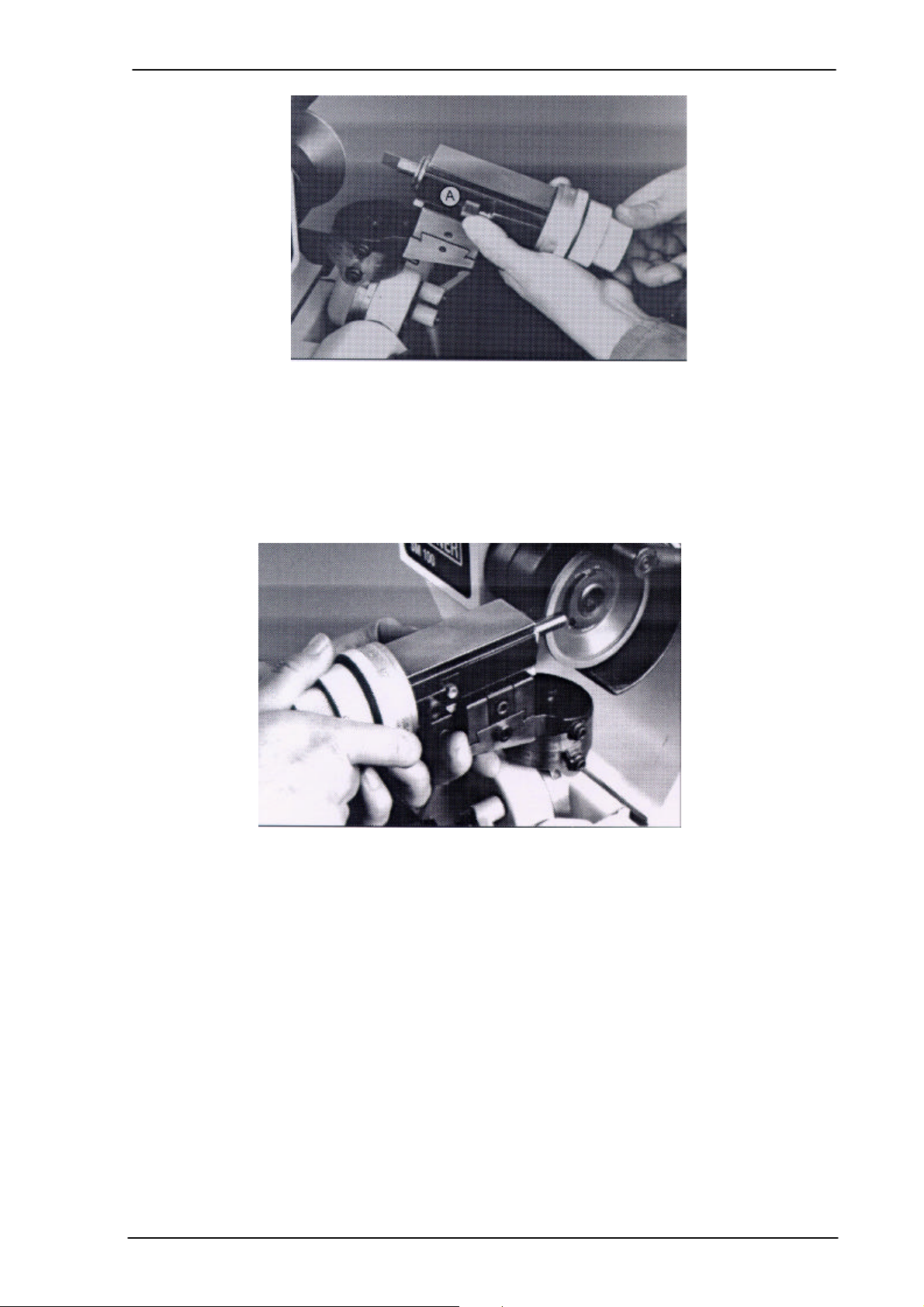
The locking bolt A can be pulled forward and turned. By pulling the locking bolt, the fixing
device of the dividing plate is disengaged and the collet chuck can be turned. After 30
degrees it can be engaged again. If the locking bolt is pulled and then turned, the
disengaged position is maintained. This is beneficial, for example, in case of cylindrical
grinding when the collet chuck should be able to turn freely.
SPINNER Werkzeugmaschinenfabrik GmbH
11-3
Page 49
Dividing apparatus
Figure 11-5: Indexing
Grinding:
As shown in the picture, the tool is turned in the dividing apparatus by 90 degrees and
then the position is fixed. Now the cutter can be ground to the center. To do this, it is
advisable to hold the dividing apparatus with both hands and to perform the grinding
process by moving back and forth.
SM-1-03/02
Figure 11-6: Grinding
SPINNER Werkzeugmaschinenfabrik GmbH
11-4
Page 50

Clamping plate for square tools
Technical Product Documentation
Machine type: Tool grinder SM100
Serial number:
Version: SM-1-03/02
Valid until:
Article number: 61511E
12 Clamping plate for square tools
SM-1-03/02
SPINNER Werkzeugmaschinenfabrik GmbH
12-1
Page 51
Clamping plate for square tools
12.1 Clamping plate for square tools
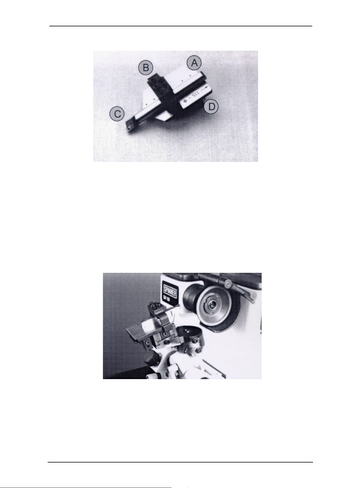
Figure 12-1: Clamping plate
Clamping plate:
A) Base plate
B) Clamping bracket
C) Tool
D) Stopper rough / fine
With the assistance of the central clamping bracket, all types of square tools can be
clamped. The maximum height of the tool can amount to 25mm. Small bore holes are
mounted in the base plate in which the cylindrical pins can be inserted. These pins serve
as lateral stoppers for positioning of the tool.
Figure 12-2: Clamping bracket of the camping plate
SM-1-03/02
SPINNER Werkzeugmaschinenfabrik GmbH
12-2
Page 52
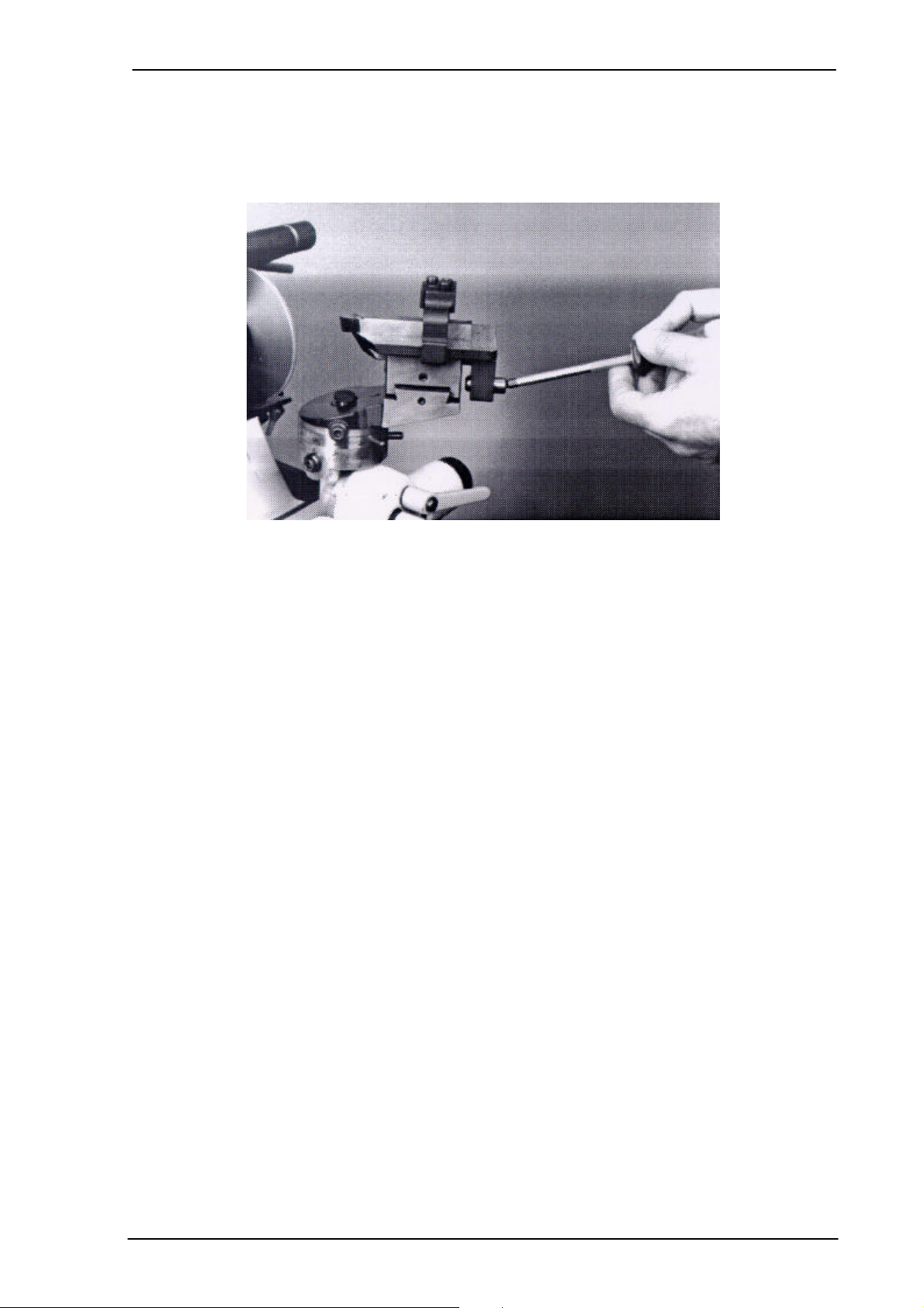
Clamping plate for square tools
Stopper:
The clamping plate can be shifted on the tool holder in horizontal direction. The roughly
adjustable stopper serves for pre-positioning. Fine adjustments can be carried out using
the integrated micrometer screw. This one has a scale of 0.02mm. One revolution of the
micrometer screw results in a position change of 0.5mm.
Figure 12-3: Stopper
SM-1-03/02
SPINNER Werkzeugmaschinenfabrik GmbH
12-3
Page 53

Grinding the radius
Technical Product Documentation
Machine type: Tool grinder SM100
Serial number:
Version: SM-1-03/02
Valid until:
Article number: 61511E
13 Grinding the radius
SM-1-03/02
SPINNER Werkzeugmaschinenfabrik GmbH
13-1
Page 54
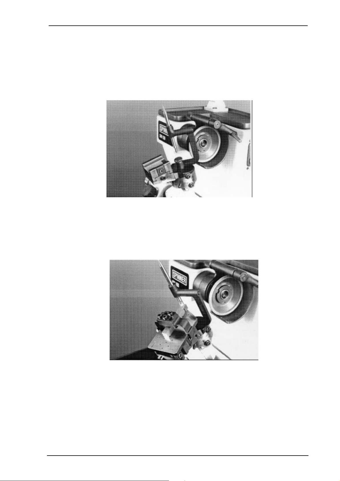
Grinding the radius
13.1 Grinding the radius
Centering bracket:
Assembly of the centering bracket is carried out by screwing it onto the rotational axis of
the universal swivel holder. To do this, the screw plug which protects the thread against
dirt must be removed. The centering bracket has a movable contacting aid. With the
assistance of the flattened side the tool can be aligned and fixed. With the assistance of
the point an adjusted radius can be optically monitored.
Figure 13-1: Centering bracket
Contacting the tool:
The front end of the tool is to be fixed to the contacting aid of the centering bracket. After
that, the rough stopper of the square clamping plate is to be positioned and fastened. The
fine stopper is to be positioned in the way that re-adjustment can be carried out about the
value of the radius.
Figure 13-2: Contacting the tool
SM-1-03/02
Contacting the tool:
The contacting aid is to be turned by 90 degrees and the tool is now to be fixed with the
side face. With this the cross table is to be shifted by means of the micrometer screw.
The left front corner of the tool is now located exactly in the rotational axis of the swivel
holder. In this position the adjusted radius has the value 0.
SPINNER Werkzeugmaschinenfabrik GmbH
13-2
Page 55
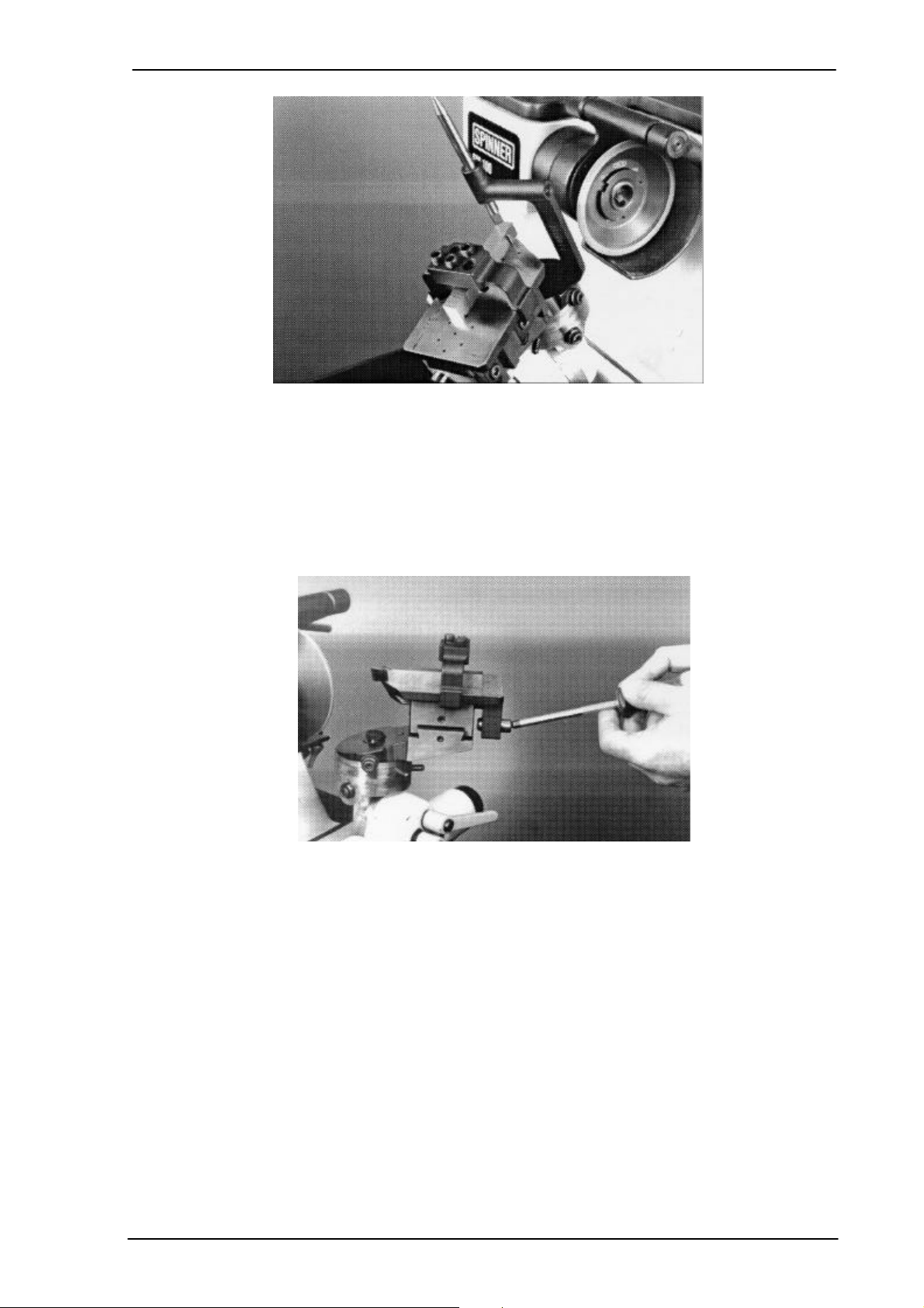
Grinding the radius
Figure 13-3: Contacting the tool
Adjusting the radius:
A radius e. g of 5mm is to be ground. To do this, the tool must be moved by 5mm to the
front and 5mm to the side. Using the micrometer screw a 5mm traverse is to be adjusted.
After that, the clamp of the clamping plate is to be loosened and shifted forward by the set
value.
SM-1-03/02
Figure 13-4: Adjusting the radius
Adjusting the radius:
In order to move the tool by 5mm to the side, the cross table is shifted with the assistance
of the micrometer screw. To do this, the clamp of the upper slide is to be loosened at first.
A 5mm traverse means turning the micrometer screw by 10 revolutions. After that, the
clamp of the upper slide is to be tightened again.
SPINNER Werkzeugmaschinenfabrik GmbH
13-3
Page 56
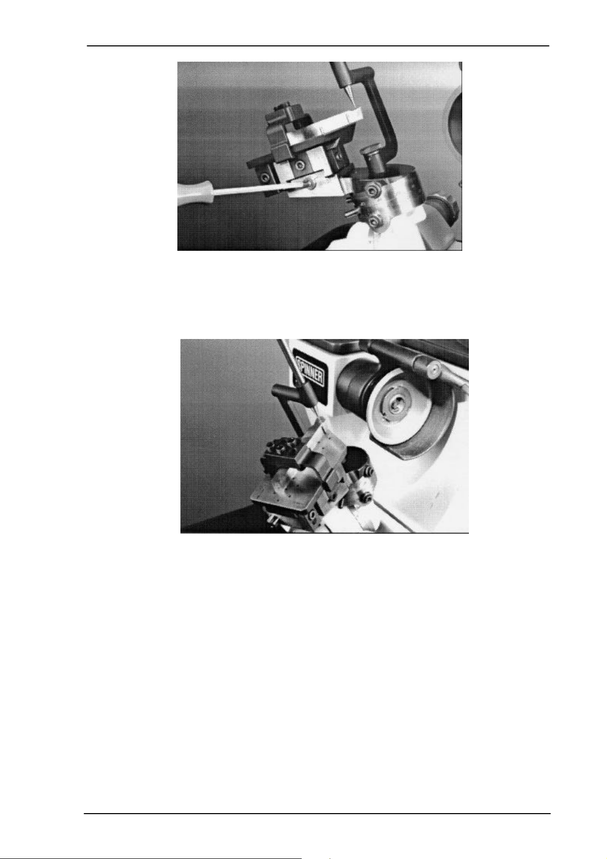
Grinding the radius
Figure 13-5: Adjusting the radius
Checking the adjustment
With the assistance of the point, the adjustment of the radius can be optically checked.
The tool is now situated in the correct position and grinding the radius can be started.
SM-1-03/02
Adjusting the clearance angle:
Before starting to grind the radius, the clearance angle of e. g. 10 degrees must be
adjusted.
SPINNER Werkzeugmaschinenfabrik GmbH
13-4
Page 57

Grinding the radius
Figure 13-6: Adjusting the clearance angle
Turning angle:
With the assistance of the stoppers and the two scales, the turning angle around the
rotational axis is to be adjusted, for example, if the tool must have a corner angle of 70
degrees. For this, a turning angle of 110 degrees must be adjusted. Scale 1 is to be set to
10 degrees and scale 2 is to be set to 110 degrees.
Figure 13-7: Turning angle
Handling:
After everything has been adjusted, you can start to grind the radius. For this, the tool
must be brought into contact with the grinding wheel. It is advisable to open the central
clamp of the universal swivel holder and to move the entire swivel holder to the correct
position. Only in this case the infeed is done by the fine adjustment.
SM-1-03/02
SPINNER Werkzeugmaschinenfabrik GmbH
13-5
Page 58
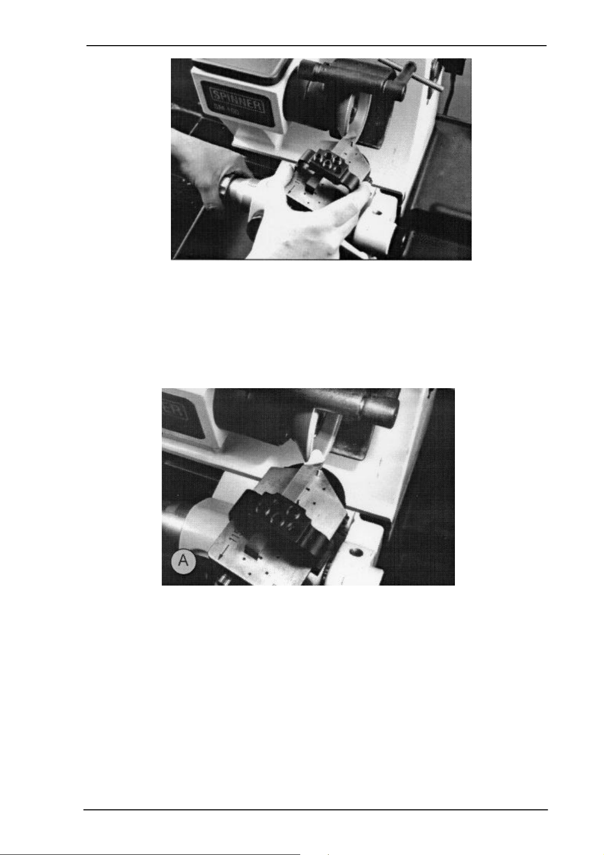
Grinding the radius
Figure 13-8: Grinding the radius
Grinding the radius:
The radius is created by swivelling the tool around the rotational axis. With the assistance
of the stopper A for the tilting movement, the position is to be set in which a continuous
rolling of the radius on the grinding wheel can be carried out. After every complete swivel
movement, in this case e. g. 110 degrees, infeed is carried out by means of the fine
adjustment and the grinding process is repeated.
SM-1-03/02
Figure 13-9: Grinding the radius
Another method to grind the radius is to separate the rotary movement and the infeed.
Clamping is carried out in the initial swivel position and a larger material fraction is ground
off. After that, the material removal process is repeated with a new turning angle . This is
continued until the entire turning angle area is covered. After that the radius grinding is
finished in one go.
SPINNER Werkzeugmaschinenfabrik GmbH
13-6
Page 59
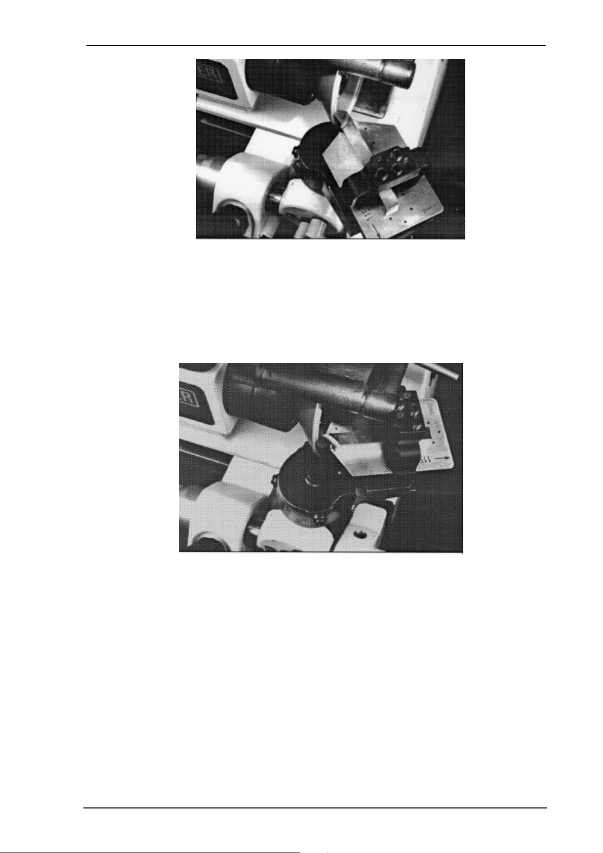
Grinding the radius
Figure 13-10: Grinding the radius
To check the gound radius the entire clamping plate can be removed from the swivel
holder. The dimension of the radius is measured under a profile projector. Using the
micrometer screws on the cross table and/or on the clamping plate, the correction value
can be set and the grinding of the radius can be finished. Different grinding wheels can be
used for pre-grinding or finishing the grinding.
SM-1-03/02
Figure 13-11: Grinding the radius
SPINNER Werkzeugmaschinenfabrik GmbH
13-7
Page 60

Grinding the cutter
Technical Product Documentation
Machine type: Tool grinder SM100
Serial number:
Version: SM-1-03/02
Valid until:
Article number: 61511E
14 Grinding the cutter
SM-1-03/02
SPINNER Werkzeugmaschinenfabrik GmbH
14-1
Page 61
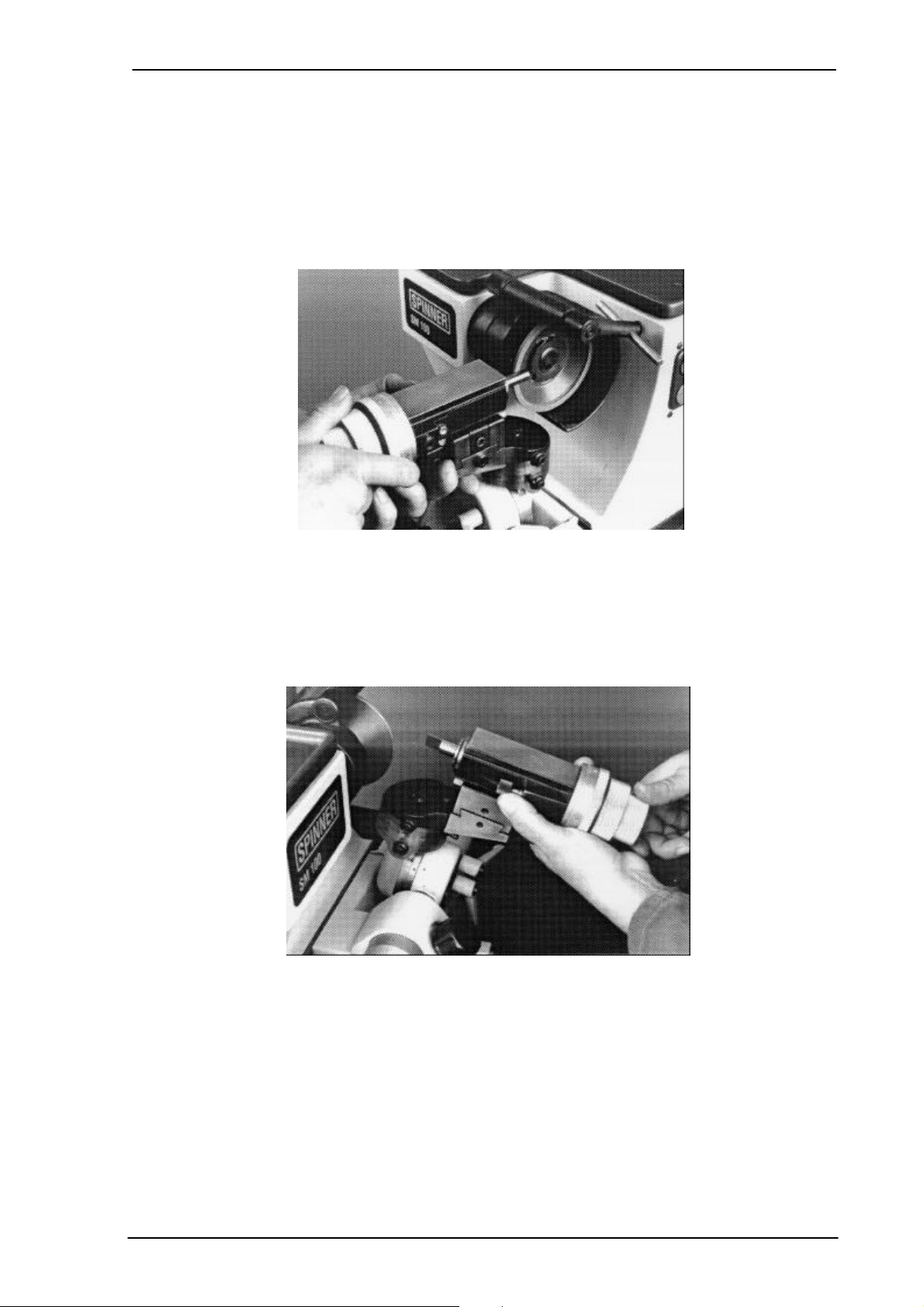
Grinding the cutter
14.1 Grinding the cutter
Halving the cutter:
At first set the graduated scale to 0 degrees. Then clamp the cutter and align it ny means
of the centering bracket. Set both turning angle scales to 0 degrees, set the stoppers and
clamp them against a rotary movement. Set the clearance angle scale to 0 degree. Bring
the cross table of the swivel holder into the central position (the surface must be flush) so
that the rotary axes of the dividing apparatus and the swivel holder intersect.
Figure 14-1: Halving the cutter
Set the dividing apparatus to 90 degrees. Make the contact to the grinding wheel. Adjust
the stopper for maximum insertion depth and start the grinding process with fine infeed.
By moving the swivel holder back and forth, material is removed by the grinding wheel.
Continue fine infeed until the cutter has been halved.
Figure 14-2: Halving the cutter
SM-1-03/02
SPINNER Werkzeugmaschinenfabrik GmbH
14-2
Page 62
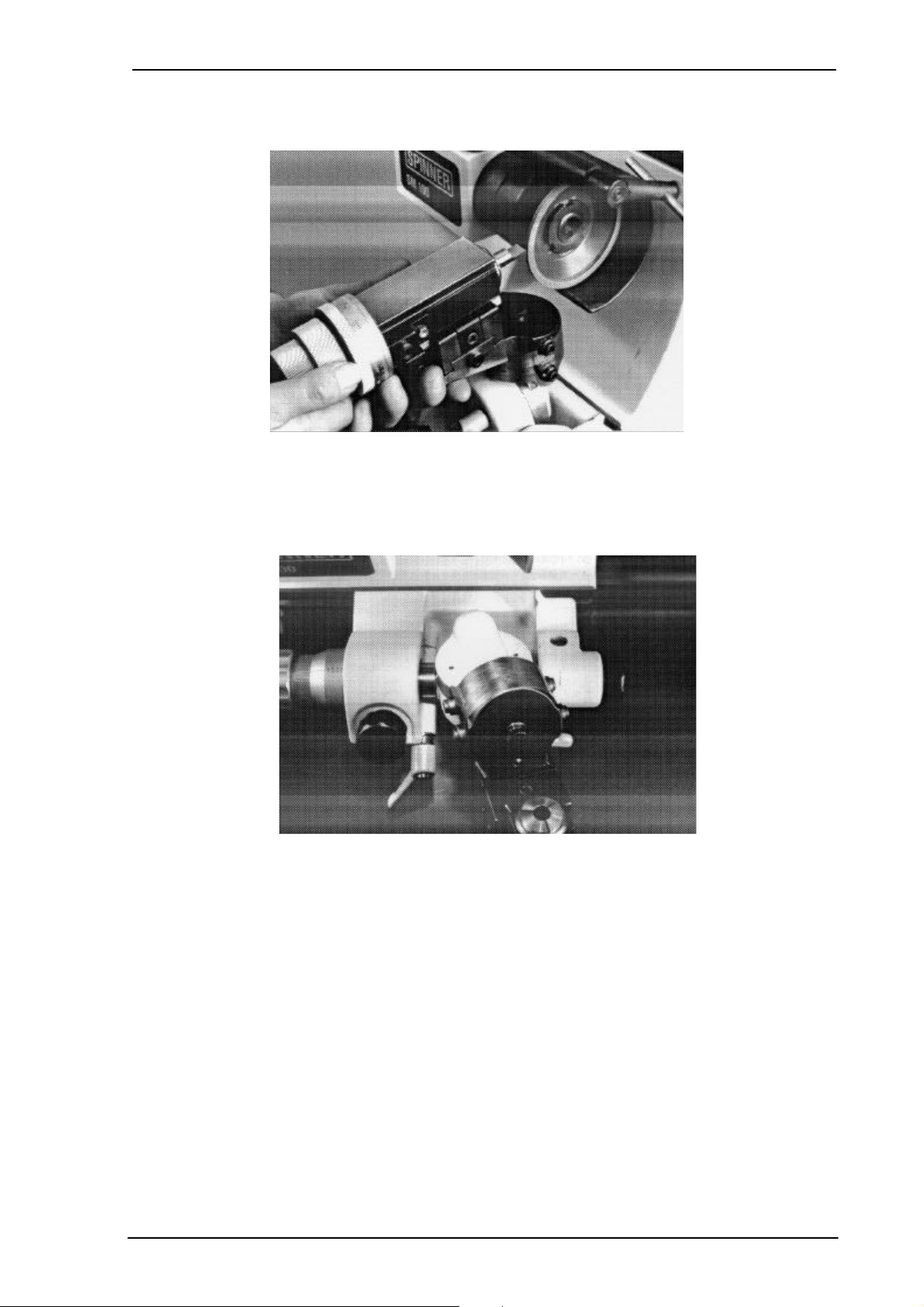
Grinding the cutter
Grinding the cutter:
After the cutter has been halved, the dividing apparatus has to be reset to the 0 degree
position. Now the actual cutter grinding can be started.
Figure 14-3: Grinding the cutter
Setting the turning angle:
You want to have a cutter with e. g. a structural tip shape with an angle of 60 degrees.
For this the scale 1 must be set to 30 degrees and the 2 stoppers must be clamped.
SM-1-03/02
Figure 14-4: Setting the turning angle
Setting the turning angle:
You want to have, for example, a cutter with a face cutting edge or a conical structure
shape, then the turning angle must also be set in the other direction. This stopper can e,
g, be set to 93 degrees. This corresponds to a clearance angle of 3 degrees at the face
cutting edge.
SPINNER Werkzeugmaschinenfabrik GmbH
14-3
Page 63
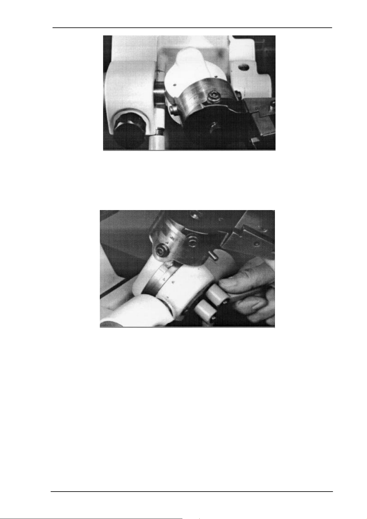
Grinding the cutter
Figure 14-5: Adjusting the turning angle
Setting the clearance angle:
Before grinding can be started, the cutting angle of the cutter must be set. The cutting
angle depends on the material e. g. between 15 and 25 degrees.
Figure 14-6: Setting the clearance angle
SM-1-03/02
Grinding the cutter:
Clamp the turning angle at 30 degrees. Adjust the stopper for the insertion depth. After
that, make contact to the grinding wheel and start the grinding process. Remove material
by means of fine infeed during which time the swivel holder is to be moved back and
forth.
SPINNER Werkzeugmaschinenfabrik GmbH
14-4
Page 64
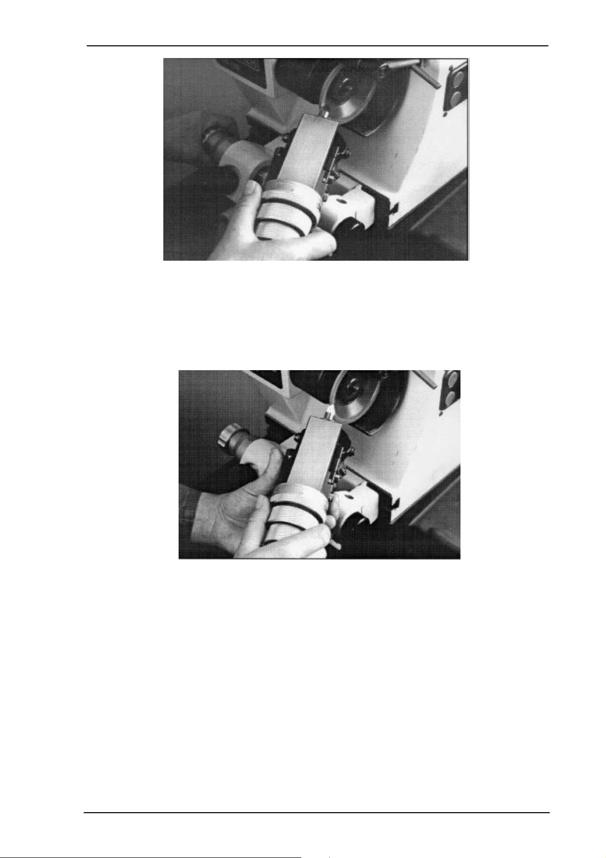
Grinding the cutter
Figure 14-7: Grinding the cutter
Grinding the cutter:
Open the locking bolt of the dividing apparatus and turn the collet chuck. Repeat the
grinding process again in this position. Move back and forth continuously in order to
remove material. Continue step by step by gradually turning on the clamping chuck.
SM-1-03/02
Figure 14-8: Grinding the cutter
Handling:
The picture figures the procedure of grinding a cutter with a pointed structural shape. It is
advisable to hold the dividing apparatus with both hands in order to carry out the grinding
process. The left hand carries out the back and forth movement for grinding while the
right hand carries out the rotary movement.
SPINNER Werkzeugmaschinenfabrik GmbH
14-5
Page 65
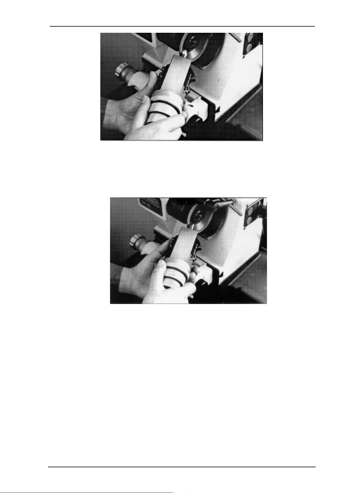
Grinding the cutter
Figure 14-9: Handling
Grinding the cutter relief:
The grinding of a relief of a milling cutter is carried out by uniformly turning the collet
chuck over the entire rotary range and infeed by the fine adjustment screw of the swivel
holder. This automatically carries out relief grinding.
Figure 14-10: Grinding the cutter relief
SM-1-03/02
When the grinding of the relief has been finished make sure that, when the dividing
apparatus turns back, the cutting edge of the milling cutter is not damaged. This could
happen if the dividing apparatus is turned too far. The scale of the dividing apparatus
indicates the current position.
SPINNER Werkzeugmaschinenfabrik GmbH
14-6
Page 66
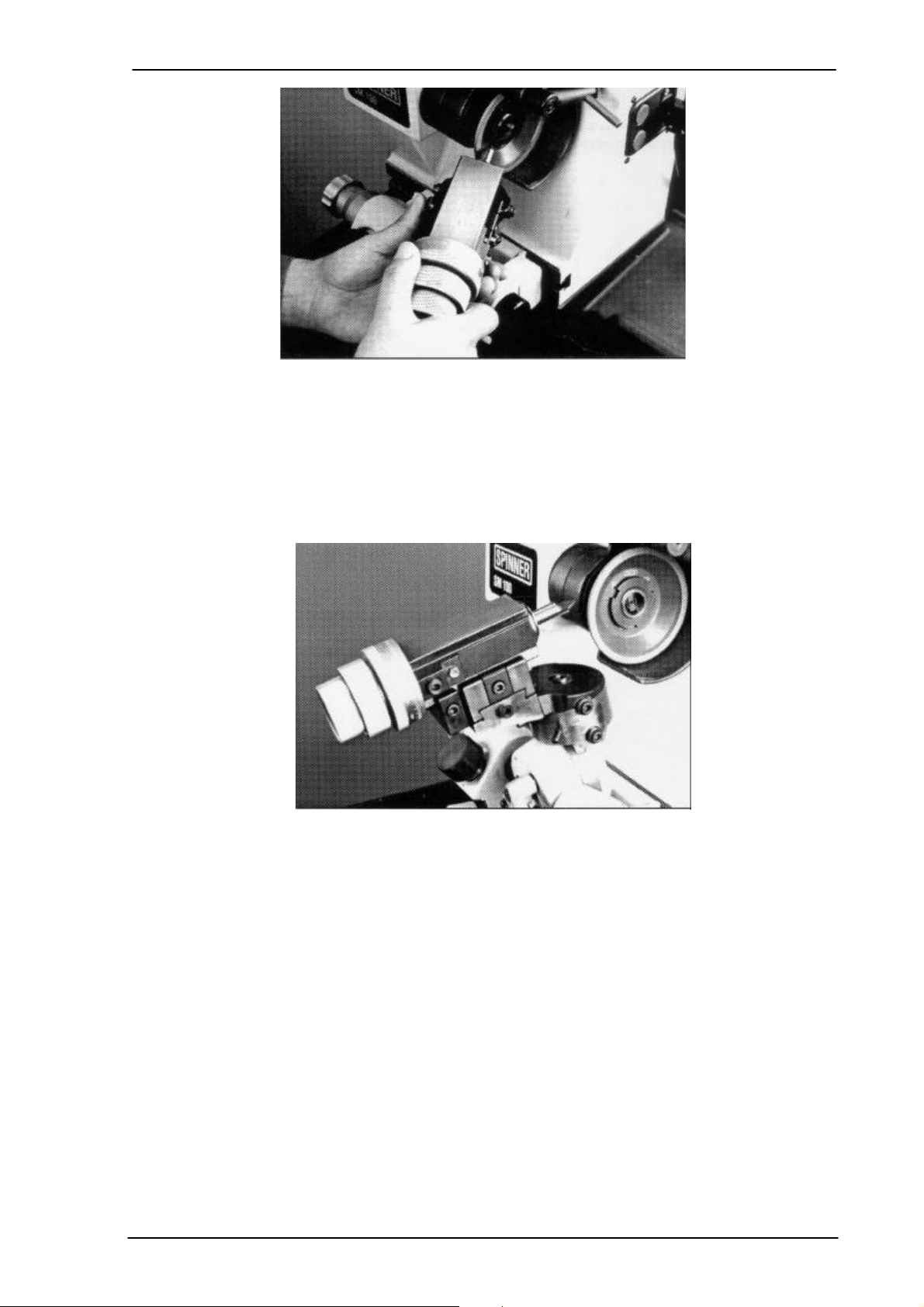
Grinding the cutter
Figure 14-11: Grinding the cutter relief
Milling cutter:
Almost all optional shapes of milling and engraving cutters can be produced. Cylindrical,
pointed or conical structural shapes, front and side cutting edges as well as rounded
shapes can be easily and quickly ground. The quick change unit for the grinding wheel
offers the possibility of being able to use the optimal grinding wheel for every case of
application.
Figure 14-12: Milling cutter
SM-1-03/02
SPINNER Werkzeugmaschinenfabrik GmbH
14-7
Page 67

Coolant unit
Technical Product Documentation
Machine type: Tool grinder SM100
Serial number:
Version: SM-2-12/02
Valid until:
Article number: 61511E
15 Coolant unit
SM-2-12/02
SPINNER Werkzeugmaschinenfabrik GmbH
15-1
Page 68
Coolant unit
15.1 Coolant unit
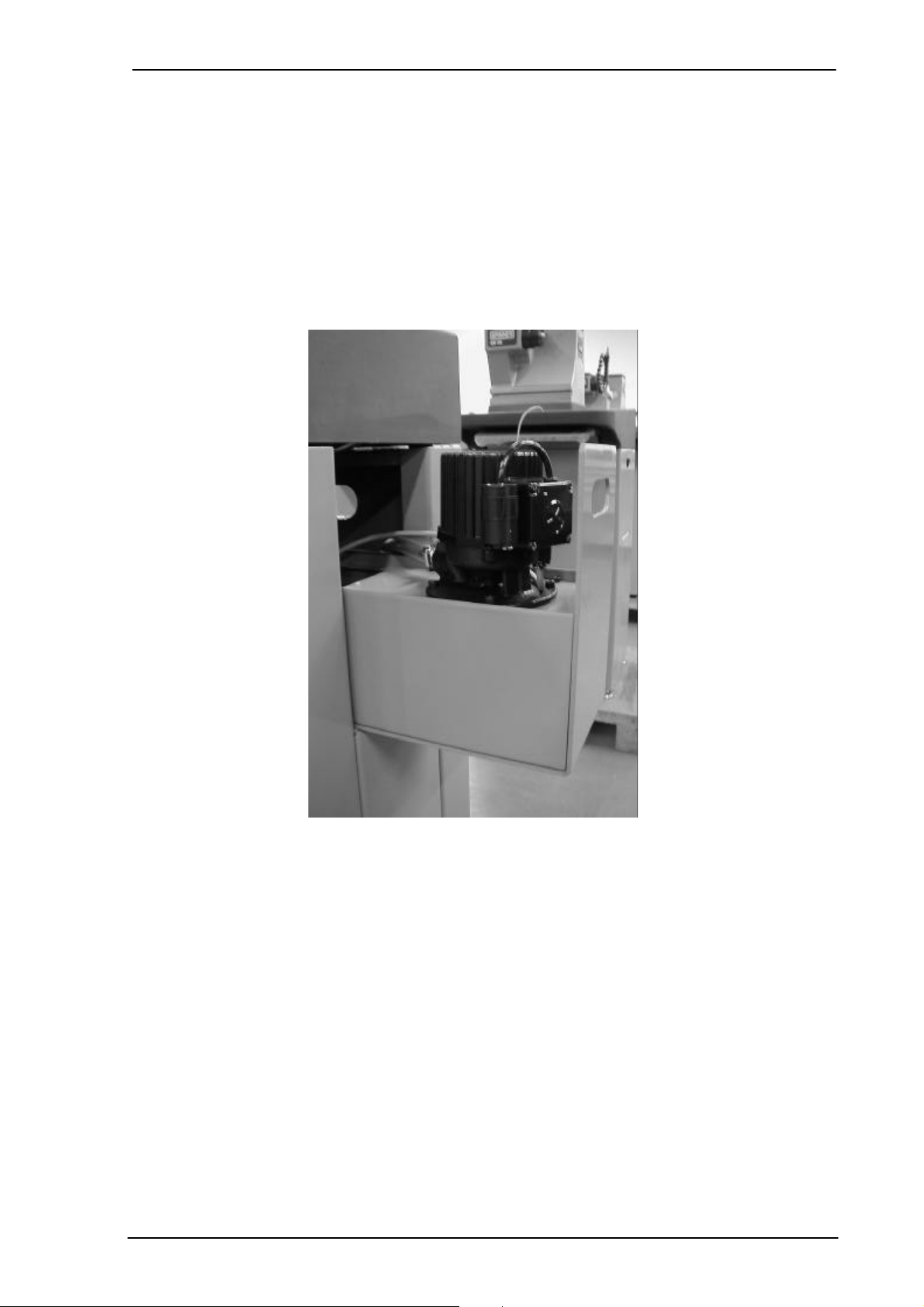
The coolant pump and the coolant tank are integrated into the base of the machine. Only
emulsions based on water may be used. The coolant system may not be operated with
flammable liquids under any circumstances. The tank must be pulled out of the base for
the purpose of checking the level. The maximum filling quantity amounts to approx. 7
liters. The coolant pump is electrically connected in the way that it can only be started
together with the grinding spindle.
A splash guard which is located beneath the pan can be attached to the edge of the pan
and offers the operator protection during wet grinding.
Figure 15-1: Coolant unit
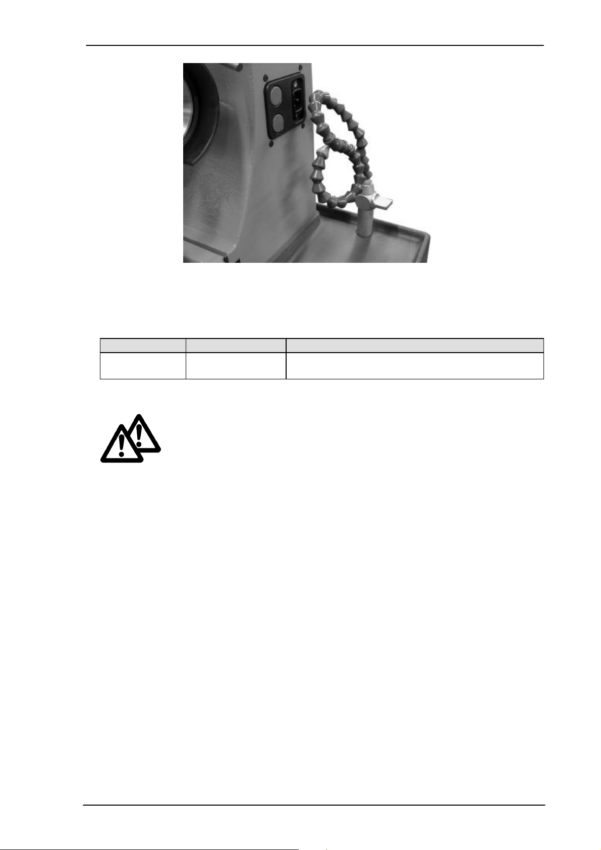
A flexible plastic hose serves as the supply line for the cooling liquid. A ball-type spigot
serves to regulate the coolant flow and to shutt off the line. There are drain holes in the
machine pan which are connected to the coolant tank via a return line.
SM-2-12/02
SPINNER Werkzeugmaschinenfabrik GmbH
15-2
Page 69
Coolant unit
Figure 15-2: Coolant hose
15.1.1 Recommended coolant
Supplier Coolant Type of lubricant
ACMOS ACMOSIT 64-20 Emulsion (water) (general use)
Concentration 2,5%
IT IS ABSOLUTELY NECESSARY TO MIND THE DATA SHEET
OF THE USED COOLANT!
SM-2-12/02
SPINNER Werkzeugmaschinenfabrik GmbH
15-3
Page 70

Accessories
Technical Product Documentation
Machine type: Tool grinder SM100
Serial number:
Version: SM-2-12/02
Valid until:
Article number: 61511E
16 Accessories
SM-2-12/02
SPINNER Werkzeugmaschinenfabrik GmbH
16-1
Page 71
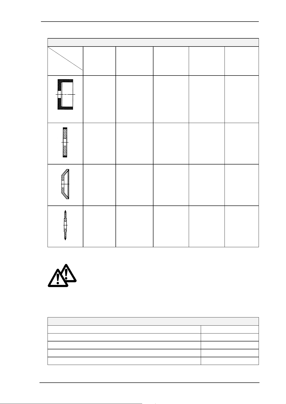
Accessories
16.1 Accessories
CONCERNING THE SAFETY MUST BE OBSERVED!
Grinding wheels
Material
Corundum Siliconcarbide Borazon Diamond
Form
Dorfnerwerk
100x50x25
Recess 84x4
Rotations
max. 6100 rpm
No. 10015
Dorfnerwerk
100x50x25
Recess 84x4
Rotations
max. 6100 rpm
Speed
32 m/s
- - -
- - No. 10410
- - -
Speed
32 m/s
No. 10016
Diamond
rough
- - -
Vollstädt Diamant
100x14x5x25
Rotations
3820-6690 rpm
Speed
20-35 m/s
No. 10019
Vollstädt Diamant
100x6x3x23
Rotations
2870-6690 rpm
Speed
15-35 m/s
No.:10017
Vollstädt Diamant
100x6x5x60°x25
Rotations
3820-5730 rpm
Speed
20-30 m/s
No. 10021
fine
Vollstädt Diamant
100x14x5x25
Rotations
3820-6690 rpm
Speed
20-35 m/s
Artnr.:10020
Vollstädt Diamant
100x6x3x23
Rotations
2870-6690 rpm
Speed
15-35 m/s
No.:10018
Vollstädt Diamant
100x6x5x60°x25
Rotations
3820-5730 rpm
Speed
20-30 m/s
No. 10022
WHEN YOU ARE BYING GRINDING WHEELS FROM OTHER
MANUFACTURERS MAKE SURE THAT THEY ARE MARKED
ACCORDING TO EN12413 OR EN13236! THE GRINDING
WHEELS MUST FULFILL THE ABOVE MENTIONED
CONDITIONS! THE DEMANDS IN THESE STANDARDS
OTHERS
Collet type W20, 1.0< Ø<20.0mm, 0.5mm increasing Art.-No 10012+Ø
Collet type W25, 1.0< Ø <25.0mm, 0.5mm increasing Art.-No 10010+ Ø
Collet type W355E, 1.0< Ø<20.0mm, 0.5mm increasing Art.-No 10008+ Ø
Dressing diamond for ceramic wheels Art.-No 10013
Grinding wheel flange for quick change unit Art.-No 10014
SM-2-12/02
SPINNER Werkzeugmaschinenfabrik GmbH
16-2
Page 72

Accessories
16.2 Other accessories (if not delivered with the machine)
ACCESSORIES FROM SPINNER!
1) Grinding wheel flange
2) Grinding wheels in form T/I/II/III
3) Dressing diamond
4) Support for the hands (all-round adjustable)
5) Swivel holder with cross slide
6) Support for square tools with clamp
7) Dividing apparatus for collets 355E up to 17,5mm
8) Dividing apparatus for collets W25 up to 25mm or with reducing for collets
W20 up to 20mm
9) Single collets or sets
10) Collets with special design
11) Inserts W25 with MK1/2/3
12) Special clamping device
The table machine can be extended with:
1) Base SM100
2) Tank with coolant supply
ONLY USE ORIGINAL REPLACEMENT PARTS AND
SM-2-12/02
SPINNER Werkzeugmaschinenfabrik GmbH
16-3
Page 73

Circuit diagram
Technical Product Documentation
Machine type: Tool grinder SM100
Serial number:
Version: SM-1-03/02
Valid until:
Article number: 61511E
17 Circuit diagram
SM-1-03/02
SPINNER Werkzeugmaschinenfabrik GmbH
17-1
Page 74
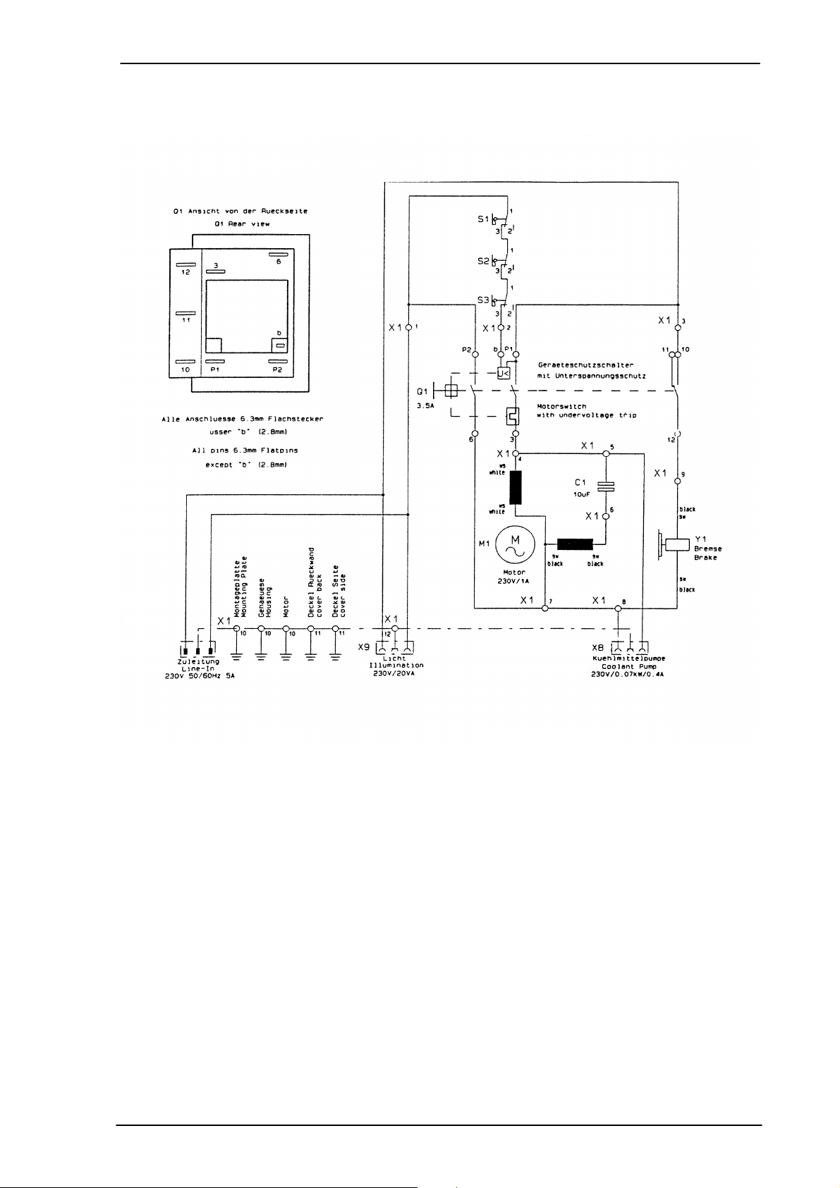
Circuit diagram
17.1 Circuit diagram
SM-1-03/02
SPINNER Werkzeugmaschinenfabrik GmbH
17-2
Page 75

Microscope
Technical Product Documentation
Machine type: Tool grinder SM100
Serial number:
Version: SM-1-03/02
Valid until:
Article number: 61511E
18 Microscope
SM-1-03/02
SPINNER Werkzeugmaschinenfabrik GmbH
18-1
Page 76
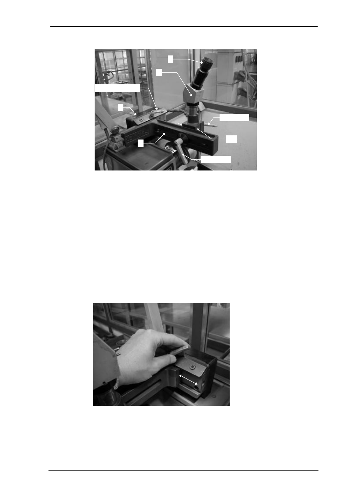
Microscope
18.1 Mikroskope
A
B with lever 3
C
D lever 2
D leverl 1
D
E
F
Figure 18-1: Microscope
Elements of the microscope:
A) Attaching block on the motor housing of Polyamid.
B) Attaching rail with lever 3 for the axial adjustment of the microscope
C) Rail for the radial adjustment of the microscope
D) Microscope support with 2 fixing levers
E) for radial adjustment
F) for the adjustment of height
G) Microscope unit
H) Adjustment ring
18.1.1 Axial adjustment of the microscope
Figure 18-2: Axial adjustment of the microscope
For the optical viewing of the tool the microscope unit (components C, D, E) is inserted
into the fixing rail B and is shifted to the right and left until the edge of the tool can be
seen in the reticule of the microscope.
Once the right position is reached the unit is attached by means of the lever 3.
SM-1-03/02
SPINNER Werkzeugmaschinenfabrik GmbH
18-2
Page 77
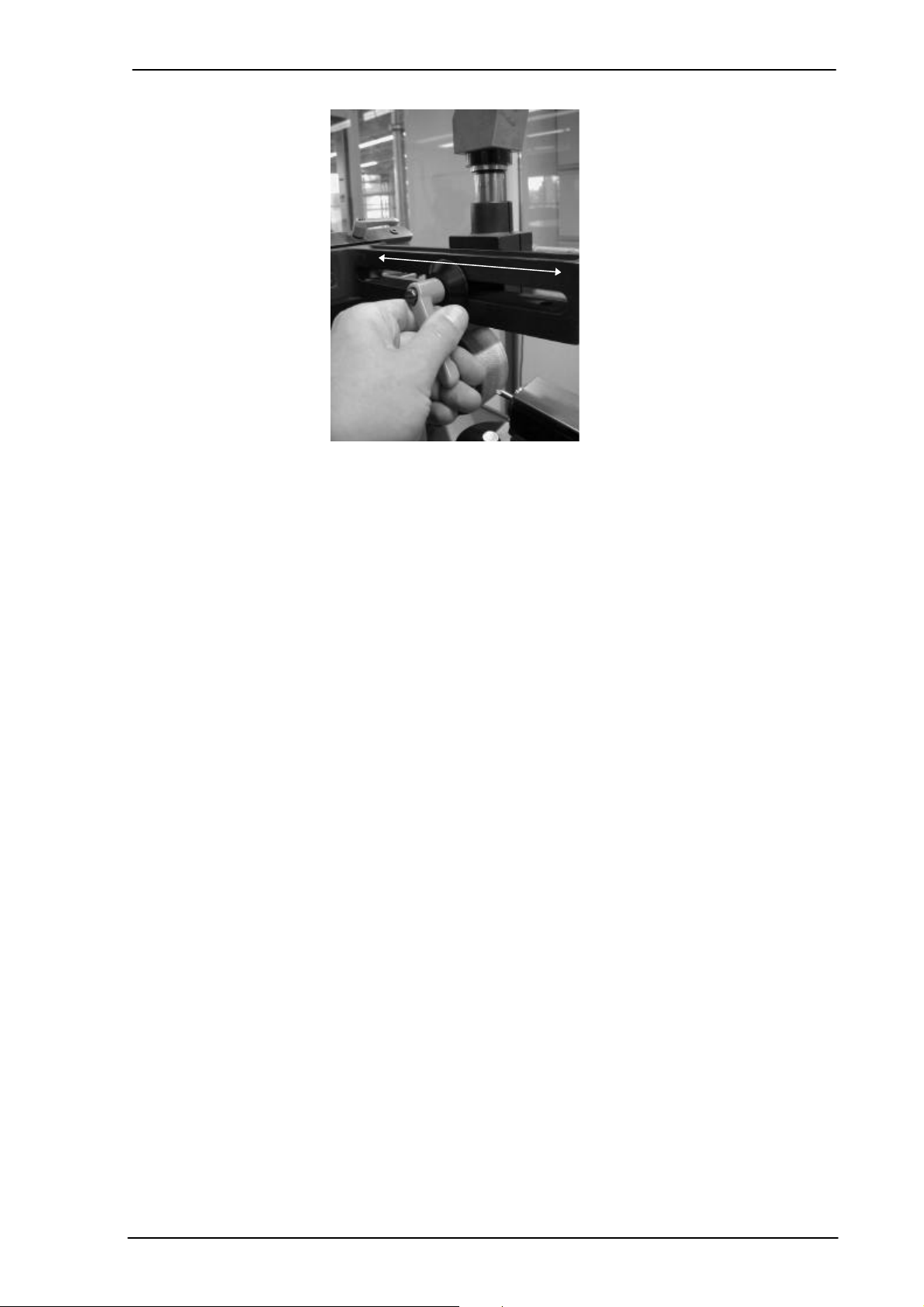
Microscope
18.1.2 Radial adjustment of the microscope
Figure 18-3: Radial adjustment of the microscope
For the radial adjustment the microscope is shifted back and forth on the support D until
the edge of the tool can be seen in the reticule of the microscope.
Once the right position is reached the unit is attached by means of the lever 1.
The adjustment of the height of the microscope unit E is done by releasing lever 2 and
then by shifting the microscope unit E up or down.
The view is focused by turning the black adjustment ring F of the microscope unit E.
SM-1-03/02
SPINNER Werkzeugmaschinenfabrik GmbH
18-3
 Loading...