

Spinlock CTC, XXC Clutch, XX0812, ZS Alloy, ZS Carbon Instruction Booklet
...
The perfect way to hold very high loads on new high-tech low stretch ropes;
safely, permanently and without rope wear.
XX0812
XX0812/L
XX0812/S
XX0812/LS
XX0812/HS
XX Clutch
XX0812/HP
XXB0812
XXB0812/L
XXC0812/S
XXC0812/LS
XXC0812/HS
XXB ClutchZS Jammer
XXC0812/HP
XXC0812
XXC0812/HP
XXC0812/HS
XXC0812/HBP
XXC0812/HBS
XXC Clutch
Alloy
ZS0810
ZS1214
ZS1618
XX powerclutch for 8-12 mm lines
lock open version XX powerclutch
silver anodised XX powerclutch
lock open version XX powerclutch silver anodised
XX powerclutch for side mounting starboard
XX powerclutch for side mounting port
XXB powerclutch with ceramic jaws
lock open version XXB powerclutch
silver anodised XXB powerclutch
lock open version XXB powerclutch silver anodised
XXB powerclutch for side mounting starboard
XXB powerclutch for side mounting port
CTiC Series, Black
CTiC Series bolted port sidemount, Black
CTiC Series bolted starboard sidemount, Black
CTiC Series bonded port sidemount, Black
CTiC Series bonded starboard sidemount, Black
Carbon
ZS1014C
ZS1014B
supplied ready for bonding
ZS1618C
ZS1618B
supplied ready for bonding
ZS1824C
ZS2632C
ZS0810/OPEN
ZS1014/OPEN
ZS1418/OPEN
ZS1824/OPEN
Jammer
ZS2632/OPEN
ZS Open
8-10 mm lines
10-14 mm lines
14-18 mm lines
18-24 mm lines
26-32 mm lines
3R308A/5

Contents
page no. page no.
Introduction 4
Performance 5-7
ZS Alloy Jammers and ZS Carbon Jammers
How to use 8-9
Installation 16
Maintenance 22-23
ZS Open Jammers
How to use 10-11
Installation 17
Maintenance 22-23
ZS Remote Lock Back Switch
How to use 12-13
Installation 18-19
XX Clutches
How to use 14-15
Installation 20-21
Maintenance 24-27
Options for the XX0812 range
English
Handle Assembly Replacement XX-HDLB 28-29
Handle Assembly Replacement XXC-HDLB 30-31
Converting XX0812 to XX0812/L lock open version 32-33
XX / XXC0812 side mounting 34
ZS and XX Custom Options 35
ZS and XX Range Spares 36-37
RP25 rope treatment 38
Special Projects Team and customer support 39-40
Introduction 42
Performance 43-45
Mode d’emploi
Coinceurs ZS Alloy et ZS Carbon 46-47
Coinceurs ZS Open 48-49
Commutateur de verrouillage arrière ZS–RLB à distance 50-51
Bloquers XXC0812, XX0812, XX0812/L 52-53
Installation
Coinceurs ZS Alloy 54
Coinceurs ZS Carbon 55
Commutateur de verrouillage arrière ZS–RLB à distance 56-57
Bloquers XXC0812, XX0812, XX0812/L 58-59
Français
Entretien
Coinceurs ZS Alloy, Carbon et Open 60-61
Bloquers XXC0812, XX0812, XX0812/L 62-65
Options pour le serie XX0812
Remplacement du mécanisme d’assemblage de la poignée XX0812-HDLB 66-67
Remplacement du mécanisme d’assemblage de la poignée XXC0812-HDLB 68-69
Transformer le bloqueur XX0812 en Open XX0812/L 70-71
Fixation latérale XX / XXC0812 72
Options sur-mesure ZS et XX 73
Pièces détachées ZS, XXC et XX 74-75
Système de mesure de charges ZS Ropesense 76-76
Traitement des cordages RP25 87
Special Projects Team et service client 88
2 3
www.spinlock.co.uk

Introduction Performance
Spinlock are the experts in high load rope holding. These high load models
are designed to match the advances in high strength ropes. With their unique
wedge action they will hold expensive sheets and halyards safely and securely,
with low risk of damage.
Products in the high load range include the ZS Alloy, ZS Carbon, ZS Open
Jammers, XX, XXB and XXC Powerclutch, holding ropes from 8mm to 32mm and
loads up to 12000kg.
High Load products included in this instruction booklet include:
XX Clutch
XX0812
XX0812/L
XX0812/S
XX0812/LS
XX0812/HS
XX0812/HP
ZS1014B, ZS1618B and XXC0812/HBP/HBS are supplied designed for bonding directly onto spars,
booms and decks (see page 17).
XXB Clutch
XXB0812
XXB0812/HP
XXB0812/HS
XXB0812/L
XXB0812/S
XXB0812/LS
XXC Clutch
XXC0812
XXC0812/HP
XXC0812/HS
XXC0812/HBP
XXC0812/HBS
XXC0812/L
ZS Alloy
ZS0810
ZS1214
ZS1618
ZS Carbon
ZS1014C
ZS1014B
ZS1618C
ZS1618B
ZS1824C
ZS2632C
ZS Open
ZS0810/OPEN
ZS1014/OPEN
ZS1418/OPEN
ZS1824/OPEN
ZS2632/OPEN
Introduction
ZS1214, ZS1014C, ZS1014B, ZS1618C and ZS1618B are supplied with jaws and rear blocks
prepared for use with ‘ZS-RLB’ Remote Lock Back Switch allowing pre tensioning of the jaws for
release and remote operation of the jammer (see page 18).
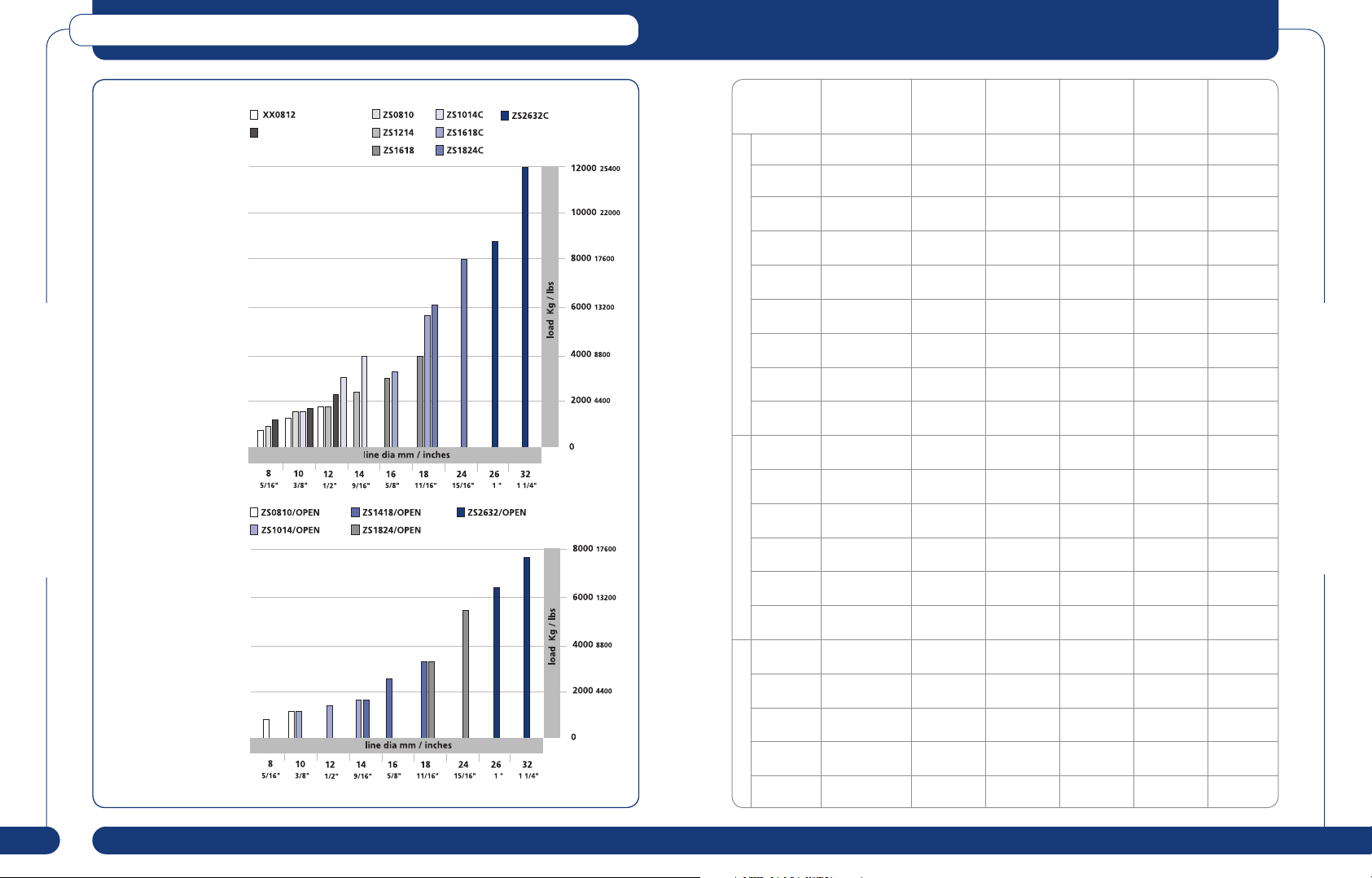
The ZS and XX range of clutches and jammers are designed to generate high compressive loads
on the rope to ensure the core bears the greater part of the load without over stressing the
polyester or other fibres of the outer braid or cover. The structure of the jammers and clutches can
withstand loads beyond the stated max holding load. The data shown, represents the maximum
safe achievable holding power we recommend for each product for a given diameter with polyester
covered ropes.
The actual load achievable can vary considerably according to the quality and construction of the
rope used. Before selecting the rope to use in the product, check:
• The actual measured diameter under load.
• Other cover blends can be successfully be held with ceramic jaw sets.
• The cover is a close fit on the core with an interface layer or fibre coating. Nominal section
should be round.
• Sleeved areas are fully pre-tensioned with smooth entry and exit tapering.
• The load rating for the rope and safety factor recommended by the rope manufacturer.
Recent development in rope manufacture has centred on the use of blended covers, where
high tech fibres such as Aramid, Technora, Dyneema or Vectran are co-braided with polyester or
polypropylene. Whilst hardwearing, with a high degree of heat resistance, these covers can be
harder to hold in clutches or jammers compared to polyester covered lines. See Page 36 or contact
the Special Projects Team for advice on custom jaw surfaces to suit specific blended covers,
including high line speed protection.
Performance
4 5
www.spinlock.co.uk
Performance
XXC0812 / XXB0812
Jammer & Clutch
Max Safe Working
Loads
Performance
Open Jammer
Safe Working Loads
Model Line Dia Maximum
XX0812 8-12mm
XXB0812 8-12mm
XX0812
/HP & /HS
ZS0810 8-10mm
ZS1214 12-14mm
AlloyCarbonOpen/Mobile
XXC0812 8-12mm
XXC0812
/HP & /HS
XXC0812
/HBP & /HBS
ZS1618 16-18mm
ZS1014C 10-14mm
ZS1014B
Bonded
ZS1618C 16-18mm
ZS1618B
Bonded
ZS1824C 18-24mm
ZS2632C 26-32mm
ZS0810/
OPEN
ZS1014/
OPEN
ZS1418/
OPEN
ZS1824/
OPEN
ZS2632/
OPEN
(5/16-1/2”)
(5/16-1/2”)
8-12mm
(5/16-1/2”)
(5/16-3/8”)
(7/16-9/16”)
(5/16-1/2”)
8-12mm
(5/16-1/2”)
8-12mm
(5/16-1/2”)
(5/8-11/16”)
(3/8-9/16”)
10-14mm
(3/8-9/16”)
(5/8-11/16”)
16-18mm
(5/8-11/16”)
(11/16-15/16”)
(1-1 1/4”)
8-10mm
(5/16-3/8”)
10-14mm
(3/8-9/16”)
14-18mm
(9/16-11/16”)
18-24mm
(11/16-15/16”)
26-32mm
(1-1 1/4”)
SWL
1800kg
(3970lbs)
2350kg
(5180lbs)
1800kg
(3970lbs)
1500kg
(3310lbs)
2200kg
(4850lbs)
2300kg
(5070lbs)
2300kg
(5070lbs)
2300kg
(5070lbs)
4000kg
(8820lbs)
4000kg
(8820lbs)
4000kg
(8820lbs)
6000kg
(13230lbs)
6000kg
(13230lbs)
8000kg
(17640lbs)
12000kg
(26460lbs)
1200kg
(2650lbs)
1800kg
(3970lbs)
3200kg
(7040lbs)
5200kg
(11440lbs)
7800kg
(17160lbs)
Weight
without
fastners
1.05kg
(2.3lbs)
1.05kg
(2.3lbs)
1.05kg
(2.3lbs)
0.7kg
(1.55lbs)
1.05kg
(2.3lbs)
0.84kg
(1.85lbs)
0.85kg
(1.87lbs)
0.85kg
(1.87lbs)
2.0kg
(4.4lbs)
0.65kg
(1.45lbs)
0.63kg - - -
1.15kg
(2.5lbs)
0.91kg - - -
1.75kg
(3.85lbs)
5.1kg
(11.24lbs)
0.9kg
(1.98lbs)
1.2kg
(2.65lbs)
1.9kg
(4.19lbs)
4kg
(8.8lbs)
6.1kg
(13.45lbs)
Weight
with
fastners
1.12kg 2 x M8 Not supplied
1.12kg 2 x M8 Not supplied
1.12kg 5 x M6 5 x M6
0.77kg 3 x M8 6 x M6
1.19kg 4 x M8 6 x M6
0.86kg
0.87kg -
- - Bond
2.36kg 4 x M10 6 x M8
0.89kg 4 x M10 Use
1.51kg 6 x M10 Use
2.36kg 10 x M10 Bond
5.95kg 14 x M10 -
- - -
- - -
- - -
- - -
- - -
Standard
Fastners
(supplied)
5 x M6
Titanium 95 GS
Fastners
(side
mounting)
see page 30
see page 30
use A4-70
-
5 x M6
Titanium 95 GS
use A4-70
ZS1014B
ZS1618B
Performance
6 7
www.spinlock.co.uk
ZS Alloy Jammers and ZS Carbon Jammers
The jammers are relatively simple to operate, but because of the high loads it is important to fully
understand their function before use.
1. To Open : Pull handle out until latch clicks. The latch must be fully engaged to hold the jaws
open.
The rope can now be inserted and run freely in either direction. On large diameter ropes it may be
easier to lead the rope through the jammer with the jaws removed. (see maintenance).
2. To lock line : Hoist sail and tension with winch. Before easing load from the winch, release the
latch in the handle and push the jaws forward onto the rope. Continue to apply firm pressure on the
handle as the load is eased off the winch onto the jammer. Once the jaws are fully engaged onto
the rope, they will slide forward a few millimetres as the full load is secured.
3. To Re-Open : The full load in the rope must be returned to the winch before the jammer can
be opened. Never attempt to the open jammer without transferring the load back onto the winch.
Only when the load is secured on the winch is it safe to pull the handle back and engage the latch.
The jaws are now fully locked open and the rope can be controlled from the winch to run freely
through the jammer.
Safety Feature : ZS Jammers can only be released after the rope load has been transferred to
the winch drum.
1
2
How to use
How to use
3
8 9
www.spinlock.co.uk
ZS Alloy / Carbon
installation
pages 16-17
maintenance
pages 22-23
spares
pages 36-37
ZS Open Jammer
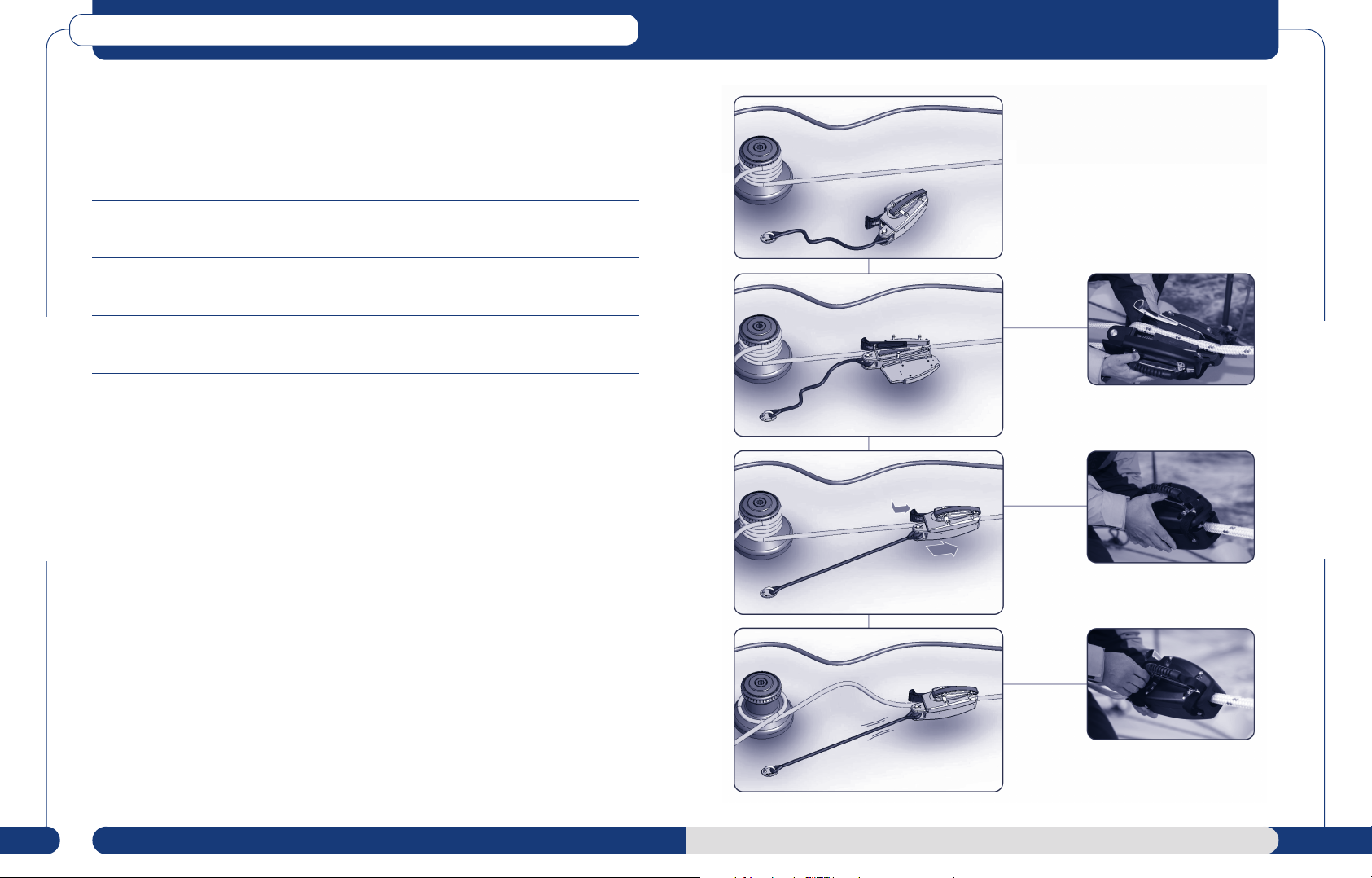
The ZS OPEN can be locked onto any loaded line to give the perfect solution for peeling spinnakers,
headsails, reefing and dealing with an emergency.
1. Secure strop to padeye or winchbase of sufficient strength and aligned as close to the line of
load as possible.
2. Open the sideplate and engage the ZS OPEN onto the line. Then close ensuring the sideplate
latch is securely closed.
3. Slide jammer along the line so the strop is tight (this reduces runout) and engage jaws, by
releasing the jaw latch.
4. Carefully release the original loaded line from winch so the strop and ZS OPEN jammer
take the load.
Releasing the ZS Open Jammer
The ZS Open Jammer is released by holding the handle and sliding the body forward, not pulling the
handle back. Ensure there is enough slack in the strop to allow disengagement of the Jaws.
Important Notes
How to use
Ensure prior to transferring a load that the:
How to use
• Coverplate is fully engaged onto the main body
• Latches are locked into the location pins
This ensures that the burst loads are shared by both side plates. Failure to do this will cause the
body to permanently deform and the cover plate will no longer fit. If the unit should be overloaded
the white PTFE bearing will show signs of deforming at its contact with the upper and lower faces
of the body.
10 11
www.spinlock.co.uk
ZS Open
maintenance
pages 22-23
spares
pages 36-37
ZS–RLB Remote Lockback Switch
loaded
line
loaded
line
loaded
line
load taken
on winch
For use with ZS Jammers or existing halyard locks. Allows the ZS Jaws to be pre-tensioned for
release.
ZS1214, ZS1014C, ZS1014B, ZS1618, ZS1618C and ZS1618B Jammers are all supplied with jaws
and rear block drilled for trip line attachment and lead. Older style ZS Jammers in this range can
be modified to use the ZS-RLB. Contact the Special Projects Team for assistance in modifying older
products.
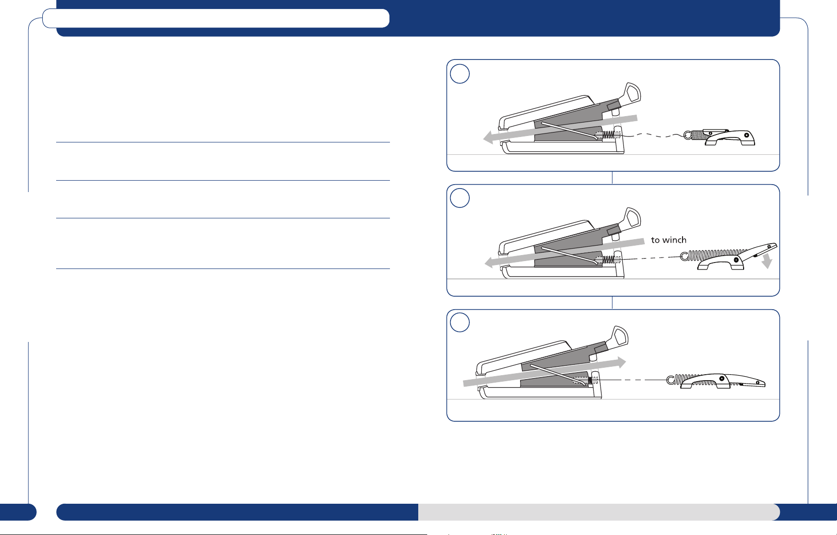
Step 1
The start position - ZS-RLB closed,trip line slack and ZS Jammer loaded.
1
Step 2
Open the ZS-RLB to pre-tension the trip line - the ZS Jammer is now ready to release.
Step 3
Take up load on winch - the ZS-RLB will automatically open the Jaws and allow the line to be
released to the winch.
2
How to use
3
How to use
12 13
www.spinlock.co.uk
ZS-RLB
installation
pages 18-19
spares
pages 36-37
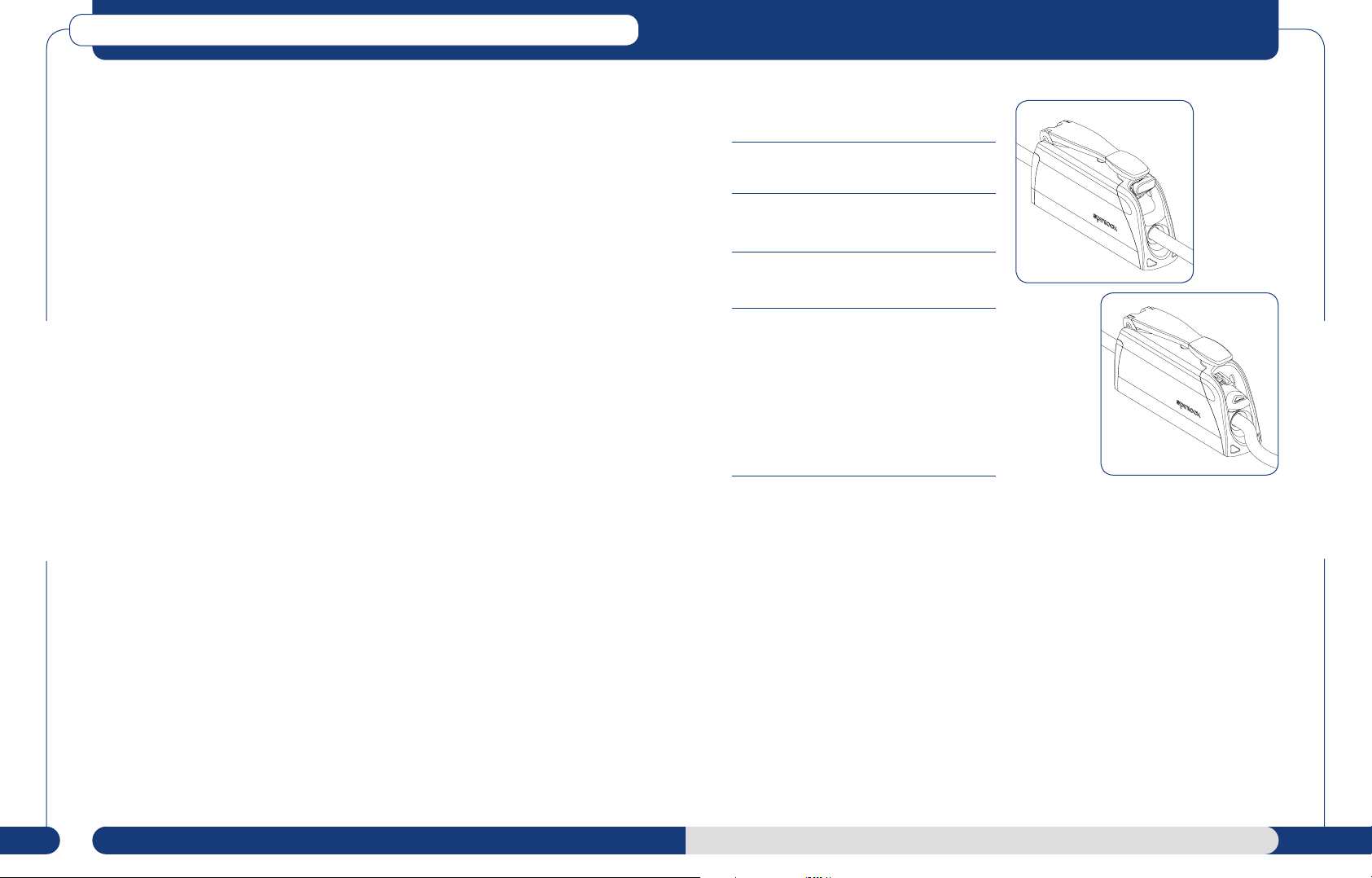
XXA0812, XXB0812 and XXC0812 Clutches
The XX powerclutch offers smooth and
controlled release on highly loaded lines.
Optimised for high performance 8-12mm
diameters, the XX fills the critical load
holding gap between clutches and high
load ZS jammers.
As well as the standard version, the XX is
offered as XXB with ceramic jaws for increased
load holding and XXC with ceramic jaws and
lightweight body. All models are offered with
‘lock open’ feature, allowing the line to freely
move in both directions with the handle closed
and all models can also be supplied ready for
remote control.
Line feeding into the XX0812 : Using a
long screwdriver, place its shaft through front
bullseye and locate tip on front face of lower
jaw. Push backwards until the jaw stops. With
the jaws in this position raise and fully open the
handle. This locks the jaws back at their biggest
clearance and allows easy threading of your
new rope.
This process is not necessary for the XX Lock
How to use
Open Version.
Release : As a safety feature, no release action
begins until the handle is rotated beyond 60
degrees.
To protect the user and rope fibre, normal
hand pressure will not release the rope above
this load.
Important : Always start the release process
with the handle in the closed position for full
release efficiency. If at any time you only part
open the handle we advise completely opening
and closing (cycling) the handle, with the line
secured on the winch, to ensure the mechanism
is re-set for full release next time. Failure to do
this will result in poor holding power and worn
jaw surfaces.
Sleeving : Secondary sleeving (internal or
external) of the rope significantly improves the
performance levels of any clutch or jammer. Any
external sleeving should be a very tight fit. If you
are going to sleeve your rope, ensure that the
overall diameter does not exceed 12mm and has
a taper to run freely through the clutch. Core
inserts provide the smoothest transition
for fast line speed applications.
XXA0812, XXB0812 and XXC0812
Lock Open Clutch Operation
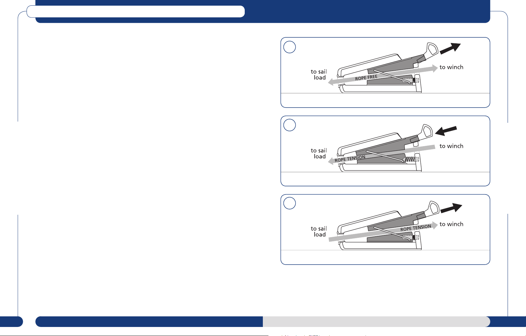
1. With the lock open latch in the UP position
the line runs freely through the XX
2. When the latch is pushed DOWN with the
handle closed, the line is held secure
3. To release the line, the handle can either be
opened normally, OR
4. With the handle in the closed position, move
the lock open latch to the UP position. When
the load is taken securely on a winch the
jaws will automatically release, allowing the
line to run free, with the handle still in the
closed position. The jaw will remain open
until the latch is returned to the down
position, even if the handle is cycled.
Watch the XX Demonstration Video at www.spinlock.co.uk
How to use
With your new rope threaded you can now
close the handle. As the handle closes, the XX
clutch will automatically engage the rope.
14 15
www.spinlock.co.uk
XX0812
installation
pages 20-21
maintenance
pages 24-27
spares
pages 36-37

ZS Alloy Jammer
ZS Carbon Jammer
If fitting to the deck, install the jammers forward of the winch, close enough for easy operation
of the handle and latch, ensuring enough space is left behind the product for removal of the jaw
assembly for maintenance. The jammers are provided with studs (A4-70 stainless steel) in a pattern.
This helps spread the load into lightweight composite decks or masts.
They are a tight fit to ensure good thread engagement. Drilling templates for deck layout are
provided with the product.
Warning : The studs should be screwed a maximum of 15mm into the body. Over tightening
may damage internal bearing surface
Side Mounting : Replace the six body fasteners with longer bolts. These can be inserted from
either side by removing the round insert nuts. These must be at least A4-70 stainless steel bolts if the
maximum safe working loads are to be reached. Refer to specification chart (page 7).
Double check the hole pattern is correct for the jammer before drilling. The pattern is not
reversible.
Mast Mounting : Mast mounting plates are available, see page 34 for details. CAD templates
can be download from:
www.spinlock.co.uk/cadlibrary
The Jammers are not designed to withstand high side loads. If the lead angle to the winch is greater
than 10 degrees, fit lead blocks or organisers aft of the jammers. Contact the Special Projects Team
for details of our TSR High Load Aft Organiser.
Installation
Spinlock offer ceramic jaw surfaces for specific rope covers and ensure more consistent long term
holding
If fitting to the deck, install the jammers forward of the winch, close enough for easy operation
of the handle and latch, ensuring enough space is left behind the product for removal of the jaw
assembly for maintenance. ZS Carbon Jammers are provided with studs (A4-70 stainless steel) in a
staggered pattern. This helps spread the load into lightweight composite decks or masts.
Warning : The studs should be screwed a maximum of 15mm into the body. Over tightening
may damage internal bearing surface.
They are a tight fit to ensure good thread engagement. Drilling templates for deck layout are
provided with this product. Double check the hole pattern is correct for the jammer before
drilling. The pattern is not reversible.
Side mounting : ZS1014B and ZS1618B Carbon Jammers are designed to be bonded.
Mast Mounting : Mast mounting plates are available, see page 34 for details. CAD templates
can be download from:
www.spinlock.co.uk/cadlibrary
Bonded Mounting : ZS1014B and ZS1618B are designed for bonding directly onto decks,
spars and booms.
Note: we are unable to provide engineering data on materials and instructions for bonding.It
is essential to refer to your own engineering design data, load data and materials supplier for
guidance.
The Jammers are not designed to withstand high side loads. If the lead angle to the winch is greater
than 10 degrees, fit lead blocks or organisers aft of the jammers. Contact the Special Projects Team
for details of our TSR High Load Aft Organiser.
Installation
ZS P-Series Jaws - Anodised jaws designed for use with Dyneema core and Polyester covered lines
ZS HC-Series Jaws - Designed for use with Dyneema core and a cover blend of Polyester with a low
stretch material such as Technora or Vectran. The ceramic surface resists polishing and wear, allows
faster engagement onto loaded line and offers improved load holding.
16 17
www.spinlock.co.uk
Warning : Post installation cleaning is essential to avoid jaw set damage, slippage and
possible rope damage on first use. Lubricant is provided. Follow maintenace instructions
on page 22.
ZS Alloy / Carbon
how to use
pages 8-9
maintenance
pages 22-23
spares
pages 36-37
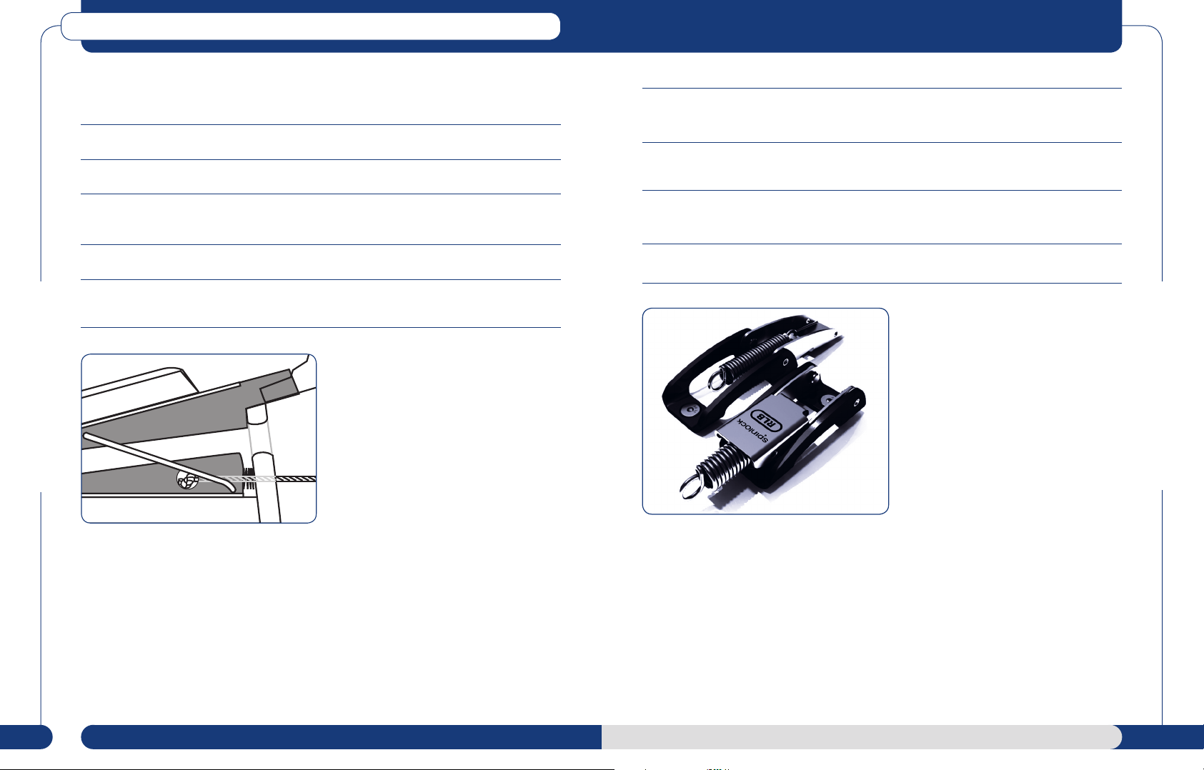
ZS–RLB Remote Lockback Switch
For use with ZS1214, ZS1618, ZS1014C, ZS1618C, ZS1014B and ZS1618B Jammers or existing
halyard locks. Allows the ZS Jaws to be pre-tensioned for release.
1. Mount the ZS-RLB in it’s preferred location using M5 fasteners.
2. Choose a suitable very low stretch control line 2-4mm which can be spliced.
5. Ensure the control line has a free, un-interrupted, low friction run to the jammer. If necessary
use bulls eyes or blocks to ensure a smooth run.
6. With the jaw set loaded on the correct diameter line and the RLB closed, adjust the control line
splice so it is just taut.
2. Attach the control line to the jaw set using a thumb knot or similar - see diagram below.
Remove rear block and jaw step ( see page 22).
3. Thread the control line through the spring and rear blockand fasten the rear block into place.
4. With the control line cut to approximately the correct length, splice the control line to the eye
of the RLB-Spring using an adjustable splice.
Installation
7. Check operation as described (see page 12 and 13). Some adjustment may be necessary
before making the splice permanent.
8. Changes in the rig set-up or line diameter will require the control line splice to be adjusted.
Installation
Open
Closed
18 19
www.spinlock.co.uk
ZS-RLB
how to use
pages 12-13
spares
pages 34-35

XXA0812, XXB0812 and XXC0812 Clutches
1. Align the clutch with the required rope lead, checking height and minimising the angle
of alignment.
2. Drill two holes to suit the M8 fasteners using template (never drill through the clutch). For
spars, etc. where no access is possible, use an M8 tap to thread the surface material, ensuring
the material has sufficient strength to carry the full clutch load. The fasteners
must be replaced with M8 A4-80 stainless socket cap or CSK machine screws for the XXB
and XX0812, or M8 titanium socket cap or CSK machine screws for the XXC0812.
3. Check each fastener (already pre-assembled into clutch) to make certain that its hexagonal head
is properly seated in its locking moulding.
4. Fasten clutch firmly after sealing upper threads with silicone sealant. In through-deck
applications any excess thread can now be ground off.
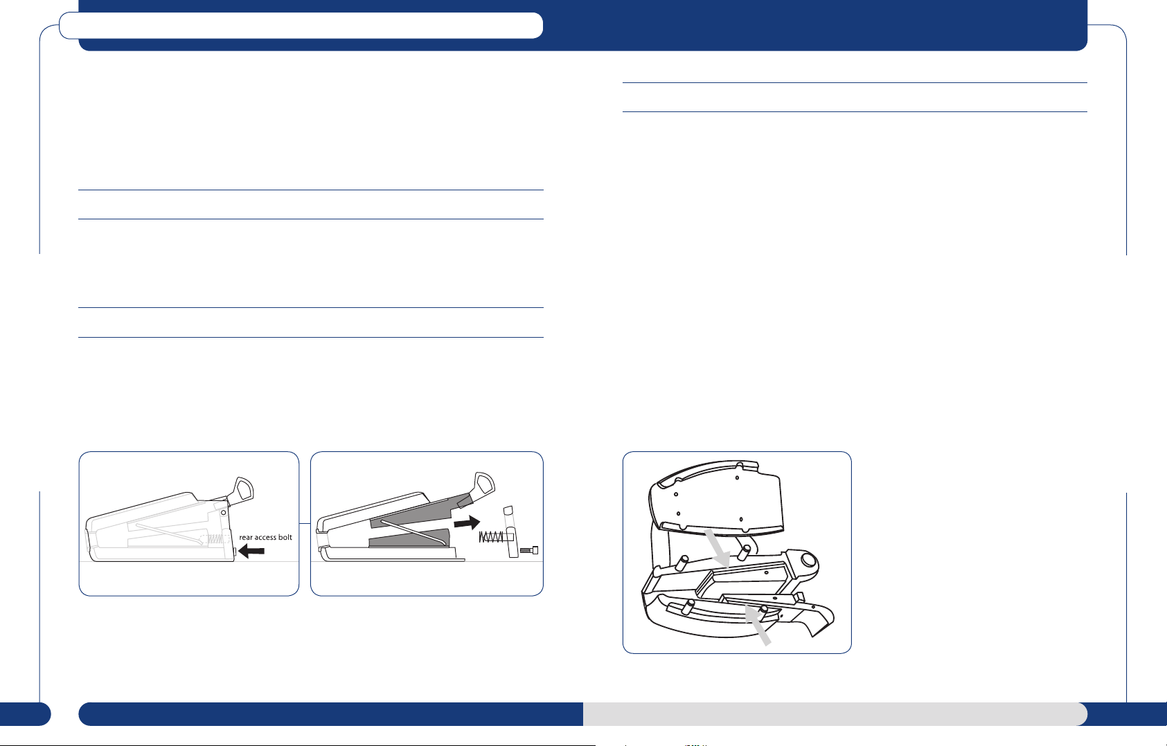
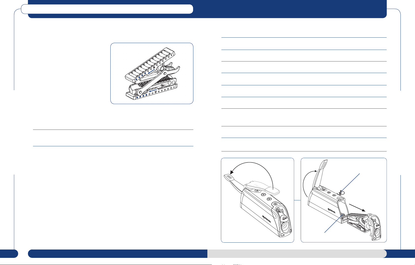
To access the fasteners or remove jawset : The XX0812 and XXB0812 is supplied fitted
with 2 x High Tensile A4-80 stainless steel hex head fasteners and the XXC0812 is supplied with 2
x M8 Titanium Hex Head Fasteners.
If you want to fit your own fasteners, you will only need to remove the rear end moulding to gain
access to the aft fixing position.
The forward fastener can be accessed from above (see Diagram 1). The simplest way to remove this
Installation
fastener is to remove the nut and washer and turn the product upside down. The M8 fastener can
now be removed.
1
M8 fastener
2
Installation
3
90º
M5 Allen screw
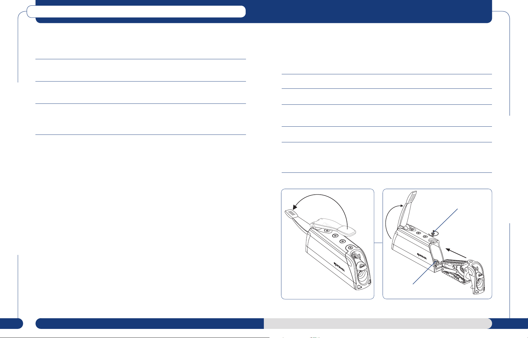
For Lock Open Versions, ensure the lock open latch is in the down position.
Lift handle and rotate fully open and then back to 90º vertical. Access to the M5 Allen screw on the
top surface that retains the rear moulding. Remove this screw. (See Diagram 2 and 3).
Hold rear cover at top, pull out from the top (See Diagram 3) pivoting around the top.
When the top of the moulding has rotated free of the body, lift the rear moulding to unhook its base
from the body and slide the jawset out. Excessive force is not necessary when performing removal
correctly and may damage irrepairably the jawset if used (See Diagram 3).
The fastener will now be visible. Leave the retaining moulding in place. (See Diagram 3).
20 21
www.spinlock.co.uk
Watch the XX Jaw Set Removal Video at www.spinlock.co.uk
XXC0812 / XX0812
how to use
pages 14-15
M8 fastener
maintenance
pages 24-27
spares
pages 36-37
ZS Alloy, ZS Carbon and ZS OPEN Jammers
Spinlock ZS Jammers are made from the highest quality materials for durability and low maintenance
in a harsh marine environment.
ZS Jammers are carefully designed for easy and regular servicing at sea. Their life and performance will
be improved if regularly flushed with fresh water.
The jaws can be easily removed for inspection and replacement:
For ZS Alloy and ZS Carbon
• Remove the screw securing the rear block.
• Remove rear block.
• Pull out the handle and jaw assembly.
For ZS OPEN
• Open the sideplate to allow removal of the jaw assembly, remove jaw engagement spring -
compress jaws together and extract sideways.
ZS Alloy, ZS Carbon and ZS Bonded
Maintenance
All
• Check for excessive wear on the grip surface - the black anodised surface, if worn, will have
silver aluminium showing through.
• Check condition of the white bearings surfaces are clean and smooth. Replace if necessary.
• Ensure all internal faces are clean and smooth.
• Ensure the load and rope type are considered when selecting new jaw set types (see page 16).
The white jaw bearings should be lubricated only with silicone grease.
Do not use mineral oil or solvent based lubricants like WD40.
Replacement jaw sets must be installed with grease provided.
For further information and instructions on maintenance of ZS jammers, please refer to the Spinlock
website or contact prosupport@spinlock.co.uk
ZS OPEN
Maintenance
22 23
www.spinlock.co.uk
ZS Alloy / Carbon
how to use
pages 8-11
installation
pages 16-17
spares
pages 36-37
XXA0812, XXB0812 and XXC0812 Clutches
General maintenance:
Three Simple Steps – flush, drain and lubricate
1. The internal mechanism should be regularly flushed out with fresh water through the end
bullseyes, and the handle pivot area.
2. Check that the lower ‘drainage’ holes in both end mouldings are clear of any debris. This will
help reduce the accumulation of any rope debris building up inside the product.
3. Lubricate handle pivot areas with a silicone grease. Unless this simple procedure is carried out
regularly, the specified performance will not be achieved. Take care not to contaminate rollers
or jaw surfaces with any lubricant.
Note : Any decrease in performance is usually caused by lack of maintenance and servicing. The
XXC0812 and XX0812 relies on the smooth running of 2 sets of roller bearings for maximum
performance. The rollers and their ‘running’ surfaces must remain as clean as possible.
Removal from deck
If removing the XX0812 from the deck, care must be taken to ensure the fasteners do not damage
the internal mechanism and plastic rear moulding. Do not hammer fasteners from below.
Watch the XX Servicing Video at www.spinlock.co.uk
Full servicing and Jaw Replacement:
The clutch should be given a thorough service periodically to ensure maximum performance is
maintained. The clutch mechanism is fully accessible whilst attached to the deck - even with other
clutches banked alongside - by the following steps.
1. Remove the rope from the clutch.
2. For Lock Open Versions, ensure the lock open latch is in the down position.
3. Lift handle and rotate fully open and then back to 90º vertical. Access to the M5 Allen screw
on the top surface that retains the rear moulding. Remove this screw.
4. Hold rear cover at top, pull out from the top (See Diagram 3) pivoting around the top.
5. When the top of the moulding has rotated free of the body, lift the rear moulding to unhook
its base from the body and slide the jawset out. Excessive force is not necessary when
performing removal correctly and may damage irrepairably the jawset if used.
90º
M5 Allen screw
Full Servicing
General Maintenance
M8 fastener
24 25
www.spinlock.co.uk
XX0812
how to use
pages 14-15
installation
pages 20-21
spares
pages 36-37
XXA0812, XXB0812 and XXC0812 Clutches
XX & XXC
ROLLERCAGE
FITMENT
FRONT BACK
6. After removal, thoroughly clean all components and body with fresh water and inspect the
following critical items :
Roller Cages (both are identical) -
unclip from jaw and look for signs
of wear or flats on the roller surfaces.
If flats are found replace & consider
upgrade to XX-ROLL+. Ensure rollers
cages are re-attached in correct
orientation.
Jaw Bearing Surfaces - ensure that
both are clean and smooth.
Jaw Grip Surfaces - clean off any rope debris. Check for excessive wear on the grip
surface. If the black anodised surface has aluminium showing through, replace with a new
XX-KIT, XXB-KIT or XXC-KIT assembly as appropriate.
Warning : do not use XXC-JAW in XX clutches as serious damage, harm and injury
could occure.
Jaw Linkplates - check these are attached to both sides of both jaws with pins and secured
by both pins. Ensure free movement of link plates/pins in jaws.
Release Pin - located centrally in top jaw. Check for any signs of surface wear.
Full Servicing
Re-assembly
1. For Lock Open Versions ensure the lock open latch is in the down position.
2. Lift handle and rotate fully open and then back to 90º vertical.
3. Insert jaw assembly in body of XX. No force should be applied in stages 3-5.
4. Angle rear moulding backward, to locate lower fixing hooks in body.
5. Rotate top of cover into place flush with XX body.
6. Insert M5 Allen screw into the top surface that retains the rear moulding. Hand tighten only.
7. If Lock Open version, ensure latch is fully operational in both up and down positions as well as
opening and closing the handle fully.
8. For standard versions, open and close the handle fully to ensure fully operational.
9. Open handle fully and thread rope through XX body. See page 15 for rope feeding advice.
90º
M5 Allen screw
Full Servicing
Clutch Body - flush clean inside, paying particular attention to the upper and lower roller
surfaces, the two drainage runs in the base and their exits at the end mouldings.
Handle - do not remove this from the body. Check that the operation holds the handle in
the closed and fully open position (via the leaf spring mounted at the front of the wedge).
26 27
Lubricate pivots with silicone grease.
www.spinlock.co.uk
XX0812
how to use
pages 14-15
M8 fastener
installation
pages 20-21
spares
pages 36-37
 Loading...