

Page 1

Not to be distributed without prior consent of SPI Lasers UK Ltd.
Slide: 1
FS-S00149-Rev A
redPOWER PRISM OEM
Prism Module Fiber Laser
Quick Start Guide
29/06/2016
Page 2

Not to be distributed without prior consent of SPI Lasers UK Ltd.
Slide: 2
FS-S00149-Rev A
• Customer Requirements Pre Install Water Supply & Fittings.
• Customer Requirements Pre Install Electrical Connections
• Customer Requirements Pre Install RS232/485 Communication...
• Customer Requirements Pre Install 37 Way Dsub Connections
• Customer Requirements Pre Install Protective Conductor (Earth)
• Customer Requirements Pre Install Unpacking & Handling
• Customer Requirements Installing Laser Mounting Laser In ...
• Electrical Connections to Laser
• Start Up/Shutdown Procedure for Prism Laser.
• SPI Service Contacts
Contents
29/06/2016
Page 3
Not to be distributed without prior consent of SPI Lasers UK Ltd.
Slide: 3
FS-S00149-Rev A
Before the redPOWER PRISM OEM laser is delivered to the customer, the customer must ensure that the following
Utilities are available.
• Water Supply : Cooling Water Requirements
• Integrators must ensure that the water condition meets the requirements set out in the following tables and in
the manual below.
• SM-S00481 redPOWER Prism OEM Fibre Laser Instructions for Use
• Ensure that the hose connections are leak free and tested before electrical operation of the laser .
• SPI recommend that an appropriate filter is installed in line to the flow lines of the laser. The grade of filter is
100µm
• Pre-treated water and additives for prevention of corrosion, scaling and microbial growth are available
commercially, for example from NALCO and Optishield.
• additives may reduce the heat capacity of the water. The flow rate must be increased to compensate.
• The following table will show the specification for the chiller to ensure correct cooling of the OEM and PIPA-Q
BDO head.
Customer Requirements Pre Install
Water Supply & Fittings
29/06/2016
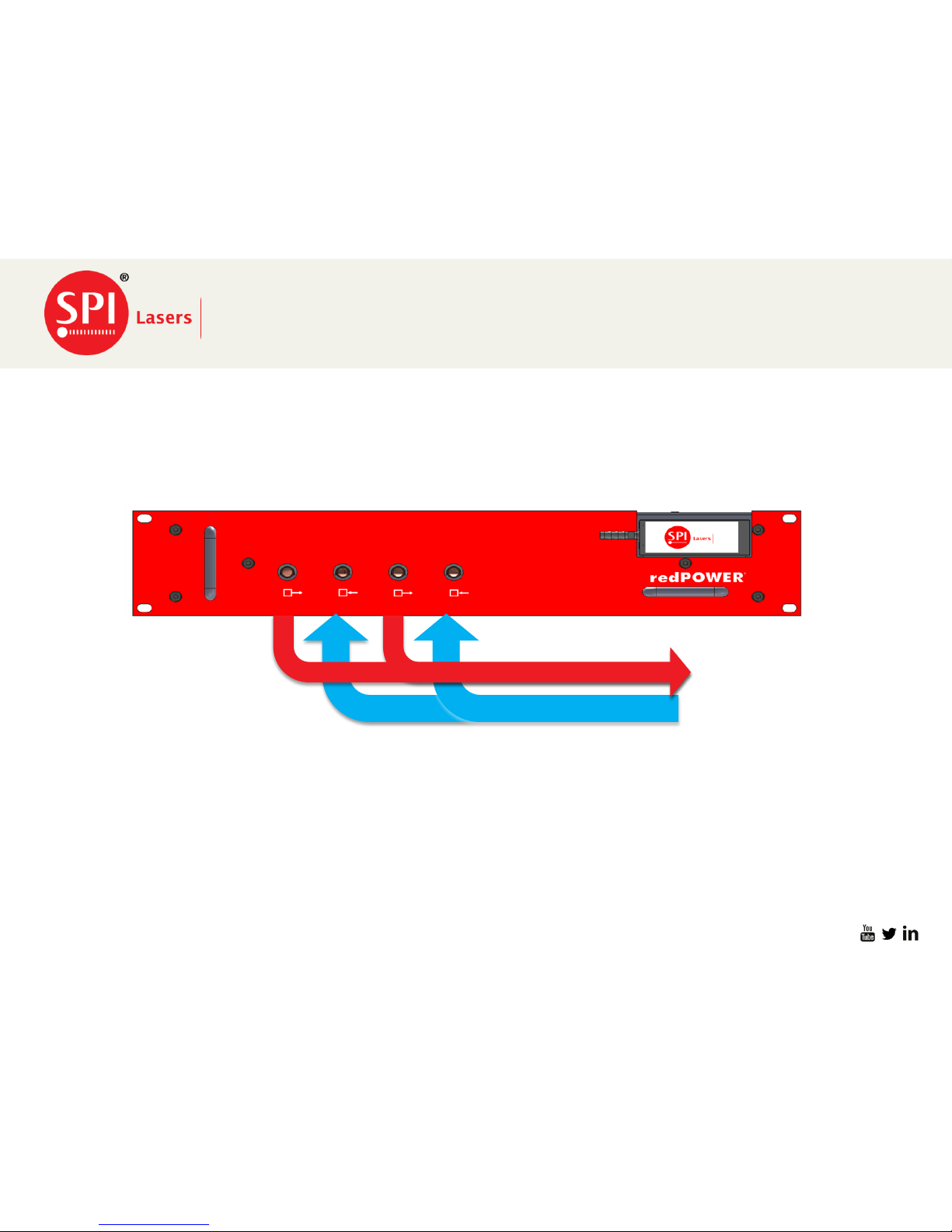
Flow from Chiller
or House Water
Return to Chiller or
House Water
Page 4

Not to be distributed without prior consent of SPI Lasers UK Ltd.
Slide: 4
FS-S00149-Rev A
Customer Requirements Pre Install
29/06/2016
Parameter
Min
Max
Units
Appearance
Clear and without sediment
-
Particle size
-
100
μm
Hardness (mg CaCO3 per litre)
-
300
mg/l
Electrical conductivity at 25°C
22
2200
μScm
-1
pH
6.5
9.0
-
Cooling Water Requirements
Parameter
Min
Max
Units
Notes
Cooling Water
Temperature
18
30
ºC
It is important that condensation will not occur. Refer to
Section 15.1. of SM-S00481 redPOWER Prism OEM Fibre
Laser Instructions for Use
Input Pressure
-
6
bar
Flow Rate
10
l/min/kW
At 20°C water temperature.
Pressure Drop
Long Module
-
2.5
bar
Pressure Drop
Short Module
-
2.0
bar
Cooling Requirements (Base plate)
Rated Power
300W
500W
750W
1000W
1500W
Units
Chiller Capacity
900
1500
2250
3000
4500
W
Required Chiller Capacity
Page 5

Not to be distributed without prior consent of SPI Lasers UK Ltd.
Slide: 5
FS-S00149-Rev A
Parameter
Min
Max
Units
Notes
Cooling Water
Temperature
15
35
ºC
It is important that condensation will not occur. Refer to Section
15.1. of SM-S00481 redPOWER Prism OEM Fibre Laser
Instructions for Use
Input Pressure
-
6
bar
Flow Rate
0.5
2
l/min/kW
At 20°C water temperature.
Pressure Drop
1.6
5
bar
Chiller Capacity
0.5
-
kW
29/06/2016
Customer Requirements Pre Install
Drinkable tap water is likely to meet the above requirements, and water meeting the requirements of VDI3803,
Appendix B, Table B3 does.
When designing the water cooling system, the Laser Integrator should consider the following:
• Deionised water is not permitted in the cooling circuit as the generally high levels of dissolved O2 and CO2 in
deionised water cause corrosion.
• Due to the cooling circuit of the laser and BDO incorporate copper, nickel plating and stainless steel, aluminium and
plain carbon or low alloy steels should not be used as galvanic corrosion may occur.
• Bacterial growth, scaling and corrosion will cause low flow rates and reduce heat transfer from the laser therefore
pre-treated water and additives for prevention of corrosion, scaling and microbial growth are available commercially,
for example NALCO and Optishield.
NOTE: Additives may reduce the heat capacity of the water. Therefore the flow rate must be increased to compensate.
Cooling Requirements (PIPA-Q Optical Connector)
Page 6

Not to be distributed without prior consent of SPI Lasers UK Ltd.
Slide: 6
FS-S00149-Rev A
Customer Requirements Pre Install
29/06/2016
• Water Connections PIPA-Q Optical connector.
• The water connections to the PIPA-Q optical connector requires a separate water supply which can be achieved
by using a two channel chiller unit with independent settings for each channel.
• It is essential that the PIPA-Q optical connector is adequately cooled with a source of clean, chilled water in
accordance with the specifications in the table above . Operating the PIPA-Q optical connector without an
adequate flow of cooling water may result in catastrophic damage.
• It is the customers responsibility to provide the fittings and hose for the install of the laser, SPI recommends the
use of John Guest fittings as shown below.
• John Guest 10mm Equal Elbow PM0310E
10mm Equal Straight PM0410E
10mm Locking Clip PM1810R
10mm Plug PM0810R
10mm LLDPE Tubing (Cold Plate) PE-1007-100M-*
6mm LLDPE Tubing (PIPA-Q) PE-0604-0100M-*
10mm Equal Elbow PEM0310W
Tube Cutter TSNIP
• Essentra End Cap FCWA-0095-013
Page 7
Not to be distributed without prior consent of SPI Lasers UK Ltd.
Slide: 7
FS-S00149-Rev A
Customer Requirements Pre Install
Electrical Connections
29/06/2016
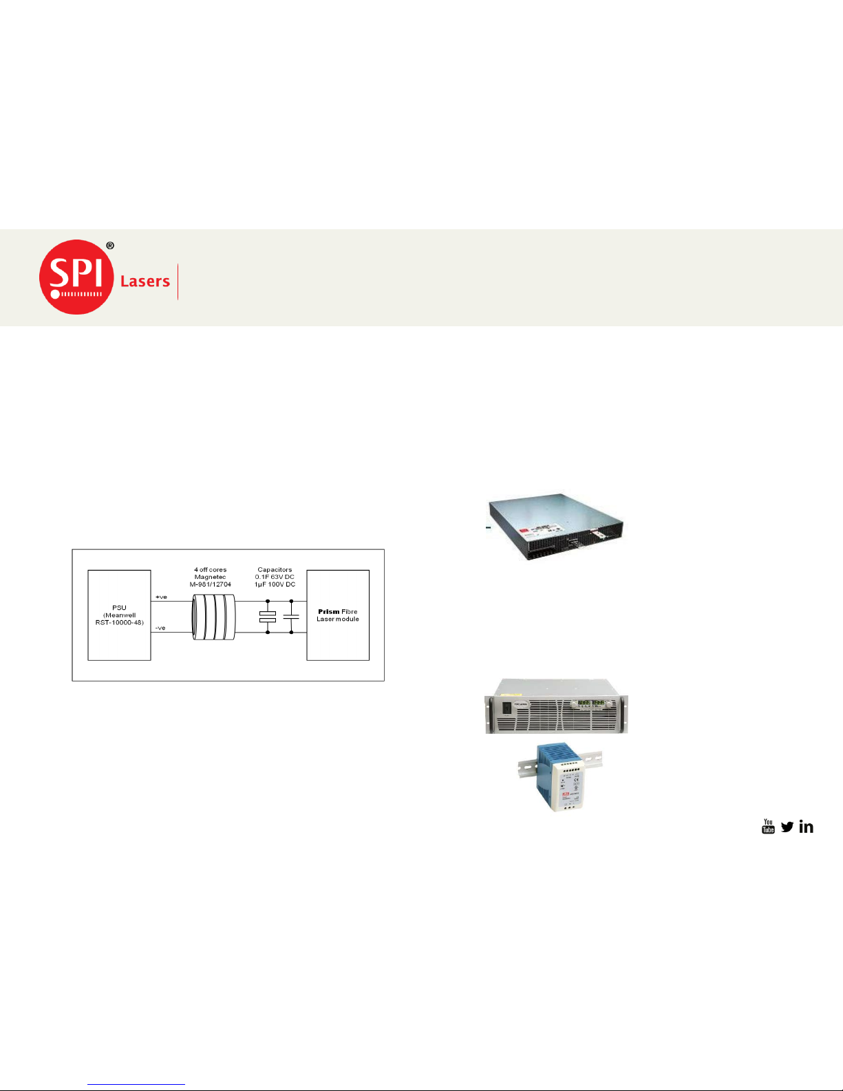
Mains DC Power Supply
Electrical power for the pump diodes must be provided by an external DC power supply.
Power for the internal electronics must be provided by a DC auxiliary power supply.
SPI Lasers recommends the following DC power supplies for the pump diode supply
• Customer sourced Power Supply
• Customer must follow Supplier instruction Manual for Parallel Operation if more than one power supply to be used.
• Must conform to the specifications in the following slide for EOL (End Of Life) Current and Voltage.
• TDK Lambda GEN 50-200-3P400
• Aux 24V PSU(0.5A Rated) 24 ±5% Isolating
• MEAN WELL RST-10000-48
• May require additional Capacitive Support for first few
milliseconds of operation. See Figure below.
Page 8

Not to be distributed without prior consent of SPI Lasers UK Ltd.
Slide: 8
FS-S00149-Rev A
Customer Requirements Pre Install
29/06/2016
Parameter
Min
Typ
Max
Unit
Note
Voltage
Adjustment
Range
48 - 51
V
DC
1500W Prism Fibre Laser
Output Current
-
120
135
A
1500W Prism Fibre Laser
Output Load
Regulation
-
-
0.5
%
10% to 90% load variation
Output Line
Regulation
-
-
0.5
%
±10% input variation
Output Ripple
and Noise
-
-
0.5
%
20MHz measurement bandwidth
At full load, nominal input voltage
Power supply to be able to energise
≥4,000µF of load capacitance under
direct on-line load power application
(cold start)
Hold Up Time
5
-
-
ms
At full load, nominal input voltage
Transient
Response
-
-
0.5
%
The input current can change from 0A to
135A in less than 5µs. If the PSU cannot
respond fast enough additional
capacitive support will be required to
ensure that the output power is
maintained over the first few
milliseconds.
Stability
-
-
0.5
%
Over time and temperature
• To ensure compliance with EN
60204-1 Safety requirements for
electrical equipment for
measurement, control and laboratory
use – Part 1: General Requirements,
an external switch or circuit breaker
and external overcurrent protection
device should be fitted.
• Use of an inappropriate pump diode
power supply will invalidate the
warranty on the Prism Fibre Laser.
Further information can be provided
by request from SPI Lasers.
• A power supply capable of providing
0.5A at 24V DC which is
appropriately approved and protected
is required to power the control and
monitoring circuits in the Prism Fibre
Laser.
Page 9
Not to be distributed without prior consent of SPI Lasers UK Ltd.
Slide: 9
FS-S00149-Rev A
Customer Requirements Pre Install
29/06/2016
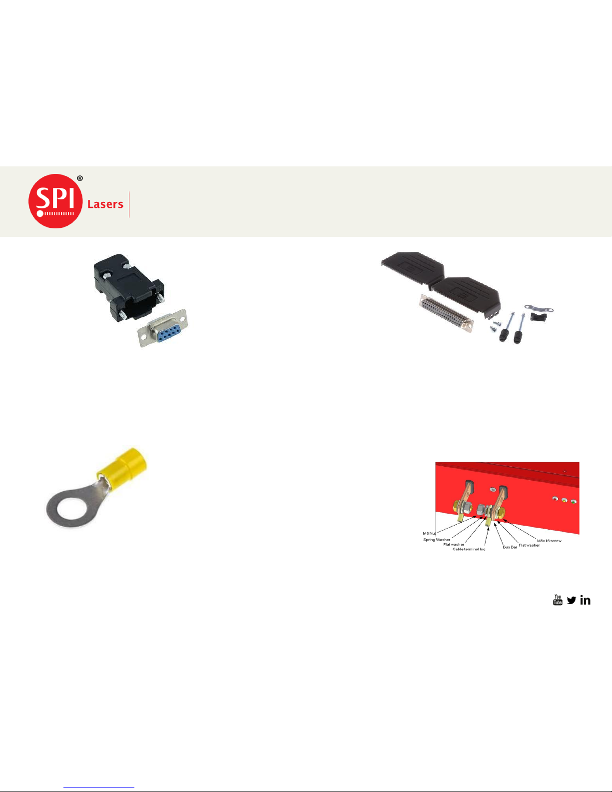
37 way Dsub Female connector
The connector is required for the input
and output signals from the Prism OEM
module
9 Way Dsub x 2 for RS232/485 Cable
The RS232 cable is required for the Customer to
communicate with the Prism OEM using the
PrismView Graphical User Interface program
provided with the laser.
M8 Ring Crimp
The ring crimp is used for the DC power supply cables that
the customer must provide between the Buss bars of the
PSU and the OEM module. Cable size recommended for
the DC power supply to OEM is 10mm2
Page 10
Not to be distributed without prior consent of SPI Lasers UK Ltd.
Slide: 10
FS-S00149-Rev A
Customer Requirements Pre Install
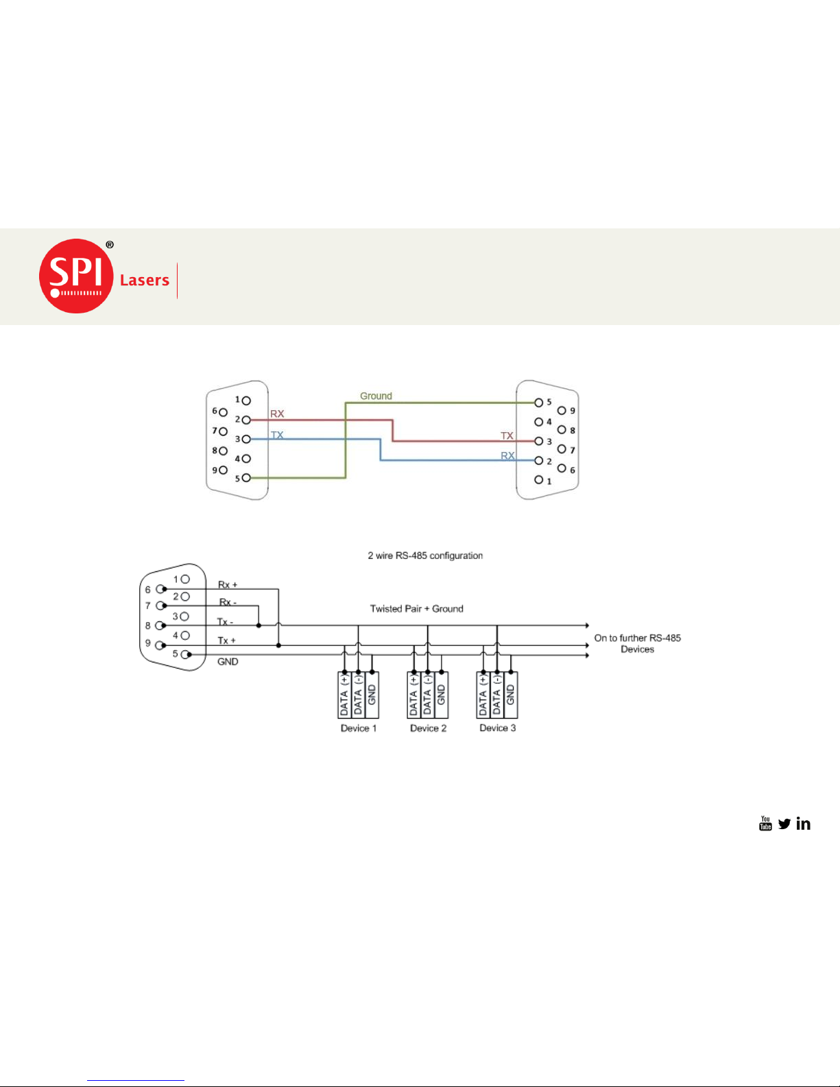
RS232/485 Communication Cable
29/06/2016
RS232 Communication Cable
RS485 Communication Cable
Page 11
Not to be distributed without prior consent of SPI Lasers UK Ltd.
Slide: 11
FS-S00149-Rev A
Customer Requirements Pre Install
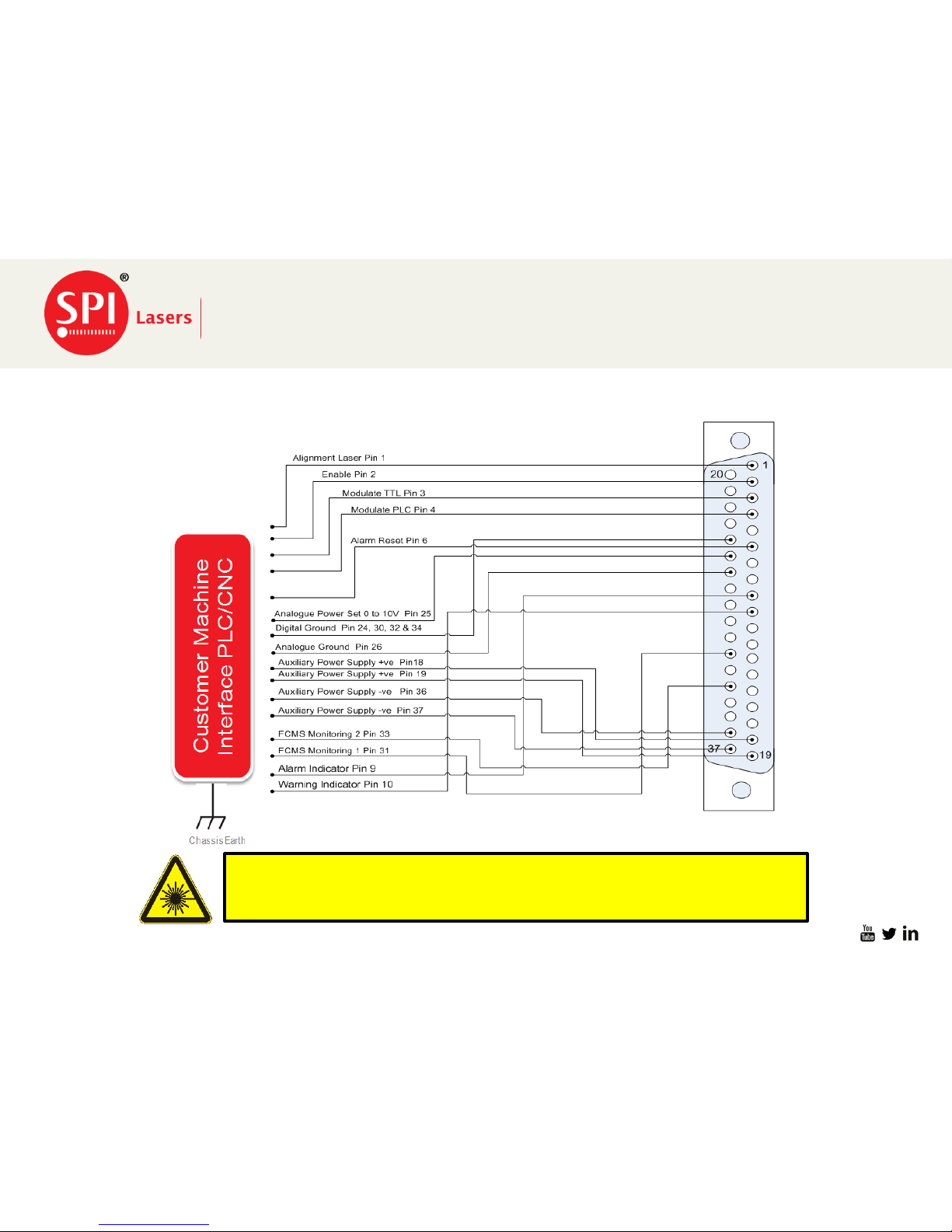
37 Way Dsub Connections
29/06/2016
NOTE: The integrator safety circuit must include the FCMS such if there is no
continuity between the FCMS pins on the user interface connector the Prism
Fibre Laser is disabled and the industrial laser machine is put in a safe state.
To help the customer the following cable diagram shows the minimum connection that can be achieved which
will operate the laser and allow alarm reset. For the full list of pin outs please refer to the product manual
SM-S00481 Prism OEM Fibre Laser User Manual.
Page 12
Not to be distributed without prior consent of SPI Lasers UK Ltd.
Slide: 12
FS-S00149-Rev A
Customer Requirements Pre Install
Protective Conductor (Earth)Terminals
29/06/2016
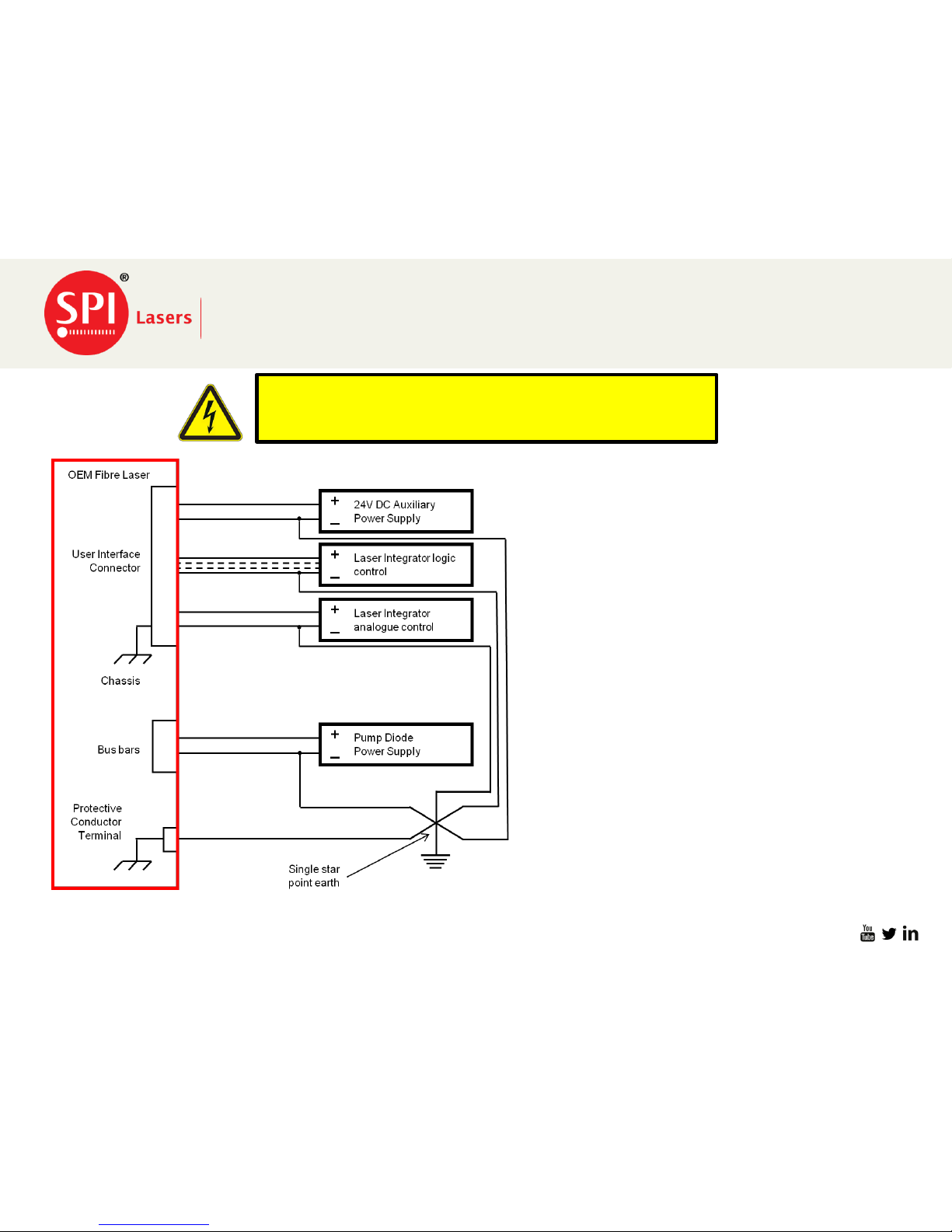
37 Way Dsub connector provides the input
for the following supplies.
• External 24VDC Aux PSU
• Input /output Logic controls from external
PLC/CNC controller.
• Analogue Control Inputs
All of the above must be connected on the
negative side of the circuit to chassis Ground
single star point.
37 way Dsub Connector
The Bus Bars for the DC input power supply
must be connected from Negative to
Machine chassis Ground Single star point
The Final and most important connection is
the Prism OEM chassis to the Machine
chassis Ground. Leaving this open may
cause the other signals to float due to
insufficient return path to the chassis ground
and closing the ground loop.
For safe operation of the Prism OEM Laser and to comply with
regional electrical codes, grounding of the machine and
equipment is of the highest importance!
Page 13

Not to be distributed without prior consent of SPI Lasers UK Ltd.
Slide: 13
FS-S00149-Rev A
Customer Requirements Pre Install
Unpacking & Handling
29/06/2016
CAUTION: The Prism Fibre Laser is heavy, precautions must be taken when
lifting and moving. Failure to do so may cause serious injury !
On arrival the following actions must be undertaken before removal of the laser from the container.
• Inspect the shipping container for any damage.
• Record all damage for insurance purposes.
The Prism Fiber Laser weighs 33kg without the BDO therefore to avoid risk of personal injury or damage to the
Prism Laser module, SPI advise that the laser must be lifted with two people or by use of a lifting crane. If the laser
is required to move over distance a trolley or similar mechanical assistance is required.
Page 14

Not to be distributed without prior consent of SPI Lasers UK Ltd.
Slide: 14
FS-S00149-Rev A
Once the Prism Laser is removed from the container the following is required.
• Inspect the Prism Laser for any signs of damage.
• Inspect the Optical Connector and the full length of the conduit for any damage
• Confirm all items have been delivered as per the shipping list including items ordered separately.
If any damage is found please take photographic evidence for insurance purposes
Customer Requirements Pre Install
29/06/2016
Page 15

Not to be distributed without prior consent of SPI Lasers UK Ltd.
Slide: 15
FS-S00149-Rev A
Once all inspections have taken place the laser can be mounted in to the machine.
3 ways of Mounting the laser.
• Slide and 19” Rack
• Ensure that the slide rails can take the weight of the Prism unit.
• Bolt the front panel to the cabinet mountings.
• Shelf and 19” Rack
• Ensure the shelf thickness can take the weight of the prism unit.
• Bolt the front panel to the cabinet mountings
• Side Fixing and Rails
• The side of the laser can be mounted to a slide unit
• Customer is required to use all 12 mounting holes to support the weight of the unit
Customer Requirements Installation
Mounting Laser In to the Machine
29/06/2016
Page 16
Not to be distributed without prior consent of SPI Lasers UK Ltd.
Slide: 16
FS-S00149-Rev A
Electrical Connections to Laser
29/06/2016
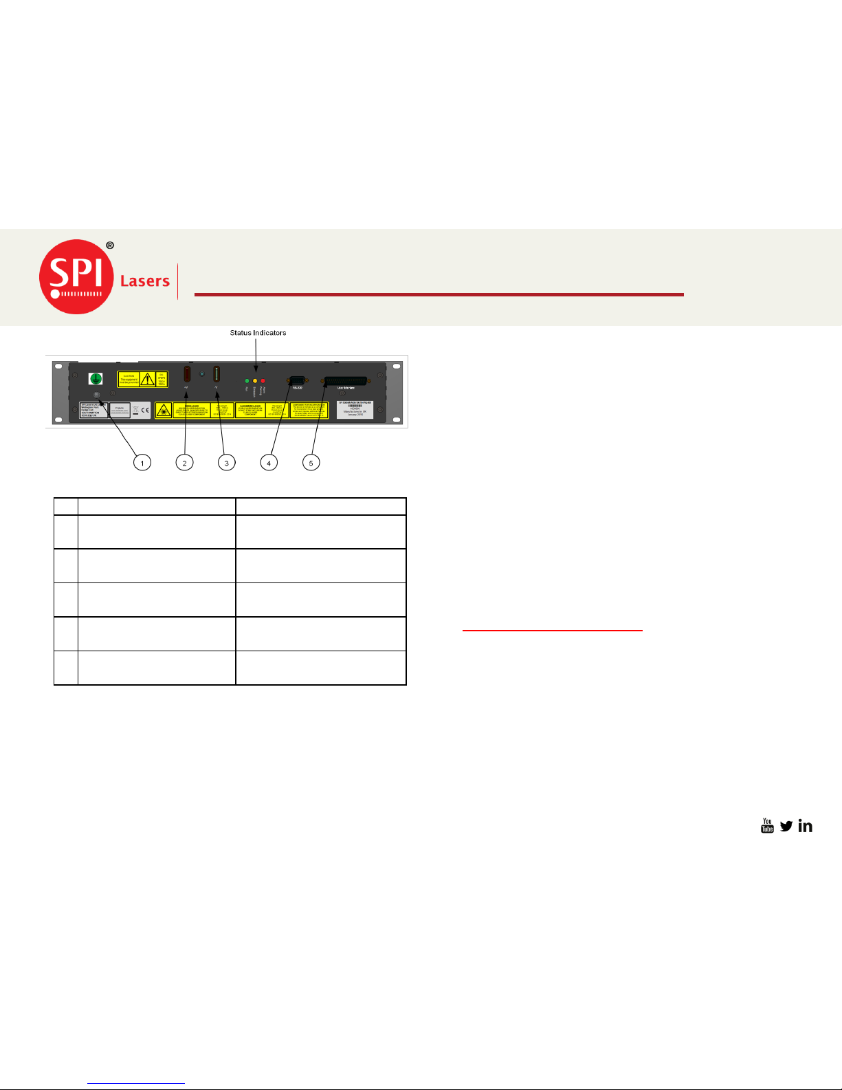
№
Function
Connector Description
1
Protective Conductor
(Earth) Terminal
M5 female thread
2
Pump Diode PSU +V
Bus Bar with two eyes for
M8 bolts
3
Pump Diode PSU -V
Bus Bar with two eyes for
M8 bolts
4
RS-232 and RS-485
9-way D-Type male
connector
5
User Interface
37-way D-type male
connector
• Connect the protective earth from Item 1 to machine
chassis ground.
• Connect the power supply Negative cable Item 3.
Ensure the negative terminal of the power supply is
also connected to chassis ground
• Connect the power supply Positive Cable Item 2.
• Connect RS232/485 Cable to item 4. Can be used to
monitor the Prism unit using the Prism GUI
Provided.
• Connect the 37 Way Dsub connector Item 5 for input
and output signals, 24V control supply to laser.
• Connect BDO to Process Head ensuring the BDO is
locked in to position.
• Once all of the above is taken care of go to
• start up/Shutdown procedure
Page 17

Not to be distributed without prior consent of SPI Lasers UK Ltd.
Slide: 17
FS-S00149-Rev A
Start Up/Shutdown Procedure for
Prism Laser.
29/06/2016
• NOTE: 24V Aux supply must be turned on before the diode power supply
• Enable line must not be high before turning on the 24V PSU. If enable is high, the laser will not enable and the line must be
cycled for the laser to work correctly.
• Setting Machine & Water controls
• Turn on Machine (Machine may control Chiller or House water)
• Turn on the Chiller or House water if external to machine (Ensure Flow to both Laser and beam delivery optics)
• Turn on 24V Auxiliary Supply to Laser Control
• Turn on Diode Power Supply
• Starting the Operation
• Set ENABLE High
• Laser Ready O/P High
• Set POWER SET High (0.5 to 10V = 5% to 100% Power)
• Set MODULATE High
• EMITTING O/P High (Laser emission status indicator now amber)
• Laser now delivering Output Power as requested.
• Shutting Down the Operation
• Set Modulate to Low
• Set Power Set to 0V
• Set Enable to Low
• Turn off Diode PSU (allow PSU to discharge)
• For a Full Shut Down State
• Turn Off 24V Auxiliary supply for control
• Laser is now in a shutdown state.
• For operation using Analogue Modulation mode consult SM-S00481 Prism Module Fiber Laser User Instructions
• Before following the process as shown, all machine interlocks, emergency stops and Beam Delivery Optics must be
in a safe position.
Page 18

Not to be distributed without prior consent of SPI Lasers UK Ltd.
Slide: 18
FS-S00149-Rev A
In the unlikely event that your laser requires service intervention, please contact your
local service office as stated below
SPI Service Contacts
29/06/2016
SPI Lasers UK Ltd
6 Wellington Park
Tollbar Way
Hedge End
Southampton
SO30 2QU
Tel: +44 (0)1489779696
Option 2
SPI Lasers LLC
4000 Burton Drive
Santa Clara
CA 95054
USA
Tel: +1 408 454 1170
SPI China Office
Room 108
Section B, Building No 3
No 7 Guiqing Road
Caohejing Hi-tech Park
Shanghai 200233
China
Tel: +86 (0) 21617 19474
SPI Lasers Korea Ltd.
A-1201 DAEBANG
TRIPLAON Business Tower
1682 Jungsan-dong
Ilsandong-gu Goyang-si
Gyeonggi-do
Republic of Korea
Tel: +82 31 926 7580
http://www.spilasers.com/our-locations/
Or Contact your Local Distributor/Integrator
Page 19

Not to be distributed without prior consent of SPI Lasers UK Ltd.
Slide: 19
FS-S00149-Rev A
29/06/2016
 Loading...