

Page 1
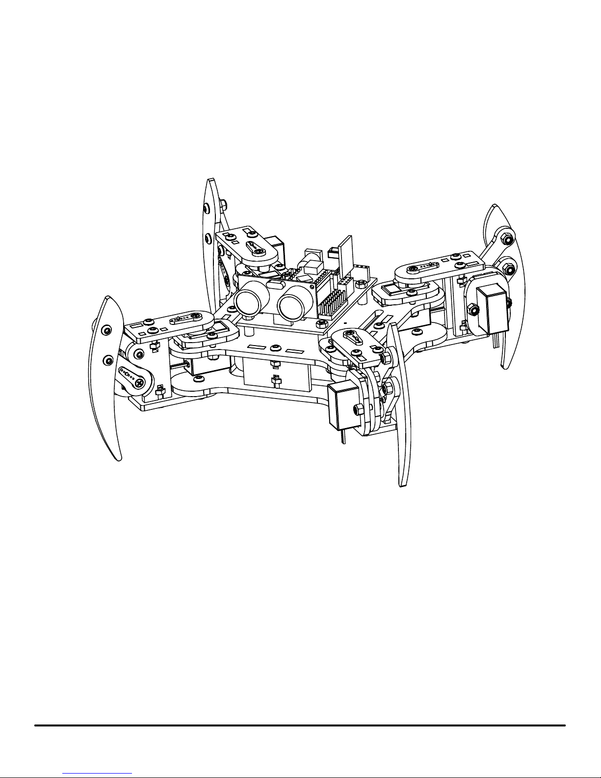
mePed v2 Assembly Manual
The mePed is an open source quadruped robot designed by Scott Pierce of Spierce Technologies, LLC.
This design is released under the Creative Commons, By Attribution, Share Alike License.
Please keep open source projects going for everyone!
Hardware source files can be found at: www.meped.io
Additional information, wiring schematics, and sample programs can be found at the official website of the mePed: www.meped.io
Copyright
mePed v2 Assembly Manual v1.0
©
2016 Spierce Technologies, LLC
1
www.meped.io
Page 2
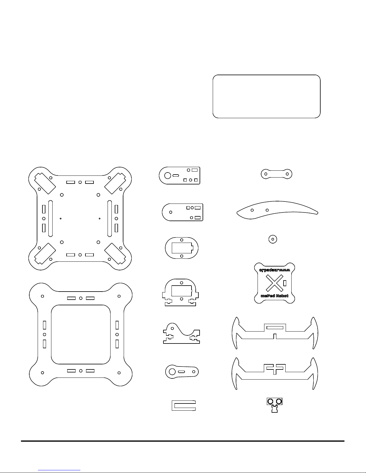
Hardware:
Here is a list of fasteners and other hardware included with your new mePed. The Servo Screws and
Servo Mount Screws referenced in this assembly manual are included with the servos and do not need
to be purchased seperately.
32ea - M3 Nyloc Nut
28ea - M3 Hex Nut
40ea - M3 x 10mm Screw
16ea - M3 x 12mm Screw
4ea - M3 x 16mm Screw
4ea - Nylon Spacer
1ea - Allen Wrench
1ea - End Wrench
WARNING:
CHOKING HAZARD - Small parts.
Not for children under 3 years.
Wood Parts:
Before laser cutting the mePed, the wood was covered with a protective masking tape to prevent the wood from becoming
smoke damaged. You will need to peel the masking tape off each part before assembling the mePed. If there is a little bit of
smoke damage anywhere on the wood after peeling off the masking tape, a light sanding will quickly remove it.
1ea - Body Top Plate
4ea - Leg Top Pivot Plate
4ea - Leg Bottom Pivot Plate
8ea - Servo Retainer
4ea - Leg Servo Mount
4ea - Leg Parallel Plate
4ea - Leg Parallel Joint
4ea - Leg
2ea - Battery Tray Spacer
Mini mePed Body
Mini mePed Leg 1
1ea - Body Bottom Plate
mePed v2 Assembly Manual v1.0
4ea - Leg Servo Arm
Mini mePed
Retaining Clip
2
Mini mePed Leg 2
Mini mePed Head
www.meped.io
Page 3
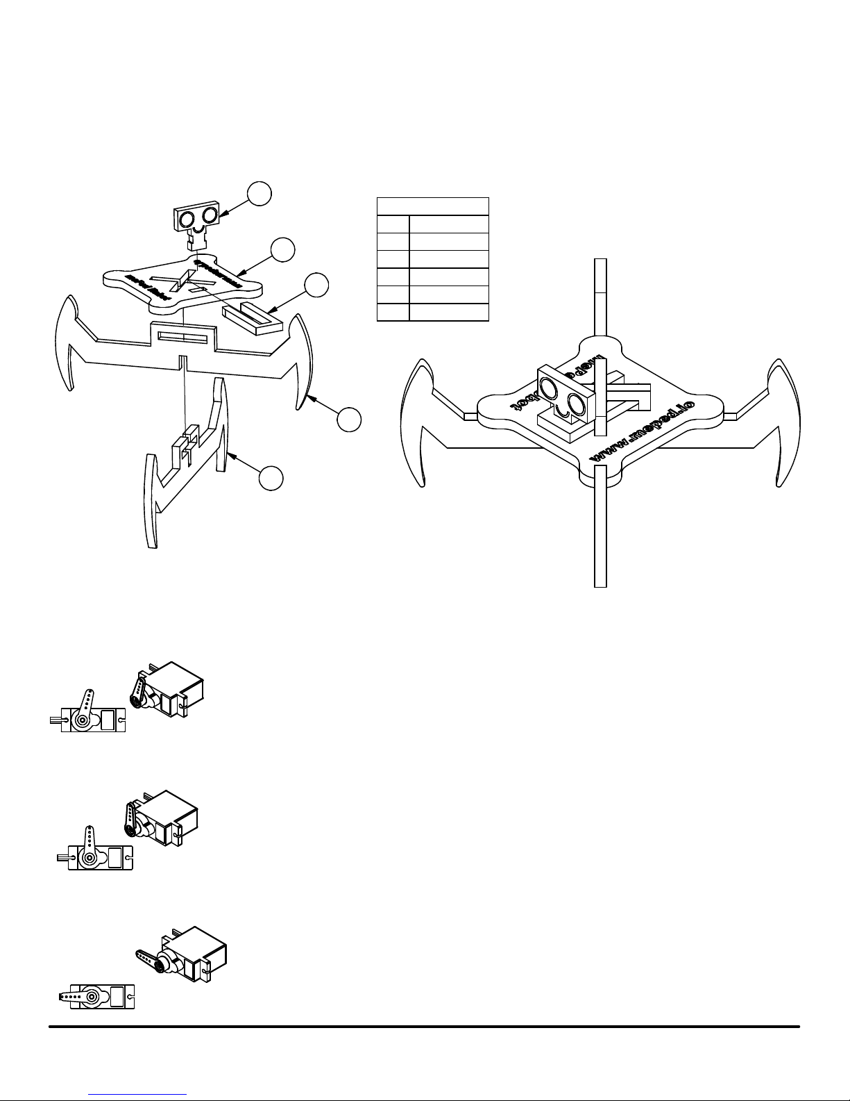
Mini mePed
Along with the full size mePed kit, we have included a Mini mePed figurine to keep you company and help you build the full sized robot!
1. Insert Leg 1 into Body
2. Insert Leg 2 into Body
3. Insert Head into Body
4. Insert Retaining Clip through the notches in the Head
4
1
5
2
3
PARTS LIST
PART NUMBERITEM
1
Body
Leg 1
2
Leg 23
Head4
5
Retainer Clip
Setting Servo Center Position
Before starting to assemble your new mePed Walking Robot, it is important to center all 8 servos that came with the kit.
The following steps will help ensure all of the servos are rotated to their center or 90° position.
Attach a Servo Arm to the servo and then gently rotate the Servo Arm clockwise until the arm stops.
It is okay if the Servo Arm does not stop at the same angle shown in the illustration above. What is
important is that we find the end stop of the Servo.
Remove the Servo Arm from the Servo and reposition it to be perpendicular to the Servo body as
shown in this illustration.
Gently rotate the Servo Arm counter-clockwise until the Servo Arm is parallel with the Servo body as shown.
After the Servo Arm is parallel with the Servo Body, remove the Servo Arm and set it aside for later assembly.
This is the Servo's center position and it is important that all 8 Servos included in the kit are
centered before starting the mePed assembly.
mePed v2 Assembly Manual v1.0
3
www.meped.io
Page 4
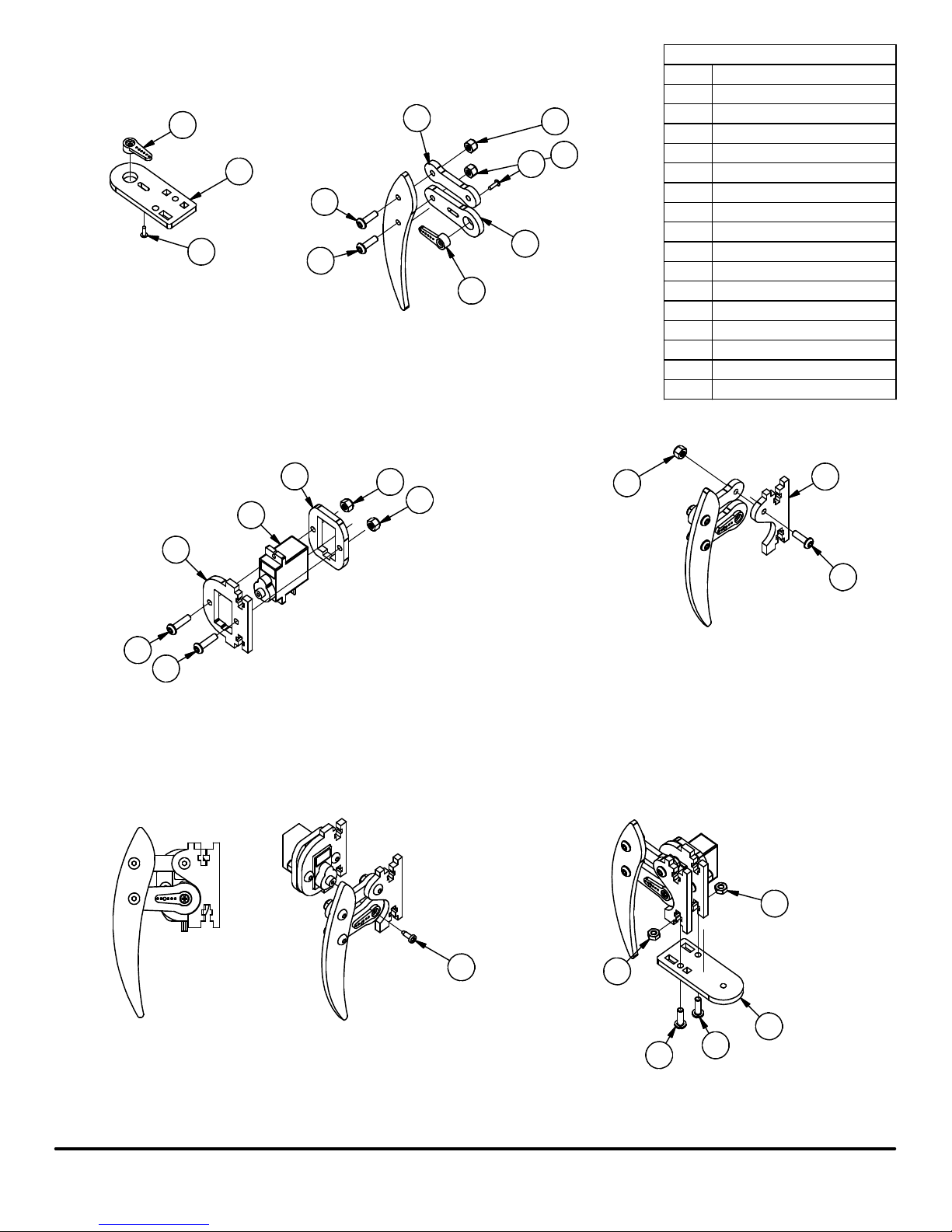
Leg Assembly
Repeat Steps 1-9 four times.
5
1
11
16
Step 1: Insert a Servo Single Arm into a Leg Top Pivot Plate and thread a Servo Mount Screw into the
Servo Single Arm from the back side of the Leg Top Pivot Plate.
Step 2: Insert a Servo Single Arm into a Leg Servo Arm and thread a Servo Mount Screw into the Servo
Single Arm from the back side of the Leg Servo Arm.
Step 3: Attach one Leg Parallel Linkage to a Leg piece using an M3 x 10mm Screw and an M3 Nyloc Nut.
Step 4: Attach the Leg piece to a Leg Servo Arm using an M3 x 10mm Screw and an M3 Nyloc Nut.
IMPORTANT! Do not over tighten the screws in Steps 2 and 3. The Leg joints should move
freely to prevent excess friction which could cause the servos to fail.
11
8
5
13
13
16
7
PARTS LIST
1
Leg Top Pivot Plate
2
Leg Bottom Pivot Plate
Leg Servo Mount3
4
Servo Screw
Servo Single Arm5
Servo6
Leg Servo Arm7
Leg Parallel Linkage8
10
Leg Parallel Plate
11
M3 x 10mm Screw
12
M3 Plain Nut
M3 Nyloc Nut13
14
M3 x 12mm Screw
Servo Retainer15
Servo Mount Screw16
Leg, Rev A17
PART NUMBERITEM
15
6
3
14
14
Step 5: Insert a Servo into a Servo Retainer.
Step 6: Insert the top end of the Servo into the Leg Servo Mount.
Step 7: Attach the Servo Retainer to the Leg Servo Mount using two
M3 x 12mm Screws and two M3 Nyloc Nuts.
13
13
13
Step 8: Attach a Leg Parallel Plate to the other end of the Leg
Parallel Linkage using an M3 x 10mm Screw and an M3
Nyloc Nut.
IMPORTANT! Do not over tighten this screw. The leg
joints should move freely to prevent excess friction which
could cause the servos to fail.
12
10
11
Step 9: With the Servo rotated to center position and the leg positioned
so the Parallel Linkage is horizontal, attach the Leg Servo Arm
to the Servo using the Servo Arm Screw supplied with the Servo.
mePed v2 Assembly Manual v1.0
4
Step 10: Attach the Leg Assembly from the previous steps to a
Leg Bottom Pivot Plate using two M3 x 10mm Screws
and two M3 Plain Nuts.
4
12
11
2
11
www.meped.io
Page 5
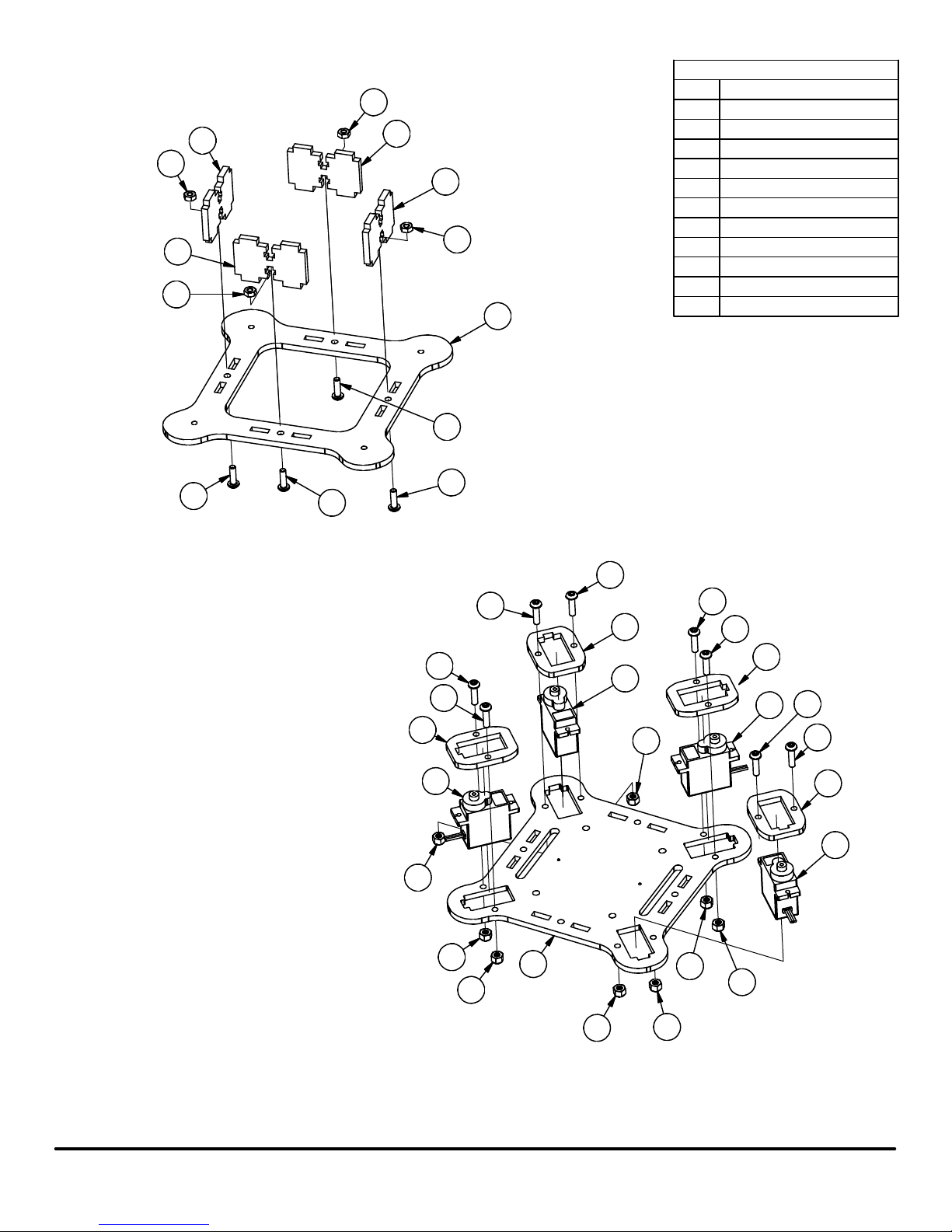
Body Assembly
8
3
8
3
PARTS LIST
3
8
8
3
2
2
1
3
4
7
PART NUMBERITEM
Body Top Plate
Servo Screw1
9 Gram Servo3
M3 x 10mm Screw2
M3 Plain Nut
M3 Nyloc Nut
M3 x 12mm Screw
Body Spacer8
Leg Servo Mount9
Servo Retainer10
Leg, Rev A20
2
Step 11: Attach four Body Spacers to the Body Bottom Plate using four M3 x 10mm
Screws and four M3 Plain Nuts.
2
2
7
7
7
10
3
4
7
7
10
3
4
7
10
7
3
7
10
3
mePed v2 Assembly Manual v1.0
4
4
Step 12: Insert four Servos into the top side of the Body Top Plate.
Step 13: Slide a Servo Retainer onto the top of each Servo.
Step 14: Attach each Servo Retainer to the Body Top Plate using
M3 x 12mm Screws and M3 Nyloc Nuts.
5
1
4
4
4
4
www.meped.io
Page 6
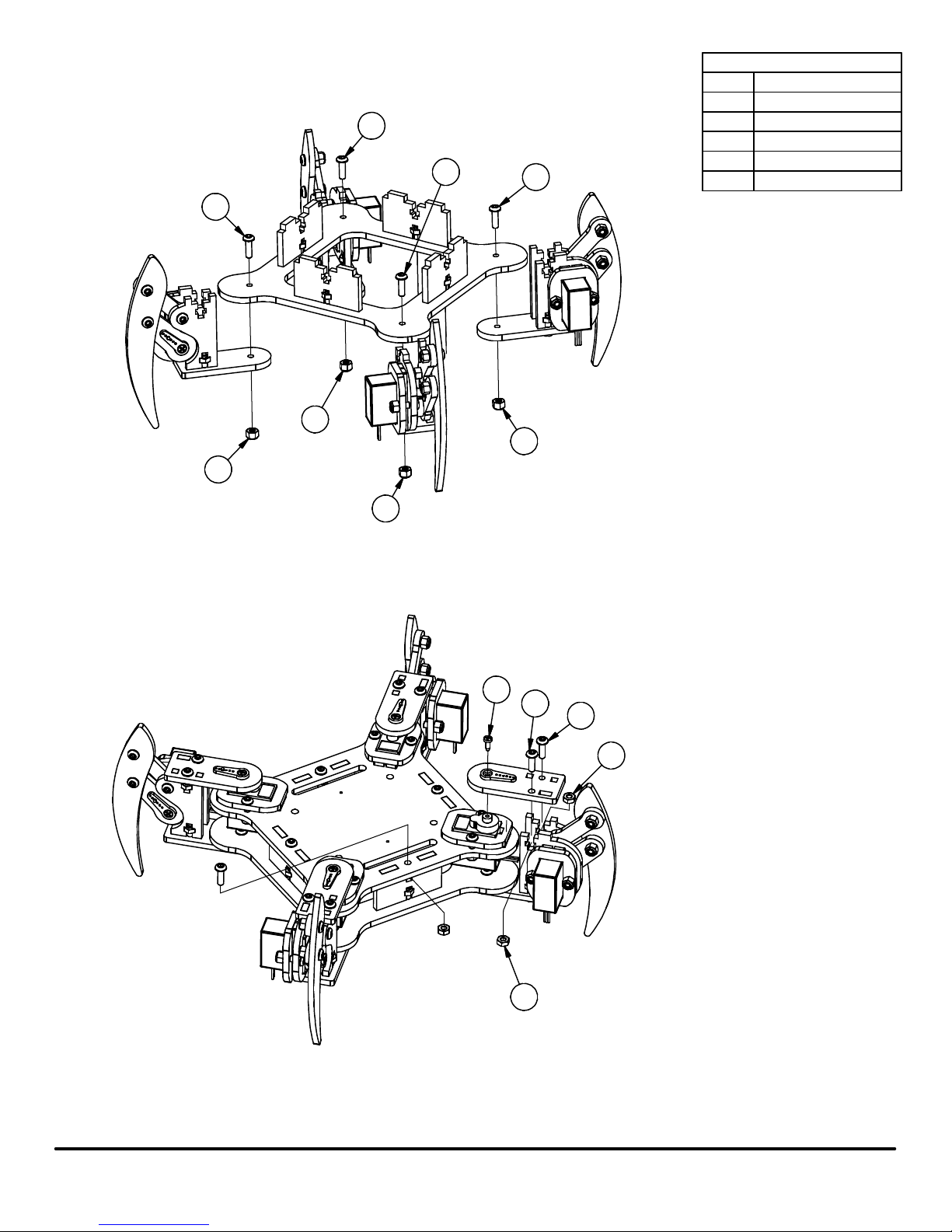
Final Assembly
2
4
PARTS LIST
PART NUMBERITEM
Servo Screw1
4
M3 x 10mm Screw2
M3 Plain Nut3
M3 Nyloc Nut
Leg, Rev A20
2
2
4
4
2
4
Step 15: Attach each Leg Assembly to the Body Bottom Plate Assembly using an M3 x 10mm
Screw and an M3 Nyloc Nut. Do not over tighten these screws. The leg joints should
move freely to prevent excess friction which could cause the servos to fail.
1
2
2
3
mePed v2 Assembly Manual v1.0
3
Step 16: Attach the Body Bottom Plate Assembly to the Body Top Plate Assembly using four
M3 x 10mm Screws and four M3 Plain Nuts.
Step 17: Rotate each Leg so they are oriented at a 45° angle as shown. Attach a Leg Top Pivot Plate
Assembly to each Pivot Servo and Leg Assembly using two M3 x 10mm Screws and two
M3 Plain Nuts.
Step 18: Secure the Servo Single Arm to the Servo using a Servo Screw.
6
www.meped.io
Page 7
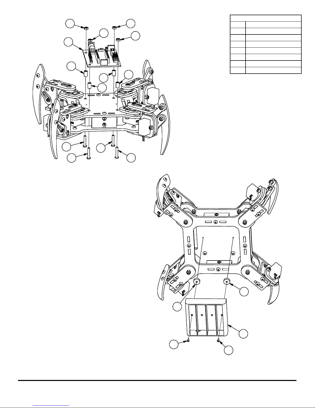
22
24
24
24
PARTS LIST
33
3
3
24
3
PART NUMBERITEM
M3 Plain Nut
Servo Mount Screw19
Battery Holder21
mePed Circuit Board22
Spacer, M3 x 8mm24
M3 x 16mm Screw25
Battery Tray Spacer26
25
25
Step 19: Attach the mePed Circuit Board to the Body Top Plate using four M3 x 16mm
Screws, four M3 x 8mm Spacers, and four M3 Plain Nuts.
25
25
26
mePed v2 Assembly Manual v1.0
26
21
19
19
Step 20: Attach the Battery Holder to the bottom of the Body Top Plate using
two Servo Screws and two Battery Holder Spacers. Feed the battery
cable through the back of the mePed body and plug it into the match
power socket on the mePed circuit board.
7
www.meped.io
Page 8
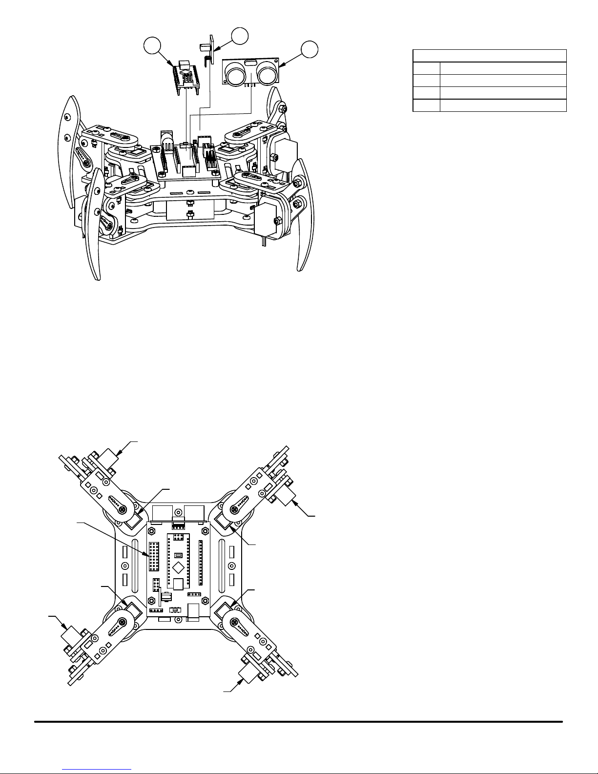
27
Step 21: Plug the HC-SR04 Ultrasonic Range Finder into the port labeled ULTRASONIC RF of the mePed Circuit Board.
Step 22: Plug the Arduino Nano micro controller into the port labeled Nano on the mePed Circuit Board. Be sure
the USB port on the Arduino Nano is facing away from the Ultrasonic Range Finder as shown in the illustration.
Failure to orient the Arduino Nano correctly can permanently damage it.
Step 23: Insert the IR Sensor into the port labeled IR on the mePed Circuit Board. Be sure to orient the IR
Sensor as shown. The pin labeled "S" on the IR Sensor should plug into the socket lableled SIG on the mePed
Circuit Board.
28
23
23
HC-SR04 Ultrasonic Range Finder
27
Arduino Nano
IR Sensor28
PARTS LIST
PART NUMBERITEM
Servo Ports
S4
S3
S2
S1
S6
S5
S7
Step 24: Plug the servos into the Servo Ports as follows:
NOTE: The Orange wire of the servo goes to the
S8
S terminal and the Brown wire goes to "-" terminal
on the mePed Circuit Board.
Front Left Pivot Servo into S1
Front Left Lift Servo into S2
Back Left Pivot Servo into S3
Back Left Lift Servo into S4
Back Right Pivot Servo into S5
Back Right Lift Servo into S6
Front Right Pivot Servo into S7
Front Right Lift Servo into S8
S9 is intentionally left empty but can
accomodate an extra servo for added customization.
mePed v2 Assembly Manual v1.0
8
www.meped.io
Page 9
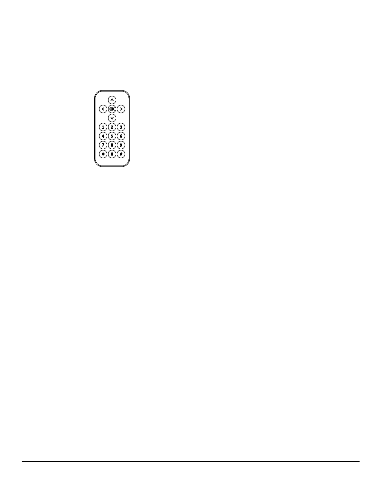
After your mePed robot is fully assembled and all the servo motor wires are plugged into their corresponding pins, insert four AA batteries
into the battery holder on the bottom side of the robot and use the power switch to turn the robot on.
Here is a list of the pre-programmed remote control functions that are already on your mePed robot.
Up - Walk Forward
IR Remote
Buttons that do not have a movement associated with them are intentionally left un-programmed so you can program your own custom
functions.
You can download the starter program already loaded onto your mePed as well as find other resources for your new robot at
www.meped.io/mepedv2.
Down - Walk Backwards
Left - Turn Left
Right - Turn Right
OK -
1 - Walk Turn Walk
2 - Wave
3 - Increase Walking Speed
4 -
5 -
6 - Decrease Walking Speed
7 -
8 - Dance
9 -
0 - Move all servos to center position
* - Trim Left
# - Trim Right
mePed v2 Assembly Manual v1.0
9
www.meped.io
 Loading...