

SpiderCloud® Radio Node - SCRN-310
®
Hardware Installation Guide
Part number: DOC-SCRN-310-HW-01, Rev. 0.1 DRAFT
Published: February 2014
FCC Statements
Caution: Any changes or modification cautions to this device not explicitly approved by manufacturer could void your
authority to operate this equipment.
This equipment complies with FCC radiation exposure limits set forth for an uncontrolled environment. This equipment
should be installed and operated with minimum 20 cm between the radiator and your body. This transmitter must not
be collocated or operating in conjunction with any other antenna or transmitter unless authorized to do so by the FCC.
Revision History
Revision Date Summary of Changes
0.1 2/19/2014 Initial draft document release
Legal Notice
Customer agrees that the Software, including the specific design and structure of individual programs, and
the Documentation are protected by United States and foreign copyright and trade secret laws. Customer
agrees not to reproduce, disclose, alter, provide or otherwise make available such trade secrets or
copyrighted material in any form to any third party without the prior written consent of SpiderCloud
Wireless. Customer agrees to implement reasonable security measures to protect such trade secrets and
copyrighted material at least to the extent that Customer protects its own information of a similar nature.
The information contained herein is subject to change without notice. Although all information is believed to
be accurate at the date of publication, SpiderCloud assumes no responsibility for inaccuracies contained
herein.
Copyright © 2014 SpiderCloud Wireless, Inc. SpiderCloud Wireless is a registered trademark and
SmartCloud a trademark of SpiderCloud Wireless, Inc. All rights reserved.
SpiderCloud Wireless
408 East Plumeria Drive
San Jose, CA 95134, USA
http://www.spidercloud.com
Tel: +1 408 567-9165
Email: info@spidercloud.com
2

Table of Contents
About this Manual . . . . . . . . . . . . . . . . . . . . . . . . . . . . . . . . . . . . . . . . . . . . . . . . . . . . . . . . . . . 5
System Overview . . . . . . . . . . . . . . . . . . . . . . . . . . . . . . . . . . . . . . . . . . . . . . . . . . . . . . . . . . . . 5
Radio Node Features . . . . . . . . . . . . . . . . . . . . . . . . . . . . . . . . . . . . . . . . . . . . . . . . . . . . . . 6
Radio Node System Isometric Top View and Bottom View. . . . . . . . . . . . . . . . . . . . . . . . . . 6
System Specifications. . . . . . . . . . . . . . . . . . . . . . . . . . . . . . . . . . . . . . . . . . . . . . . . . . . . . . . . 7
Frequency Bands of Operation . . . . . . . . . . . . . . . . . . . . . . . . . . . . . . . . . . . . . . . . . . . . . . . 7
Size and Dimensions. . . . . . . . . . . . . . . . . . . . . . . . . . . . . . . . . . . . . . . . . . . . . . . . . . . . . . . 7
Environmental Requirements . . . . . . . . . . . . . . . . . . . . . . . . . . . . . . . . . . . . . . . . . . . . . . . . 7
Power . . . . . . . . . . . . . . . . . . . . . . . . . . . . . . . . . . . . . . . . . . . . . . . . . . . . . . . . . . . . . . . . . . 8
Compliance . . . . . . . . . . . . . . . . . . . . . . . . . . . . . . . . . . . . . . . . . . . . . . . . . . . . . . . . . . . . . . 8
Radio Node Models . . . . . . . . . . . . . . . . . . . . . . . . . . . . . . . . . . . . . . . . . . . . . . . . . . . . . . . . . . 8
Antennas. . . . . . . . . . . . . . . . . . . . . . . . . . . . . . . . . . . . . . . . . . . . . . . . . . . . . . . . . . . . . . . . . . . 9
SpiderCloud Radio Node - SCRN-310 Hardware Installation Guide
Ports . . . . . . . . . . . . . . . . . . . . . . . . . . . . . . . . . . . . . . . . . . . . . . . . . . . . . . . . . . . . . . . . . . . . . . 9
The Top-Panel LED . . . . . . . . . . . . . . . . . . . . . . . . . . . . . . . . . . . . . . . . . . . . . . . . . . . . . . . . . . 9
Input Power . . . . . . . . . . . . . . . . . . . . . . . . . . . . . . . . . . . . . . . . . . . . . . . . . . . . . . . . . . . . . . . . 10
Select the Radio Node Location . . . . . . . . . . . . . . . . . . . . . . . . . . . . . . . . . . . . . . . . . . . . . . . . 11
Installation and Mount Bracket Assembly. . . . . . . . . . . . . . . . . . . . . . . . . . . . . . . . . . . . . . . . 12
Bracket Mounting and Cabling Guidelines . . . . . . . . . . . . . . . . . . . . . . . . . . . . . . . . . . . . . . 13
Typical Radio Node Mounting Options . . . . . . . . . . . . . . . . . . . . . . . . . . . . . . . . . . . . . . . . . 13
Installing the Radio Node . . . . . . . . . . . . . . . . . . . . . . . . . . . . . . . . . . . . . . . . . . . . . . . . . . . 13
Installing the Radio Node (Method 1) . . . . . . . . . . . . . . . . . . . . . . . . . . . . . . . . . . . . . . . . . . 13
Installing the Radio Node (Method 2) . . . . . . . . . . . . . . . . . . . . . . . . . . . . . . . . . . . . . . . . . . 15
Completing the Installation . . . . . . . . . . . . . . . . . . . . . . . . . . . . . . . . . . . . . . . . . . . . . . . . . . 17
Detaching the Radio Node from the Mount Bracket . . . . . . . . . . . . . . . . . . . . . . . . . . . . . . . 17
Boot Sequence and Services Node Communication . . . . . . . . . . . . . . . . . . . . . . . . . . . . . . . 18
Radio Node LED Boot Sequence . . . . . . . . . . . . . . . . . . . . . . . . . . . . . . . . . . . . . . . . . . . . . . . 19
Radio Node LED Management . . . . . . . . . . . . . . . . . . . . . . . . . . . . . . . . . . . . . . . . . . . . . . . . . 20
The SpiderCloud Documentation Set . . . . . . . . . . . . . . . . . . . . . . . . . . . . . . . . . . . . . . . . . . . 22
Appendix A UMTS Antenna Patterns . . . . . . . . . . . . . . . . . . . . . . . . . . . . . . . . . . . . . . . . . 23
Appendix B LTE Antenna Patterns . . . . . . . . . . . . . . . . . . . . . . . . . . . . . . . . . . . . . . . . . . 27
SpiderCloud Wireless, Inc.
3

Contents
4
SpiderCloud Wireless, Inc.
SpiderCloud Radio Node - SCRN-310 Hardware Installation Guide
LAN Intranet
DMZ
Enterprise
Mobile
Operator Core
Email Web
Radio Nodes
SGSN
MSC
IPsec
Backhaul
IPsec
Switch
Firewall
Security
Gateway
Services
Node
Iu-CS
Iu-PS
IPsec
HNB
Gateway
Iuh
SGW
MME
UMTS
LT E
S1-C
S1-U
3G/LTE
S1
About this Manual
This guide provides the system specifications of the SpiderCloud® Radio Node 310 (SCRN-310). It
includes detailed hardware installation instructions, the boot sequence, and expected LED behavior both
during the boot-up and under operating conditions. An appendix shows the radio node antenna patterns.
The primary audience for this guide includes network planners, system administrators and installation
personnel. It assumes you have knowledge about networking principles, networking configuration, site
preparation, powering, and experience in hardware installation and maintenance.
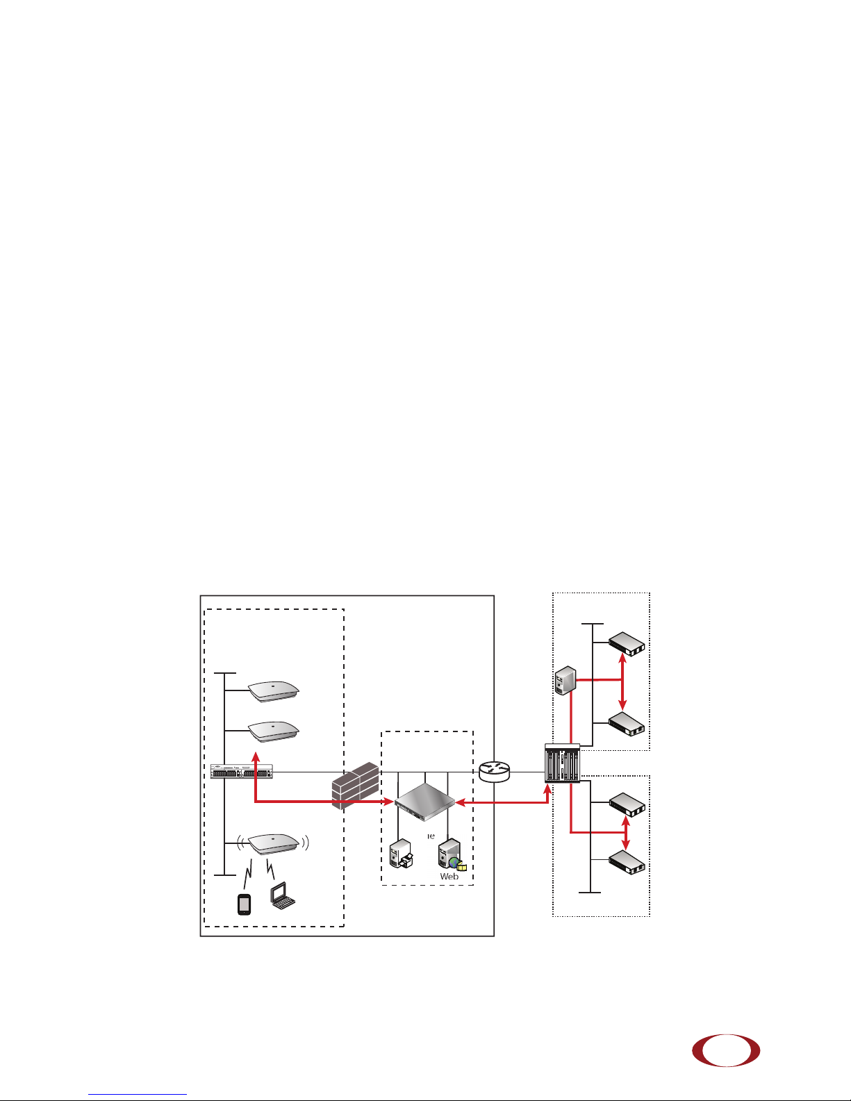
System Overview
The SCRN-310 is an indoor multi-access small cell capable of supporting Universal Mobile
Telecommunications System (UMTS) and Long Term Evolution (LTE) radio protocols concurrently in a
single platform. The radio node is 3GPP compliant, supporting UMTS Release 7 and LTE Release 9
standards.
Each radio node supports:
• up to 32 simultaneous UMTS voice and data channels, a peak downlink rate of 21 Mbps and a
peak uplink rate of 5 Mbps.
• up to 32 active LTE users, a peak download rate of 100 Mbps, and a peak upload of 50 Mbps
when used with 20 MHz channel bandwidth.
The radio node enables mobile operators to offer dedicated, in-building coverage and capacity for UMTS
and LTE services. It is easy to install and connects to the existing enterprise LAN using standard Ethernet
cabling or to a dedicated LAN infrastructure deployed for use by the operator. SCRN-310 radio nodes are
managed by the SpiderCloud SCSN-9000 services node access controller, typically installed in the
enterprise DMZ.
Figure 1 Radio Node Relationship to Enterprise and Mobile Operator Core Networks
SpiderCloud Wireless, Inc.
5

SpiderCloud Radio Node - SCRN-310 Hardware Installation Guide
Radio Node Features
The radio node supports the following features:
• Complete enterprise mobility using licensed 3G and LTE spectrum
• Self Organizing Network (SON) capabilities for autonomous setup, operation, and management
• Secure boot
• Transparent integration into enterprise network environments
• Certificate-based authentication with the SpiderCloud services node
Radio Node System Isometric Top View and Bottom View
The radio node ships with four internal antennas. The following drawings display an isometric top and
bottom views of the radio node:
Figure 2 Radio Node Top View
Figure 3 Radio Node Bottom View with Pedestal Base
6
SpiderCloud Wireless, Inc.

SpiderCloud Radio Node - SCRN-310 Hardware Installation Guide
System Specifications
Following are the system specifications for the radio node frequency bands of operation, system size,
environmental requirements, power, and compliance.
Frequency Bands of Operation
SpiderCloud Wireless currently provides two versions of the SCRN-310 for operation in the following
UMTS and LTE band combinations. Note that the SCRN-310 hardware is also capable of supporting two
carriers of LTE (feature available in a future software upgrade).
• SCRN310-0701
— Operates in Band Class 1 (UMTS)
— Operates in Band Class 7 (LTE)
— Monitors GSM 900/1800 MHz, UMTS 2100/900 MHz, LTE 2600/1800/800 MHz
• SCRN310-0402
— Operates in Band Class 2 (UMTS)
— Operates in Band Class 4 (LTE)
— Monitors GSM 850/1900 MHz, UMTS 2100/1900/850 MHz, LTE 2100/700 MHz
Size and Dimensions
• Height:
— 5.3 centimeters (2.1 inches)
— 11.3 centimeters including mount bracket assembly (4.4 inches)
• Width: 20.6 centimeters (8.1 inches)
• Length: 23.9 centimeters (9.4 inches)
• Weight:
— 1.2 kilograms (2.6 pounds)
— 1.41 kilograms with mounting bracket (3.1+ pounds)
Environmental Requirements
• Operating temperature range:
— 0° to 50° C (32° to 122° F) vertical mount
— 0° to 40° C (32° to 104°F) horizontal mount, fins up
• Operating humidity: 0 to 90% non-condensing
• Storage temperature range: 0° to 85° C (-40° to 185° F)
• Storage humidity: 0 to 90% non-condensing
• Ingress protection rating: IP30
SpiderCloud Wireless, Inc.
7

SpiderCloud Radio Node - SCRN-310 Hardware Installation Guide
Power
The radio node is compliant with IEEE 802.3at (PoE+):
• Power consumption: 23W maximum
• UMTS transmitter output power: 1x 250 mW (24 dBm) RMS radio power
• LTE transmit output power: 2x125 mW (24 dBm)
Compliance
•ETSI:
— EN 301 489-1
— EN 301 489-23
— EN 301 908-1
— EN 301 908-3
— EN 50385
— EN 60950-1 (safety)
• IEEE 802.3at PoE+
• FCC:
— FCC Part 15 Class A
— FCC Part 24 (UMTS Band II only)
— FCC Part 27 (UMTS Band IV only)
•CE Marking
• NRTL Marking
• RoHS (Directive 2002/95/EC on RoHS)
• R&TTE (Directive 1999/5/EC on R&TTE)
• CB certification as per IEC 60950-1:2011
Radio Node Models
Ta bl e 1 displays the orderable configurations of the SCRN-310 radio node:
Table 1: SCRN-310 Radio Node Configurations
Radio Node Model Description
SCRN-310-0701 Dual-mode with internal antennas: LTE Band 7, UMTS Band 1
SCRN-310-0402 Dual-mode with internal antennas: LTE Band 4, UMTS Band 2
8
SpiderCloud Wireless, Inc.

SpiderCloud Radio Node - SCRN-310 Hardware Installation Guide
Ethernet
Port
Link
Activity
LED
Antennas
The radio node includes four integrated antennas: two UMTS antennas and two LTE antennas. The UMTS
radio operates in 1x2 mode with receive diversity. The LTE radio operates in 2x2 mode with MIMO.
Tip: To maximize antenna transmission, SpiderCloud Wireless recommends not installing the radio node
inside a metallic enclosure.
Ports
The radio node has one 1 Gigabit Ethernet port that supports a Category 5e (Cat 5e) or better twisted-pair
cable with an RJ-45 connector.
• Link: Steady green state indicates a normal Layer 2 link connection has been established.
• Activity: Yellow blinking indicates data activity.
Figure 4 shows the Ethernet port. There are two LEDs on the connector:
Figure 4 Ethernet Port
The Top-Panel LED
The radio node has one top-panel tricolor LED to indicate power and status. This is the only LED visible
under normal operating conditions. When the radio node initially boots the LED cycles through a number of
colors and flashing behaviors until it is fully operational.
Figure 5 Radio Node Tricolor LED
SpiderCloud Wireless, Inc.
9

SpiderCloud Radio Node - SCRN-310 Hardware Installation Guide
Services Node
PoE+ Switch
Out
In
Services Node
PoE+ Switch or
PoE+ Injector
PoE+ Injector
Non PoE+ Switch
Input Power
The radio node receives its power from a standard PoE+ switch (typical) or injector. The radio node is fully
compliant with the IEEE 802.3at Power Over Ethernet (PoE+) specification.
Per IEEE 802.3at, use standard Cat 5e or better twisted-pair cable with a maximum length restriction of
100 meters (328 feet) for PoE+. This restriction minimizes power loss between the PoE+ power source
and the radio node.
Power is distributed over two pairs of the four available pairs in Cat 5e or better cables. The radio node can
accept power on either used or un-used pairs.
Figure 6 on page 10 shows the valid radio node cabling/powering options:
The illustration below shows a generic single-port PoE+ injector. Use this injector only when a PoE+
Ethernet switch is not available.
To connect the PoE+ injector to a radio node
Figure 6 Valid Radio Node Cabling/Powering Options
CONNECT
PoEPLUS
OUT
ON
IN
Figure 7 Typical PoE+ Injector
Step 1 Attach the injector power cord to a power source.
Step 2 Connect an unpowered Ethernet cable from a switch to the IN port on the injector.
10
SpiderCloud Wireless, Inc.

SpiderCloud Radio Node - SCRN-310 Hardware Installation Guide
Dead / Non-Circulating
Airspace
Living / Working Space of a Typical
Commercial Building
Drop Ceiling
Wall
Forced-Air Supply
Forced-Air Return
X
X
Step 3 Connect an Ethernet cable from the injector’s OUT port to the radio node. The injector will
now inject power onto a pair of wire pairs in the cable. The radio node will expect a
nominal 48V DC input (57V max) from a typical PoE+ injector.
Select the Radio Node Location
Radio nodes can be installed in a wide range of locations including walls, ceilings, and plenum spaces.
Follow the installation guidelines for selecting appropriate mounting locations for the unit. When mounting
a radio node vertically, align the bottom-side fins vertically for superior cooling.
When possible, locate radio node units at least 5 meters (16 feet) from an external wall. This distance
maximizes indoor coverage and minimizes RF leakage outside the building. When mounting near a wall or
other obstruction, orient the mounting bracket such that the transmit antenna faces towards the coverage
area and faces away from the wall. Refer to
more information.
SpiderCloud Wireless, Inc.
Figure 8 Radio Node Locations
Bracket Mounting and Cabling Guidelines on page 13 for
11

SpiderCloud Radio Node - SCRN-310 Hardware Installation Guide
Table 2 to determine the maximum distance between radio node units. Greater separation may affect
Use
coverage or system performance.
Table 2: Recommended Radio Node Separation Distances
Type of Building Max Recommended Separation
Warehouses and large open-spaced buildings 70 m (230 feet)
Open-plan offices 45 m (148 feet)
Closed-plan offices (e.g., individual rooms - plasterboard) 30 m (98 feet)
Closed-plan offices (e.g., individual rooms - stone/brick/concrete) 20 m (66 feet)
Installation and Mount Bracket Assembly
The radio node has a pedestal base that slides into a long bracket for ceiling or wall mounting. SpiderCloud
Wireless pre-bolts the pedestal base onto the extrusion plate on the radio node. However you must attach
the pedestal base to the mount bracket as shown in
Figure 9:
Pedestal Base
Mount Bracket
Figure 9 Pedestal Base Slides into Mount Bracket
12
SpiderCloud Wireless, Inc.

SpiderCloud Radio Node - SCRN-310 Hardware Installation Guide
Bracket Mounting and Cabling Guidelines
Incorrectly cabling and mounting a radio node can result in crushed cables and loss of communications to
the unit. Follow these guidelines in cabling the radio node and mounting it on the bracket:
• Ensure that the cabling is properly routed and dressed.
• Ensure that the pedestal base is fully inserted into the mount bracket so that it locks into place
and is flush. A correctly installed cable should at no time during installation impede inserting
the pedestal base into the mount bracket.
• Secure the pedestal base to the mount bracket with a padlock or tie wrap to provide physical
security.
• When mounting the radio node vertically, orient the bracket with the open end on top and the
closed end on the bottom.
• When mounting the radio node near a wall or other obstruction, orient the bracket such that the
radio node transmit side towards the coverage area. In vertical mountings, this is on the right
side of the radio node.
Figure 10 on page 14 shows the proper vertical orientation.
Figure 10 on page 14 shows the mounting bracket orientation.
Typical Radio Node Mounting Options
Radio nodes can be mounted on a wide number of surfaces including the following typical surfaces:
• Light grill: Use bolts, nuts, and washers to secure the mount bracket using holes in the light
grill. Adjust the mounting bracket until the bracket and light grill holes align.
• Directly on the wall or ceiling: Use drywall screws to secure the mount bracket directly to
sheetrock or plasterboard on the wall or ceiling.
• Mud or plaster ring: Secure the mount bracket directly on the wall or ceiling as above with a
3 1/4 inch (8.25 centimeter) mud or plaster ring between the mount bracket and the mounting
service and run the Ethernet cable through ring’s hole.
• Strutting: Secure the radio node to heavy hanging equipment strutting using strut clip nuts and
M8 studding.
Installing the Radio Node
The radio node receives its power source over powered Ethernet. If your wiring closet does not have
existing PoE+ equipment, SpiderCloud Wireless recommends a PoE+ power injector for the radio node.
See section
The Ethernet cable can route openly or directly through a surface such as a wall or ceiling:
• Refer to
• Refer to
Installing the Radio Node (Method 1)
To route the cable openly and mount the radio node
Input Power on page 10.
Installing the Radio Node (Method 1) on page 13 for open cable routing installation.
Installing the Radio Node (Method 2) on page 15 for direct cable routing installation.
Step 1 With two user-provided screws, attach the mount bracket assembly to a wall or ceiling. The
screw holes are sized for an M4 (#10) screw. Ensure the screws have a snug fit onto the
studs, sheetrock, anchor, or other material you are bolting onto.
SpiderCloud Wireless, Inc.
13

SpiderCloud Radio Node - SCRN-310 Hardware Installation Guide
Transmit Side
RJ-45 Connector in Ethernet Port
Cable
Opening
Cable
Guides
Spring
Clip
Figure 10 Attach the Mount Bracket
Step 2 Insert the RJ-45 connector into the Ethernet port as shown in Figure 13. Route the
Ethernet cable through the cable guides and pedestal base cable opening and through the
cable guides as shown in
Figure 11:
Step 3 Press the cable into the cable guides until the guides securely snap around the cable.
Ensure that there is no cable slack and that there is sufficient cable bend radius.
Step 4 Slide the pedestal base of the radio node into the groove opening in the mount bracket.
When the pedestal reaches the end of the trough, a spring clip will secure the unit into
place.
14
Figure 11 Route and Terminate the Cable
SpiderCloud Wireless, Inc.
 Loading...