

SpiderAlert SR-500, SR-500 ER Installation Instructions Manual
DE3211 3-11
SR
SRSR
SR-500
-500-500
-500, SR
, SR, SR
, SR-500
-500-500
-500 ER
ER ER
ER
SpiderAlert Wireless Receiver
Installation Instructions
1111. INTRODUCTION
. INTRODUCTION. INTRODUCTION
. INTRODUCTION
SR-500 wireless receiver is as an interface unit between various
SpiderAlert wireless transmitters and the SpiderBus.
SR-500 ER is the extended range version of the SR-500. It has
the following features:
• Higher receiver sensitivity that enables longer communication
range.
• Improved receiver selectivity (narrower bandwidth) that
prevents reception of interfering signals from undesired
transmitters (whose frequencies are near the receiving
frequency).
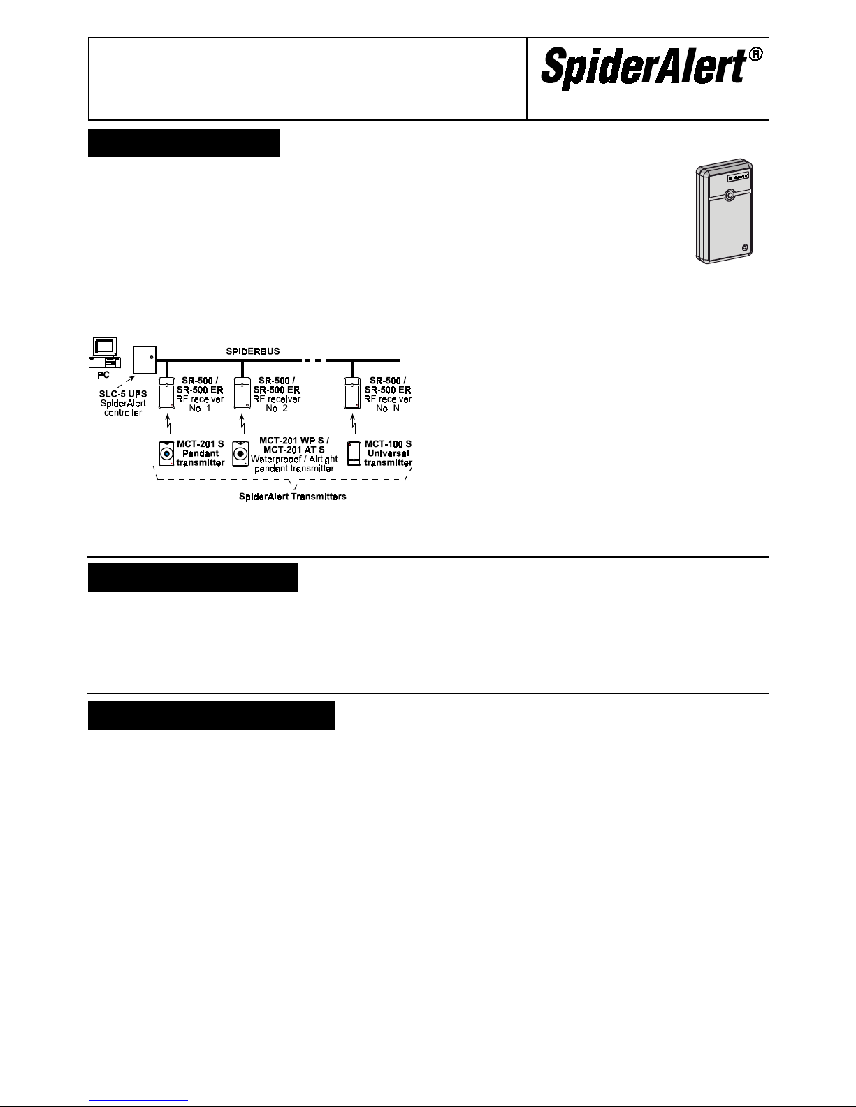
SR-500 (ER) receives RF signals from SpiderAlert transmitters
and relay the signals to the SpiderAlert Local Controller SLC-5
via the SpiderBus. All data collected by the SLC-5 is transferred
to the head end computer for further processing (see fig. 1-1).
Figure 1-1. SR-500 (ER) in the SpiderAlert System
Each receiver has a factory-programmed, 8-bit ID number (in a
2-digit hexadecimal form) that is marked on top of its
microprocessor IC.
Attendance reports with the receiver ID
number are sent by each receiver to the
SLC-5 at regular intervals, thus permitting
continuous supervision over the entire
receiver network (see Para. 3-2).
SR-500 (ER) also responds to command
signals sent from the computer via the SLC-5
controller and SpiderBus. Each command
signal is addressed to a specific receiver, for
controlling one of its two output circuits.
Figure 1-2.
External View
This allows the attendant at the head end to control remote
equipment such as sirens, lights or automatic voice announcers,
that can be turned on and off by direct connection to receiver’s
output or via a relay.
The receiver can be remotely programmed from the SpiderAlert
main station - programming of the receiver ID number and the
duration of its outputs 1 and 2 signals in “pulse” operation mode.
The receiver is protected against tampering by an on board
tamper switch that is actuated upon removal of the front cover.
Once tampered with, the receiver sends out its ID code plus a
special tamper code to the head end computer.
A sensitivity control (marked RANGE, see fig. 4.3) is provided on
the printed circuit board, to enable reception range adjustment.
A terminal block at the top (see fig. 4.3) provides a 4-wire
connection to the SpiderAlert bus and two output terminals for
controlling external devices (for details, refer to para. 3-3). A
right-hand side terminal block (fig. 4.3) provides 3 input terminals
for reporting local alarms (for details, refer to para. 3-4).
When a deliberate (or accidental) jamming signal is received, the
receiver sends a jamming alert message.
2222. SPECIFICATIONS
. SPECIFICATIONS. SPECIFICATIONS
. SPECIFICATIONS
Operating Frequency (MHz): 315, 404, 418, 433.92 or other
frequencies according to local requirements.
Receiver ID Code: 1 of 255 possible codes, factory programmed
Data Transfer to Bus: Serial, software controlled.
Operating Voltage Range: 10 - 16 VDC.
Number and type of Inputs: 3, Normally closed (NC)
Number of Outputs: 2
Open Collector Output Current Sinking Capability: 100 mA.
Current Consumption @ 13.6 V:
SR-500: 7.2 mA (Standby), 8.8 mA (in operation)
SR-500 ER: 37 mA (standby), 39 mA (in operation)
Operating Temperature Range: 0°C to 49°C (32°F to 120°F).
Dimensions (H x W x D):
110 x 63 x 25 mm (4-5/16 x 2-1/2 x 1 in.)
Weight: SR-500 - 80g (2.8 oz.), SR-500 ER - 78g (2.75 oz.)
3333.
. .
. OPERATION ROUTINE
OPERATION ROUTINEOPERATION ROUTINE
OPERATION ROUTINE
3.1 Message Handling
When a coded message is received from SpiderAlert transmitter,
the receiver registers it and checks whether the bus is busy. If so,
the receiver pauses to prevent collision of its message with other
messages, and then tries again. If the bus is free, the receiver
reports the transmitter's ID code, be it 12-bit or 24-bit,
accompanied by its own 8-bit ID number.
Once the message is received by the SLC-5, an "acknowledge"
signal is returned to the receiver, causing it to stop sending the
data. If there is no response from SLC-5, the receiver will keep
sending the data repeatedly, until SLC-5 returns an
acknowledgement. The receiver will not be free to receive new
coded transmissions until it gets this acknowledgement.
A special on-board LED lights upon reception of a valid RF
signal. It will remain illuminated while the receiver is engaged in
sending the message via the data bus or while the receiver is
waiting for an acknowledge signal from SLC-5. The LED turns off
5 seconds after reception of acknowledge signal from the SLC-5.
3.2 Supervision Method
The receiver is programmed to send out periodic attendance
messages. An attendance message consists of the receiver's ID
number and a special test code identifying the message as an
attendance report. Once the SpiderAlert network is powered up,
all receivers on the bus go through the first cycle of attendance
reports. The SLC-5 automatically "learns" the participating units'
ID numbers, registers their IDs and creates a supervision list.
After the first reporting cycle, the SLC-5 will expect regular
attendance reports from each unit on its list.
Attendance reports received at regular (correct) intervals are
acknowledged by the SLC-5 but not displayed by the head end
computer. However, attendance reports received for the first time
or after a break in communication between the receiver and the
SLC-5 will be displayed on the head end computer screen.
If an attendance report from a specific receiver fails to come in
within 4 minutes from the last report, a warning appears on the
computer's monitor. If attendance reports from a certain receiver
or from a group of receivers stop, the reason might be SpiderBus
discontinuity (an "open" bus), receiver failure or sabotage.
3-12 DE3211
3.3 Output Control
The SR-500 (ER) provides two output terminals (OUT1 and
OUT2). These terminals, that are of the open-collector type, are
under control of the head-end software - they can be activated
(pulled LOW) and deactivated manually or by automatic computer
command. Each output may be used to sound an alarm, to switch
lights on and off, to open a door controlled by an electrical door
strike, or for many other tasks. Since each open collector output
can not sink more than 100 mA, an interface relay might be
required for operating external devices, as shown in Figure 4-4.
3.4 Reporting Local Alarms
The SR-500 (ER) provides 3 input terminals with a common
ground return on a separate terminal block. The input circuits,
which are of the normally closed type, may be connected to
motion, smoke or glass break detectors in the immediate vicinity
of the unit for reporting local alarms via the SLC-5 to the
head-end computer. The computer software identifies the
receiver that sent out the alarm signal and the specific input of
origin. Consecutively, a suitable message appears on the
computer's monitor and the alarm is registered in the event log.
4444. INSTALLATION
. INSTALLATION. INSTALLATION
. INSTALLATION
4.1 Preliminary Survey
Taking into account that the coverage
areas of individual receivers should
overlap a little, to prevent creation of
"dead" spots in-between neighbouring
units. It is therefore recommended to
conduct a survey of the installation
site as follows:
A. Prepare a test equipment set
consisting of an SLC-5, several
SR-500(ER) receivers, a power
supply unit, a 4-lead cable reel
and at least one type of
transmitter.
Note: Make sure the sensitivity
control in each receiver is set
halfway between MAX. and MIN.
Depress the tamper switch lever
and capture it in this position with
masking tape.
B. Place the SLC-5 in a convenient
location and temporarily deploy a
few receivers at "strategic"
reception points throughout the
coverage area.
Figure 4-1.
Temporary Bus
C. Use the 4-lead cable to form a temporary bus that inter
connects all receiver units and SLC-5, as shown in Fig. 4-1
(also refer to Para. 5-1, Steps A and B). The cable may be
put down on the floor, following the shortest possible path.
D. Power up the test equipment using the 12 VDC power supply
or a 12 V battery (see Figure 4-1).
E. Operate a SpiderAlert transmitter in various locations within
the receiver's expected coverage area to test the reception
range. Reception is verified when the LED lights steadily in
response to each transmission, until the SLC-5 acknowledges
the message.
IMPORTANT: Remember that different transmitter models
have different power outputs. It is therefore advisable to
make this test with all transmitter models likely to be used in
the vicinity of the tested receiver.
F. If "dead" or marginal reception areas are discovered:
• Move the receiver to a point where reception is better.
• Rotate the sensitivity control towards MAX to increase the
receiver's sensitivity.
• Move the neighboring receiver closer, to bridge the
reception gap.
G. If the receiver is picking up transmissions made in a
neighboring area:
• Move the receiver away from the neighbouring area to
decrease the coverage overlap.
• Rotate the sensitivity control towards MIN to decrease the
receiver's sensitivity.
• Coil the antenna wire (use a small screwdriver's stem for
forming the coil) to reduce the reception range.
H. Repeat Steps E through G above for all other receivers.
Make a list of the chosen locations and indicate special
requirements (sensitivity control position, coiled antenna, etc.).
Note: To determine the point from which an alert transmission
was made with greater accuracy, dual technology (RF/IR)
receivers and transmitters should be used. This especially
applies to multi-story buildings.
4.2 Mechanical Mounting
Note: If it is necessary to install the receiver in a metal
enclosure, let the antenna wire out through a hole or a slot in the
metal enclosure, and test the reception ability very carefully.
A . Open the receiver box.
B . Open the two mounting
knockouts in the base.
C. Hold the base, against the
mounting surface, with the
antenna wire hanging
down.
D . Mark points for drilling, put
the unit aside and drill the
mounting holes. Attach the
unit to the mounting surface
using two screws and wall
anchors (if required).
Knockouts that serve as
wiring outlets are provided
at the top of the base.
SR-500(ER) may be connected
to the SpiderBus via 4
terminals (Fig. 4-4) or via
telephone type RJ-11
connector.
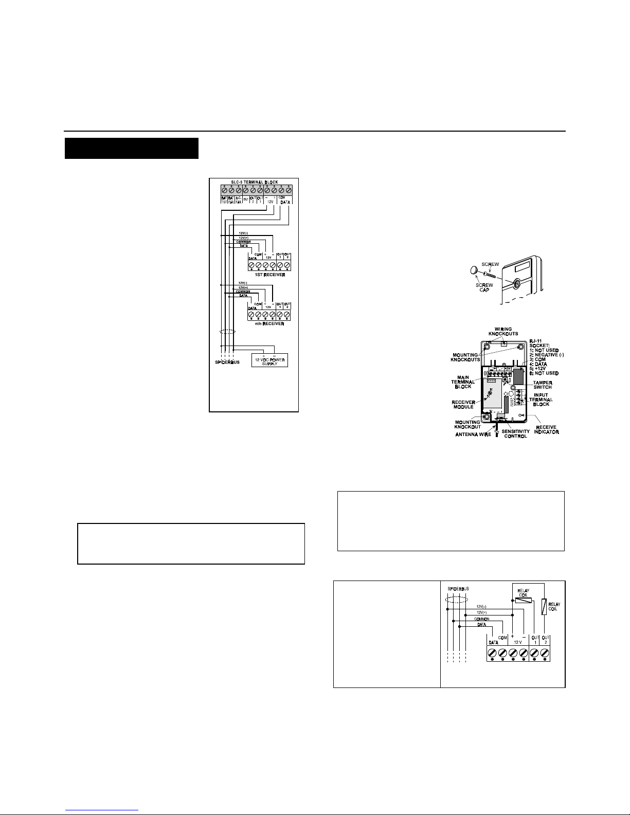
Figure 4.2 Cover Removal
Figure 4.3 Internal View
4.3 Terminal Block Wiring
A. Connect the data wires of the bus to the DATA terminals on
the receiver's terminal block.
CAUTION! One of the data terminals is marked COM,
indicating connection to the common (negative) lead of the
data bus. The other terminal marked DATA must be
connected to the second lead of the data bus. As long as the
data bus is free, the data lead is kept HIGH by a pull-up
resistor in the SLC-5 Local Control Unit.
B. Connect the power supply bus wires to the 12 V(+) and (–)
terminals.
Caution: Make sure not to reverse the bus wires!
Attention! With a large
number of receivers on the
bus, individual power
supplies may be used for
each group of receivers.
Refer to Para. 4-4 in SLC-5
installation manual
(D-7115-0), where several
examples are given for
power supply distribution
along the bus.
Figure 4-4. Bus, Power and
Output Terminal Block Wiring
Auxiliary power supply PS-2 and bus repeater SRP-51 are
available for long buses (refer to installation manuals).
C. Either output terminal is suitable for operating a low-current
12VDC buzzer, an LED, or an auxiliary relay that draws less
than 100 mA current. In case of a relay, connect its operating
 Loading...