

Page 1
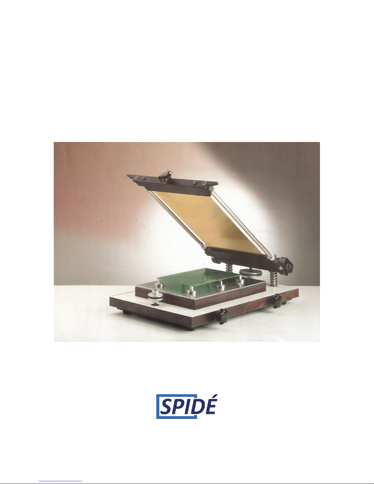
SP912 M1
STENCIL PRINTER
User manual
Version 2.10
Page 2

Manual stencil printer SP912 M1 Rev.2.1
Made in the Netherlands by Spidé January 1st, 2015 1
Table of contents
IMPORTANT SAFETY RULES ..................................................................................................................... 2
Introduction ............................................................................................................................................. 2
Setting up the stencil printer ................................................................................................................... 2
Placement of the stencil printer .............................................................................................................. 3
The SP912 M1 overview .......................................................................................................................... 4
Getting started ........................................................................................................................................ 5
Installing the stencil............................................................................................................................. 5
Installing the first PCB ......................................................................................................................... 5
Operating the stencil printer ................................................................................................................... 6
Maintenance and care ............................................................................................................................. 6
Cleaning the stencil frame ....................................................................................................................... 7
Product specifications ............................................................................................................................. 7
Warranty ................................................................................................................................................. 7
Page 3

Manual stencil printer SP912 M1 Rev.2.1
Made in the Netherlands by Spidé January 1st, 2015 2
IMPORTANT SAFETY INSTRUCTIONS
Machine location:
Do not use the printer outdoors! The printer is developed to be installed on a flat, dry
surface. This surface or table must be capable of carrying a weight of at least 10 Kg (ex. The
force used to spread the paste). The printer should be used with room temperatures
between 15 and 25 degrees Celsius.
Use the printer only in well ventilated rooms. During the printing the flux will release some
gasses. These gasses released by the flux can be unhealthy, please follow the safety
instructions of your paste supplier.
Normal use:
The printer is developed for printing paste on PCBs only. Do not use the printer for printing
on food, animals or any other materials. You will void your warranty if you do not ignore
these instructions. When used for anything other than printing paste on PCBs you will void
your warranty!
Introduction
Remark
Pictures in this manual could be different than the actual model you purchased.
They are meant to explain the printers’ use and function.
The SP912 M1 stencil printer is designed to put solder paste on PBC’s with a “stencil”. A
stencil is a thin metal sheet which has holes matching the position of the pads located on the
PCBs.
Unlike other stencil printer brands, the SP912 M1 has unique features for user friendly
handling of stencils and PCBs.
Some of the features include:
• Stencils do not need mounting holes.
• Fixing a stencil is fast, easy and requires no heating of the stencil.
• Positioning of PCBs is simple but effective.
• You may use the stencil printer for single as well as double sided PCBs. Even if there
are already components on one side!
Setting up the stencil printer
This machine is produced and packed with special care to deliver you the best quality possible. We
still advice you use extra care while unpacking the machine. After unpacking make sure to look for
any damage on the outside of the machine and immediately report it to the transport company.
If you do not make any remarks of transport damage on the freight papers, you will lose your right
to any insurance claims!
Page 4

Manual stencil printer SP912 M1 Rev.2.1
Made in the Netherlands by Spidé January 1st, 2015 3
Carefully unpack the stencil printer and keep the original package in case you need to ship the unit.
Please check to be sure the following items are included with your stencil printer:
• 1 stencil printer SP912 M1
• 3 Allen Keys, metric sizes
• 1 non-permanent fine liner marker pen
• 6 magnetic placeholders for PCBs
• 2 magnetic points of support for PCBs
• 1 transparent outline-sheet to define PCB position
• 1 squeegee
Placement of the stencil printer
Place the stencil printer on a stable, flat surface. This surface should be strong enough to carry the
weight of the machine (+/- 7Kg) including the pressure you add while spreading the flux (+/- 10Kg).
Leave a 10 cm gap free on each side of the machine for easy access to the X-axis, Y-axis and height
adjustments.
Page 5
Manual stencil printer SP912 M1 Rev.2.1
Made in the Netherlands by Spidé January 1st, 2015 4
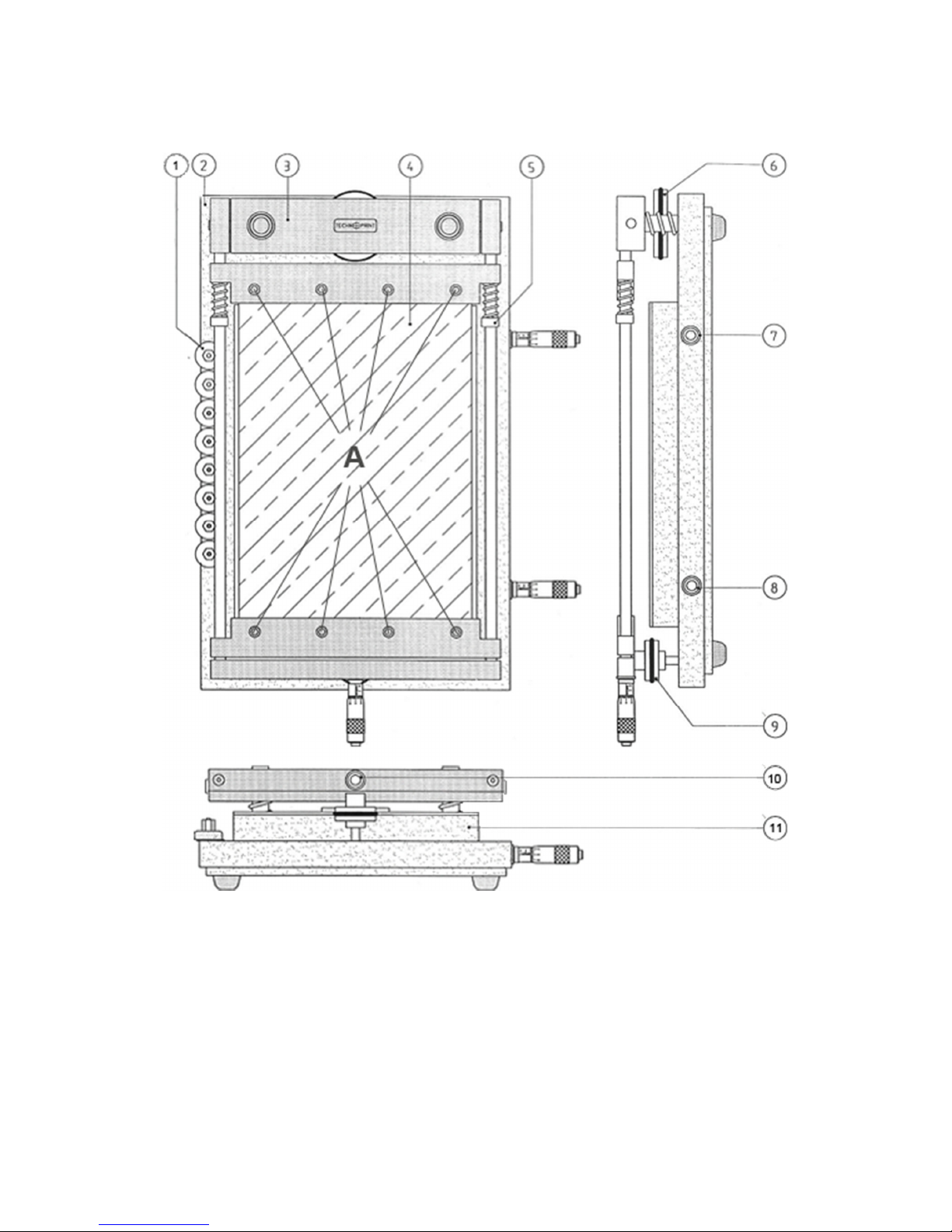
The SP912 M1 overview
1. Storage magnetic devices
2. Base plate
3. Stencil frame
4. Stencil
5. Stencil size adjustment
6. Top height adjustment of stencil
7. X-axis alignment and top rotation table
8. X-axis alignment and bottom rotation table
9. Bottom height adjustment of stencil
10. Y-Axis alignment and stencil tensioner
11. PCB table
Page 6
Manual stencil printer SP912 M1 Rev.2.1
Made in the Netherlands by Spidé January 1st, 2015 5
Getting started
Installing the stencil
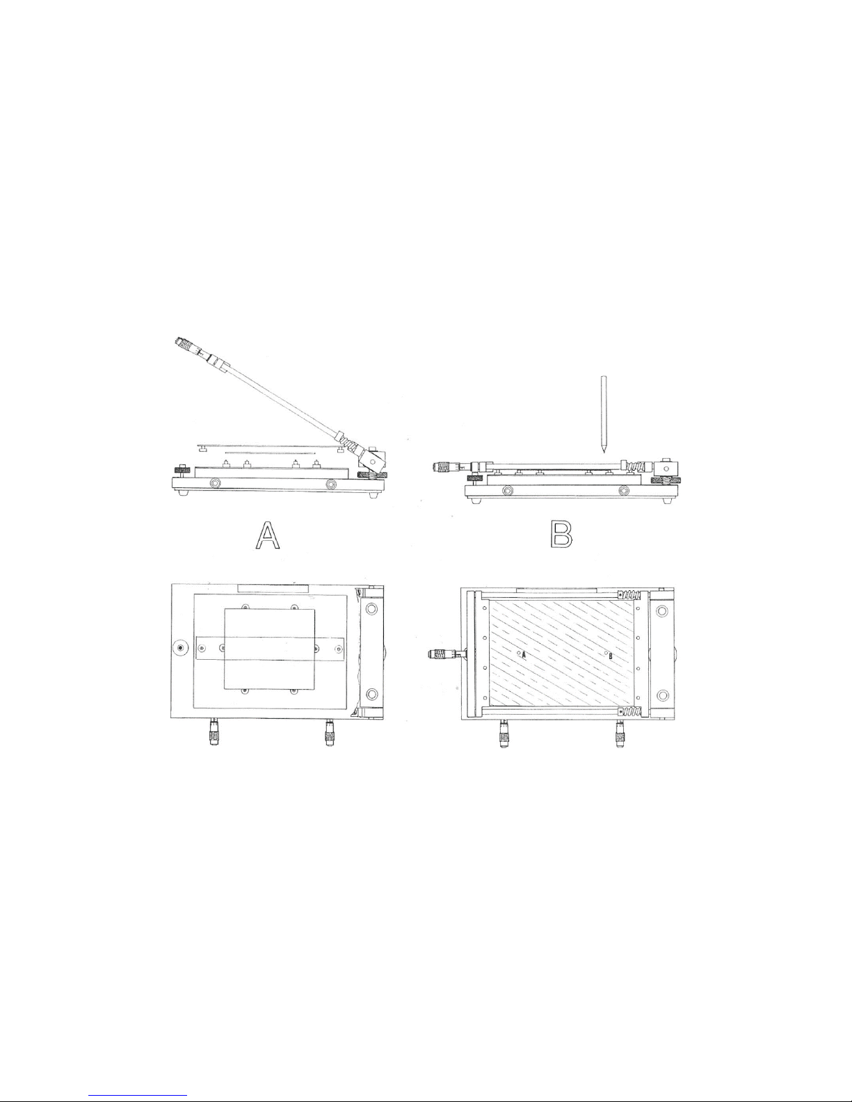
1. Loosen up the Y-axis alignment or stencil tensioner. (10)
2. Unscrew the eight screws of the stencil frame. (A)
3. Place the stencil in the first stencil holder.
4. Tighten the four screws.
5. Repeat step 1 – 4 for the second stencil holder.
6. Tighten the stencil tensioner. (10)
Installing the first PCB
1. Open the printer. (picture A)
2. Place the PCB roughly in its position with 4 to 6 magnetic placeholders.
3. For large board use the two magnetic points and place them in the middle of the PCB.
4. Place the transparent outline plate over the PCB and close the printer. (picture B)
5. Search two easy to identify holes in the stencil which are above the outline plate. Then use
the marker pen to place spots on the outline plate. After this open the printer. (picure A)
6. Adjust the PCB so that the PCB pads are at the same location as the marker points.
7. Remove the outline plate without moving the PCB and close the printer again. (picture B)
8. Use the bottom and top height controls to bring the stencil just above the PCB. Less space is
better.
9. Use the X- and Y-axis for small adjustments to align the stencil holes and PCB pads.
10. Your printer is now ready for printing!
Page 7

Manual stencil printer SP912 M1 Rev.2.1
Made in the Netherlands by Spidé January 1st, 2015 6
Operating the stencil printer
Once the installation is completed in the order described above, it is easy to place successive PCBs on
the placeholders.
BUT BE CAREFULL
Due to the fact that no PCB is the same, it is advisable to check if the PCB pads still exactly match the
stencil holes before each print.
Let’s start!
1. Place a PCB on the place holders and close the printer as described before. Check if the holes
and pads are still aligned.
2. Put the solder paste on the backside of the stencil with a spatula. Take care that the solder
paste is applied over the full width of the stencil cut-out.
3. Place the squeegee behind the solder paste under a 45-60 degree angle and, in a zigzagging
motion while applying a little pressure, move the squeegee to the front side of the stencil.
Make sure that all the holes in the stencil are filled with solder paste.
4. Remove the remaining paste at the end of the stencil with the squeegee.
5. Carefully open the printer and remove the PCB. It is now ready for assembly!
6. For successive printing repeat from step 1.
Maintenance and care
Use the SP912 M1 only in a dry, clean location and strictly avoid aggressive environmental conditions
such as etching equipment. Clean the machine after use with a solvent that only removes paste and
has no aggressive elements in it that could affect the machine or the stencil.
Note:
To prevent corrosion, slightly oil all metal surfaces twice or several times a year with resin and acid
free machine oil. No further lubrication is needed or advised.
Page 8
Manual stencil printer SP912 M1 Rev.2.1
Made in the Netherlands by Spidé January 1st, 2015 7
Cleaning the stencil frame
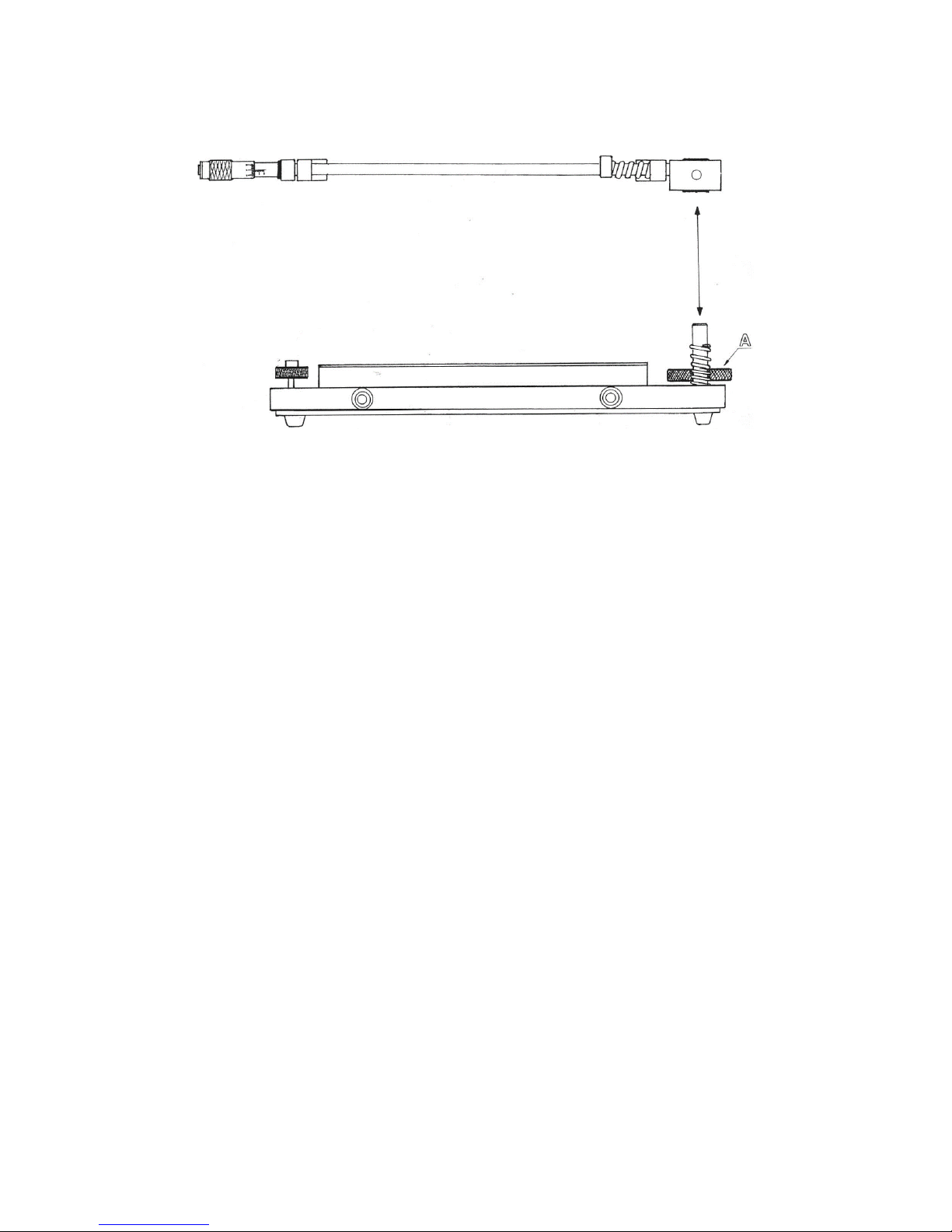
For easy cleaning of the stencil frame turn the top height adjustment knob “A” clockwise until you
can lift the frame from the base plate. After cleaning, replace the frame on the base plate and turn
the knob “A” counter clockwise to secure it.
Product specifications
Dimensions 240 x 370 x 110 mm
Max. PCB size 180 x 240 mm
Max. Stencil size 190 x 270 mm
Weight max. 7 Kg
Warranty
Like all of our other products the SP912 M1 has a one year warranty against faults in material or
production.
Any defective part under this warranty will be repaired or replaced at our cost. The part in question,
or the whole unit, has to be returned to us, together with a detailed description of the fault.
Transportation and costs are the responsibility of the customer.
Defects due to normal wear, as well as defects due to wrong use or lack of maintenance and care are
not covered under this warranty.
 Loading...