

Page 1
Spicer
®
Drive Axles
P/N: SHAIS183
Wheel Differential Bearing Replacement Process
This procedure should only be followed if a wheel differential bearing cup has been identified as having a cup
that has rotated. It is important that this procedure is followed to insure a proper repair. Refer to Dana Service
Manual AXSM-0056 for any additional carrier set-up information.
Effected Axle Models: D170D/D190D
Parts Needed:
1- 131048 – Threaded bearing cup, plain half – diff. lock
1- 131044 – Threaded bearing cup, flange half
1- 512896 – Forward axle, carrier to housing hardware kit
1- 512897 – Rear-rear axle, carrier to housing hardware kit
1- Loctite 540 ( blue )
1- 513061 – Adjusting tool
Instructions:
Block the front and back of one of the steer axle tires.
1.
2. Drain the axle lubricant into a clean container. This lube will be reused after this repair.
3. Disconnect drive shaft from yoke
4. Disconnect IAD lock out and or wheel differential lock out air lines.
5. Remove axle shaft nuts, washers and the axle shafts.
6. Remove carrier to housing capscrews and discard.
7. Place the carrier assembly in a head stand if available.
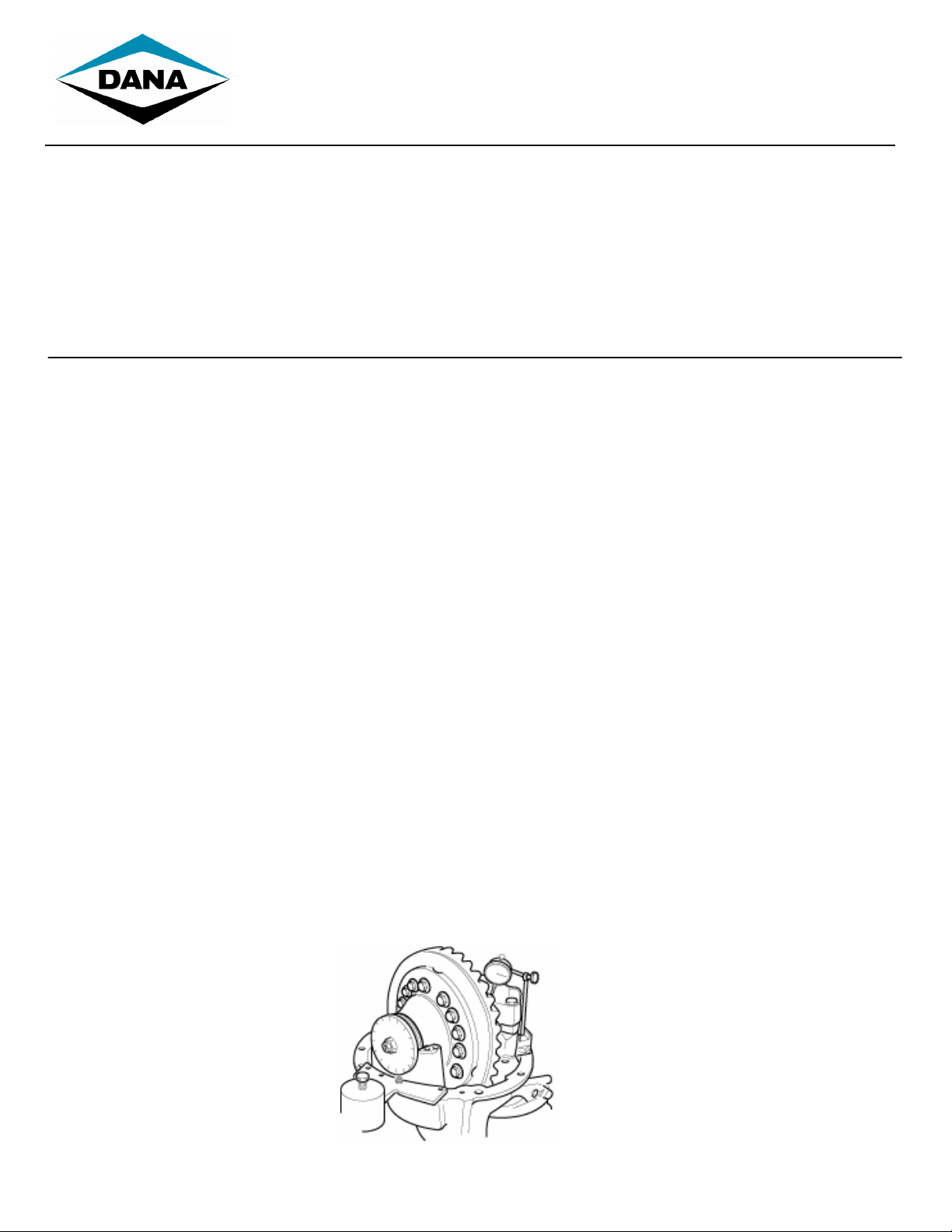
8. Measure and record ring gear backlash. We will be setting the backlash back to this setting during reassembly.
Page 2
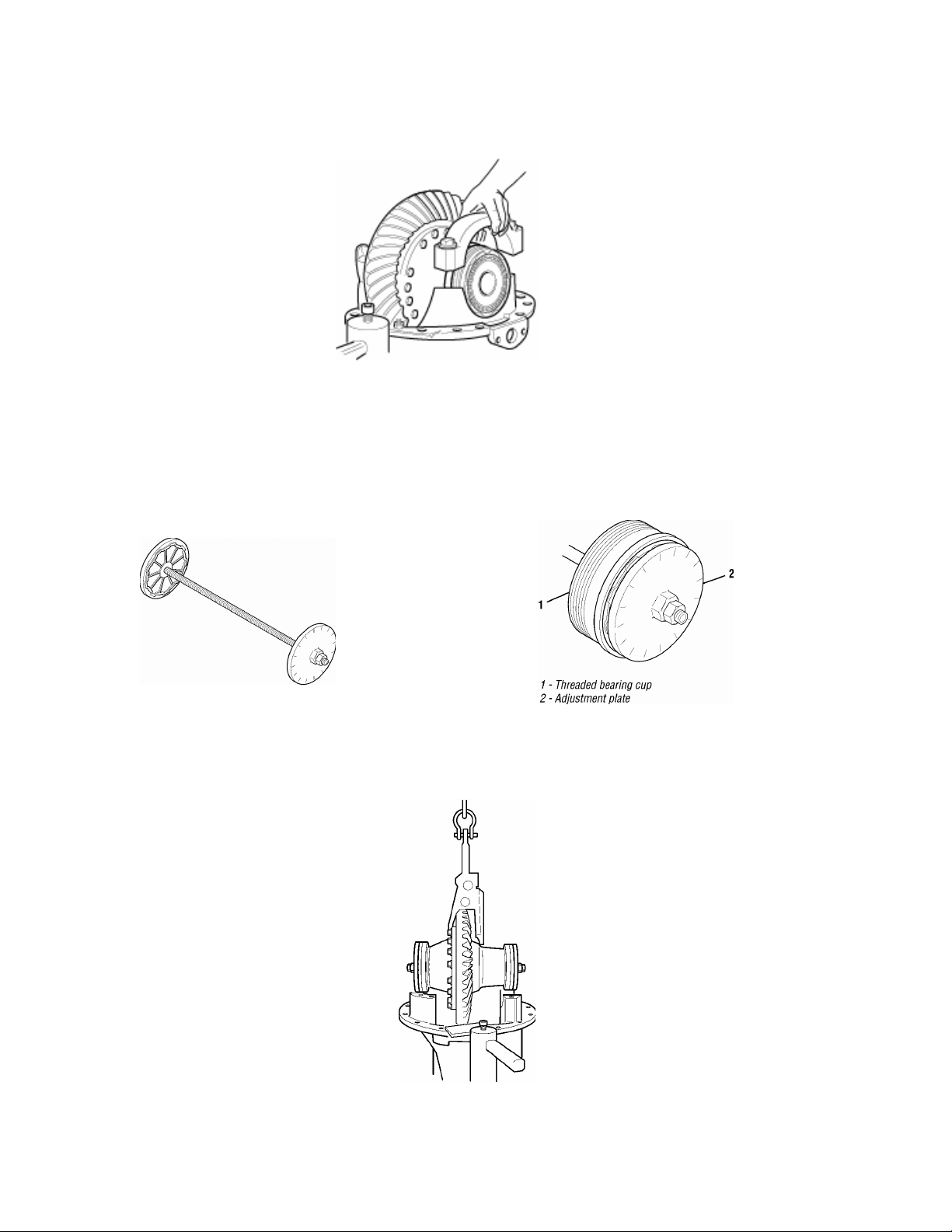
9. Now remove the carrier cap capscrews and carrier caps from the plain half and flange half sides.
10. Using the wheel diff. bearing adjustment tool, remove the wheel diff. assembly from the carrier.
Note: The bearing adjustment tool is made up of a threaded rod, two nuts, two washers and two adjustment plates.
Fit one adjustment plate to the plain half threaded cup. Fit the other adjustment plate to the flange half cup. The
adjustment rings will fit into slots of the threaded bearing cups stamped adjustment ring.
11. Connect the adjuster plates using the threaded rod, washers and nuts. Tighten the nuts on the rod to hold the
threaded cups in place. Carefully raise the hoist to remove the wheel differential and ring gear assembly from the
carrier.
Page 3
12. Use a rag and solvent to clean the threads of the carrier cap and carrier bore. Also clean the threads of the flange
half side threaded adjuster. The plain half side threaded adjuster will be replaced with new, discard old part.
13. Remove the bearing adjustment tool and replace the threaded cup assembly on the plain half side only.
14. Now reassemble the adjustment tool to hold the threaded bearing adjuster in place so the differential assembly
can be reinstalled into the carrier housing.
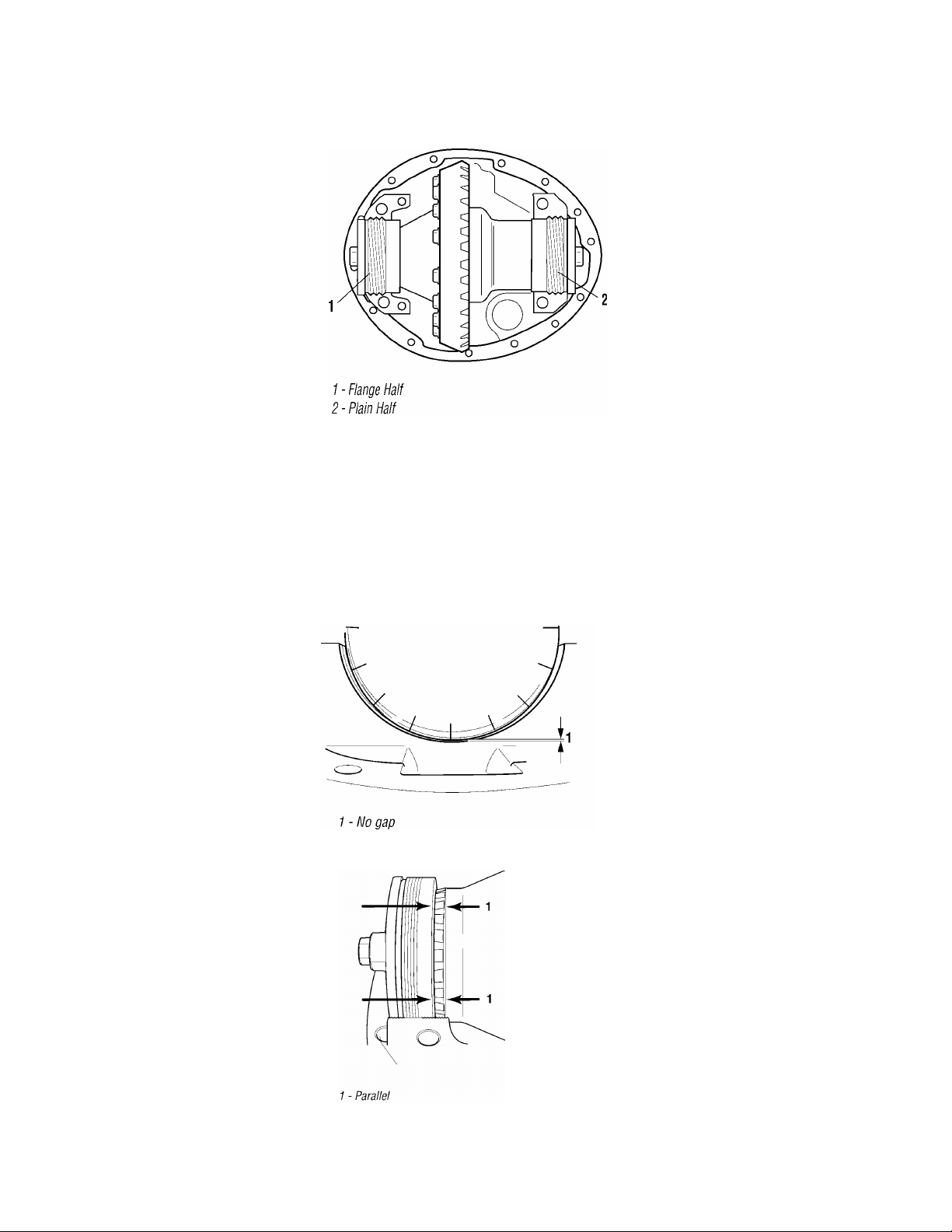
Note: There are two ways to make sure that the threaded cups are seated properly. If there is a misalignment,
reinstall the differential assembly at a slightly different angle.
15. Make sure there is no gap between the carrier threads and the cup threads.
16. Make sure that the bearings cage is parallel to the edge of the threaded cup.
Page 4

17. Use a ratchet or breaker bar and a 1 ¼” deep wall socket to turn the flange half threaded bearing cup in until the
ring gear contacts the pinion (zero backlash). Back the cup out two notches of the adjustment plate.
18. Turn the plain half adjuster ring until there is zero preload on the bearings. This is done by turning the adjuster
plate clockwise until you feel the threaded cup gain resistance. The threaded bearing cup should only be slightly
snugged to achieve a zero preload condition.
19. Obtain two notches of preload by tightening the plain half adjustment plate two notches. Start with the notch at the
top, count two notches counter-clockwise on the adjuster plate. Turn the adjuster plate so that the notch is facing
straight up.
Page 5

1/8” Bead Center
20. Use a rubber mallet to fully seat the threaded bearing cups.
21. With a dial indicator, check the ring and pinion backlash. Set the backlash back to the setting that you recordedat
the beginning of this procedure.
22. Remover the adjuster plates and threaded rod assembly.
23. Next, apply the Loctite 540 (blue) locking compound to both threaded bearing adjusters. Two 1/8” beads should
be applied to the center of the threaded area of the adjuster. Start and end the bead 1” from the carrier housing
surface.
Important Note: It is important that the locking compound does not come in contact with the rollers and/or bearing
race. Compound on bearing surfaces could cause premature bearing failures.
of Threaded Area
1” Space
Page 6

Stake At Both
24. Install the carrier differential bearing caps and capscrews. Make curtain there is no gap between the carrier cap
and the carrier surface.
25. Use an impact gun to securely fasten down the (6) carrier cap fasteners.
Note: Do not completely torque them down at this point.
26. Recheck the backlash. It should be within .001” to .002” from the original setting.
ote: If you have too much backlash, move the ring gear closer to the pinion. Count the number of notches you
N
back off the plain half threaded cup. Each notch equals about 0.003" (0.08 mm) of backlash.
IMPORTANT: In order to maintain the differential bearing preload, you will need to turn the flange half threaded
cup the same amount in the same direction. If you need more backlash, reverse the procedure.
27. Torque the carrier cap fasteners to 340 – 380 N.m (250 – 280 ft. lbs.)
28. Now with a round head punch, stake the outer edge of the retaining ring into the machined slots on each side of
the wheel differential bore.
Location
Page 7

Machined
Ring
29. It is important that the stake depth is deep enough to enter the machined slot in the carrier housing. There will be
a 1/6” space between the adjuster ring and carrier housing on the plain half side. You will see some bending of
the retaining ring.
1/6” Gap
Slot
Deflection
30. The carrier assembly can now be reinstalled into the drive axle housing.
Note: Before installing new fastener hardware or the carrier assembly, inspect the axle housing visually for
cracks, nicks or burrs on all machined surfaces. It is important that all surfaces are cleaned properly. Stud
should only to be replaced if the stud came out with the nut at the time of disassembly.
31. Use a wire wheel to remove any paint, old sealant or oil from the housing and carrier mounting surfaces. Wipe
surfaces down with cleaning solvent to remove any residual oil or dirt.
32. Apply a 1/8” bead of Loctite 5699 Ultra Grey or Dow Corning 3-0100 Automotive Sealant to the housing surface,
it’s important to apply the sealant around (make a loop) all of the threaded bolt holes.
Important Note : Do not spread or smooth-out RTV once applied. RTV will set in 20 Minutes. Install carrier
before RTV sets or reapply.
33. Install carrier into housing.
34. Install new fasteners and run them down with an impact gun in a crisscross pattern.
Page 8

35. Torque carrier to housing capscrews to the chart below.
Axle Location Dana Kit Part Number Fastener Type N.m Ibs-ft
Forward 512896 Capscrew and Nut 338 - 393 250 - 290
Rear - Rear 512897 Capscrew and Nut 338 - 393 250 - 290
36. Clean axle shaft flanges and wheel hub surfaces and install new axle shaft gasket.
37. Reinstall the axle shaft, washers and nuts, torque to spec.
38. Reco
nnect IAD shift cylinder and/or wheel diff. lock air line.
39. Reinstall the driveline.
40. Remove fill plug from housing cover and refill the housing using the same lubricant that was removed. If needed,
add lube and fill until level with the bottom of the fill hole.
pec’ing or service assistance, call 1-800-
For s
24 ho
rs a day, 7 days a week.
u
Or visit our web site at: http://www.VSLFHUSDUWV.com
SHAIS183A Copyright Dana Corporation, 2008 Heavy Vehicle Technologies and Systems Service
June 2008 All Rights Reserved. P.O. Box
Printed in U.S.A. www.d
ana.com
Dana Corporation
Toledo, Ohio 43697-0321
 Loading...