

Page 1
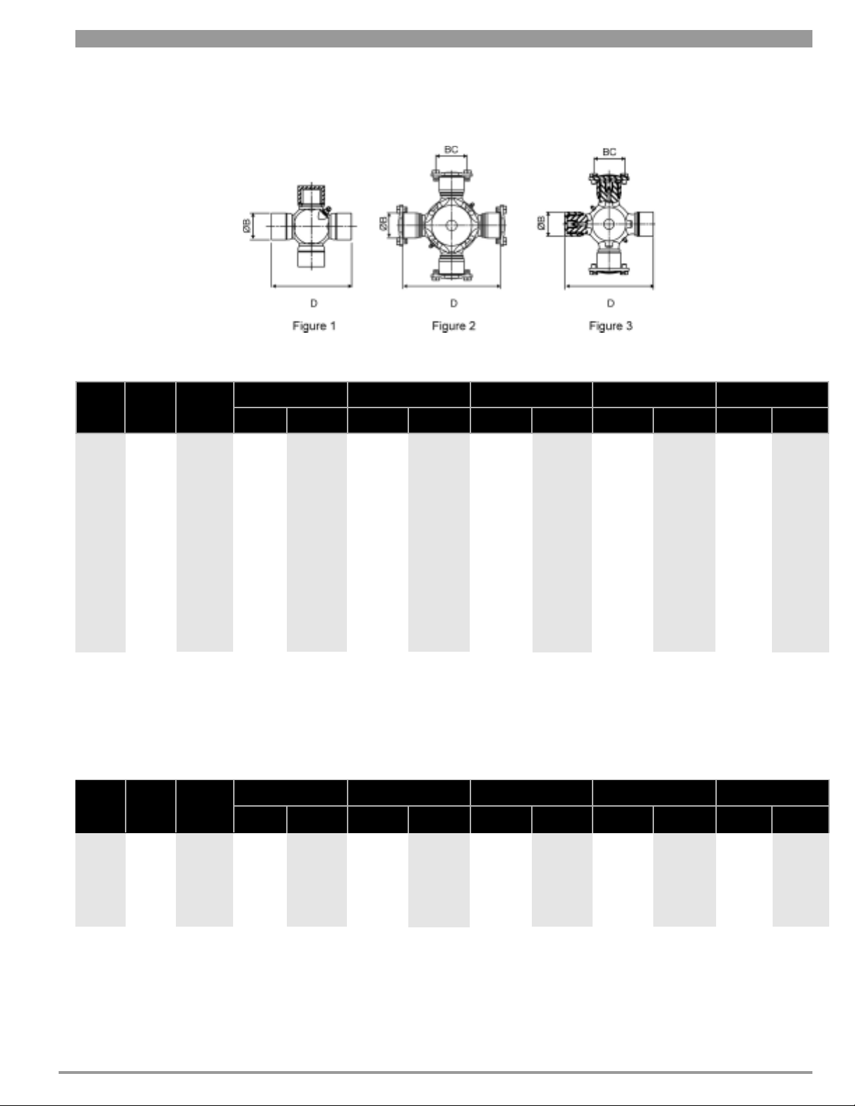
Universal Joint Kits
ø B (Bearing Diameter)
D (Overall Span)
BC (Bolt Hole Centers)
Cross Length
nal Cross Trunnion
Jour
Diameter
Figure
Series Part Number
1
1
1
1
2
2
2
2
2
1310
1410
1480
1550
1610
1710
1760
1810
1880
5-153X
5-160X
5-263X
5-275X
5-279X
5-280X
5-407X
5-281X
5-380X
Inches Millimeters
1.06
1.18
1.37
1.37
1.88
1.94
1.94
1.94
2.18
26.9
29.9
34.8
34.8
47.7
49.3
49.3
49.3
55.4
Inches Millimeters Inches Millimeters Inches Millimeters
3.22
4.18
4.18
4.96
5.31
6.09
6.99
7.55
8.09
81.8
106.2
106.2
126.0
134.9
154.7
177.5
191.8
205.5
-
-
-
-
2.31
2.43
2.43
2.43
2.81
Universal Joint Kits for Half Round End Yokes
Figure
3
Series Part Number
1610
5-674X
ø B (Bearing Diameter)
Inches Millimeters
1.88
47.8
D (Overall Span)
Inches Millimeters Inches Millimeters Inches Millimeters
5.31
134.9
BC (Bolt Hole Centers) Cross Length
2.31
58.7
61.7
61.7
61.7
71.4
58.7
Inches
-
-
-
-
2.96
3.93
3.87
4.65
4.99
5.77
6.68
7.25
7.59
4.99
75.2
99.8
98.3
118.1
126.7
146.6
169.7
184.2
192.8
126.7
0.65
0.76
0.88
0.88
1.26
1.26
1.26
1.26
1.37
Journal Cross Trunnion
Inches Millimeters
1.26
Millimeters
16.5
19.3
22.4
22.4
32.0
32.0
32.0
32.0
34.8
Diameter
32.0
3
3
3
© 2005 Dana Corporation
1710
1760
1810
5-442X
5-677X
5-6-768X
1.94
1.94
1.94
49.3
49.3
49.3
6.09
6.99
7.55
154.7
177.5
191.8
1
2.43
2.43
2.43
61.7
61.7
61.7
5.77
6.68
7.25
146.6
169.7
184.2
1.26
1.26
1.26
Dimension Detail
32.0
32.0
32.0
Page 2
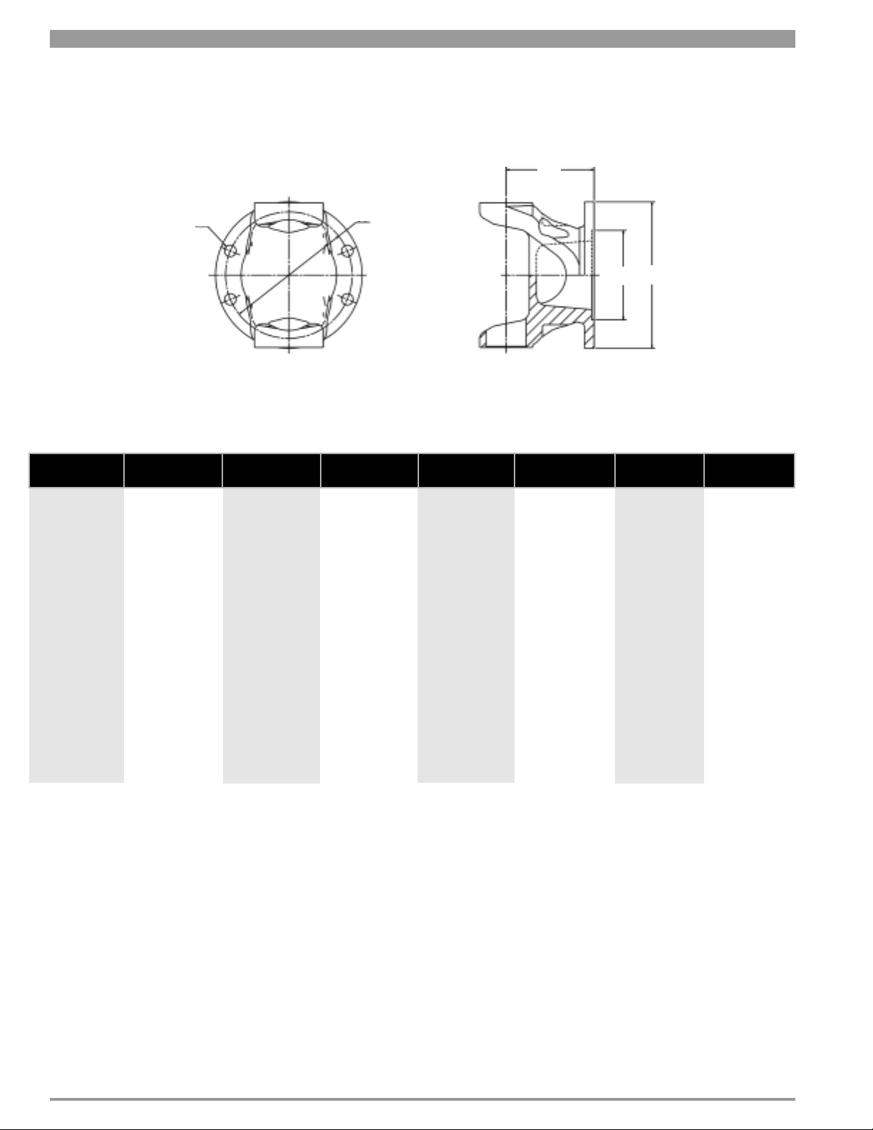
DIN Pattern Flange Yokes
M
øD
No. of HolesPart NumberSeries
1310
1410
1480
1550 4-2-1069 8 150.0 130.0 90.0 80.0 M12
1610 5-2-1149 8 150.0 130.0 90.0 91.9 M12
1710
1760
1760
ements in Millimeters
All Measur
2-2-1329
2-2-1339
3-2-1239
3-2-1159
3-2-1299
02-323
3-2-1219
6-2-1259
6-2-1309
6-2-1339
6.3-2-89
6.3-2-69
6.3-2-59
6.3-2-89
6.3-2-69
6.3-2-59
4
6
6
8
8
6
8
8
8
8
8
8
10
8
8
10
øB/PCD
ød
90.0
100.0
100.0
120.0
120.0
120.0
120.0
165.0
180.0
180.0
180.0
180.0
180.0
180.0
180.0
180.0
Pitch Cir
øB/PCD
cle Diameter
74.5
84.0
84.0
101.5
101.5
101.5
101.5
140.0
155.5
155.5
155.5
155.5
155.5
155.5
155.5
155.5
ø C
47.0
57.0
57.0
75.0
75.0
82.5
82.5
95.0
110.0
110.0
110.0
110.0
110.0
110.0
110.0
110.0
ød
ø C
M - Flange Face
to Centerline FF-
50
50
64.3
64.3
60.0
60.0
60.0
101.6
101.6
101.6
108.0
108.0
108.0
108.0
108.0
108.0
C
øD
Thru Hole Diameter
L
M8
M8
M8
M10
M10
M10
M10
M16
M14
M16
M14
M16
M16
M14
M16
M16
© 2005 Dana Corporation
2
Dimension Detail
Page 3
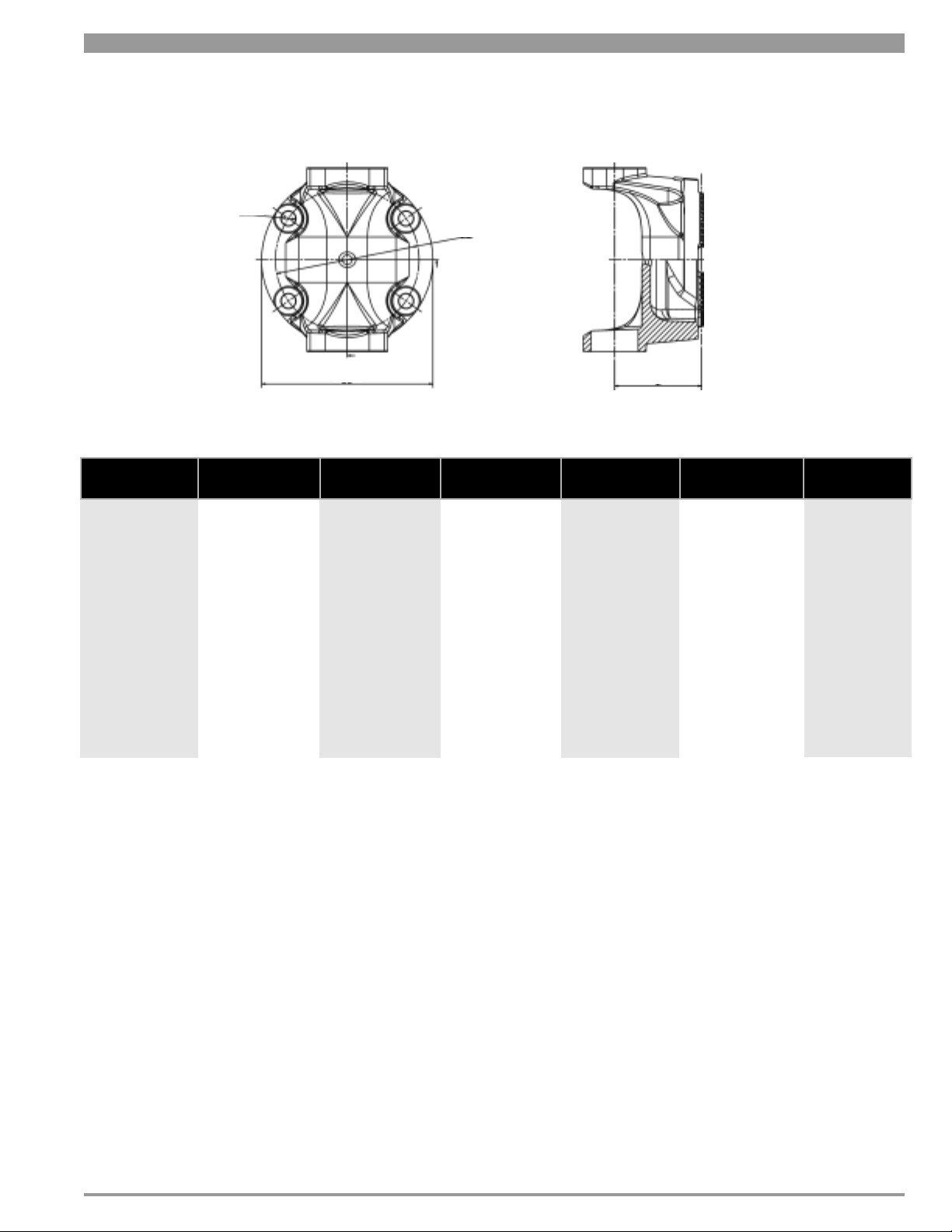
T-Type Flanges
øD
øB/PCD
ød
PatternPart NumberSeries
1310
1410 3-2-25 T120 120.0 100.0 57.0 M11
1480 3-2-15 T120 120.0 100.0 60.0 M11
1550
1610
1710
1760 6.3-2-15 T180 180.0 180.0 88.0 M15
1550
1880
All Measurements in Millimeters
4-2-35
4-2-25
6-2-15
6-2-25
6.5-2-15
T120
T150
T150
T180
T180 180.0
ød
120.0
150.0
150.0
180.0
øB/PCD
Pitch Circle Diameter
100.0
130.0
130.0
150.0
150.0
M
M - Flange Face
to Centerline FF
-
65.0
68.0
81.0
83.0
88.0 M15
C
L
u Hole Diameter
Thr
M11
M13
M13
M15
øD
© 2005 Dana Corporation
3
Dimension Detail
Page 4

Flange Yokes
Series
1310
1350
øD
Part Number
2-2-329
3-2-119
3-2-159
3-2-309
øB/PCD
E
Distance
Across
Lugs
3.47"
(88.14 mm)
3.88"
(98.55 mm)
4.44"
(112.78 mm)
øA
Bearing
Diameter
1.06"
(26.92 mm)
1.19"
(30.24 mm)
1.19"
(30.24 mm)
M
M
øD
øB/PCD
E
øC
E
øC
øA
øA
E Bolt Detail C M ß
Flange
Swing
Diameter
3.88"
(98.55 mm)
4.62"
(117.35 mm)
4.96"
(125.98 mm)
øB/PCD
(pitch circle
diameter)
3.12"
(79.25 mm)
3.75"
(95.25 mm)
3.75"
(95.25 mm)
øD
Thru Hole
Diameter
.38"
.44"
.44"
Size Number of
3/8 - 24
7/16 - 20
7/16 - 20
Holes
4
4
4
Torque Pilot Diameter
22-26 Lb. Ft.
(29.8-35.25 Nm)
63-75 Lb. Ft.
(85.41-101.68 Nm)
63-75 Lb. Ft.
(85.41-101.68 Nm)
M - Male F - Female
M-2.38"
(M-60.45 mm)
M-2.75"
(M-69.85 mm)
M-2.75"
(M-69.85 mm)
Flange Face
to Centerline
(35.05 mm)
1.56"
(39.62 mm)
1.69"
(42.93 mm)
1.38"
Joint
Angle
20˚
20˚
22˚
(4)
1410
14801550
Note: Spicer Flanges Bolts are Special Heat Treated Grade 8 Bolts. Do Not Substitute Inferior Grade Bolts.
(1)
Bearing plate scr
(2)
For AC tr
(3)
For Bendix brake
(4)
Angles shown are the maximum for momentary operation
Example: 22˚/29˚ 22˚ angle when mated with long lug yokes, 29˚ angle when mated short lug yokes
3-2-309
3-2-939
3-2-429
3-2-479
3-2-489
4-2-669
4-2-1159
(3)
3-2-699
ew holes located on centerline of yoke
u-stop brake
4.44"
(112.78 mm)
4.44"
(112.78 mm)
4.44"
(112.78 mm)
5.25"
(133.35 mm)
5.25"
(133.35 mm)
5.25"
(133.35 mm)
1.19"
(30.23 mm)
1.38"
(35.05 mm)
1.38"
(35.05 mm)
1.38"
(35.05 mm)
1.38"
(35.05 mm)
1.38"
(35.05 mm)
5.88"
(149.35 mm)
5.88"
(149.35 mm)
5.88"
(149.35 mm)
5.88"
(149.35 mm)
5.88"
(149.35 mm)
6.88"
(174.75 mm)
4.75"
(120.65)
4.75"
(120.65 mm)
4.75"
(120.65 mm)
4.75"
(120.65 mm)
4.75"
(120.65 mm)
6.12"
(155.45 mm)
.50"
.50"
.50"
.50"
.50"
.38"
1/2 - 20
1/2 - 20
1/2 - 20
1/2 - 20
1/2 - 20
3/8 - 24
4
4
4
4
4
8
97-116 Lb. Ft.
(85.41-101.68 Nm)
97-116 Lb. Ft.
(131.51-157.27 Nm)
97-116 Lb. Ft.
(131.51-157.27 Nm)
97-116 Lb. Ft.
(131.51-157.27 Nm)
97-116 Lb. Ft.
(131.51-157.27 Nm)
22-26 Lb. Ft.
(29.8-35.25 Nm)
M-3.75"
(M-95.25 mm)
M-3.75"
(M-95.25 mm)
M-3.75"
(M-95.25 mm)
M-3.75"
(M-95.25 mm)
M-3.75"
(M-95.25 mm)
M-5.31"
(M-134.87 mm)
2.00"
(50.80 mm)
2.00"
(50.80 mm)
1.50"
(38.10 mm)
2.00"
(50.80 mm)
1.50"
(38.10 mm)
2.00"
(50.80 mm)
30˚
20˚
8˚
22˚
8˚
-
© 2005 Dana Corporation
4
Dimension Detail
Page 5

Flange Yokes cont.
Series
øD
161017101810
Part Number
5-2-599
5-2-619
5-2-629
5-2-709
5-2-279
M
M
øD
øB/PCD
E
øC
øB/PCD
E
øC
øA
øA
E
Distance
Across
Lugs
3.31"
(84.07 mm)
(1)
5.31"
(134.87 mm)
øA
Bearing
Diameter
1.88"
47.75 mm
1.88"
47.74 mm
E Bolt Detail C M ß
Flange
Swing
Diameter
6.88"
(174.75 mm)
6.88"
(174.75 mm)
øB/PCD
cle
(pitch cir
diameter)
6.12"
(155.45 mm)
6.12"
(155.45 mm)
øD
Thru Hole
Diameter
.38"
.38"
Size
3/8 - 24
3/8 - 24
Number of
Holes
8
8
T
orque Pilot Diameter
22-26 Lb. Ft.
(29.8-35.25 Nm)
22-26 Lb. Ft.
(29.8-35.25 Nm)
M - Male F - Female
(M-168.15mm F-134.87)
M-6.62" F-5.31"
M-6.62"
(M-168.15 mm)
(2)
Flange Face
to Centerline
2.75"
(69.85 mm)
2.75"
(69.85 mm)
Joint
Angle
22˚
20˚
20˚
20˚
22˚
(4)
5-2-379
6-2-749
6-2-739
6.5-2-329
8-2-109
1880
Note: Spicer Flanges Bolts are Special Heat Treated Grade 8 Bolts. Do Not Substitute Inferior Grade Bolts.
(1)
Bearing plate screw holes located on centerline of yoke
(2)
For AC tr
(3)
For Bendix brake
(4)
Angles shown are the maximum for momentar
Example: 22˚/29˚ 22˚ angle when mated with long lug yokes, 29˚ angle when mated short lug yokes
8-2-119
u-stop brake
5.31"
(134.87 mm)
6.09"
(157.69 mm)
7.55"
(191.77 mm)
8.09"
(205.49 mm)
8.09"
(205.49 mm)
y operation
1.88"
47.75 mm
1.94"
49.28 mm
1.94"
49.28 mm
2.18"
55.37 mm
2.18"
55.37 mm
6.88"
(174.75 mm)
8.00"
(203.20 mm)
8.00"
(203.20 mm)
9.75"
(247.65 mm)
9.75"
(247.65 mm)
6.12"
(155.45 mm)
7.25"
(184.15 mm)
7.25"
(184.15 mm)
8.25"
(209.55 mm)
8.25"
(209.55 mm)
.38"
.38"
.44"
.62"
.62"
3/8 - 24
3/8 - 24
7/16 - 20
5/8 - 18
5/8 - 18
8
8
12
8
8
22-26 Lb. Ft.
(29.8-35.25 Nm)
22-26 Lb. Ft.
(29.8-35.25 Nm)
63-75 Lb. Ft.
(85.41-101.68 Nm)
194-232 Lb. Ft.
(263.02-314.55 Nm)
194-232 Lb. Ft.
(263.02-314.55 Nm)
M-6.62"
(M-168.15 mm)
M-6.62"
(M-168.15 mm)
M-7.75"
(M-196.85 mm)
M-7.00"
(M-177.80 mm)
M-7.00"
(M-177.80 mm)
1.88"
(47.75 mm)
3.00"
(76.20 mm)
3.38"
(85.85 mm)
3.50"
(88.90 mm)
2.50"
(63.50 mm)
8˚
22˚/29˚
30˚
22˚
8˚
© 2005 Dana Corporation
5
Dimension Detail
Page 6

10 Series and Spicer Life Series
Application Form for Heavy/Medium Duty Applications
Company:
E-Mail:
Phone:
Vocation:
Vehicle Make:
Weight - Empty:
*GVW (front):
Tire - Size:
Engine - Make:
*Net Torque:
Gross Torque:
*GVW (rear):
Make:
Model:
At Speed:
At Speed:
Maximum Operating Speed (including engine over speed):
Trans - Make:
*Ratios - Forward (including overdrive):
Contact:
Date:
Fax:
GVW Total:
Net H.P.:
Gross H.P.:
Model:
*Reverse:
Vehicle Model:
GCW:
*Rolling Radius:
Displacement:
At Speed:
At Speed:
Torque Converter - Make:
Auxiliary - Make:
Transfer Case - Make:
Torque Split Ratio - Front:
Axle - Make Front:
Axle - Make Rear:
B
Life Expectancy:
10
ehicle Duty Cycle:
V
Description of Vehicle Function:
Model:
Model:
Model:
Model:
Model:
*Stall Ratio:
Ratios:
Ratios:
Rear:
*Ratios:
*Ratios:
Fax:
Signed:
Title:
Spicer Engineer:
E-Mail:
*Required Fields
© 2005 Dana Corporation
1
Phone:
Fax:
Application Forms
Page 7

10 Series and Spicer Life Series
Application Form for Heavy/Medium Duty Applications
Vehicle Position
Trans. to Rear Axle
Trans. to Auxiliary
Auxiliary to Rear Axle
Trans. to Mid Bearing
Mid Bearing to Rear Axle
Interaxle
Wheel Drive
Series Dana Part Number
*Wheel Drive Vehicle Application Sketch
Plan View
Side View
Proposed By:
Signed:
Title:
*Required Fields
© 2005 Dana Corporation
2
Application Forms
Page 8

© 2005 Dana Corporation
Application F
ms
or
Page 9

© 2005 Dana Corporation
Application Forms
 Loading...