

Page 1
Spicer® Tandem Drive Axles
Service Manual
Spicer® Tandem Drive Axles
AXSM-0045
September 2007
Page 2
Spicer Axle Service and Maintenance Instructions
Tandem Drive Axles
Dual Range and Planetary Double Reduction Gearing
Introduction
Dana Corporation, Axle & Brake Division, presents this
publication to aid in maintenance and overhaul of Spicer
tandem drive axles.
Service and Maintenance instructions cover Spicer Dual
Range (2-Speed) and Planetary Double Reduction Tandem
Axles. Instructions are applicable to both gearing types
unless specified otherwise.
Five basic axle series are included in this book. Their design
is common with differences in load capacity and two gearing
types.
Load
Capacity
(lbs.)
Dual Range
34,000 DT340, DT341
38,000
38,000
40,000
40,000
45,000
DT380(P)
* DT381(P)
DT400-P, DT401-P
DT402(P)
DT451 -P
The suffix letter “P” in the Model No. indicates the axle
is equipped with a gear-driven Lube Pump, designed to
provide additional lubrication to the inter-axle differential
and related parts.
Instructions contained herein are applicable to all axle models
unless specified otherwise.
For brake information and axle mounting suspension
systems, refer to pertinent truck manufacturer’s literature.
Model Numbers
DP381(P)
Planetary
Double Reduction
DP340, DP341
DP380(P)
DP400-P, DP401 -P
DP402(P)
DP451-P
Typical 3PICER Tandem Drive
Axle (Dual Range illustrated).
Design Variations:
Two design variations of tandem
axles are included in this manual.
The major difference is in the shaft
sp line design. Refer to page 5 for
deails.
*NOTE: DS381 (P) axles manufactured
after April 1985 are rated at 40,000 lbs,
,
Contents
Description and Operation
Gearing and Torque Distribution
Lubrication
Cleaning, Inspection, Replacement
Adjustments
• Wheel Bearings
•Adjust Input Shaft End Play
•Pinion Bearing Preload
•Differential Bearing Preload and
Ring Gear Backlash Adjustment
Ring Gear and Pinion Tooth Contact
Fastener Tightening Specifications
Rear Axle Differential
Carrier Replacement
Forward Axle Differential
Carrier Replacement
Power Divider Replacement
Power Divider Overhaul
•Remove Power Divider
from Differential Carrier
•Disassemble power Divider Cover
•Disassemble Inter-axle Differential
*Service Bulletin Supplement
(Checking Input Shaft End Play —
●
Disassemble Output Shaft
●
Assemble Output Shaft
●
Assemble Inter-axle Differential
●
Assemble Power Divider Cover
●
Install Power Divider on Diff. Carrier
●
Adjust Input Shaft End Play
Differential Carrier Overhaul
●
Disassemble Differential Carrier
●
Disassemble Drive Pinion
•
Disassemble Wheel Differential
●
Assemble Wheel Differential
●
Assemble Drive Pinion
●
Forward Axle- Install Pinion
●
Forward Axle - Install Helical Gear
●
Forward Axle - Install Differential
Assembly in Carrier
●
Rear Axle - Install Pinion and
Differential in Carrier
Misc. Torque Fastening Chart
DuaI Range Axle Shift System
Axle Models with Thrust Button
2
Price $3.50
Page 3
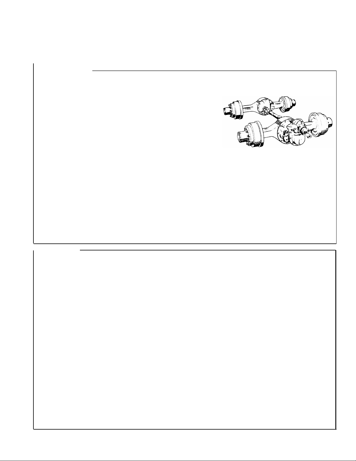
Axle and Carrier Assembly Model Identification
Spicer Axle
Spicer Axle
Spicer
Spicer Axle
Spicer Axle
Spicer
Axle Specification Number
I
The complete axle is identified by the specification
number stamped on the rear right-hand side of the
axle. housing. This number identifies all component
parts of the axle as built by Spicer, including special
OEM requirements such as yoke or flange.
In addition, some axles
may include a metal
identification tag (see
illustration).
Metal Identification Tag
Ring Gear and Pinion Identification
Ring Gear and Drive Pinion
are matched parts and must
be replaced in sets. Check the
appropriate Spicer Axle parts book
for part numbers and ordering
instructions.
To aid in identifying gear sets, both
parts are stamped with such infor-
mation as number of pinion and
ring gear teeth, individual part
number and matched set number
(refer to adjacent drawing).
3
Page 4
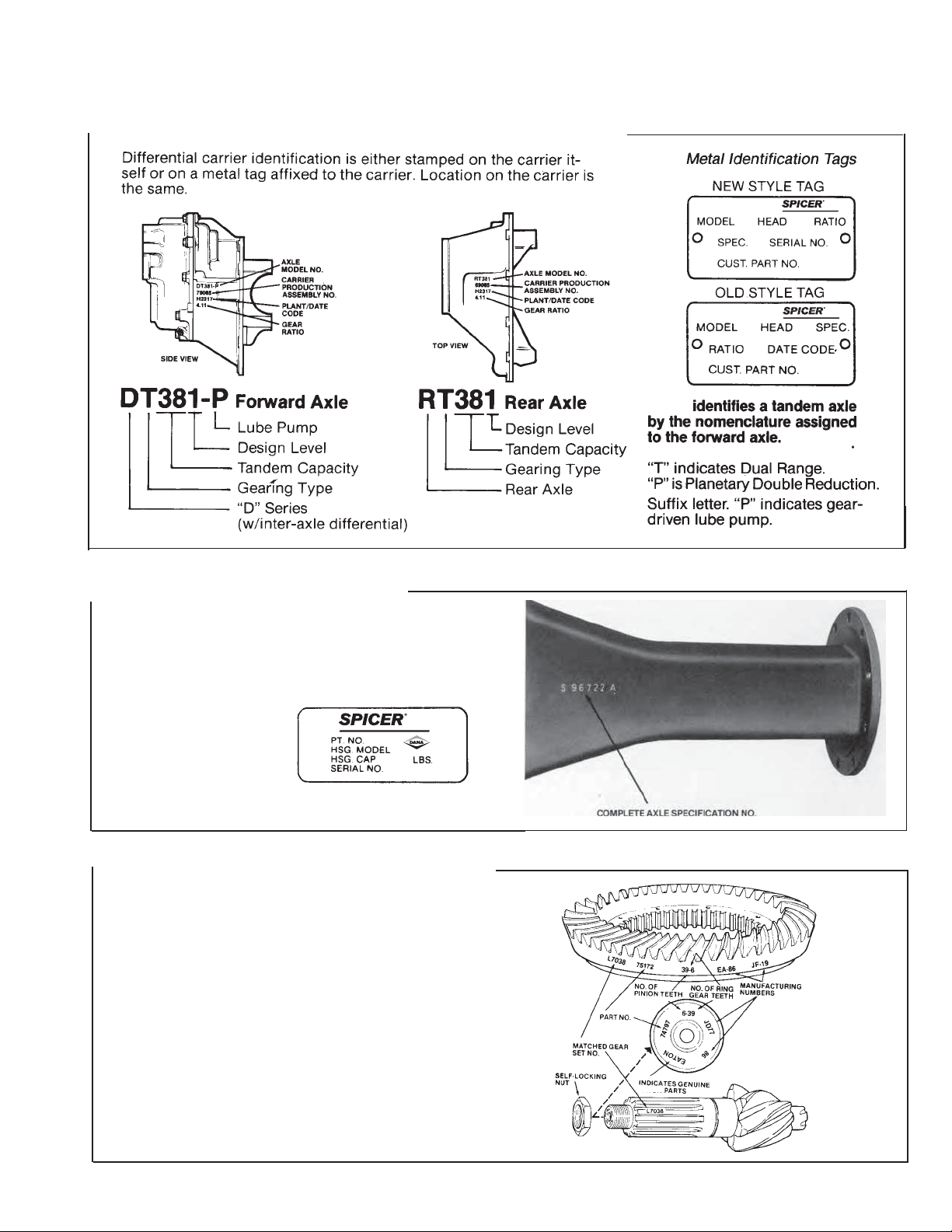
Spicer¬Dual Range Tandem Drive Axles
Description and Operation
Spicer Dual Range Tandems are
basically 2-Speed, shiftable drive
axles. They provide two gearing
ratios (low and high ranges) and
are designed for heavy-duty service
in on-off highway operations. Low
range for deep gear reduction and
slow speed hauling off highway.
High range for cruising speeds on
highway.
The complete tandem axle
assembly includes two axle units,
each with double gear reduction
capability coupled by a 2-gear S
power divider.
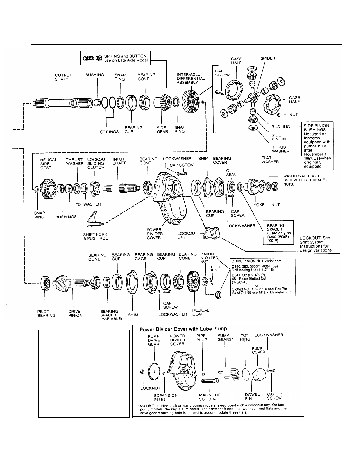
Power Divider
In operation, the power divider accepts the torque from the vehicle
drivelne and distributes it equally to the two axles.
This assembly is of the two-gear design consisting of an input shaft,
inter-axle differential, output shaft and two constant-mesh helical
gears.
The inter-axle differential compensates for axle speed variations in the
same way the wheel differential works between the two wheels of a
single drive axle. This unit also acts as a central point in distribution
of torque to the two axles.
The power divider also includes a driver-controlled, air-operated
lockout. When lockout is engaged, it mechanically prevents inter-axle
differentiation for better performance under poor traction conditions.
Lube Pump
Tandem Axles with suffix letter "P" in Model No. are equipped with a
lube pump to provide positive lubrication to the inter-axle differential
and other power divider parts. This pump is operated by a drive gear
engaged with the input shaft splines. When vehicle is moving in a
forward direction, pressurized lube is delivered to the vital power
divider parts.
PICER Dual Range Gearing
with Lube Pump
Lube Pump System
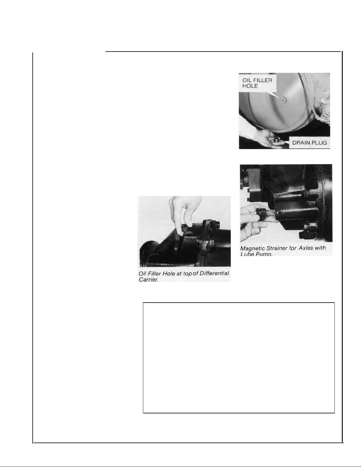
The pump lube system
incorporates a magnetic strainer
screen. To keep the system clean,
the magnet traps minute particles
and the screen blocks out large
particles of foreign material.
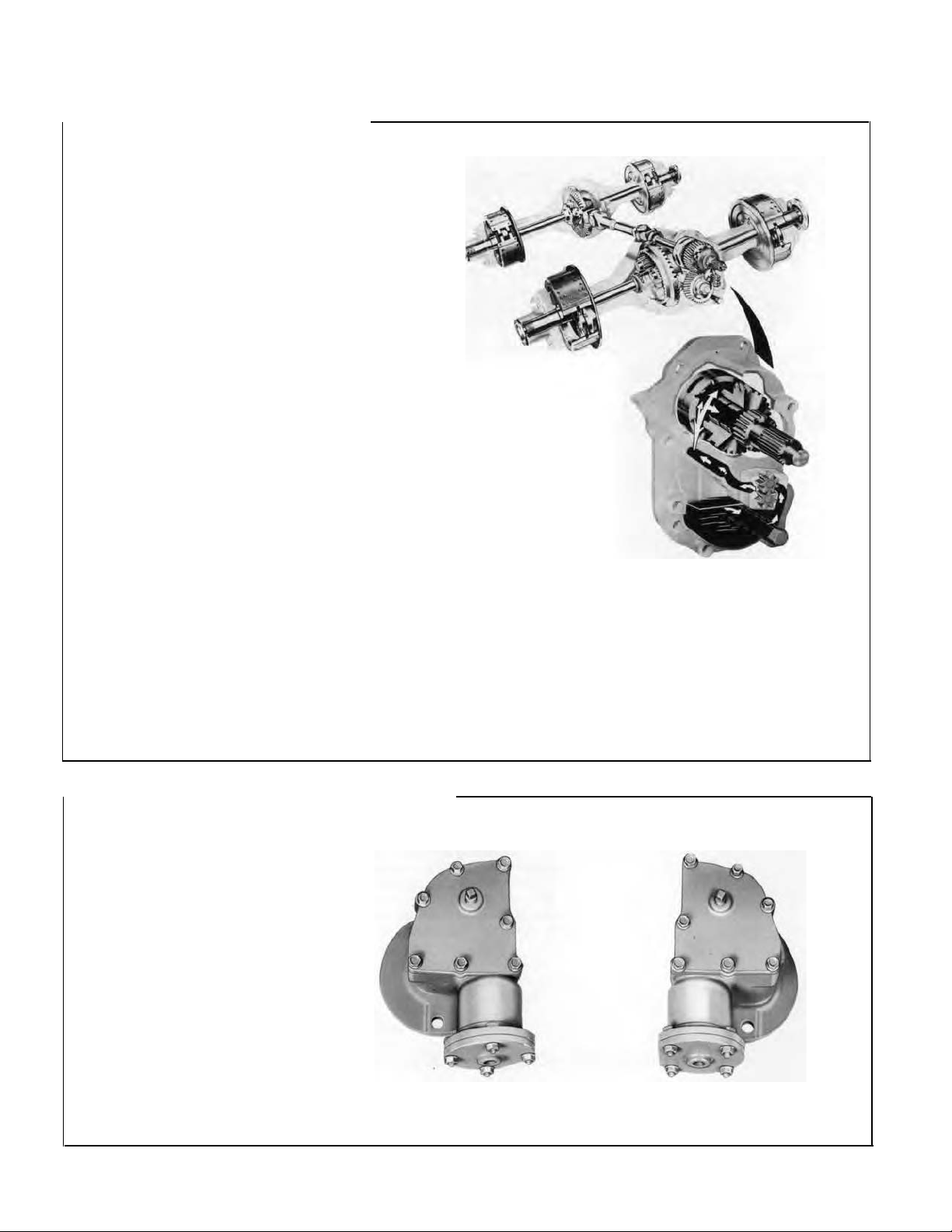
Dual Range Tandem Shift System
Range selection is accomplished
by an air shift system and is drivercontrolled through a cab-mounted
air control valve.
The control valve operates two
shift units (one for each axle)
which mechanically engages or
disengages the planetary gearing.
For operation description, refer
to Shift System section in this
manual.
4
Forward Axle
Shift Unit
Rear Ax/e
Shift Unit
Page 5
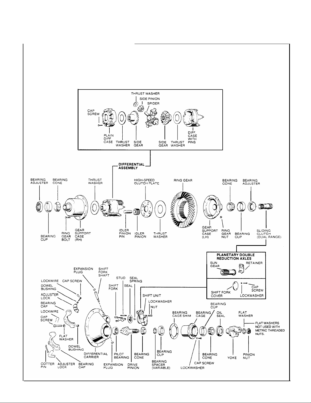
Spicer Planetary Double Reduction Axles
Description and Operation
The Planetary Double Reduction
Tandem Axle shares its basic
design concepts and many
components with the Dual Range
Tandem. The principle variation
is the permanent engagement of
the double reduction feature. A
stationary sun gear, fixed in
engagement with the low-speed
clutch plate, replaces the sliding
clutch gear and provides continuous
double reduction operation in the
same manner as the dual range
axle when in Low Range.
Torque distribution and power flow
is same as Dual Range Gearing in
Low Range (see page 7).
Design Variations (Dual Range and Planetary Double Reduction Axles)
NOTE: To assist in identifying the axle being serviced, here are the
major design variations within the axle series covered by this manual.
D341, 381(P)
401-P, 402(P),
451-P
16
34
44
36
5 pitch
41
39
1-5/8"-18
self-locking or
slotted nut with
roll pin M42 x 1.5
after 7/1 /95
1-1/2"-18
self locking
M36 x 1.5after
7/1/95
Axle Series
Output Shaft Splines
Side Gear End
Output End
Input Shaft Splines
Input End
Diff. End
Helical Gear
Drive Pinion Splines
Forward Axle
Rear Axle
Drive Pinion Nut
Forward Axle
Rear Axle
D340, 380(P)
400-P
16
10
16
36
7 pitch
10
10
1-1/2"-18
self-locking
1-1/2"-18
self-locking
Axle Shaft &
Side Gear Splines
Lube Pump Drive Shaft.
pump models is equipped with a woodruff key. On
late pump models, the key is eliminated. The drive
shaft end has two machined flats and the drive gear
mounting hole is shaped to accommodate these flats.
D340,380(P)-16
D400-P-33
The drive shaft on early
D341-39
D381(P), D402(P) -41
D401-R D451-P -33
5
Page 6
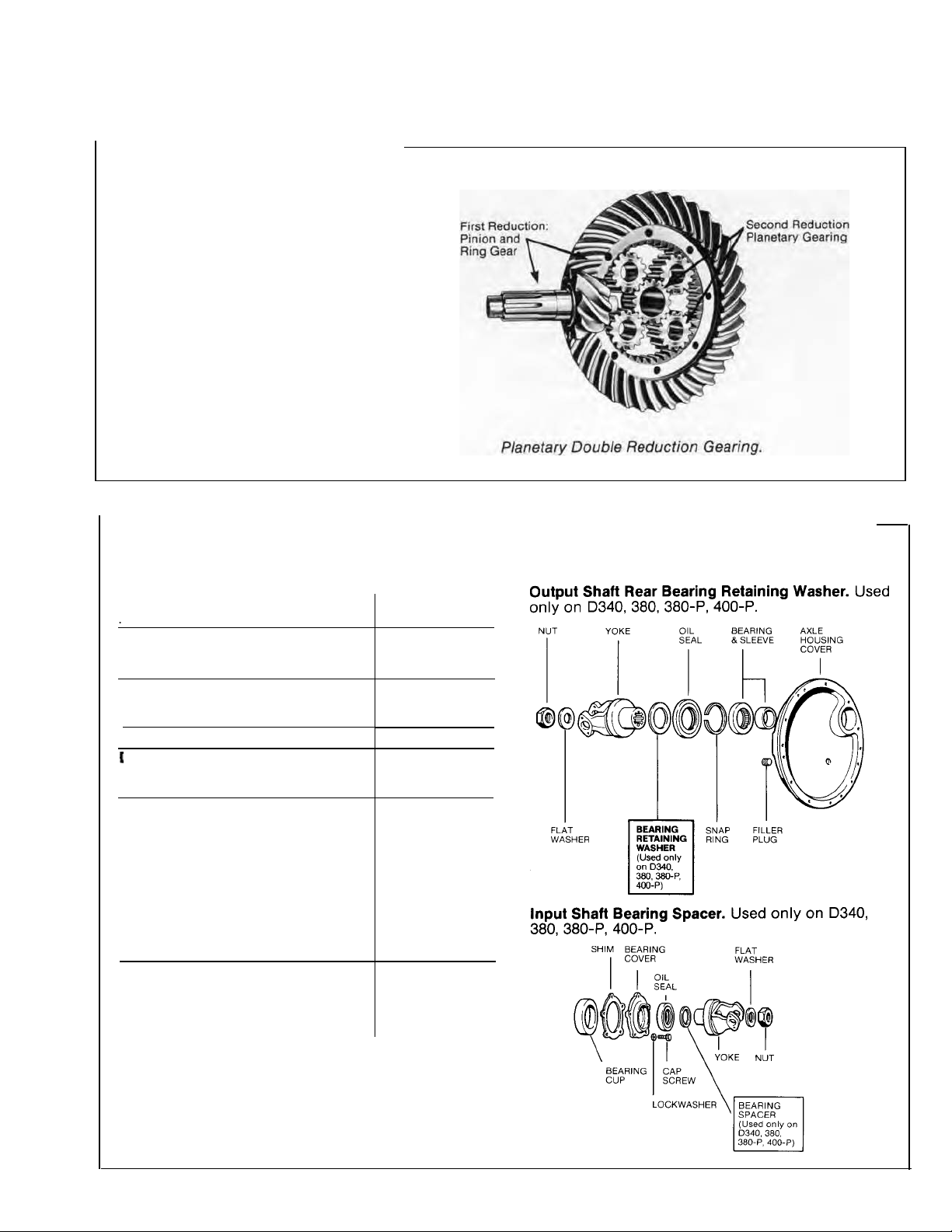
Gearing and Torque Distribution
Dual Range Gearing
The gearing for each axle is a
combination of a spiral bevel ring
gear and pinion and a planetary
unit.
First reduction (High Range) is
provided by the spiral bevel
gearing.
Second reduction (Low Range) is
through the planetary gearing.
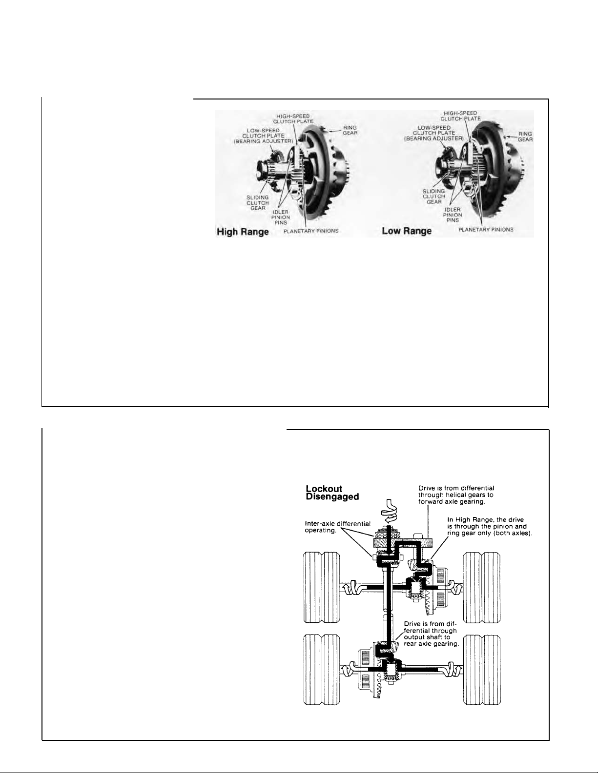
Four planetary idler pinions are
confined within the ring gear and
mesh with the ring gear internal
teeth. The planetary gears rotate
around a sliding clutch gear.
Each axle is equipped with a shift
unit, which operates the sliding
clutch gear to provide means for
selecting the axle range. Range
selection is accomplished through
the movement of the sliding clutch
gear in and out of engagement
with low and high-speed clutch
plates.
The sliding clutch gear is locked
into the high-speed clutch plate
and rotates as part of the differential assembly. The planetary pinions are stationary and the axle
uses only the single reduction of
the ring gear and pinion. Power
flow is through the drive pinion,
ring gear, differential unit and axle
shafts.
The sliding clutch gear is shifted
into engagement with the lowspeed clutch plate (an integral
part of the bearing adjuster). The
sliding clutch is held stationary and
the planetary pinions are forced to
rotate around it. Power flow is now
through drive pinion, ring gear,
planetary gearing, differential unit
and axle shafts. The axle uses two
reductions to multiply torque. The
planetary unit adds approximately
36¡/0 more reduction to the primary
gear set. Torque is multiplied on
an equivalent basis.
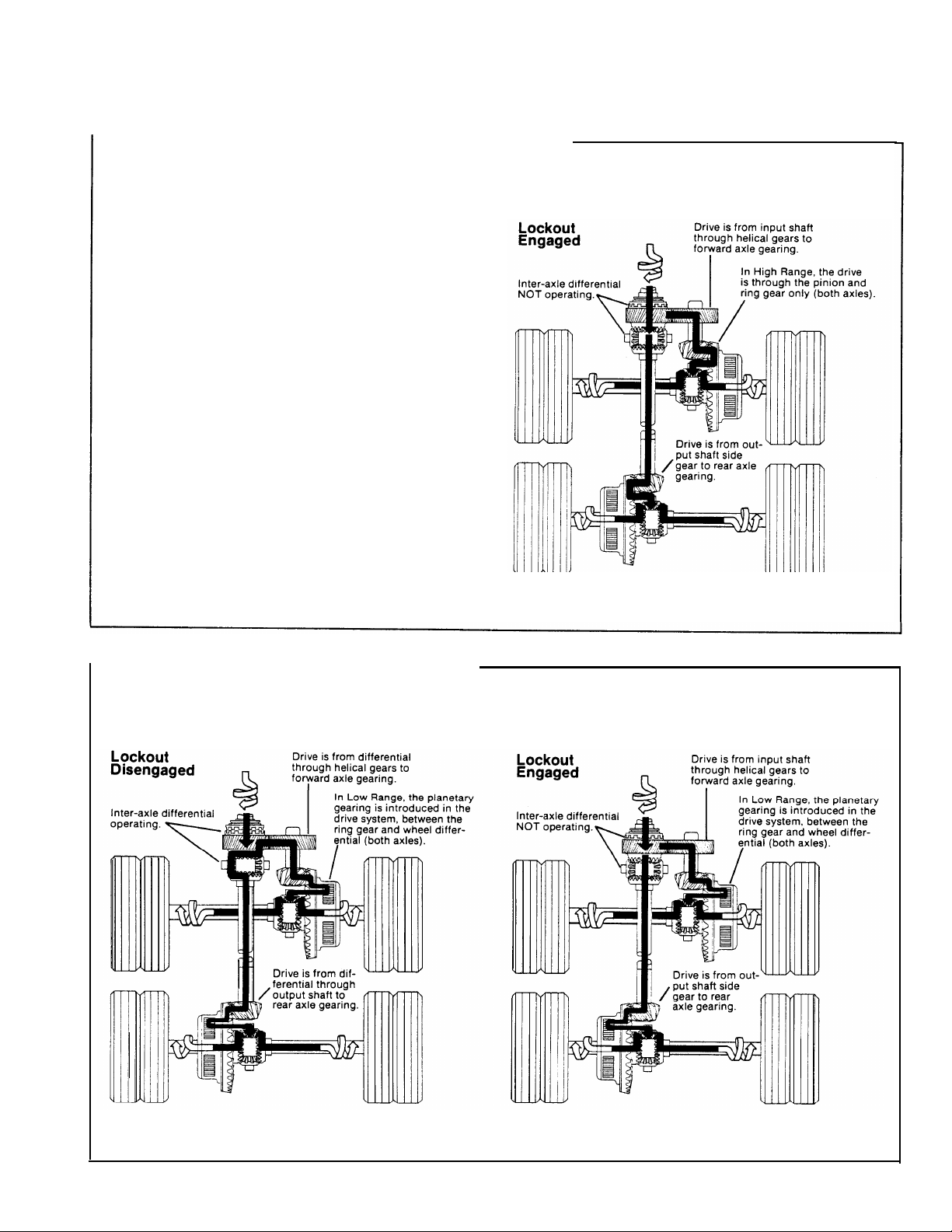
Torque Distribution in High Range
Torque (power flow) from the vehicle driveline is
transmitted to the input shaft and the inter-axle
differential spider. At this point, the differential
distributes torque equally to both sides.
For the forward axle, torque is transmitted from
the helical-side gear to the pinion helical gear,
drive pinion, ring gear, wheel differential and axle
shafts.
For the rear axle, torque is transmitted from the
output shaft side gear, through the output shaft,
inter-axle driveline, to the drive pinion, ring gear,
wheel differential and axle shafts.
INPUT
TORQUE
Torque is transmitted to both axles through inter-axle
differential action.
Page 7
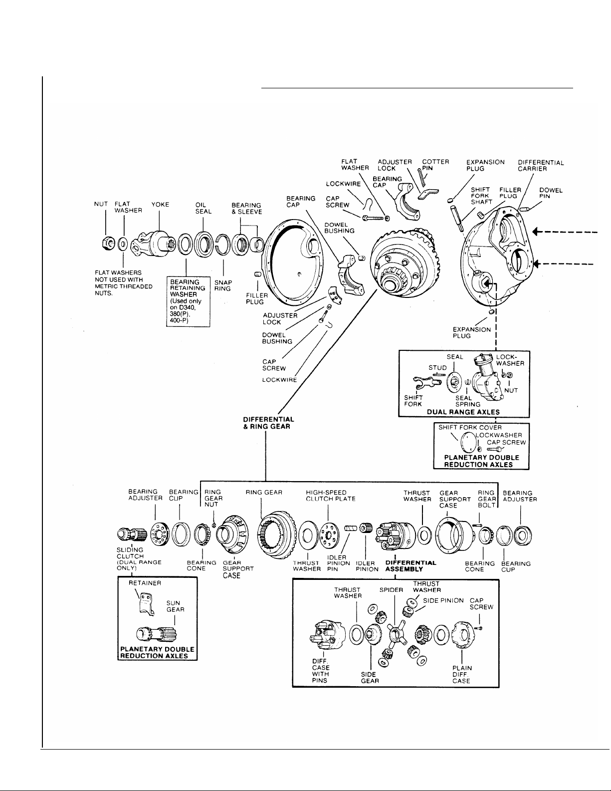
Torque Distribution in High Range (cent’d)
A lockout mechanism is incorporated in the power
divider to enable the vehicle driver to lock out the INPUT
inter-axle differential and provide maximum traction
under adverse road conditions.
In operation, an air cylinder (controlled by a cabmounted valve) shifts a sliding clutch. To lock out
inter-axle differential action, the clutch engages the
helical-side gear and causes this gear, the input shaft
and differential to rotate as one assembly. This action
provides a positive drive to both axles.
With lockout engaged, torque is distributed to both axles
without differential action. The forward axle
pinion and ring gear are driven by the helical-side
gear. The rear axle gearing is driven from the output
shaft side gear and inter-axle driveline.
NOTE: Varied road surface conditions can result
in unequal torque distribution between the two axle
assemblies.
-
Torque is transmitted to both axles without inter-axle
differential action.
TORQUE
Torque Distribution in Low Range
INPUT
TORQUE
INPUT
TORQUE
Torque is transmitted to both axles through inter-axle
differential action.
Torque is transmitted to both axles without inter-axle
differential action.
7
Page 8
Spicer Tandem Drive Axles
Differential Carrier Assembly
Forward Axle
8
Page 9
Dual Range
DT340, 310(P), 400-P
DT341, 381(P), 401-P
DT402(P), 451-P
Planetary Double Reduction
DP340, 380(P), 400-P
DP341, 381(P), 401-P
DP402(P), 451-P
IMPORTANT: Seals,
Yokes and Slingers.
Before replacing
these parts, refer to
Repair and
Replacement
Instructions for
interchangeability
information.
I
9
Page 10
Spicer®Tandem Drive Axles
Differential Carrier Assembly
Rear Axle
Dual Range RT340, 341, 380, 381, 400, 401,402, 451
Planetary Double Reduction RP340, 341, 380, 381, 400, 401, 402,451
I
10
Page 11
Lubrication
The ability of a drive axle to deliver quiet, trouble-free
operation over a period of years is largely dependent upon
the use of good quality gear lubricant in correct quantity.
The most satisfactory results can be obtained by following
the directions contained in this manual.
The following lubrication instructions represent the most
current recommendations from the Axle & Brake Division of
Dana Corporation.
Approved Lubricants
General-Gear
specification (MILSPEC) MIL-L-2105D (Lubricating Oils,
Gear, Multipurpose) are approved for use in Spicer Drive
Axles. The MIL-L-2105D specification defines performance
and viscosity requirements for multigrade oils. It super-
sedes both MIL-L-21 056, MIL-L-2105C and cold weather
specification MlL-L-l 0324A. This specification applies to
both petroleum-based and synthetic based gear lubricants
if they appear on the most current “Qualified Products List”
(QPL-2105) forMIL-L-2105D.
Note: The use of separate oil additives and/or friction
modifiers are not approved in Drive Axles.
Synthetic
superior thermal and oxidation stability, and generally
degrade at a lower rate when compared to petroleum-based
lubricants. The performance characteristics of these lubri-
cants include extended change intervals, improved fuel
economy, better extreme temperature operation, reduced
wear and cleaner component appearance. The family of
Spicer®gear lubricants represents a premium
synthetic lube which fully meets or exceeds the
requirements of MIL-L-2105D. These products, available in
both 75W-90 and 80 W-1 40, have demonstrated superior
performance in comparison to others qualified under the
MILSPEC, as demonstrated by extensive laboratory and field
testing. For a complete list of Spicerr®approved synthetic lubricants contact your local Spicer representative. See
back cover of this manual for appropriate phone number.
Makeup Lube-Maximum amount of non-synthetic makeup
lube is 100/o.
lubrications acceptable under military
based-Synthetic-based gear lubricants exhibit
quality
Viscosity/Ambient Temperature Recommendations-The
following chart lists the various SAE Grades covered by
MIL-L-2105D and the associated ambient temperature range
from each. Those SAE grades shown with an asterisk (*) are
available in the Spicer family of synthetic gear lubricants.
The lowest ambient temperatures covered by this chart are
-40°F and -40°C. Lubrication recommendations for those
applications which consistently operate below this temperature range, must be obtained through the Dana Corporation by contacting your local Spicer representative.
Grade
75W
75W-80
75W-90*
75W-140
80W-90
80W-140*
85W-140
Ambient Temperature Range
-40oF to -15°F (-40oC to -26oC)
-40°F to 80oF (-40°C to 21oC)
-40oF to 100oF (-40oC to 38oC)
-40°F and above (-40oC and above)
-150F to 100oF (-26°C to -38oC)
-150F and above (-26°C and above)
10oF and above (-12°C and above)
Lube Change Intervals
This product combines the latest manufacturing and part
washing technology.
synthetic lubricant at the factory, the initial drain is not
required.
Change the lubricant within the first 5,000 miles of
operation when not using a approved
lubricant in either a new axle or after a carrier
head replacement.
a combination of the following chart and user assessment
of the application and operating environment.
Severe Service Lubrication Change Intervals -
service applications are those where the vehicle consistently operates at or near its maximum GCW or GVW
ratings, dusty or wet environments, or consistent operation
on grades greater than 8%. For these applications, the
ON/OFF HIGHWAY portion of the chart should be used.
Typical applications are construction, logging, mining and
refuse removal.
Note:
Remove metallic particles from the magnetic filler
plug and drain plugs. Clean or replace the breather at each
lubricant change.
When filled with an approved
synthetic
Base subsequent lubricant changes on
Severe
I
I
Lubricant Type
Mineral
Based
Spicer - Approved 250,000
Synthetic
Guidelines - Lube Change Intervals for Drive Axles
On Highway
Miles
100,000
Maximum Change
Interval
Yearly
3 Years
On/Off Highway Severe
Service Miles
40,000
100,000
I
Maximum Change
Interval
Yearly
Yearly
11
Page 12
Lubrication
Changing Lube
Draining
Drain when the lube is at normal operating temperature. It will run freely
and minimize the time necessary to fully drain the axle.
Unscrew the magnetic drain plug on the underside of the axle housing
and allow the lube to drain into a suitable container. Inspect drain plug
for large quantities of metal particles. After initial oil change, these
are signs of damage or extreme wear in the axle, and inspection of the
entire unit may be warranted. Clean the drain plug and replace it after
the lube has drained completely.
Axles with Lube Pump:
divider cover and inspect for wear material in the same manner as the
drain plug. Wash the magnetic strainer in solvent and blow dry with
compressed air to remove oil and metal particles.
Remove the magnetic strainer from the power
CAUTION:
SAFE AREA. WEAR SAFETY
EXERCISE CARE
TO DIRECT COMPRESSED AIR INTO
GLASSES.
Filling
Remove the filler hole plug from
the center of the axle housing
cover and fill the axle with
approved lubricant until level
with the bottom of the hole.
Forward axles:
(0.94 liters) of lubricant through
filler hole at the top of the differential carrier near the power
divider cover.
NOTE: Lube fill capacities in the
adjacent chart are good guidelines
but will vary somewhat on the
basis of the angle the axle is
installed in a particular chassis.
Always use the filler hole as the
final reference. If lube is level with
the bottom of the hole, the axle is
properly filled.
Add two pints
Axle Installation Angles
Axles installed at angles exceeding
10 degrees or operated regularly
in areas of continuous and lengthy
grades may require standpipes to
allow proper fill levels.
For specific recommendations,
contact your local Spicer representative.
Lube Capacities*
DO NOT OVERFILL AXLES
63,&(5 Housings (Rectangular Arm)
Dual Range and PDR
Tandem Series
340, 341 . . . . . . . . . . . . . . . . . . . . . . . . . . .
380(P), 381 (P)
400-P, 401-P
402( P), 451-P . . . . . . . . . . . . . . . . . . . . .
Forward Axles: Add an additional 2 pints (0.94 liters) axle lubricant
through filler hole at the top of the differential carrier near the power
divider cover. (See photo above.)
*Capacities listed are approximate. The amount of lubricant will vary with angle of
axle as installed in vehicle chassis. Figures do not apply to housings not designed
or manufactured by Spicer.
Forward
Axle
Pints (liters)
38 (18.0)
37 (17.5)
Rear
Axle
Pints (liters)
35 (16.6)
34 (16.1)
12
Page 13
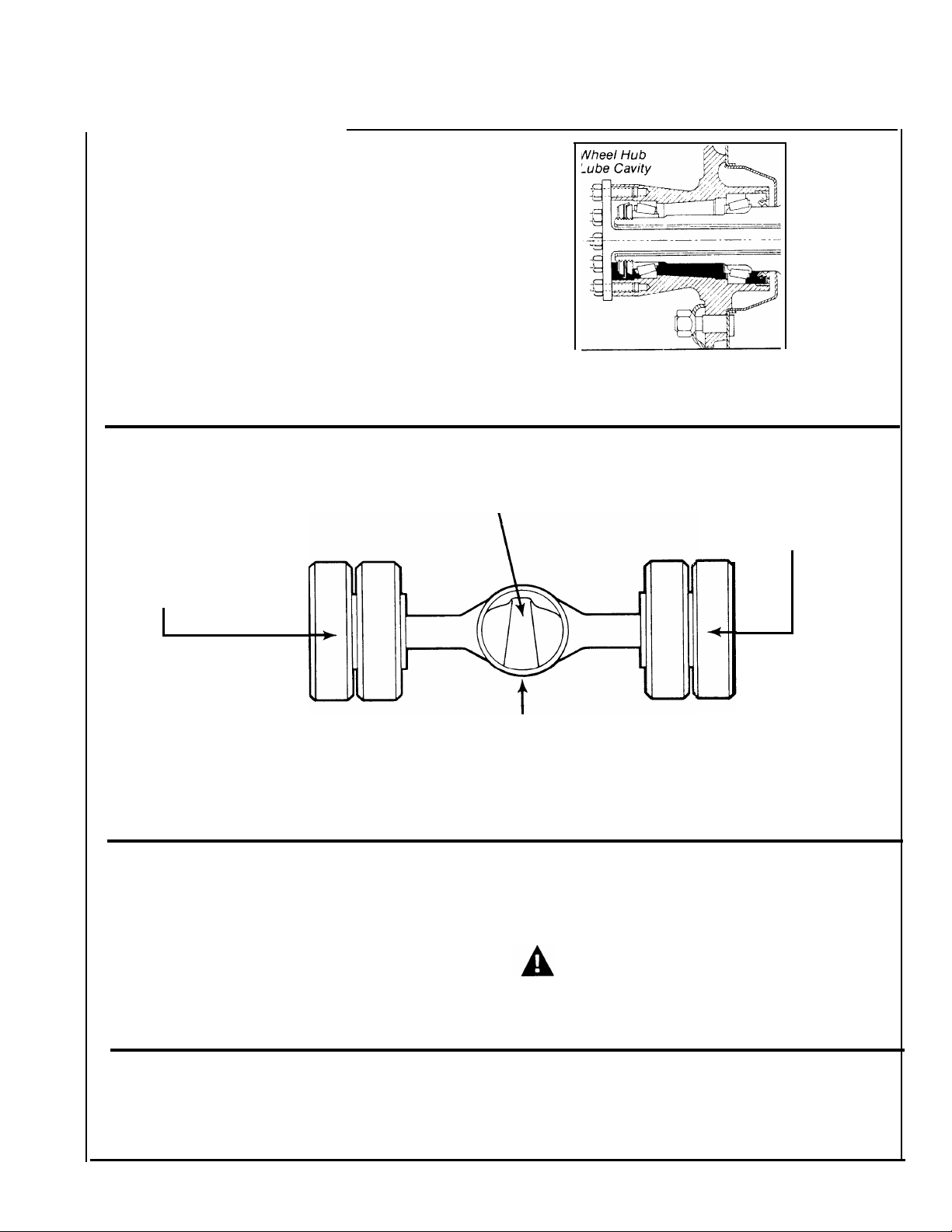
Wheel End Lubrication
IMPORTANT: In cases where wheel
equipment is being installed, either new or
after maintenance activity, the lube cavities
are empty. Bearings and seals must be
manually supplied with adequate lubricant
or they will be severely damaged before the
normal motion of the vehicle can supply
lube to the hub ends of the housing.
To avoid the risk of premature damage to being installed. There are three methods of
wheel bearings and seals, they must be doing this. The correct method will depend
“prelubed” any time the wheel equipment is
Lubrication When Hubs Have No Filler Holes (Preferred Method*)
(Follow procedure in numerical sequence.)
1. Fill axle with lube through axle housing cover filler hole.
2. Jack up left side of axle.
Maintain this position for
one minute to allow lube to
flow into wheel ends at
right side.
on the type of wheel equipment being used.
3. Jack up right side of
axle. Maintain this position
for one minute to allow
lube to flow into wheel
ends at left side.
4. With vehicle level again, add lube
through axle housing cover filler hole. The
axle should require two additional pints of
lube to bring level up to bottom of filler hole.
*The above procedure is the preferred method since it optimizes the lube supply to the
wheel end components and axle sump.
Alternate Method of Wheel End Lubrication
1. After the wheel hub seal has been installed,
charge the hub cavity with as much axle
lubricant as possible.
2. Prelube the bearings with clean axle
lubricant at installation.
NOTE: If the hub has no cavity to accept a assembly to prevent spilling lubricant on
precharge of axle lube, the bearings can be
Hubs Equipped with Lube Filler Holes
Pour a pint of standard axle lubricant into
the hub through the cavity filler hole
provided.
prepacked with a good quality grease instead
of axle lube. However, excess grease should
be removed.
CAUTION: Exercise caution when
mounting a precharged hub and drum
the brake linings.
13
Page 14
Cleaning, Inspection, Replacement
“
As the drive axle is disassembled, set all parts aside for thorough
cleaning and inspection. Careful inspection will help determine whether
parts should be reused. In many cases, the causes of premature wear or
drive axle failure will also be revealed.
Cleaning
The differential carrier assembly may be steam-cleaned while mounted in
the housing as long as all openings are tightly plugged. Once removed
from its housing, do not steam clean differential carrier or any compo-
nents. Steam cleaning at this time could allow water to be trapped in
cored passages, leading to rust, lubricant contamination, and premature
component wear. The only proper way to clean the assembly is to dis-
assemble it completely. Other methods will not be effective except as
preparatory steps in the process. Wash steel parts with ground or polished
surfaces in solvent. There are many suitable commercial solvents avail-
able. Kerosene and diesel fuel are acceptable.
WARNING: GASOLINE IS NOT AN ACCEPTABLE SOLVENT BECAUSE
OF ITS EXTREME COMBUSTIBILITY. IT IS UNSAFE IN THE
WORKSHOP ENVIRONMENT.
Wash castings or other rough parts in solvent or clean in hot solution
tanks using mild alkali solutions. If a hot solution tank is used, make
sure parts are heated thoroughly, before rinsing.
Rinse thoroughly to remove all traces of the cleaning solution. Dry parts
immediately with clean rags.
Lightly oil parts if they are to be reused immediately. Otherwise, coat
with oil and wrap in corrosion-resistant paper. Store parts in a clean, dry
place.
Inspection
Inspect steel parts for notches, visible steps or grooves created by wear.
Look for pitting or cracking along gear contact lines. Scuffing, deformation or discoloration are signs of excessive heat in the axle, usually
related to low lubricant levels or improper lubrication practices.
Before reusing a gear set, inspect teeth for signs of excessive wear.
Check tooth contact pattern for evidence of incorrect adjustment (see
Adjustment Section for correct pattern).
Inspect machined surfaces of cast or malleable parts. They must be free
of cracks, scoring, and wear. Look for elongation of drilled holes, wear
on surfaces machined for bearing fits and nicks or burrs in mating
surfaces.
Inspect fasteners for rounded heads, bends, cracks or damaged threads.
The axle housing should be examined for cracks or leaks. Also look for
loose studs or cross-threaded holes.
Inspect machined surfaces for nicks and burrs.
14
Page 15

Repair and Replacement
IMPORTANT: To achieve maximum value from an axle rebuild, replace
lower-cost parts, such as thrust washers, seals, etc. These items protect
the axle from premature wear or loss of lubricants. Replacing these
parts will not increase rebuild cost significantly.
It is also important to replace other parts which display signs of heavy
wear even though not cracked or broken. A significant portion of such a
part’s useful life has been expended and the damage caused, should the
part fail, is far in excess of its cost.
Steel Parts —
able. Worn or damaged parts should be discarded without hesitation.
Also discard mating parts in some cases. Gear sets for example,
must be replaced in sets.
Miscellaneous Parts
of these parts can be reused if damaged. Fasteners using self-locking
nylon “patches” may be reused if not damaged, but should be secured
by a few drops of Loctite #277 on the threaded surface of the hole during
installation and carefully torqued during installation.
Axle Housings
machined surfaces and the replacement of loose or broken studs.
CAUTION: ANY DAMAGE WHICH AFFECTS THE ALIGNMENT OR
STRUCTURAL INTEGRITY OF THE HOUSING REQUIRES HOUSING
REPLACEMENT. REPAIR BY WELDING OR STRAIGHTENING
SHOULD NOT BE ATTEMPTED. THIS PROCESS CAN AFFECT THE
HOUSING HEAT TREATMENT AND CAUSE IT TO FAIL COMPLETELY
WHEN UNDER LOAD.
Silicone Rubber Gasket Compound —
uses silicone rubber gasket compound to seal the majority of metal-tometal mating surfaces.
Spicer includes gasket compound and application instructions in many
repair parts kits.
It is recommended that this compound be used in place of conventional
gaskets. The compound will provide a more effective seal against lube
seepage and is easier to remove from mating surfaces when replacing
parts.
Gear sets, differential parts and bearings are not repair-
— Seals and washers are routinely replaced. None
— Repairs are limited to removal of nicks or burrs on
For more effective sealing, Spicer
Seals, Yoke & Slinger Service Information
During the 4th Quarter of 1990, Spicer began using new seals and yoke & slingers on the models in this
publication. The new seals and slingers are noticeably different from the current seals and will affect
interchangeability.
● The upgraded Seals can be used on axles originally equipped with the old seals.
● Spicer recommends the replacement of old yoke & slinger assemblies when the new seals are installed. The
old yokes and slingers will work with the new seals, but new yoke and slinger assemblies provide maximum
sealing protection and prevent premature seal wear due to poor yoke condition.
● New yoke and slinger assemblies cannot be used with the old seal design on the tandem forward axles.
● New yoke and slinger assemblies can be used with the old seal on the tandem rear pinions.
● Yoke Assembly & Oil Seal Kits contain oil seal, yoke & slinger and instructions.
● Most non-Spicer aftermarket seals will not be compatible with the new Spicer Yoke and Slinger assemblies.
● Sicer recommends the use of special installation tools conveniently packaged in a single kit (listed below).
•
Refer to Spicer parts Book AXIP-0087 and Spicer Bulletin 90-06 for additional information.
Seal Driver Installation Kit 212139
Includes:
•
126917 Driver (Rear Axle Pinion)
• 127787 Adapter (use with 126917 Driver for Forward Axle Input)
• 127786 Driver (Forward Axle Output)
15
Page 16
Adjustments
WARNING: Never work u n-
der a vehicle supported by
Wheel Bearing Adjustment
only a jack. Always support
vehicle with stands. Block
the wheels and make sure
Wheel bearings should be adjusted at regular intervals
using the following procedure:
the vehicle will not roll before releasing the brakes
Wheel End Seal
Important: Wheel end seals can be easily damaged during handling. Leave the seal in its package until installation to
prevent damage or contamination.
1. Remove:
● The outer bearing and wheel.
● The inner bearing.
● The oil seal or grease retainer and discard.
● The old wear sleeve (2-piece design only) with a ball peen hammer and discard.
Caution: Do not cut through the old wear sleeve. Damage to the housing may result.
2. Inspect:
● The spindle journal and hub bore for scratches or burns. Recondition with emery cloth as required.
Note: Deep gouges can be repaired by filling gouge with hardened gasket and smoothing with emery cloth.
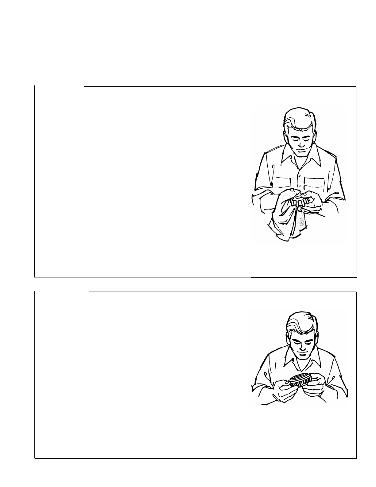
3. Clean
●
The hub cavity and bearing bores before reassembly. Be sure to remove contaminants from all recesses and corners.
● The bearings thoroughly with solvent and examine for damage. Replace damaged or worn bearings.
4. Before installation, lubricate with the same lubricant used in the axle sump.
● The inner bearing.
● The wheel seal following the directors provided by the seal supplier.
IMPORTANT: Always use the seal installation tool specified by the seal manufacturer. Using an improper tool
can distort or damage the seal and cause premature seaI failure.
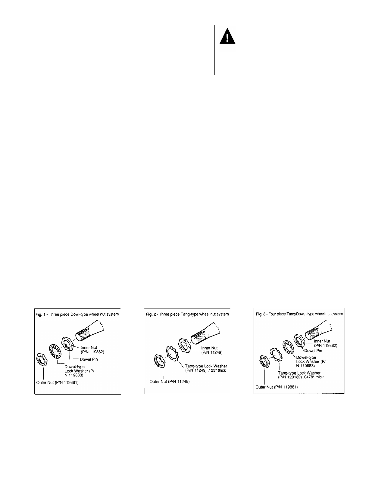
Wheel Bearing Adjustment
1. Identify the wheel nut system being installed. Three systems are available:
● Three piece Dowel-type wheel nut system-fig.1
● Three piece Tang-type wheel nut system-Fig.2
● Four piece Tang/Dowel type wheel nut system-Fig.3
J
WARNING:
Do not mix spindle nuts and lock washers from different systems. Mixing spindle nuts and lock washers can
cause wheel separation.
NOTE:
The lock washer for a four piece-dowel-type wheel system is thinner than the lock washer for a three piece tang-
type wheel nut system and is not designed to bear against the inner nut.
16
Page 17
2. inspect the indle and nut threads for corrosion and ean thoroughly or replace as required.
Note: Proper assembly and adjustment is not possible if the spindle or nut threads are corroded.
● Inspect the tang-type washer (if used). Replace the washer if the tangs are broken, cracked, or damaged.
3. Install the hub and drum on the spindle with care to prevent damage or distortion to the wheel seal.
* CAUTION: A wheel dolly is recommended during installation to make sure that the wheel seal is not damaged
by the weight of the hub and drum. Never support the hub on the spindle with just the inner bearing and seal.
This can damage the seal and cause premature failure.
●
Completely fill the hub cavity between the inner and outer bearing races with the same lubricant used in the axle sump.
4. Before installation, lubricate the outer bearing with the same lubricant used in the axle sump.
Note: Lubricate only with clean axle lubricant of the same type used in the axle sump. Do not pack the bearing with
grease before installation. Grease will prevent the proper circulation of axle lubricant and may cause wheel seal failure.
5. ● Install the outer bearing on the spindle.
● Install the inner nut on the spindle.
● Tighten the inner nut to 200 lbs. ft. (271 N. M.) while rotating the wheel hub.
*
CAUTION: Never use an impact Wrench to adjust wheel bearings. A torque wrench is required to assure that
the nuts are property tightened.
6.
Back-off the inner nut one full turn. Rotate the wheel hub.
Re-tighten the inner nut to 50 lbs. ft. (68 N. M.) while rotating the wheel hub.
7.
Back-off the inner nut exactly 1/4 turn.
8.
Note:
This adjustment procedure allows the wheel to rotate freely with 0.001”-0.005” (0.025mm to 0.1 27mm) end-play.
9. Install the correct lock washer for the wheel nut system being used.
THREE PIECE TANG-TYPE LOCK WASHER SYSTEM (see Fig. 2).
*Install the Tang-type lock washer on the spindle.
IMPORTANT: Never tighten the inner nut for alignment. This can preload the bearing and cause premature failure.
*Install the outer nut on the spindle and tighten to 250 lbs. ft. (339 N.M.).
*Verify end-play (see End Play Verification Procedure)
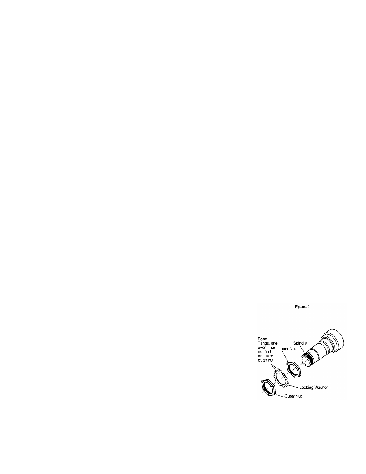
*After verifying end play, secure wheel nuts by bending one of the locking
washer tangs over the outer wheel nut and another tang over the inner wheel
nut as shown in Figure 4. (below)
THREE PIECE DOWEL-TYPE LOCK WASHER SYSTEM (see Fig.1)
* Install the Dowel-type lock washer on the spindle.
Note: If the dowel pin and washer are not aligned,
remove washer, turn it over
and reinstall. If required, loosen the inner nut just enough for alignment.
IMPORTANT: Never tighten the inner nut for alignment. This can preload the bearing and cause premature failure.
*Install the outer nut on the spindle and tighten to 350 lbs. ft. (475 N.M.).
*Verify end-play (see End Play Verification Procedure)
17
Page 18
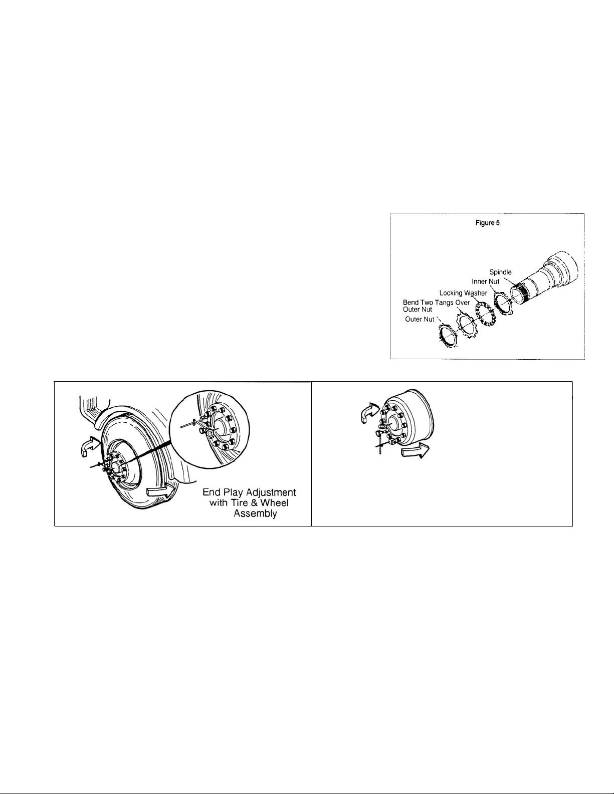
FOUR PIECE TANG/DOWEL-TYPE LOCK WASHER SYSTEM (see Fig. 3)
* First, install the Dowel-type lock washer on the spindle.
Note: If the dowel pin and washer are not aligned, remove washer, turn it over and reinstall. If required loosen the in-
ner nut just enough for alignment.
IMPORTANT:
Never tighten the inner nut for alignment. This can preload the bearing and cause premature failure.
* Install the Tang-type lock washer on the spindle.
* Install the outer nut on the spindle and tighten to 250
lbs. ft. (339 N m.)
* Verify end-play (see End Play Verification Procedure)
* After verifying end play, secure the outer nut by bending two opposing (180ç apart) tangs of the locking washer
over the outer nut as shown in Figure 5 (below).
10. Install
* New gasket at axle shaft flange.
* axle shaft.
* Axle flange nuts and tighten to specified torque.
11. Lubricate axle wheel ends (see Wheel End Lubrication Procedure)
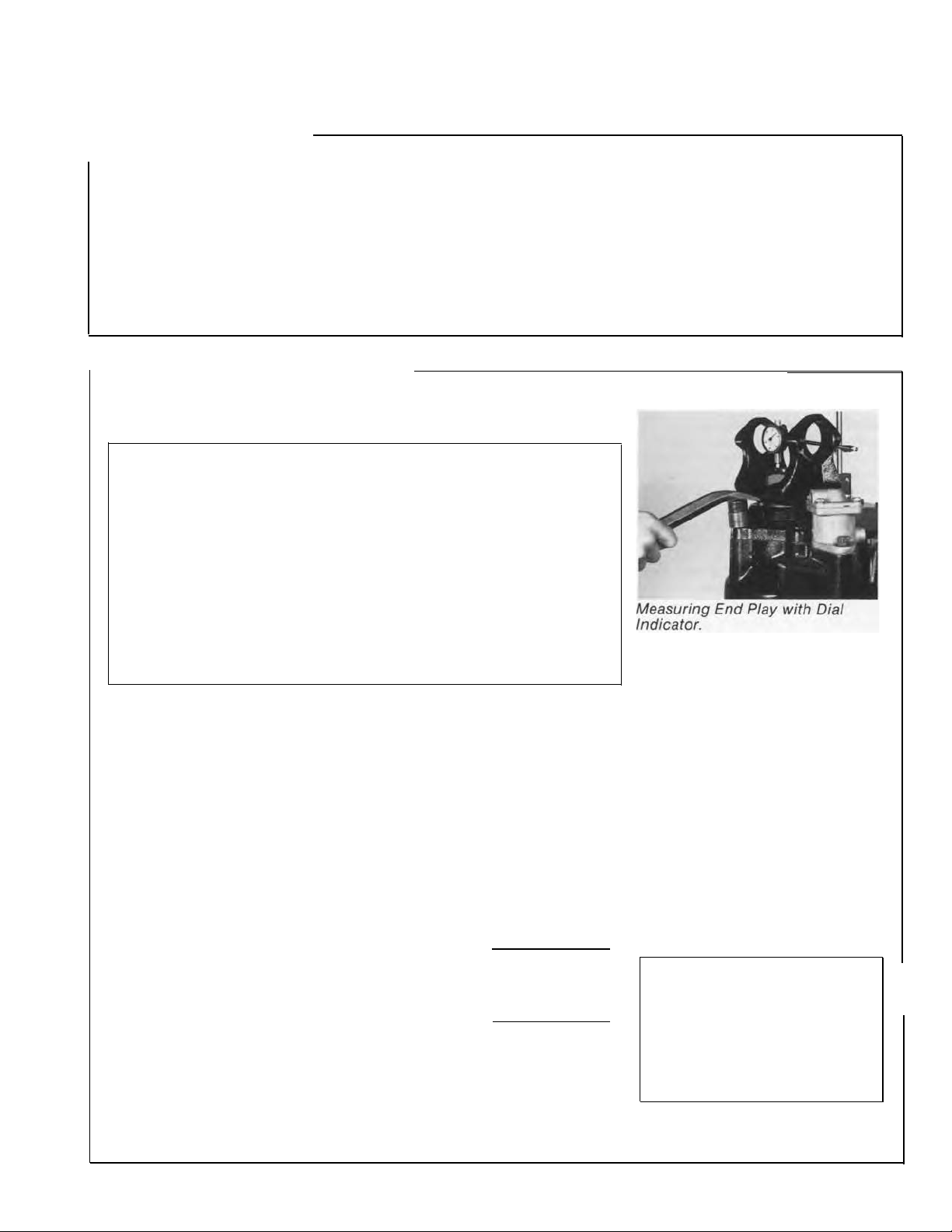
End Play Verification Procedure
Verify that end-play meets specification using a dial indicator. An indicator with 0.001" (0.03 mm) resolution is required. Wheel end play is the
free movement of the tire and wheel assembly along the spindle axis.
a. Attach a dial indicator with its magnetic base to the hub or brake drum as shown below:
I
With indicator mounted at bottom,
Push/Pull at sides of drum
End Play Adjustment
with Wheel hub
Fig. 4 End Play Measurement
b. Adjust the dial indicator so that its plunger or pointer is against the end of the spindle with its line of action approximately parallel to the axis of the spindle.
c. Grasp the wheel assembly at the 3 o'clock and 9 o'clock positions. Push the wheel assembly in and out while
oscillating it to seat the bearings. Read bearing end play as the total indicator movement.
* CAUTION: If end play is not within specification, readjustment is required.
End Play Re-adjustment Procedure
Excessive End Play -
If end play is greater than .005' (.127 mm), remove the outer nut and pull the lock washer away
from the inner nut, but not off the spindle. Tighten the inner nut to the next alignment hole of the dowel-type washer (if
used). Reassemble the washer and torque the outer nut. Verify end play with a dial indicator.
Insufficient End Play - If end play is not present, remove the outer nut and pull the lock washer away from the inner
nut, but not off the spindle. Loosen the inner nut to the next adjustment hole of the dowel-type washer (if used). Reassemble the washer and re-torque the outer nut. Verify end play with a dial indicator.
Fine Tuning the End Play -
If, after performing the readjustment procedures, end play is still not within the .001"-.005"
(.025 mm to.127 mm) range, disassemble and inspect the components. If parts are found to be defective, replace the
defective parts, reassemble and repeat wheel bearing adjustment procedure. Verify end play with a dial indicator.
18
Page 19
Differential Carrier
I
Adjustments help provide optimum axle life and performance by correctly
positioning bearings and gears under load.
The tandem axles covered in this manual require the following adjustments:
Bearing Preload:
performed for both pinion and differ-
ential bearings. It maintains proper
gear alignment by creating correct
bearing cone and cup relationship for
free rotation under load. The pinion
pilot bearing does not require
load adjustment.
Adjust Input Shaft End Play
Specifications: Input shaft end play requirements will vary with operat-
ing conditions, mileage and rebuild procedures. These variations are
shown in the following chart.
This adjustment is
a pre-
Ring Gear Tooth Contact: This adjust-
ent positions ring gear and pinion
for best contact under load. Correct in the inter-axle differential. Proper
adjustment distributes torque evenly adjustment helps maximize life of all
over gear
gear set life.
teeth and helps maximize
Input Shaft End Play (Forward Axles):
This adjustment controls gear mesh
power divider parts.
Input
New or Rebuild with new parts
0.003" to 0.007"
Shaft End Play Chart
NOTE: Because of manufacturing
variations in individual parts,
correctly adjusted end play could
Rebuild with reused parts
0.013" to 0.017"
vary 0.010", after the unit is
rotated.
Acceptable End Play Tolerances when measuring as
a regular maintenance procedure with axle in truck.
Up to 0.060" with over 100,000
miles or 1 year service off-road.
NOTE: If end play exceeds limits,
disassemble power divider and
replace worn parts.
Up to 0.040" with less than 100,000
miles or 1 year service on-road.
Measure and Adjust End Play
IMPORTANT:
Button between the input and output shafts. End play tolerances are the
same for axles with or without this Spring and Button. However, end play
measurement procedure is different than-described below. Refer to Service
Bulletin Supplement at back of this manual for procedure variances.
1. With power divider assembled to differential carrier, measure end
pay with dial indicator positioned at yoke end of input shaft. Move
input shaft axially and measure end play. If end play is not correct (see
chart), adjust as follows.
2. Remove input shaft nut, flat washer and yoke. Remove bearing cover
cap screws and lockwashers. Remove cover and shim pack.
3. To increase end play, add shims:
desired end play . . . . . . . . . . . . . . . . . . . . . . . . . . . . . . . . 0.003" to 0.007"
pleasured endplay (Step)....... . . . . . . . . . . . . . . . . 0.001" - 0.001"
Add shims to provide desired end play . . . . . . . . . . . . . 0.002" to 0.006"
4. To decrease end play, remove shims:
Measured endplay (Step 1l) . . . . . . . . . . . . . . . . . . . . . . . 0.015" - 0.015"
desired end play . . . . . . . . . . . . . . . . . . . . . . . . . . . . . . . . 0.003" to 0.007"
Remove shims to provide desired end play . . . . . . . . . 0.012" to 0.008"
5. To reassemble input shaft, install the adjusted shim pack and bearing cover. Install cap screws and lockwashers. Torque screws to 75-85
ft-lbs. (101-115 N.m).
NOTE: If difficulty is experienced in achieving correct torque on the
input yoke nut, torque the nut with truck on the ground and axle shafts
installed.
In September 1988, Spicer added a Spring and a Thrust
6. Install yoke, flat washer and nut.
Tighten nut snugly. Tap end of
input shaft lightly to seat bearings.
7. Measure input shaft end play
with dial indicator. If end play is
still incorrect, repeat Steps 2
through 6.
8. With end play correct, seal shim
pack to prevent lube Ieakage, then
torque input shaft nut and cover
cap screws (see chart).
NOTE: When power divider has
been disassembled and reassembled, it may be desirable to adjust
end play by measuring bearing
cover clearance and calculating
shim pack size. For procedures,
see page 42.
Torque Chart
Input
Shaft Nut Ft-lbs.
1-5/8-18 780-960
*M42
X 1.5 840-1020
Bearing Cover
Cap Screw
1/2-13 75-85
(Grade 5)
*Metric Nut used on Axles produced after 7/1 /95
N´m
1057-1301
1140-1383
101-115
19
Page 20
Adjustments
Pinion Bearing Preload
Most late model axles are provided with a “press-fit” outer bearing on
the drive pinion. Some of the early model axles use an outer bearing
which slips over the drive pinion. Procedures for adjusting both types
of pinion bearing design are contained in this section.
Adjust Pinion Bearing Preload for Axles with
.
“Press-fit” Outer Pinion Bearings
Trial Build-up
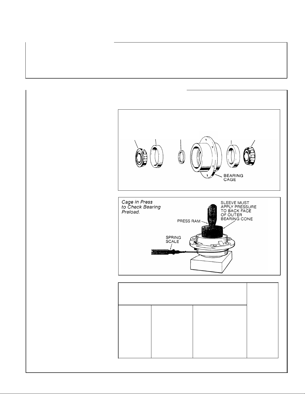
1. Assemble pinion bearing cage,
bearings and spacer (without drive
pinion or oil seal). Center bearing
spacer between two bearing cones.
NOTE: When new gear set or
pinion bearings are used, select
nominal size spacer from the speci-
fication chart below. If original
parts are used, use spacer removed
during disassembly.
2. With the bearings well lubri-
cated, place the assembly in the
press. Position sleeve so that load
is applied directly to the back-face
of the outer bearing cone.
3. Apply press load (see chart
below) to the assembly and check
rolling torque. Wrap soft wire
around the bearing cage, attach
spring scale and pull. Preload is
correct when torque required to
rotate the pinion bearing cage is
from 10-20 inch-pounds. This
specification is translated into
spring scale readings in the chart
below.
4. If necessary, Adjust Pinion
Bearing Preload by changing the
pinion bearing spacer. A thicker
spacer will decrease preload. A
thinner spacer will increase
preload.
IMPORTANT: Once correct bear-
ing preload has been established,
note the spacer size used. Select a
spacer 0.001” larger for use in the
final pinion bearing cage assembly.
The larger spacer compensates
for slight “growth” in the bear-
ings which occurs when they are
pressed on the pinion shank. The
trial build-up will result in proper
pinion bearing preload in three
of four cases.
IMPORTANT: Do not assume that
all assemblies will retain proper
preload once bearings are pressed
on pinion shank. FINAL PRELOAD
TEST MUST BE MADE IN EVERY
CASE.
I
Assemble these Parts for
Trial Build-up.
INNER INNER
BEARING BEARING SPACER
CONE
Axle Models
Forward Axles
D340, 380(P),
400-P
D341, 381(P),
401-P, 402(P),
451-P
Rear Axles
(ail models)
CUP
Specifications for Pinion Bearing
Trial Build-up Preload Test
(“Press-fit” Outer Pinion Bearings)
Nominal Bearing
Spacer Thickness
in.
0.638
0.496
0.638
BEARING
(vARIABLE)
mm
16.21
12.60
16.21
13.5-15.5
Press Loads
Tons
17-19
14-15
OUTER
BEARING
CUP
Metric Tons
12.2-14.0
15.4-17.2
12.7-13.6
OUTER
BEARING
CONE
Spring
Scale Reading
(without
pinion seal)
(for 10-20
in-lbs. torque)
(1.1-2.3 N•m)
lbs. kgs.
3-7 1.4-3.2
3-7 1.4-3.2
4-8 1.8-3.6
20
Page 21
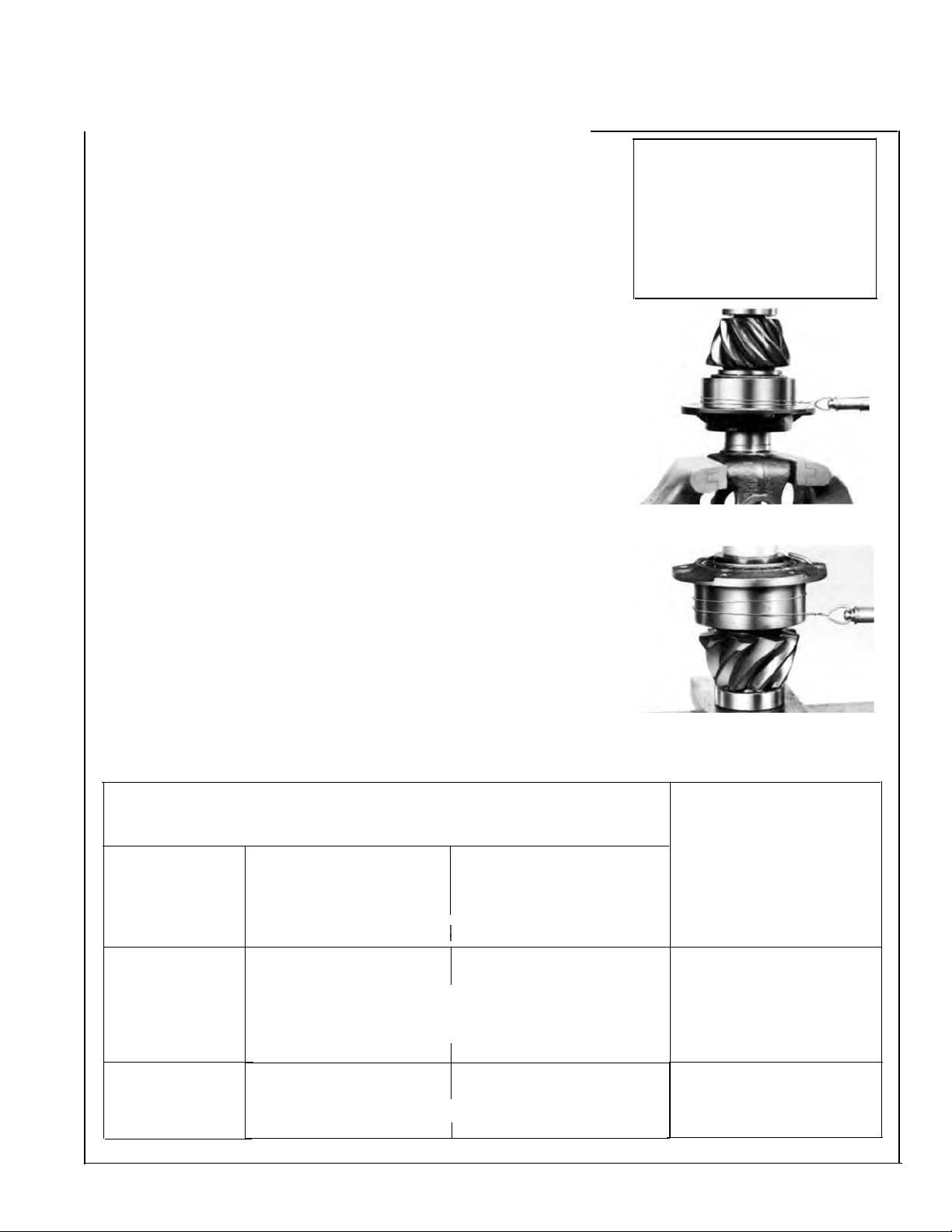
Final Pinion Bearing Preload Test
1. Assemble the complete pinion bearing cage unit as recommended
in the assembly section of this manual.
NOTE:
disassembly during bearing adjustment procedure, use a dummy yoke
if available) in place of helical gear.
2. Apply clamp load to the pinion bearing cage assembly. Either install
.
the yoke (or helical gear) and torque the pinion nut to specifications or
use a press to simulate nut torque (see chart below).
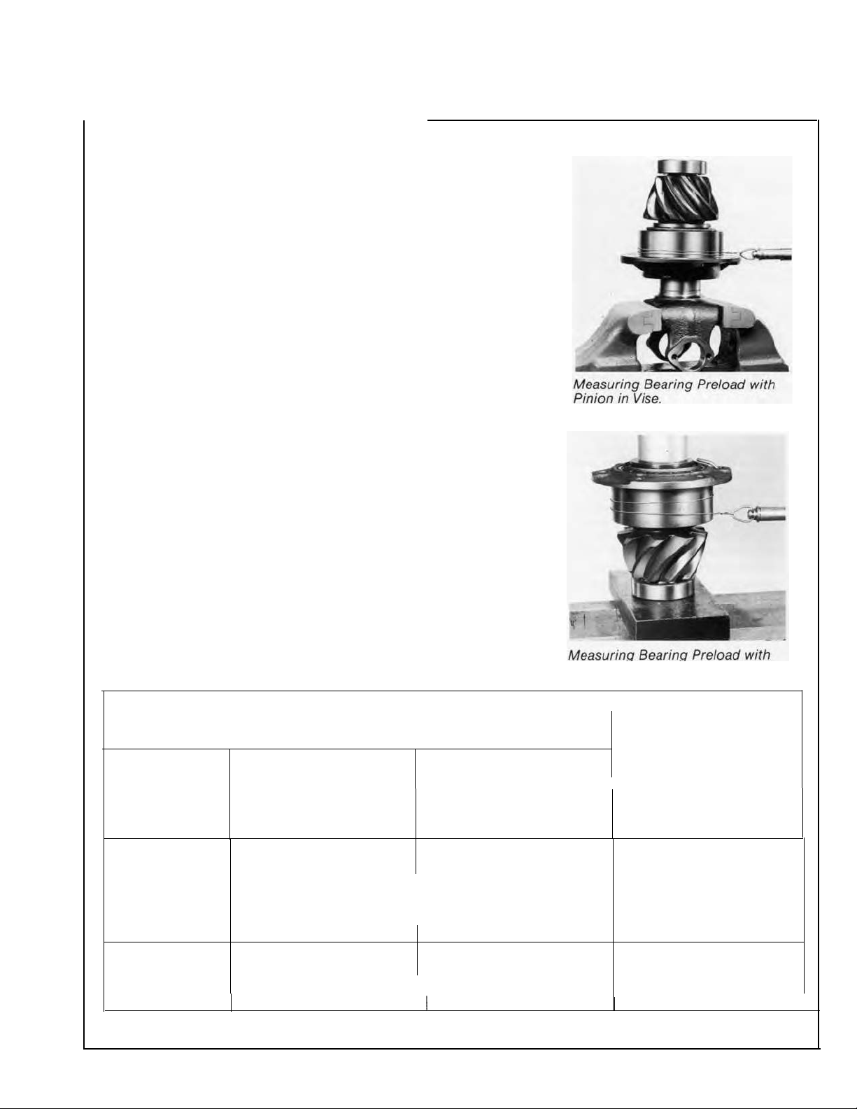
Vise Method
vise, clamping yoke firmly.
Press Method
load is applied directly to the back-face of the outer bearing cone.
.
3. Measure Pinion Bearing Preload -
assembly rolling torque. To use the spring scale, wrap soft wire around
the bearing cage, attach the scale and pull. Preload is correct when
torque required to rotate the pinion bearing cage is from 15 to 35 inch
pounds. This specification is translated into spring scale readings in the
chart below.
4. Adjust Pinion Bearing Preload -
preload. Disassemble the pinion bearing cage as recommended in this
manual and change the pinion bearing spacer. A thicker spacer will
decrease preload. A thinner spacer will increase preload.
IMPORTANT:
grind spacers. These practices can lead to loss of bearing preload and
gear or bearing failure.
Forward axle pinion is equipped with helical gear. For easier
-
If the yoke and nut are used, mount the assembly in a
- If a press is used, position a sleeve or spacer so that
Use a spring scale to test the
If necessary, adjust pinion bearing
Use the correctly sized spacer. Do not use shim stock or
Specifications for Final Pinion
Bearing Preload Test
("Press-fit" Outer Pinion Bearing)
Nut Torque
Axle Models
Forward Axles
D340, 380(P),
400-P
D341, 381(P),
401-P, 402(P),
451 -P
Rear Axles
(all models)
*Torque nut to 840 ft-lbs. (1139 N´m), then continue tightening nut to align nut slot to nearest hole in pinion shank.
Ft-lbs.
SELF-LOCKING N UT
560-700
SELF-LOCKING NUT
780-960
SLOTTED NUT & ROLL PIN
840*
METRIC NUT (After 7-1-95)
840-1020
560-700
METRIC NUT (After 7-1-95)
575-703
N.m
759-949
1057-1301 17-19
1139* 17-19
1140-1383
759-949
774-955
Press Loads
Tons
13.5-15.5 12.2-14.0
17-19
14-15
Metric Tons
15.4-17.2
15.4-17.2
15.4-17.2
12.7-13.6
Spring Scale Reading
(without pinion seal)
(for 15-35 in-lbs. torque)
lbs.
5-12
5-12
5-12
6-14 2.7-6.4
(1.7-4 N.m)
kgs.
2.3-5.4
2.3-5.4
2.3-5.4
21
Page 22
Adjustments
Adjust Pinion Bearing Preload for Axles with
ñSlip-fitî Outer Pinion Bearings
1. Lubricate bearings and assemble the drive pinion, bearings, and
pinion bearing cage as recommended in the assembly section of this
manual. Use the pinion bearing spacer removed from the axle during
disassembly. If the original spacer cannot be used, install the nominal
spacer recommended in the adjacent chart.
NOTE: Forward axle pinion is equipped with helical gear. For easier
disassembly during bearing adjustment procedure, use a dummy yoke
(if available) in place of helical gear.
2. Apply clamp load to the pinion bearings. Install the yoke (or helical
gear) and torque the nut to specification or use a press to simulate nut
torque by applying pressure to the assembly (see chart below).
Vise Method -
in a vise, clamping yoke firmly.
Press Method -
load is applied directly to the back-face of outer pinion bearing.
3. Measure Pinion Bearing Preload - Use a spring scale to test the
assembly rolling torque. To use the spring scale, wrap a soft wire around
the bearing cage, attach the scale and pull. Preload is correct when
torque required to rotate the pinion bearing cage is from 15 to 35 inch
pounds. This specification is translated into spring scale readings in the
chart below.
4. Adjust Pinion Bearing Preload -
preload. Disassemble the pinion bearing cage as recommended in this
manual and change the pinion bearing spacer. A thicker spacer will
decrease preload. A thinner spacer will increase preload.
IMPORTANT: Use the correctly sized spacer. Do not use shim stock or
grind spacers. These practices can lead to loss of bearing preload and
gear or bearing failure.
If the yoke and nut are used, mount the assembly
If a press is used, position a sleeve or spacer so that
If necessary, adjust pinion bearing
Nominal Pinion
Bearing Spacers
Spacer Thickness
Axle Model
Forward Axles
D340, 380(P), 400-P
D341, 381(P), 401-P,
402(P), 451-P
Rear Axles
(all models)
Measuring Bearing Preload with
Pinion in Vise.
in. mm
0.638 16.205
0.492 12.497
0.638 16.205
Measuring Bearing Preload with
Pinion in Press.
Spring Scale Reading
(without pinion seal)
(for 15-35 in-lbs. torque)
lbs.
5-12
5-12
5-12
Axle Models
Forward Axles
D340, 380(P),
400-P
D341, 381 (P),
401-P, 402(P),
451-P
Specifications for Final Pinion
Bearing Preload Test
("Press-fit" Outer Pinion Bearing)
Nut Torque
Ft-lbs. N.m
Tons Metric Tons
SELF-LOCKING NUT
I
560-700
759-949 13.5-15.5 12.2-14.0
SELF-LOCKING NUT
780-960
1057-1301
17-19
SLOTTED NUT & ROLL PIN
840*
11 39*
17-19
Press Loads
15.4-17.2
15.4-17.2
METRIC NUT (After 7-1-95)
840-1020
1140-1383
17-19
15.4-17.2
Rear Axles
(all models)
560-700
759-949
14-15
12.7-13.6
6-14
METRIC NUT (After 7-1-95)
575-703
*Torque nut to 840 ft-lbs. (1.139 N´m), then continue tightening nut to align nut slot to nearest hole in pinion shank.
774-955
(1.7-4 N.m)
kgs.
2.3-5.4
2.3-5.4
2.3-5.4
2.7-6.4
22
Page 23
Differential Bearing Preload and Ring Gear
Backlash Adjustment
Correct differential bearing preload insures proper location of these
bearings under load and helps position the ring gear for proper gear
tooth contact.
(Follow procedures in numerical sequence.)
Adjust Diff. Bearing Preload
1. Lubricate differential bearings.
IMPORTANT: When installing
bearing caps and adjuster, exert
care not to cross threads.
2. Install adjusters and bearing
caps. Tighten bearing cap screws
finger-tight. If this is difficult,
use a hand wrench.
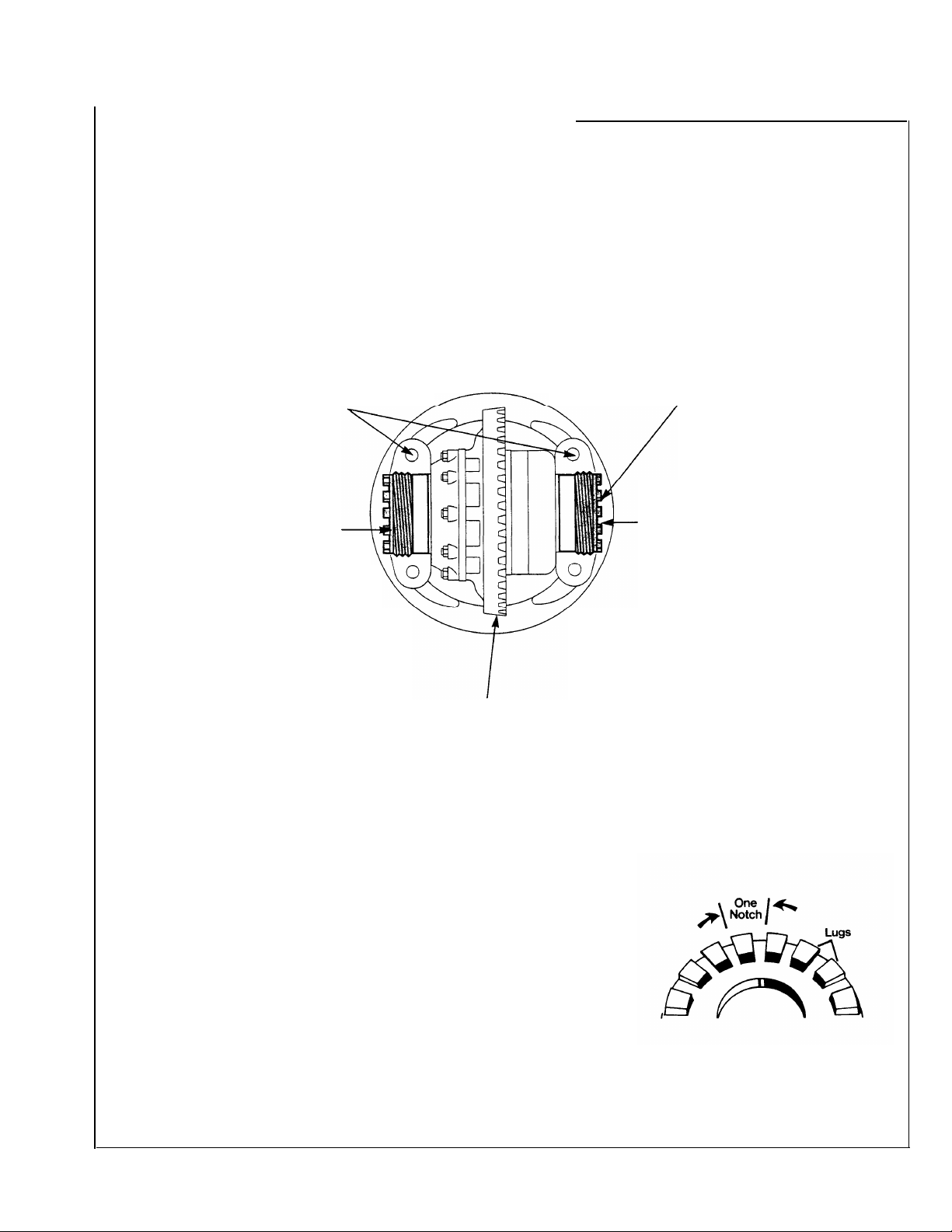
4. Tighten the bearing adjuster
on the back-face side of the ring
gear until there is no backlash.
This can be tested by facing the
ring gear teeth and pushing the
gear away from the body while
gently rocking the gear from side
to side. There should be no free
movement.
Rotate the ring gear and check
for any point where the gear may
bind. If such a point exists,
loosen and retighten the back
side adjuster. Make all further
adjustments from the point of
tightest mesh.
NOTE: Ring gear position for rear
axle is illustrated.
6. Measure backlash with a dial indicator.
USED GEARING
NEW GEARING
If backlash is incorrect, proceed as described below to readjust.
— Reset to backlash recorded before disassembly.
— Backlash should be between 0.006” and 0.016”.
3. Loosen the bearing adjuster
on the same side as the ring gear
teeth until its first thread is
visible.
5. At teeth side of ring gear,
tighten adjuster until it contacts
the bearing cup. Continue tighten-
ing adjuster two or three notches
and this will preload bearings and
provide backlash.
/
/
Adjust Ring Gear Backlash
To
add
adjuster on the teeth side of the ring
gear several notches. Loosen the
opposite adjuster one notch.
Return to adjuster on teeth side of
the ring gear and tighten adjuster
until it contacts the bearing cup.
Continue tightening the same adjuster 2 or 3 notches. Recheck
backlash.
backlash: Loosen the
To
remove
adjuster on the teeth side of the ring
gear several notches. Tighten the
opposite adjuster one notch.
Return to adjuster on teeth side of
ring gear and tighten adjuster until it
contacts the bearing cup. Continue
tightening the same adjuster 2 or 3
notches. Recheck backlash.
backlash: Loosen the
Moving adjuster one notch is the
movement of the lead edge of one
adjuster lug to the lead edge of the
next lug past a preselected point.
23
Page 24
Adjustments
R ing Gear and Pinion Tooth Contact
NOTE: Rear axle gearing is shown in the following instructions. Correct
tooth contact patterns and adjustments are the same for
rear axles.
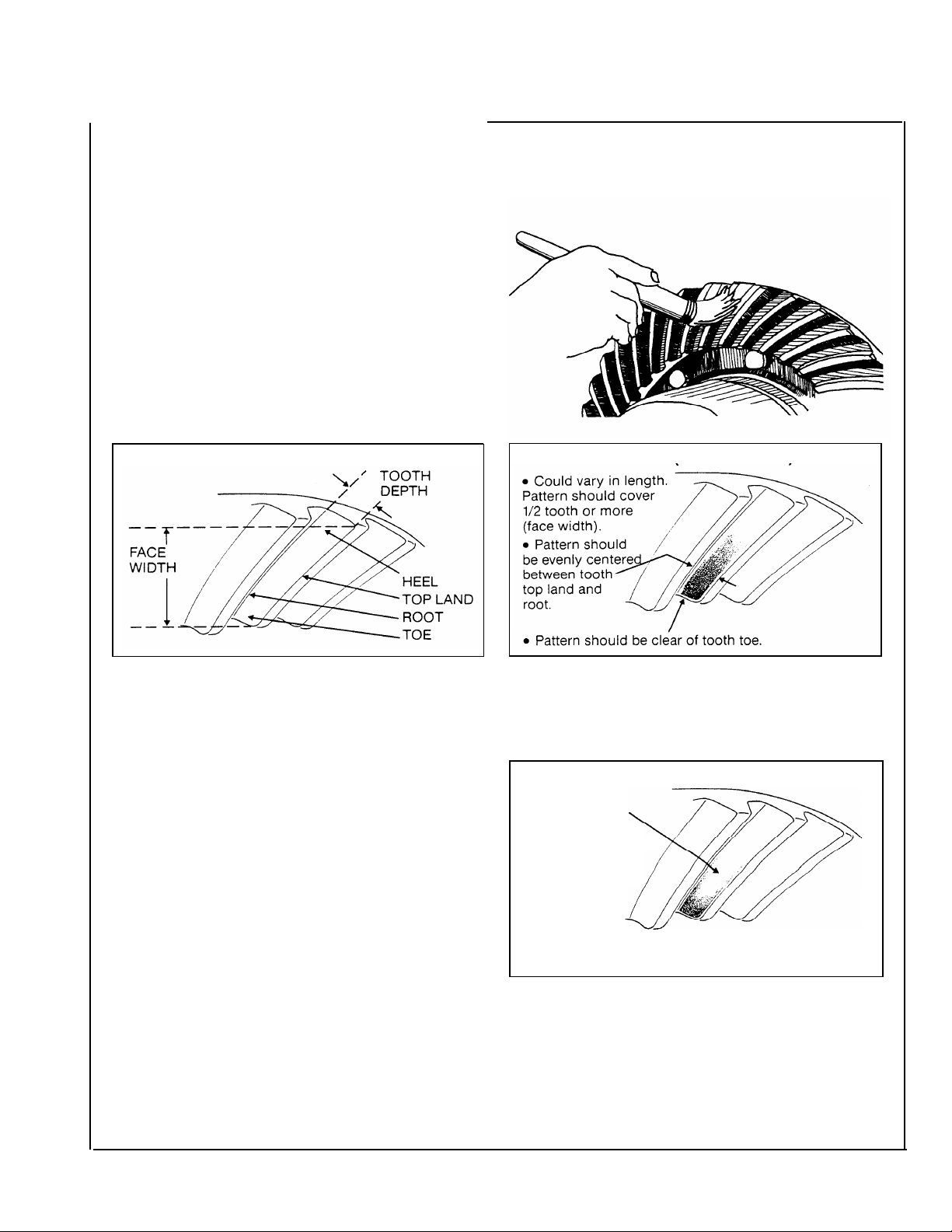
Check Tooth Contact Pattern (NEW GEAR)
Paint twelve ring gear teeth with marking compound
and roll the gear to obtain a contact pattern. The correct
pattern is well-centered on the ring gear tooth with
lengthwise contact clear of the to the Iength of the
pattern in an unloaded condition is approximately onehalf to two-thirds of the ring gear tooth in most models
and ratios.
forward and
RING GEAR TOOTH NOMENCLATURE
Check Tooth Contact Pattern (USED GEAR)
Used gearing will not usually display the square,
even contact pattern found in new gear sets. The
gear will normally have a “pocket” at the toward
of the gear tooth which tails into a contact line
along the root of tooth. The more use a gear has
had, the more the line becomes the dominant
characteristic of the pattern.
Adjust used gear sets to display the same contact
pattern observed before disassembly. A correct
pattern is clear of the toe and centers evenly along
the face width between the top land and root.
Otherwise, the length and shape of the pattern are
highly variable and is considered acceptable as
long as it does not run off the tooth at any point.
CORRECT PATTERN (NEW GEARING)
CORRECT PATTERN (USED GEARING)
●
Pocket may be
extended.
●
Pattern along
face width
could be longer.
the
24
Page 25

Adjust Tooth Contact Pattern
If necessary, adjust the contact pattern by moving the ring gear and
drive pinion. Ring gear position controls the backlash. This adjustment
moves the contact pattern along the face width of the gear tooth. Pinion
position is determined by the size of the pinion bearing cage shim pack. It
controls contact on the tooth depth of the gear tooth.
These adjustments are interrelated. As a result, they must be considered together even though the pattern is altered by two distinct
operations. When making adjustments, first adjust the pinion, then the
backlash. continue this sequence until the pattern is satisfactory.
Adjust Pinion Position
If the gear pattern shows incorrect tooth depth contact, change drive
pinion position by altering the shim pack. Used gears should achieve
proper contact with the same shims removed from the axle at disassembly.
INCORRECT PATTERN
INCORRECT PATTERN
/
● Pattern too close to tooth top ‘land and off center.
If the pattern is too close to the top land of the
gear tooth, remove pinion shims.
Ž Pattern’ too close or off tooth root.
If the pattern is too close to the root of the gear
tooth, add pinion shims.
NOTE: Check ring gear backlash after each shim change and adjust if necessary to maintain the 0.006” to
0.016” specifications.
If the gear pattern shows incorrect face width contact, change backlash.
INCORRECT PATTERN
INCORRECT PATTERN
● Pattern too close to edge of tooth toe.
With the pattern concentrated at the toe (too far
down the tooth), add backlash by loosening the
bearing adjuster on the teeth side of ring gear several notches. Loosen the opposite adjuster one notch.
Return to adjuster on teeth side of ring gear and
tighten adjuster until it contacts the bearing cup.
Continue tightening the same adjuster 2 or 3
notches. Recheck backlash.
• Pattern too far along tooth toward tooth heel.
If the pattern is concentrated at the heel (too
far up the tooth), remove backlash by loosening the
bearing adjuster on the teeth side of ring gear several notches. Tighten the opposite adjuster one notch
Return to adjuster on teeth side of ring gear and
tighten adjuster until it contacts the bearing cup.
Continue tightening the same adjuster 2 or 3
notches. Recheck backlash.
25
Page 26

Fastener Tightening Specifications
Specifications are for all axle models unless specified otherwise.
—
●
Correct tightening torque values are extremely important to assure
long Spicer Axle life and dependable performance. Under-tightening
of attaching parts is just as harmful as over-tightening.
●
Exact compliance with recommended torque values will assure the
best results.
●
The data includes fastener size, grade and torque tightening values.
Axle models are included to pinpoint identification of fasteners for
your particular axle.
●
To determine bolt or cap screw grade, check for designation stamped
on bolt head (see illustration).
NOTE 1: METRIC NUTS used on Axles produced after 7-1-95. Reference chart on page 76
26
REFERENCE MISC. TORQUE FASTENING CHART ON PAGE 76
Grade
Grade
5
8
.
Page 27

Dual Range
DT340, DT380(P), DT400-P
DT341, DT381(P), DT401-P
DT402(P), DT451-P
Planetary Double Reduction
DP340, DP380(P), DP400-P,
DP341 , DP381(P), DP401-P,
DP402(P), DP451-P
REFERENCE MISC. TORQUE FASTENING CHART ON PAGE 76
NOTE 1: METRIC NUTS used on Axles produced after 7-1-95. Reference chart on page 76
27
Page 28

Fastener Tightening Specifications:
Specifications
Rear Axles
are for all axle models unless specified otherwise.
Dual Range RT340, 341,380,
Planetary Double Reduction
381,400,401,402,451
RP340, 341, 380, 381,400, 401, 402, 451
●
Correct tightening torque values are extremely important to assure
long Spicer Axle life and dependable performance. Under-tightening
of attaching parts is just as harmful as over-tightening.
●
Exact compliance with recommended torque values will assure the
best results.
●
The data includes fastener size, grade and torque tightening values.
Axle models are included to pinpoint identification of fasteners for
your particular axle.
●
To determine bolt or cap screw grade, check for designation stamped
on bolt head (see illustration).
REFERENCE MISC. TORQUE FASTENING CHART ON PAGE 76
28
NOTE 1: METRIC NUTS used on Axles produced after 7-1-95. Reference chart on page 76
Bolt head markings
for grade identification
I
Grade 5
&
Grade 8
Page 29

Rear Axle Differential Carrier Replacement
Remove Differential Carrier Assembly from Axle Housing
Install Differential Carrier Assembly
IMPORTANT: Before installing
carrier assembly, inspect and
thoroughly clean interior of
axle housing.
NOTE: Use silicone rubber
gasket compound on axle hous-
ing mating surface as shown
in the illustration. Compound
will set in 20 minutes. Install
carrier before compound sets
or reapply.
1. Install differential carrier
assembly in axle housing. Install
stud nuts and lockwashers. Tighten
to correct torque
IMPORTANT:
axle shafts or wheel equipment replaced, check axle assembly for
proper differential action before operating vehicle. Wheels must rotate
freely and independently.
(see chart pg. 76).
When axle has been disassembled or housing, gears,
2. Install axle shafts and stud nuts.
(If used, also install lockwashers
and taper dowels.)
3. Connect inter-axle driveline.
4. Fill axle with correct lube (see
Lubrication Section).
5. Dual Range Axle Only. Install
shift unit, nuts and lockwashers.
Torque nuts to 55-61 ft.-lbs. (74-82
N•m). Connect air line.
Axle Housing Silicone Gasket
Compound Pattern.
29
Page 30

Forward Axle Differential Carrier Replacement
Remove Differential Carrier Assembly from Axle Housing
IMPORTANT:
D341, 381(P),
WARNING: THE OUTPUT SHAFT REAR BEARING RETAINING WASHER IS FREQUENTLY LOST WHEN
THE DIFFERENTIAL CARRIER ASSEMBLY IS REMOVED. IT MAY ADHERE TO THE YOKE, TO THE
FACE OF THE OUTPUT SHAFT BEARING, FALL ON THE FLOOR OR INTO THE HOUSING. LOCATE
THIS WASHER BEFORE CONTINUING! IF IT IS NOT REINSTALLED, THE END OF THE YOKE WILL
WEAR THE OUTPUT SHAFT BEARING VERY QUICKLY. IF IT IS LEFT IN THE HOUSING, IT CAN BE
PICKED UP BY THE RING GEAR MOTlON AND CAUSE PREMATURE AXLE FAILURE.
(Follow procedure in numerical sequence.)
401-P, 402(P), 451-P models do NOT use an output shaft Rear Bearing Retaining Washer
NOTE 1: Flat washer
30
not used on axles with metric threaded nuts.
Page 31

Install Differential Carrier Assembly
IMPORTANT:
D341, 381(P), 401-P, 402(P), 451-P models do NOT use an output shaft Rear Bearing Retaining Washer
WARNING: WHEN INSTALLING DIFFERENTIAL CARRIER ASSEMBLY, IT IS IMPORTANT TO
FOLLOW CORRECT PROCEDURES TO ASSURE USEFUL LIFE. FAILURE TO CORRECTLY INSTALL
REAR BEARING AND RETAINING WASHER COULD RESULT IN PREMATURE AXLE FAILURE.
IMPORTANT: Before installing carrier assembly, inspect and thoroughly clean interior of axle housing.
NOTE: Use silicone rubber
gasket compound on axle housing
mating surface as shown in the
illustrations. Compound will set in
20 minutes. Install carrier and axle
housing cover before compound
sets or reapply.
SILICONE GASKET COMPOUND
PATTERN. DIFFERENTIAL CARRIER PATTERN. HOUSING COVER
MATING SURFACE.
SILICONE GASKET COMPOUND
MATING SURFACE.
(Follow procedure in numerical sequence.)
1. Apply silicone gasket compound.
Install differential carrier assembly
in axle housing. Install nuts and “
2.
install cover and fasten with nuts, cap screws and lockwashers. Tighten
to correct torque. If removed
lockwashers. Tighten to correct
torque. Reference torque chart
page 76.
5. Install a new output shaft’
seal in the axle housing cover *
until flush with chamfer in bore.
Lubricate the seal inner
diameter to prevent damage
during yoke installation.
6. Slide the rear bearing retaining
washer over the splines of the
outer shaft until it seats flush
against the output shaft bearing.
IMPORTANT:
401-P, 402(P), 451-P models do
NOT use an output shaft Rear
Bearing Retaining Washer.
Location
of hole in
rear cover.
Axle Housing Cover and Output Shaft Bearing Parts.
install bearing parts (see steps 3 through 6).
-3. Install output shaft rear bearing.
Tap the outer race (with a sleeve or
drift) until it is seated firmly in the
machined pocket of the cover.
Secure with snap ring.
4. Lubricate and install the rear bear-
ing sleeve on the output shaft. Make
certain it fits snugly against the
shoulder at the forward edge of the
\
shaft splines.
7. Install output yoke, flat washer
and self-locking nut. Tighten to
correct torque. Ref. chart on page
26, 76.
*D341, 381 (P),
NOTE:
Flat washer not used with
metric threaded nuts.
If removed,
8. Install axle shafts, and stud
nuts (if used, also install lock-
washers and taper dowels).
9. Connect main and inter-axle
drivelines.
10. Fill axle with correct lubricant
11. Connect differential lockout
air line.
12.
Dual Range Axle only — Install
shift unit, nuts and lockwashers.
Torque nuts to 55-61 ft.-lbs. (74-82
N.m). Connect air line.
(see Lubrication Section).
*IMPORTANT See page 15 for service information on Seals, Yokes & Slingers.
IMPORTANT: When axle has been
disassembled or housing, gears,
axle shafts or wheel equipment
replaced, check axle assembly for
proper differential action before
operating vehicle. Wheels must
rotate freely and independently.
31
Page 32

Power Divider Replacement
(with differential carrier assembled to axle housing)
Removing and Installing Power Divider.
The power divider can be replaced with the axle assembly in or out
of chassis and with differential carrier assembled to axle housing.
WARNING: DURING REMOVAL AND INSTALLATION, THE
POWER DIVIDER ASSEMBLY MUST BE SUPPORTED AS A SAFETY
PRECAUTION. DURING REMOVAL OR INSTALLATION, THE lNTER-
AXLE DIFFERENTIAL MAY FALL FROM
CARRIER. EXERCISE CAUTION TO PREVENT
DAMAGE OR INJURY.
With axle out of chassis, use chain hoist. Fasten
chain to input yoke to remove power divider.
NOTE: Lifting mechanism may create nicks and
burrs on input yoke. Remove if present.
With axle installed in chassis, use a transmission
jackãor a chain hoist and a sling. Wrap sling
strap around power divider and attach to chain
hoist hook as shown in photos.
Removing Power Divider with Chain Hoist and Sling.
Remove Power Divider from Differential Carrier
CAUTION:
AXLE DIFFERENTIAL MAY FALL FROM CARRIER. EXERT CAUTION
TO PREVENT DAMAGE OR INJURY.
6. Pull power divider assembly forward until it is completely free of carrier,
then remove the assembly.
7. Inter-axle Differential. With
ential can be lifted off output shaft side gear (see photo on page 33).
NOTE: Late Model Axles may be equipped with a Spring and Thrust
Button mounted between input and output shafts (see Service Bulletin
Supplement at back of this manual).
8. Output Shaft.
inter-axle driveline. Remove nut, flat washer and output shaft yoke. Pull
output shaft assembly out of carrier (see photo on page 33).
9. Axle Housing Cover and Output Shaft Bearing Parts.
remove these parts following instructions on page 30.
32
DURING REMOVAL of POWER DIVIDER, THE lNTER-
power divider removed, the inter-axle differ-
If necessary, remove output shaft as follows: Disconnect
If necessary,
Page 33

Install Power Divider on Differential Carrier
ïwith carrier assembled to axle housing)
NOTE: Lubricate all parts before installation.
1. Axle Housing Covet and Output Shaft Bearing Parts.
install these parts following instructions on page 31.
If removed,
-.
2. Output Shaft.
lubricate "O" rings, then install
shaft assembly in differential carrier and housing cover. Lubricate
seal lip. Make sure yoke is clean
and dry, then install yoke, flat
washer and self-locking nut.
Torque nut to 480-600 ft.-lbs.
(650-813 Nm),
If removed,
NOTE:
equipped with a spring and thrust
button mounted in end of output
shaft. (see page 74).
3. Inter-axle Differential.
this assembly on output shaft side
gear (with nuts facing away from
side gear).
Late Model Axles may be
Install
CAUTION: DURING INSTALLATION OF POWER DIVIDER, THE
INTER-AXLE DIFFERENTIAL MAY FALL FROM CARRIER. EXERT
CAUTION TO PREVENT DAMAGE OR INJURY.
5. Make certain dowel pins are installed in carrier (see drawing above),
then install power divider assembly.
Use a transmission jack or a chain hoist and sling (see photo).
During installation, rotate input shaft to engage input shaft splines with
inter-axle differential. After installation, again rotate input shaft to check
for correct assembly. Output shaft should turn when input shaft is
rotated.
6. Install power divider cover cap screws and lockwashers. On pump
models only, install socket-head cap screw in correct location (see
drawing on preceding page). Torque cap screw to 110-125 ft.-lbs.
(149-170 Nm).
7. Check and Adjust Input Shaft Play.
to differential carrier. Check end play with dial indicator. If necessary
adjust end play (see page 19 or Service Bulletin Supplement Page 74).
After input shaft end play is within specifications complete assembly
procedure follows:
8. Connect drivelines. Connect lockout air line.
9. Fill axle to proper lube level (see Lubrication Section).
IMPORTANT:
shafts or wheel equipment replaced, check axle assembly for proper
differential action before operating vehicle. Wheels must rotate freely
and independently.
When axle has been disassembled or housing, gears, axle
With power divider assembled
Silicone Gasket Compound
4. Power Divider Assembly.
silicone rubber gasket compound
on differential carrier mating surface as shown in the illustration.
NOTE: Compound will set in 20
minutes. Install power divider before compound sets or reapply.
Installing Power
with Chain Hoist and Sling.
Divider Assembly
Use
Measuring Input Shaft End Play
with Dial Indicator.
33
Page 34

Power Divider Overhaul
Remove Power Divider from Differential Carrier
(with carrier removed from axle housing)
NOTE: It is assumed that the differential carrier and
have been removed from axle housing (see page 30) prior to starting
the following procedures:
1. Mount differential carrier in
repair stand. Loosen input shaft
nut.
2. Remove power divider cover
cap screws and lockwashers.
CAUTION: DURING REMOVAL
OF POWER DIVIDER, THE
INTER-AXLE DIFFERENTIAL
MAY FALL OFF INPUT SHAFT
FROM DIFFERENTIAL CARRIER.
EXERT CAUTION TO PREVENT
DAMAGE OR INJURY.
3. Attach chain hoist to input yoke
and lift power divider off carrier. If
power divider does not separate
easily, strike the cover near the
dowel pin locations with a mallet
(see illustration).
NOTE: Lifting mechanism may
create nicks or burrs on input
yoke. Remove if present.
power divider assembly
Power Divider Cover
Dowel Pin Location.
Pump model illustrated
4. Inter-axle Differential. Lift differential assembly off output shaft
side gear.
NOTE: Late Model Axles may be equipped with a Spring and Thrust Button mounted between input and
output shafts (see Service Bulletin at back of this manual).
NOTE: For instructions on removing axle housing cover and output shaft rear bearing parts, see page 30.
5. Output Shaft.
remove the output shaft assembly.
Tilt carrier and
6.
Output Shaft Side Gear Bearing
Cup. If replacement is necessary,
use puller to remove bearing cup
from carrier.
34
Page 35

Disassemble Power Divider Cover
1. Remove snap ring from
machined groove at rear of input
shaft.
WARNING: SNAP RING IS
SPRING STEEL AND
OFF WEAR SAFETY GLASSES
WHEN REMOVING. WITH SNAP
RING REMOVED, THE HELlCAL
SIDE GEAR MAY FALL OFF
SHAFT. EXERT CARE TO
PREVENT DAMAGE OR INJURY.
Slide helical-side gear off input
shaft, then remove bronze thrust
washer and "D" washer from shaft.
MAY POP
2. Axles with Lube Pump.
point in disassembly, it is desirable
to remove lube pump drive gear
nut. Hold input shaft yoke to
secure drive gear, then loosen
and remove drive gear nut.
3. Remove nut, flat washer and
yoke from input shaft.
NOTE:
nuts do not use a flat washer.
Axles with metric threaded
At this
4. Remove cap screws, lockwashers and input bearing cover
and shim pack.
5. Slide input shaft assembly out
of cover. Remove bearing spacer
from shaft (used only on D340,
380, 380-P, 400-P).
6. NOTE: Remove Lockout,
Sliding Clutch and Shift Fork.
Starting with axles built early in
1991, the sliding clutch and helical
slide gear curvic teeth diameter
was increased to provide g rester
tooth engagements. For additional
parts and service information,
refer to Spicer Bulletin 91-01.
35
Page 36

Power Divider Overhaul
Disassemble Power Divider Cover (Cont'd)
Step 6 (cont'd).
To remove the "larger-diameter"
sliding clutch,
lockout (see Shift System Section).
Then remove the sliding clutch
and shift fork (with the two parts
engaged). Grasp the assembly
by hand and maneuver the
assembly past restrictions in
the power divider cover.
To remove the "smaller-diameter"
sliding clutch,
model axles), the clutch can be
disengaged and removed without
removal of the lockout and shift
fork.
first remove the
(used on earlier
7. Remove oil seal from input
bearing cover. Remove bearing
cup from cover.
8. Remove input shaft bearing
cone. Temporarily place lockout
sliding clutch over rear of input
shaft, teeth toward bearing cone.
Place shaft in press and remove
bearing cone.
9. Axles with Lube Pump:
drive gear locknut previously
removed (step 2) and working
through power divider cover input
shaft bore, gently pry oil pump
drive gear from its shaft. See
steps 10 thru 12 for pump
disassembly.
12. Unscrew and remove
magnetic screen from power
divider cover.
36
With
10. Remove oil pump cover cap
screws and lockwashers. Remove
pump cover and "O" ring.
11. *NOTE: When used, remove
woodruff key from gear shaft,
Remove pump gears from power
divider cover.
Page 37

Disassemble Inter-axle Differential
1.
Punch mark differential case
halves for correct position during
reassembly.
2.
Remove locknuts and bolts.
Separate case halves and remove
thrust washers, side pinions, bushings, and spider.
NOTE: Side Pinion Bushings.
Not used on tandems built after
November 1, 1991. Use when
originally equipped. Current
production Inter-Axle Differential
Assemblies are only serviced as a
complete assembly.
"Non-Current Production" Inter-Axle Differential.
Disassemble Output Shaft
1. Mount shaft assembly in vise,
using brass vise jaw protectors.
Remove outer snap ring, side gear
and bearing cone assembly. If
replacement is necessary, remove
inner snap ring.
WARNING:
SPRING STEEL AND MAY POP
OFF. WEAR SAFETY GLASSES
WHEN REMOVING.
NOTE 1:
bushing less output shaft 128736. Do not attempt to install bushings in
shafts with P/Nês 128736 or 129194* stamped into them. Ref. bulletin
AXIB-93-06 *(output shaft w/metric threads used in axles after 1-3-95)
SNAP RING IS
Starting in June 1993, production axles were made with
2. Remove output shaft "O" rings.
If replacement is necessary,
remove bushing mounted in end
of output shaft. (NOTE 1)
3. Remove bearing cone from side
gear using press and split-type
puller.
NOTE:
output shaft rear bearing parts,
see page 30.
For instructions covering
Removing Bearing Cone from
Output Shaft Side Gear.
37
Page 38

Power Divider Overhaul
Assemble Output Shaft
NOTE: Lubricate parts with gear lube during assembly.
1. Press bearing cone on output
shaft side gear.
IMPORTANT: Provide protection
against possible gear teeth
damage during press operation.
2. Mount output shaft in vise.
Lubricate and install "O" rings. If
removed, install bushing in end of
output shaft.
3. If removed, install inner snap
ring on shaft, then install side gear
and bearing cone assembly, and
outer snap ring.
WARNING:
SPRING STEEL AND MAY POP
OFF. WEAR SAFETY GLASSES
WHEN INSTALLING.
Assemble Inter-axle Differential
1. Install bushings, side pinions
and thrust washers on inter-axle
differential spider.
2. Install spider assembly in one
differential case half, align punch
marks and install other case half.
Secure assembly with bolts and
locknuts. Tighten to correct torque
(17-23 ft-lbs., 23-31 N´m).
NOTE: Side Pinion Bushings.
Not used on tandems built after
November 1, 1991. Use when
originally equipped.
SNAP RING IS
NOTE:
be equipped with a spring and
thrust button mounted between
the input shaft and output shaft
(see page 74).
Late Model Axles may
Assembling Non-Current Production Inter-Axle Differentials.
NOTE 1:
bushingless output shaft 128736. Do not attempt to install bushings in
shafts with P/NÍs 128736 or 129194* stamped into them. Ref. bulletin
AXIB-93-06 *(output shaft w/metric threads used in axles after 1-3-95)
Starting in June 1993, production axles were made with
38
Page 39

Assemble Power Divider Cover
LOCKOUT. FOR DESIGN VARIATIONS REFER
TO LOCKOUT SERVICE INSTRUCTIONS.
1. *See note on exploded view.
Install pump gears in power divider
cover (position gear with long shaft
in opening adjacent to input shaft).
2. Install "O" ring in pump cover,
making sure "O" ring is seated
firmly in cover. If removed, install
dowel pins. Install pump cover on
power divider cover and secure
with cap screws and lockwashers.
Tighten to correct torque (85-105
IN-LBS., 10-12 Nm).
3. Install Pump Drive Gear.
Install
drive gear on pump shaft end.
NOTE:
Some pump drive shafts use
a woodruff key. When key is used.
place key in shaft slot. Position
gear on shaft engaging key. Then
install gear with driver and hammer.
NOTE: Install and tighten drive
gear nut after input shaft is assembled to power divider cover (see
step 10).
4. Install magnetic screen in power
divider cover. Tighten to correct
torque (40-60 Ft-lbs., 54-81 Nm).
39
Page 40

Power Divider Overhaul
Assemble Power Divider (Cont'd)
7. Install bronze bushings in
5. Press bearing cone on input
shaft.
IMPORTANT: To prevent bearing
damage, be careful to use sleeve
that only contacts the inner race
of bearing cone.
SEAL INSTALLATION
IMPORTANT: Before installing
seal, refer to page 15 for service
information on SeaIs, Yokes &
Slingers.
6. Press oil seal in cover using a
seal driver or suitable sleeve.
Press bearing cup in input
bearing cover.
IMPORTANT: For correct cup
installation, use appropriate
sleeve. Take care to make sure
cup is not cocked and is firmly
seated all around.
NOTE 1:
1/3/95 have a "step" at the end of
Inner Bore. Bushings must be installed from the Curvic Tooth side of
the Helical Gear inward towards this
step. Press bushing flush against
the shoulder of the step.
Helical Gears made after
helical-side gear.
8. NOTE:
power divider cover (see photo
above) to make sure it is in place
and firmly seated. If loose, seat by
tapping with a hammer. Replace
plug if necessary.
Assemble lockout shift fork and
sliding clutch with clutch teeth
facing the helical-side gear, then
install this assembly in power
divider cover.
NOTE: At this point in reassembly,
assemble and install lockout (see
Shift System Section).
Check expansion plug in
9. Slide input shaft and bearing
assembly into power divider cover
from the front side. Engage shaft
splines in lockout clutch.
Install bearing spacer on input
shaft (used only on D340, 380,
380-P, 400-P). Temporarily install
input bearing cover assembly, cap
screws and lockwashers.
NOTE: Do not install any shims
under bearing cover at this time.
Correct shim pack will be determined after the power divider is
installed on differential carrier
(Refer to "Adjust Input Shaft End
play" page 42).
IMPORTANT: For Axles with
Spring and Thrust Button between
input shaft and output shaft:
preliminary adjustment of input
shaft end play, install a 0.045"
(0.024 mm) shim pack under
bearing cover (see Service
Bulletin Supplement, page 74).
Tighten bearing cover cap screws
finger-tight. Install input yoke, flat
washer and nut. Temporarily
tighten nut snugly.
10. lMPORTANT - Axles with
Lube Pump: Install and tighten
lube pump drive gear locknut,
holding input shaft to secure gear.
Torque nut to 35-45 ft-lbs,
(47-61 Nm).
11. Slide "D" washer over input
shaft up to base of sliding clutch
,.
splines.
NOTE: Make sure flat part of
washer inside diameter engages
shaft properly.
Install bronze washer, Install
helical gear. Secure with snap ring.
WARNING: SNAP RING IS
SPRING STEEL AND MAY POP
OFF. WEAR SAFETY GLASSES
WHEN INSTALLING.
12. Install power divider cover
assembly on differential carrier
(see page 41).
For
40
Page 41

Install Power Divider on Differential Carrier
(with carrier removed from axle housing)
NOTE: The following instructions pertain to installation of power divider
on differential carrier with carrier removed from axle housing.
NOTE: Before installing power divider, install related parts as follows:
1. Output Shaft Side Gear Bearing
Cup.
If removed, press bearing cup
in carrier. Use a press and appropriate sleeve or use a brass drift
and a mallet. Tap bearing cup into
its' bore making certain cup is
evenly and firmly seated.
NOTE: Late Model Axles may
be equipped with a spring and
thrust button mounted between
the input shaft and output shaft
(see page 74).
2. Output Shaft. Lubricate "O"
rings, then install output shaft
assembly in carrier.
3. Inter-axle Differential.
differential assembly on output
shaft side gear (with nuts facing
away from output shaft side gear).
Install
4. Apply silicone gasket compound on carrier mating surface
(see illustration).
5. Install Power Divider.
chain hoist to input yoke and
install power divider assembly.
During installation, rotate input
shaft to engage input shaft splines
with inter-axle differential. After
installation, again rotate input
shaft. Output shaft should turn
when input shaft is rotated if
assembly is correct.
NOTE: Lifting mechanism may
create nicks and burrs on input
yoke. Remove if present.
Attach
6. If removed, install dowel pins
in carrier. Install power divider
cover cap screws and lock-
washers. (On pump models only,
place socket-head cap screw at
location shown on drawing. Torque
cap screws to 110-125 ft-lbs.
(149-170 Nm).
7. Adjust Input Shaft End Play.
Adjust end play with the power
divider assembled to the differen-
tial carrier. (See page 42.)
41
Page 42

Power Divider Overhaul
Adjust Input Shaft End Play
NOTE: After power divider overhaul and installation in power divider,
check and adjust input shaft end play.
Correct end play when new parts are used in overhaul is 0.003î to
0.007î, with reused parts 0.01 3ñ to 0.01 7ñ. Refer to page 19 for other
variations.
Measure and Adjust End Play
IMPORTANT: In September 1988, Spicer added a Spring and a Thrust
Button between the input and output shafts. End play tolerances are the
same for axles with or without this Spring and Button. However, end play
measurement procedure is different than described below. Refer to Service
Bulletin Supplement at back of this manual for procedure variances.
1. Remove input shaft nut, fiat washer and yoke. Remove input bearing
cover cap screws and lockwashers. Remove bearing cover (and shim
pack if installed).
2. Reinstall bearing cover without shims. Hold in position with hand
pressure and measure clearance between power divider cover and
bearing cover, using a feeler gauge.
3. The bearing cover clearance measured in Step 2 plus 0.005" will
equal shim pack thickness required for desired end play (rebuild with
new parts). Add 0.015" to shim pack for rebuild with used parts.
4. Install shim pack and bearing cover. Install cap screws and lockwashers. Torque screws to 75-85 ft-lbs. (101-115 Nm).
5. Install yoke, flat washer and nut. Tighten nut snugly. Tap end of
input shaft lightly to seat bearings.
6. Check input shaft end play with dial indicator positioned at yoke
end of input shaft. Move input shaft axially and measure end play. If
end play is correct, seal shim pack to prevent lube leakage then torque
input shaft nut and cover cap screws (see chart).
7. If end play is incorrect, change shim pack size, as follows:
Add shims to increase end play.
Example: Desired end play (New Parts) . . . . . . . . . . . . . . 0.003" to 0.007"
Measured end play (Step 6) . . . . . . . . . . . . . . . 0.001" - 0.001"
Add shims to provide desired end play . . . . . 0.002" to 0.006"
Remove shims to decrease end play.
Example: Measured end play (Step 6) . . . . . . . . . . . . . . . 0.015" - 0.015"
Desired end play (New Parts) . . . . . . . . . . . . . . 0.003" to 0.007"
Remove shims to provide desired end play . . 0.012" to 0.008"
8. To add or remove shims, remove input shaft nut, flat washer and yoke.
Remove cap screws, lockwashers and bearing cover. Add or remove
shims as required.
9. Install bearing cover, cap screws and lockwashers. Install yoke, flat
washer and nut. Seal shim pack to prevent lube leakage then torque
input shaft nut and cover cap screws (see chart).
Measuring Bearing Cover
Clearance.
Installing Bearing Cover and
Shim Pack.
Measuring End Play with Dial
Indicator.
Tightening Yoke Nut.
42
I
Input Shaft Nut
1-5/8-18
*M42 X 1.5
Bearing Cover Cap Screw
1/2-13
(Grade 5)
ñMetric Nut used on Axles produced after 7/1 /95
Torque Chart
Ft-lbs.
780-960
840-1020
75-85
Nm
1057-1301
1140-1383
101-115
NOTE: If difficulty is experienced
in achieving correct torque on the
input yoke nut, torque the nut with
truck on the ground and axle shafts
installed.
Page 43

Differential Carrier Overhaul
(Forward and Rear Axles)
Disassemble Differential Carrier (with power divider removed)
NOTE: If the gear set is to be
reused, check tooth contact pattern
and ring gear backlash before
beginning disassembly. Best
overhaul results are obtained when
used gearing is adjusted to
established wear patterns. Omit
this step if the gear set is to be
replaced.
When reusing the
the left-hand bearing cap, adjuster
and lock as a unit. This will help
return the gear set to its original
adjustment during reassembly.
1. Mount the differential carrier in
a repair stand.
gear set, remove
run in
Rear Axle
Forward Axle
NOTE:
loosen but do not remove pinion
self-locking nut. When forward
axle pinion is equipped with
slotted nut, remove roll pin with
a pin punch then loosen nut.
For easier disassembly,
2. Dual Range Axles Only:
Remove shift fork seal and spring.
Remove expansion plugs, then
working at the lower (or small) plug
hole, drive out the shift fork shaft.
WARNING: WHEN USING A
DRIFT, PUNCH OR SIMILAR
TOOL, WEAR SAFETY GLASSES.
3. Dual Range Axles Only:
engage shift fork yoke from sliding
collar. Then remove clutch and
shift fork.
Planetary Double Reduction
Axles: A sun gear is used in place
of sliding clutch gear. To remove
sun gear, remove cap screws and
the retainer which holds gear in
position, then remove sun gear.
Dis-
4. If reusing gear set, punch mark
bearing adjusters for reference
during assembly.
5. On teeth-side of ring gear, cut
lockwire and remove bearing cap
screws. Remove cap, adjuster and
lock.
43
Page 44

Differential Carrier Overhaul
(Forward and Rear Axles)
Disassemble Differential Carrier (Cont'd)
6. On back-side of ring gear, cut
lockwire and remove bearing cap
screws. If the gear set is to be
reused, remove bearing cap,
adjuster and lock as an assembly.
This will facilitate correct positioning of ring gear during
reassembly.
9. Forward Axle:
nut. When pinion is equipped with
a slotted nut, remove roll pin with
a pin punch then remove nut.
Remove helical drive gear, using
suitable puller if necessary.
NOTE: Remove outer pinion
bearing cone if "slip-fit" type.
Remove pinion
7. Remove bearing cups, then lift
ring gear and differential assembly
out of carrier.
10. Forward Axle:
bearing cage cap screws and lockwashers. Remove pinion and cage
assembly from carrier. Remove
shim pack.
Remove pinion
8. Rear Axle:
bearing cage cap screws, then
drive pinion, cage and yoke
assembly out of carrier.
IMPORTANT: Do not allow pinion
to drop on hard surface. Remove
shim pack.
IMPORTANT: Forward and Rear
Axle:
If gear set is to be reused,
keep pinion bearing cage shim
pack intact for use in reassembly.
If the original shims cannot be
reused, record the number and
size of shims in the pack.
Remove pinion
44
Page 45

Disassemble Drive Pinion
NOTE: Sicer drive axles may be equipped with either "slip-fit" or "press-fit" outer pinion bearings.
procedures are contained in this section for disassembly of both types.
IMPORTANT: During the following
yoke removal procedure, the drive
pinion may fall out of bearings and
cage. Do not allow pinion to drop
on hard surface.
1. Rear Axle Pinion Yoke:
Remove yoke. If pinion nut was
not loosened during earlier disassembly, clamp assembly in vise
jaws, use brass pads to prevent
damage.
Loosen and remove pinion nut
and flat washer.
NOTE: Flat washers are not used
with metric threaded nuts. Metric nuts
went into production on 7-1-95.
Removing "Sllp-Fit" Outer Bearing
Cone (Rear Axle illustrated).
2. Forward and Rear Axle Pinion
Bearing Cage:
"press-fit" bearing cone, support
cage and press pinion out of bearing cage and bearing cone.
For pinion with "slip-fit" bearing
cone, the cage, outer bearing and
pinion can usually be disassem-
bled easily without a press. If
difficulty is experienced, use
a press.
For pinion with
3. Rear Axle Pinion Oil Seal and
Outer Bearing Cone:
seal and bearing cone from cage.
Discard oil seal. Remove bearing
cups with suitable puller.
Removing Bearing Cage (Rear
Axle illustrated).
Remove oil
45
Page 46

Differential Carrier Overhaul
Disassemble Drive Pinion (Cont'd)
(Forward and Rear Axles)
4. Remove and retain
bearing spacer from pinion.
46
5. Remove pilot bearing and inner bearing cone from pinion, using a
split-type puller. Use two procedure steps-to remove each bearing (see
photos above).
First, mount puller vertically to
split the bearing.
This action will force
bearing off pinion.
The same procedure
inner bearing cone.
puller halves under bearing and start moving
can be used to remove pilot bearing and pinion
Second, mount puller horizontally
to press pinion out of bearing.
Page 47

Disassemble Wheel Differential
\
3. Remove ring gear.
NOTE: A soft-faced hammer or
mallet may be required to dislodge
gear from its mounting.
1. Remove nuts and bolts fasten-
ing ring gear and support cases.
2.
Remove small support case and
thrust washer.
4. To remove differential assembly,
place support case assembly on a
bench or on the floor. Position case
on its side, then slowly roll the
case and slide differential assembly
out of the case.
5. Remove thrust washer from
support case.
6. Invert differential assembly to
remove idler pins, then remove
idler pinions.
7. Punch mark differential cases
for correct location in reassembly.
Remove cap screws and separate
case halves.
47
Page 48

Differential Carrier Overhaul
Disassemble Wheel Differential (Cont'd)
(Forward and Rear Axles)
8. Lift out thrust washer and side
gear.
11. First, try to lift off high-speed clutch plate by hand. If it cannot be
removed easily, press off plate as follows:
9. Lift out spider, side pinions and 10. Remove side gear and thrust
thrust washers.
a. Insert properly sized adapters
(round metal stock) into two
idler pin holes and invert the
case assembly in a press. The
clutch plate should be down.
The adapter length should
provide space for removal of the
plate.
Setup for Removing High-Speed
Clutch Plate
12. Remove bearing cones from
support cases using suitable puller
(see photo).
NOTE: Holes are provided in case
to enable removal of bearing cone
with a pin punch (see photo). Tap
alternately through each hole until
cone is removed.
WARNING: WHEN USING A
DRIFT, PUNCH OR SIMILAR
TOOL, WEAR SAFETY GLASSES.
washer.
b. Use bar stock to block the center
hole in the clutch plate and press
against it with the press ram.
C. Continue to press until the plate
breaks loose from the plate
dowel pins.
48
Removing Bearing from Small
Support Case using Puller.
Page 49

Assemble Wheel Differential
NOTE: Lubricate internal parts with gear lube during reassembly.
1. Press bearing cones on support
cases (see photos).
IMPORTANT: To prevent bearing
cone damage, use suitable sleeve
that only contacts the inner race
of the cone.
Pressing Bearing Cone on Large
Support Case
2. Position high-speed clutch plate with chamfered end of clutch teeth
toward idler pinions. Press clutch plate on case.
IMPORTANT: It is important that the ends of the dowel pins are recessed
1/8" below surface of the clutch plate. If pins extend beyond plate
surface, press pins to proper depth. Don't press them in too far.
Pressing Bearing Cone on Small
Support Case
3. Place thrust washer and side
gear in differential case.
49
Page 50

Differential Carrier Overhaul
Assemble Wheel Differential (Cont'd)
(Forward and Rear Axles)
4. Assemble side pinions and
thrust washers on spider. Place this
assembly in differential case.
7. Install idler pins and pinions.
5. Place side gear and thrust
washer in position on side pinions.
8. Place thrust washer in support
case.
6. Align punch marks and place
plain case on case (with pins). install cap screws and torque to
90-110 ft-lbs. (122-149 Nm).
NOTE: Turn side gear hub to check
for free differential rotation. Rota-
tion may require up to 50 ft-lbs.
(65 Nm).
9. During installation of ring gear,
temporarily use two bolts in mount-
ing holes to assure bolt hole alignment. Place ring gear on support
case (see photo), then remove the
two bolts.
10. To install differential assembly,
place support case and ring gear
assembly on a bench or the floor.
Position case on its side. Carefully
lift and slide differential assembly
into case. Engage idler pinions with
ring gear teeth to complete the
installation.
NOTE: During differential installation, be sure thrust washer stays in
its proper mounting position.
50
11. Install thrust washer and small
support case over differential
assembly.
12. Carefully install ring gear bolts, making certain flat on bolt head is
seated against the outside diameter of the support case. Install nuts
and torque to 110-130 ft-lbs. (149-176 Nm).
NOTE: Temporarily install sliding clutch (or sun gear) and check
planetary for free rotation.
I
Page 51

Assemble Drive pinion ("press-fit” outer pinion bearing)
Forward Axle Pinion Illustrated.
*D341, 381 (P), 401-P, 402(P), 451-P use self-locking or slotted nut and roll pm.
Metric threaded nuts used on axles starting 7-1-95
D340, 380(P), 400-P use self-locklng nut only.
Rear Axle Pinion Illustrated.
NOTE:Spicer drive
axles may be equipped
with either “slip-fit” or
“press-fit” outer pinion
bearings. Procedures
are contained in this
section for assembly
of both types.
NOTE: Lubricate parts
with gear lube during
reassembly.
PINION
PILOT
BEARING
I
BEARING BEARING
CONE SPACER
(INNER) (VARIABLE) SHIM
I
I
DRIVE
PINION
BEARING BEARING
CUP CONE
(INNER)
BEARING
CAGE CAGE CUP
I
LOCKWASHER
I
BEARING
I
BEARING
(OUTER)
CAGE
CAP
SCREW
\
(OUTER)
OIL SEAL
& RETAINER
I
INPUT
YOKE
FLAT WASHER
I
/
FLAT
WASHER
NOT USED
WITH
. .
METRIC
THREADED
NUTS.
I
PINION
NUT
1. Using appropriate sleeve, press
bearing cups in cage (see adjacent
drawings).
NOTE: On rear axles, do not install
oil seal in cage until bearing
preload is correctly adjusted.
IMPORTANT: After bearing cups
are installed, preselect pinion
bearing spacer using the “trial
build-up” procedure described in
the Adjustments Section of this
manual.
Forward Axle Pinion.
Press Bearing Cups
in Cage.
“A" Cups must be firmly seated in cage
Check with feeler gauge (0.001”)
after installation.
NOTE:
Install cups one at a time
Rear Axle Pinion.
Press Bearing Cups
in Cage.
I
“A" -
Cups must be firmly seated in cage.
Check with feeler gauge (0.001”)
after installation.
NOTE: Install cups one at a time
I
I
51
Page 52

Differential Carrier Overhaul (Forward and Rear Axles)
Assemble Drive Pinion
2. Press pilot bearing on pinion.
IMPORTANT: To prevent bearing
damage, use suitable sleeve that
only contacts inner bearing race.
("press-fit" outer pinion bearing) (Cont'd)
3. Stake pilot bearing using staking
tool. This is essential to retain the
bearing.
NOTE: During pinion bearing in-
stallation, locate each part in same
position that was used in "Trial
Build-up" Preload Test.
4. Press inner bearing cone on
pinion.
IMPORTANT: To prevent bearing
damage, use suitable sleeve that
only contacts inner race of bearing
cone.
5. Install preselected bearing
spacer on pinion.
8. Rear Axle Only. With pinion
installed and bearing preload adjustment complete, install oil seal
with a press. **
52
** IMPORTANT: Refer to page 15 for service information on Seals, Yokes & Slingers.
* Flat washer not used on axles with metric threaded nuts.
6. Install bearing cage on drive
pinion.
9. Rear Axle Only. Prior to installation of yoke, lubricate oil seal and
make sure yoke is clean and dry.
Install yoke, flat washer* and nut.
Torque nut to correct specification.
7. Press outer bearing cone on
pinion.
IMPORTANT:
damage, use suitable sleeve that
only contacts inner race of bearing
cone.
IMPORTANT: At this stage of
assembly, "final-check" pinion bear-
ing preload. See Adjustment Section of this manual.
NOTE: After tightening pinion
nut, recheck pinion bearing rolling
torque. See Adjustment Section for
"Press-fit' outer pinion bearing.
10. Forward Axle Pinion Helical
Gear and Nut:
installed during pinion installation
(see page 54).
To prevent bearing
These parts are
Page 53

Assemble Drive Pinion (*"Slip-fit" outer pinion bearing)
1. Using appropriate sleeve, press
bearing cups in cage.
2.
Press pilot bearing in pinion.
IMPORTANT:
damage, use suitable sleeve that
only contacts inner bearing race.
To prevent bearing
3. Stake pilot bearing using staking
tool and press. This is essential to
retain the bearing.
6. Install bearing cage on drive
pinion.
4. Press inner bearing cone on
pinion.
IMPORTANT: To prevent bearing
damage, use suitable sleeve that
only contacts inner race of bearing
cone.
7. Install pinion outer bearing cone.
NOTE: At this stage in assembly,
check pinion bearing preload described in Adjustment Section of
this manual for "slip-fit" outer pinion
bearing.
oil seal until adjustment is complete.
Rear Axle:
Do not install
5. Install bearing spacer on pinion.
NOTE:
bearings are used, select nominal
size spacer (see chart page 22). If
original parts are used, use spacer
removed during disassembly.
8.
Installation of these parts is the
same for "slip-fit" and "press-fit"
bearings. See page 52 (step 8 and
9) for instructions.
NOTE: For "slip-fit" bearings,
to simplify seaI installation.
Nut: See page 54 for instructions.
When new gear set or pinion
Rear Axle Oil Seal and Yoke:
pinion may be temporarily removed
9. Forward Axle Helical Gear and
53
Page 54

.
Differential
Carrier Overhaul
Forward Axle -
Install
I
1. Output Shaft Side Gear Bearing
Cup. If removed, press bearing
I
cup in carrier.
Torque Chart
Bearing Cage Cap Screw
Size
I
9/16-12
(Grade 8)
Forward Axle -
Ft-lbs. N.m
155-175
Nominal Shim Pack
In.
0.024
210-237
mm
0.609
Install Helical Gear
Pinion
2. Place shim pack on carrier,
making certain that holes in shims
are aligned with carrier holes.
NOTE:
install same quantity and size of
shims removed during disassembly. When installing a new gear
set, use nominal shim pack
(see chart).
If gear set is to be reused,
3. Install drive pinion assembly.
Install bearing cage cap screws
and lockwashers. Torque cap
screws (see chart).
NOTE: The forward axle pinion is
equipped with a helical gear. For
easier disassembly during carrier
adjustment procedure, use a dum-
my yoke (if available) in place of
helical gear.
1. Install helical gear on pinion,
positioned as shown in the illustration. Install self-locking nut or
slotted nut. Torque nut properly
(see chart), using a suitable fixture
to hold helical gear.
NOTE: On axles equipped with
slotted nut and roll pin, do not
install roll pin until carrier
adjustments are completed.
Torque Chart
Pinion SELF-LOCKING NUT
Size
(D340, 380(P), 400-P)
1-1/2-18
(D341 ,381 (P), 401-P, 402(P), 451-P)
1-518-18
(D341 , 402(P), 451(P)
produced after 7-1-95
M42
(D341, 381(P), 401-P, 402(P), 451-P)
1-518-18
*IMPORTANT:
(1139 Nm), then continue tightening nut to align slot with the nearest
hole in pinion shank. Install roll
pin.
Ft-lbs.
560-700
780-960
X 1.5 840-1020
Pinion SLOTTED NUT
& ROLL
840*
Torque to 840 ft-lbs.
Nm
759-949
1057-1301
1140-1383
PIN
1139*
Pinion Helical Gear
Mounting Position
NOTE: See Torque Chart for
Pinion Nut Variations
POSITION LARGE CHAMFER
TOWARD BEARING CONE
Installing Pinion Helical Gear.
I
Page 55

Forward Axle --
1. Lubricate bearings during the
following assembly procedure:
Place ring gear and differential
assembly in carrier. Insure that
ring gear and drive pinion mesh
properly.
During installation, tilt carrier to
allow support case pilot to rest in
carrier bore, then install bearing
cup as shown in photo, Also install
bearing cup on opposite side of
differential.
Install Differential Assembly in Carrier
2.
If the same gear set is used,
install the assembled bearing cap,
adjuster and lock on the backface
side of the ring gear. Otherwise
install adjuster and cap separately.
NOTE: When installing cap, it may
be necessary to tap it lightly with a
hammer. Be sure cap is fully seated
and threads are aligned properly. If
trouble is encountered, check for
cross-threading of bearing adjuster
and carrier threads.
On teeth side of ring gear, install
the other adjuster and bearing cap,
observing same precautions to
avoid cross-threading.
3. Install and tighten bearing cap
screws finger-tight. If this is
difficult, use hand wrench.
4. At the teeth-side of ring gear,
position bearing adjuster until its
first thread is visible.
At the back-side of ring gear,
tighten adjuster until there is no
backlash.
NOTE: With bearing adjusters and caps assembled to carrier, the
carrier assembly is now ready for adjustment of bearing preload, ring
gear backlash and gear toothe contact (see page 57).
55
Page 56

Differential Carrier Overhaul
Rear Axle
- Install Pinion
Nominal Shim Pack
I
in
0.023
1. Place shim pack on carrier
making
photo).
NOTE: If the gear set is to be reused, use same quantity and size
shims removed during disassem-
bly. If a new gear set is to be in-
stalled, install a nominal shim pack
(see chart).
Rear Axle - Install Differential in Carrier
sure lube hole is clear (see
mm
I
0.584
2. Install drive pinion assembly.
NOTE: Make certain lube holes
in carrier, shims and cage are
aligned. install bearing cage cap
screws and lockwashers. Torque
cap screws to 110-125 ft-lbs.
(149-170 Nm).
NOTE: Lubricate bearings during
the following assembly procedure:
1. Place ring gear and differential
assembly in carrier. Insure that
ring gear and drive pinion mesh
properly.
During installation, tilt carrier to
allow support case pilot to rest in
carrier bore, then install bearing
cup as shown in photo.
install bearing cup on opposite
side of differential.
56
Also
2. If the same gear set is used,
install the assembled bearing cap,
adjuster and lock on the backface
side of the ring gear. Otherwise
install adjuster and cap separately.
NOTE: When installing cap, it may
be necessary to tap it lightly with a
hammer. Be sure cap is fully
seated and threads are aligned
properly, If trouble is encountered,
check for cross-threading of bearing adjuster and carrier threads.
On teeth side of ring gear, install
the other adjuster and bearing
cap, observing same precautions
to avoid cross-threading.
3. Install and tighten bearing cap
screws finger-tight. If this is difficult, use hand wrench.
NOTE: The assembly is now ready
for adjustment of differential bearing preloan, ring gear backlash
and gear tooth contact (see page
57).
Page 57

Forward and Rear Axle -- Adjust Differential Bearing Preload:
1. At the teeth-side of ring gear, position bearing adjuster until its first
thread is visible.
2. At the back-face side of ring gear, tighten adjuster until there is no
backlash.
3. At the teeth-side of ring gear, tighten adjuster until it contacts the
bearing cup. Continue tightening adjuster two or three notches. This
will preload bearings and provide backlash.
4. Check Ring Gear Backlash. Measure backlash with a dial indicator.
Specifications are listed below. Refer to page 23 for detailed instructions on adjusting backlash.
Ring Gear Backlash Specifications
USED GEARING
NEW GEARING -
- Reset to backlash recorded before disassembly.
Backlash should be between 0.006" and 0.016".
5. Check Ring Gear Tooth Contact. Pain ring gear teeth and check
toothe contact pattern. Correct toothe patterns are illustrated below. For
checking and adjusting procedures, see page 24.
CORRECT PATTERN (USED GEARING)
CORRECT PATTERN (NEW GEARING)
¥Could vary in length.
● Pocket may be
extended.
¥pattern along the
face width
could be longer.
Pattern should cover
1/2 tooth or more
(face width).
● pattern should
be evenly centered
between tooth
top land and
root.
Adjusting Bearing Adjuster.
Checking Ring Gear Backlash.
-,
● Pattern should be clear of tooth toe.
6. With ring gear and pinion adjusted correctly, align adjusters and
locks, then tighten differential bearing cap screws to correct torque
(see chart page 58). Install cotter pin in one adjuster lock. Install cap
screws in opposite adjuster lock and tighten to correct torque (see
chart page 58). Lockwire bearing and adjuster lock cap screws.
57
Page 58

Differential Carrier Overhaul
.
Adjust Differential Bearing Preload (Cont'd)
7. For planetary double reduction axles
install sun gear and retainer, then install cap screws that fasten both
retainer and adjuster lock cap screws. Tighten screws to correct torque
(see chart), and lockwire all cap screws.
8. For dual range axles: Position shift fork in carrier opening, then
install sliding clutch.
9. With clutch installed, engage shift fork yoke with clutch collar. Then
install shift fork shaft. Install expansion plugs to seal openings.
10. Install shift unit seal and spring.
(on backface side of ring gear),
Installing Shift Fork Shaft.
Differential Bearing Cap
Cap Screw
Size
13/16-10
Bearing Adjuster Lock and
Sun Gear Retainer Cap Screw
Size
5/8-1 1
Grade
(8)
Grade
(5)
Torque Chart
Ft.-lbs.
370-430
Ft.-lbs.
160-176
Nm
501-583
Nm
217-239
58
Page 59

Dual Range Axle Shift Systems
There are two shift system designs predominantly used to
select range of an Spicer dual range tandem axle.
1. Standard System. For range selection, a cab-mounted air
shifter valve operates two air shift units mounted on the axles.
The inter-axle differential lockout is of the straight-air type
and air-operated to engage lockout and spring-released to
disengage lockout.
2. Axle Range Interlock System. This system has an added
feature to prevent axle shifting when the inter-axle differential
is locked out. The axle range air shifter valve for this system
includes an Interlock Pin Assembly to provide the interlock
feature.
The inter-axle differential lockout is of the straight-air type. It
is equipped with an Interlock Control Valve which controls
air pressure delivery to the shifter valve Interlock Pin,
Detailed information on these systems is included in this
manual.
“Reverse-Air” Type Inter-axle Differential Lockout. Some
shift systems may include this lockout design. It is springoperated to engage or “Lock” the differential and air-operated
to disengage or “Unlock” the differential.
60
Page 60

Dual Range Axle Shift Systems
.
Standard System for Axle Range Selection
and Inter-Ax/e Differential Lockout
(straight-air type)
Air pressure with axle in High Range,
Inter-Axle Differential Engaged.
Description
The standard dual range shift system
consists of:
1.
A manually-operated, air shifter
valve to change axle range.
2.
A quick release valve which
provides for fast release of air pres-
sure from the axle shift units.
3.
Two air shift units mounted on the
axles. These shift units are mechanically connected to the axle shift forks
and sliding clutches which, in turn,
shift axles into Low or High Range.
For vehicles not equipped with automatic safety brakes,
controlled solenoid valve exhausts
the system and downshifts the axles
when the ignition switch is turned off.
The electrical circuit is protected by a
circuit breaker.
For vehicles equipped with transmission-drive speedometers, the system
includes a speedometer adapter which
compensates speedometer readings
when axle is in Low Range. The
adapter is operated by an electrical
switch mounted on or near the quick-
release valve. The switch is normally-
closed and is opened by air pressure.
an ignition-
Pressure switch and speedometer adapter
required for vehicles with transmission
drive speedometers.
With axles in Low Range, the switch
is closed and the adapter is energized.
The adapter operates with a ratio
compatible with the axle Low Range
for proper speed readings. With axle
in High Range, the air lines are pressurized and the pressure switch is
open. The adapter now operates
with 1:1 ratio for proper speed
readings in High Range.
Axle Shift System Operation
High Range.
moved to the High position, the valve
is opened and air pressure is supplied
through the quick release valve to
both axle shift units. When driveline
torque is interrupted, the shift units
will shift both axles to High Range.
Low Range.
moved to the Low position, the valve
is closed. Air pressure in the shift
units is exhausted through the quick
release valve. When driveline torque
is interrupted, both axles are shifted
to Low Range and held in this position
by shift unit return springs.
When shifter valve is
When shifter valve is
Solenold valve required for vehicles
not equipped with automatic safety brakes.
Inter-Axle Diff. Lockout System
The lockout air shift system
consists of:
1. A manually-operated air shifter
valve which controls engagement
or disengagement of the inter-axle
differential.
2. A lockout cylinder which operates under air pressure. This cylinder is mechanically-connected to a
shift fork and sliding clutch. The
clutch engages or disengages a
differential helical-side gear to
“Lock” or “Unlock” the differential.
Lockout System Operation.
operation description, refer to the
following page.
For
61
Page 61

Dual Range Axle Shift Systems
"Standard" Lockout
Description: The “standard” lockout unit is of the straight-air type and is
air-operated to engage lockout and spring-released to disengage lockout.
The piston is mechanically connected to the shift fork and sliding clutch.
The clutch engages or disengages the helical-side gear to lock or unlock
the inter-axle differential.
(straight-air type)
Disengage Lockout
(Unlock Differential)
When the air shifter valve lever
is moved to the disengaged or
“Unlock” position, the valve is
closed and air pressure in the
cylinder is exhausted.
Air pressure at piston is released.
Spring pressure moves piston, shift
fork and sliding clutch. Clutch is
disengaged from helical-side gear.
Inter-axle differential is unlocked
and functions normally.
Engage Lockout
(Lock Differential)
When the air shifter valve Iever is
moved to the engaged or “Lock”
position, the valve is opened and
supplies air to the lockout cylinder.
Air pressure enters cover—moves
piston, shift fork and sliding clutch.
Clutch engages helical-side gear.
Inter-axle differential is locked out
(or not operating).
62
Page 62

Axle Range Selection and Inter-Axle Differential Lockout System
(with Axle Range Interlock and Straight-air type Lockout)
Air pressure with axle in High Range,
Inter-Axle Differential Engaged, and
Axle Shifter Valve Lever Blocked.
Pressure switch and speedometer adapter
required for vehicles with transmission
drive speedometers.
Description and Operation
The Axle Range Interlock feature in this system is designed to prevent
axle shifting when the inter-axle differential is locked out (or when
lockout is engaged).
The basic shift system operates the same as the standard shift system to
shift axle and engage or disengage lockout. However, it varies by adding
an Interlock Pin Assembly to the axle range shifter valve and an Interlock
Control Valve to the lockout cylinder. These two components are interconnected with air lines (see illustration above). In operation, the Interlock
Pin Assembly blocks movement of the axle range shifter valve lever when
air pressure is present. Refer to the following page for operation
description.
Solenoid valve required for vehicles
not equipped with automatic safety brakes.
63
Page 63

Dual Range Axle ShiFt Systems
Axle Range Interlock Operation
Engage Lockout (Lock Differential) (Axle in High or Low Range)
Disengage
Lockout (Unlock Differential) (Axle in High or Low Range)
64
Page 64

Trouble Shooting
Check for Air Pressure and
Air Leaks
A simple method for quickly locating
troubles in a shift system can be accomplished by listening for possible air
leaks and for sound which would
indicate mechanical shifting.
Axle Shift System
1.
When system includes a solenoid
valve, turn ignition “ON” to energize
and open the solenoid valve.
If electrical system is functioning, air
pressure should be present at valve
outlet connection.
2.
Move axle shifter valve lever to
High Range. In this position, air pressure should be present in the entire
system. Check for air leaks.
3.
Move axle shifter valve lever to Low
Range. In this position, air pressure
should be present only up to axle
shifter valve.
4.
To check axle for shifting, operate
shifter Iever back and forth from “LO”
to “HI”. If the shift unit is operating, a
definite reaction will be evident by
sound of parts movement.
5.
If air pressure is satisfactory and
shift unit does not operate, disassemble and inspect shift unit.
Check Pressure Switch.
In Low Range, the pressure switch is
closed and electrical circuit is com-
plete to the speedometer adapter. In
High Range, air pressure opens the
pressure switch, breaks the electric
circuit to the speedometer adapter.
To check pressure switch operation,
shift to High Range and probe switch
terminals. No voltage should be
present. Replace a faulty pressure
switch as an assembly.
Check Quick Release Valve.
The quick release valve provides a
means of quickly exhausting air from
system when axle is shifted from High
to Low Range.
To check valve operation, listen for
audible air exhaust from valve when
shifting axle from High to Low Range.
Replace a faulty quick release valve
as an assembly.
Check Lockout (standard).
With shifter valve in the “Lock” position, air pressure is present in the
entire lockout system. Check for air
leaks with lockout engaged. Repair
leaks.
NOTE:
air pressure present at cover connection, remove and check lockout
cylinder.
Check Lockout (with axle
range interlock).
With shifter valve in “Lock” position,
lockout is engaged and air pressure
is present in all lines and components
of the lockout and interlock system.
Check for air leaks with lockout
engaged. Repair leaks.
If lockout will not engage with air
pressure present at cylinder cover
side connection, remove and check
cylinder.
Check Interlock Control Valve
Air pressure is present at the
inlet connection at all times.
With lockout engaged, the valve
should open and air pressure
should be present at the valve
side connection.
With lockout disengaged, valve
should be closed, blocking air
at the side connecton.
Check valve operation in both
lockout positions. If valve operation is faulty, replace the
assembly.
Check Interlock Pin Assembly
Air pressure is present at the axle
range shifter valve cover connection
when lockout is engaged. Air pressure should operate locking pin to
block movement of the axle shifter
valve lever.
To check operation, move the lock-
out shifter lever to the “Lock” position.
If lever operation is not blocked,
check for air pressure at the Interlock
Pin connection. If air pressure is
present, repair Interlock Pin Assembly.
If lockout will not engage with
Check Electrical System
Check Solenoid Valve
1.
When ignition switch is "ON";
solenoid valve is energized and air
pressure is available to operate the
system. When ignition switch is “OFF;
solenoid valve is de-energized and
exhausts the system which downshifts axle to low range. Check wiring
and circuit breaker for defects that
would cause shorts or open circuits.
2.
Make sure valve has a good ground
connection to the frame. With power
at valve, check operation as follows:
Disconnect lead wire and air line
outlet at valve and install air pressure
gauge.
Apply power to valve and observe air
gauge reading. Operating pressure
should be approximate reservoir
pressure.
If gauge indicates approximate pres-
sure, valve is okay.
If gauge indicates low or no pressure,
valve is faulty. Replace valve assembly.
Check Speedometer Adapter
1.
Make sure adapter is grounded to
vehicle chassis.
2.
Check wiring for shorts or grounds
and trace electrical circuit from igni-
tion switch through circuit breaker,
pressure switch to adapter.
3.
Check for power supply at adapter
terminal. With axle shifter valve in
High Range, pressure switch is open
and power is not delivered to adapter.
With shifter valve in Low Range, the
pressure switch is closed and power
is delivered to operate the speedometer adapter. If power supply is
okay, adapter is faulty. Replace
adapter assembly.
65
Page 65

Axle Shift
System Components
Air Shifter
Valves (Standard System)
I
NOTE: For air shifter valve repair instruction, refer to pertinent manufacturer’s
literature. See instructions
I
Air Shifter Valve (Axle Range Interlock System)
below for Interlock Pin Assembly repair.
Typical Air
Shifter Valve for
Standard System,
Axle Range Selection
and Inter-axle
Differential Lockout.
Ax/e Range Selector Name Plate
(Standard System)
Axle Range Interlock
Air Shifter Valve.
The Valve for the Interax/e Differential/ Lockout
is the same as the Standard
System.
Inter-Axle Differential
Lockout Name Plate
.
Axle Range Shifter Valve Interlock Pin Assembly
I
NOTE: The interlock pin assembly
may be disassembled for cleaning
and inspection. However, parts are
only available as a complete assembly (shifter valve and interlock
assembly).
Disassemble Pin.
ring, then remove piston stop,
piston and spring from piston
housing.
I
Remove snap
Ax/e Range Selector Name P/ate
(System with Axle Range Interlock)
NOTE: Before reassembly, lubri-
cate “O” rings with a high-viscosity
silicone oil or barium grease “O”
ring lubricant.
Assemble Pin.
on piston and piston stop. Insert
spring, piston and piston stop in
housing and secure with snap ring.
NOTE: Interlock pin and piston
must reciprocate freely in the piston
housing when compressed against
the compression return spring.
NOTE: For ease of assembly,
insert a pin or drill bit (5/64” max.
diameter) into the piston stop to
guide the piston stop as it is
installed into the piston housing.
Install “O” rings
66
Page 66

● Planetary Double Reduction Tandem Axles
• Dual Range Tandem Axles with “standard” Axle Range Selection
System.
Two “Standard” designs are used on these axles and are identified as
“Standard” “Current” or “Standard” “Non-Current” Models. Both designs
are air-operated to engage the lockout and spring-released to disengage
the lockout. Spicer Axles may be equipped with either of these lockouts.
The “Current” model is interchangeable with the “Non-Current” model
as an assembly. For service information, refer to the following page.
“Standard” “Current” Model Lockout Overhaul
Disassemble and Remove Lockout.
NOTE: With axle installed in
vehicle, place differential lock
selector valve in the disengaged
(or unlocked) position. Disconnect
the air line at the lockout piston
housing.
“Standard” “Current” Model Lockout
“Reverse-Air” Lockout.
“Reverse-Air” lockout is springoperated to engage the lockout and
air-operated to disengage the
lockout. This model is similar to
the “non-current” “standard”
lockout. It is not available in the new
“current” lockout.
The
1.
Remove cap screws and
lockwashers fastening mounting
bracket to power divider cover. shoulder washer from push rod. divider cover installed (see Power
Remove bracket and piston Divider instructions).
housing.
Assemble and Install Lockout
1. With shift fork and sliding clutch
installed, place the shoulder
washer (white plastic) over push
rod. The large diameter side of the
washer must face the power
divider cover.
2. Install compression spring on
push rod.
3. Lubricate “O” ring with silicone-
based lubricant and install “O” ring
on piston.
4. Place piston assembly on push
rod. The large diameter end of
piston must face power divider
cover.
5. Install locknut on push rod and
tighten to 13-17 lbs. -ft. (18-23 N•m).
2. Remove locknut, Piston with
“O” ring, compression spring and
6. Install piston housing, making
sure the housingIScorrectly seated
and piloted in the shoulder washer,
7. Place mounting bracket over
housing and position on power
divider cover. Install. cap screws
and lockwashers and tighten to
48-56 Ib.-ft. (65-76 N•m).
NOTE:
apply sealant to air line fitting and
connect air line. When tightening
air line, hold piston housing in
mounting position using a wrench
applied to the hexagon configuration at outer end of housing.
If axle is installed in vehicle,
NOTE: The shift fork and Push rod
cannot be removed with power
NOTE: A new style “Inter-Axle Differential Lockout” was being released as
this publication was being printed. If the Inter-Axle Differential Lockout
Assembly on your axle is not shown in this publication, call your local
Spicer representative.
67
Page 67

Axle Shift Components.
Retrofit “Non-Current” to “Current” Model Lockout
I
The “current” model (only as an
assembly) is interchangeable with
the “non-current” lockout. The
original shift fork and push rod can
be used for either model lockout
and need not be replaced.
Retrofit Kits are available to convert
the “non-current” model to the
“current” lockout. Parts (except the
“Standard” "Non-Current” Model Lockout Overhaul
shift fork), included in these kits are
shown in the illustration on the
preceding page. For additional
information, refer to Spicer Parts
Books (see inside back cover).
1.
Disassemble and remove
“non-current” lockout. Refer to
instructions below.
“Standard” “Non-Current” Model Lockout
2.
Assemble and install “current”
lockout following instructions on
preceding page.
NOTE:
from “non-current” model. They
are too long to use with the new
“current” model.
Do not use mounting screws
Service Parts Availability.
“non-current” lockout assembly,
body, piston and body cover are
no longer available. If any of these
items are not serviceable, replace
lockout with the new “current”
model per instructions above. For
other parts, a Service Parts Kit
(see illustration) is available to
service the “non-current” lockout.
Disassemble and Remove Lockout
1.
Remove cap screws and
lockwashers fastening cover to the
body. Remove cover and “O’’ ring.
2.
Remove nut, flat washer and
“O’’ ring from push rod.
Assemble and Install Lockout
With shift fork and sliding clutch
installed in power divider cover,
assemble and install lockout as
follows.
1. Apply silicone gasket compound
to mounting surface on power
divider cover. See illustration.
2. Install lockout body. Secure with
cap screws and lockwashers.
Torque cap screws to 48-56 Ibs.-ft.
(65-76 N•m).
NOTE: Before installation, soak
piston felt oilers in SAE 30 engine
oil and lubricate “O’’ rings with a
high-viscosity silicone oil or barium
grease “O’’ ring lubricant.
The
*Asterisk Identifies parts included in Service Kit 277207
NOTE: Axles with Lube Pumps:
piston stop located at base of piston.
reinstalled in reassembly.
3.
Remove body cap screws and
lockwashers, then remove body
and piston as an assembly. Remove
“O’’ ring and felt oilers from the
piston.
3. Install felt oilers and large
“O” ring on piston.
Axles with Lube Pump.
installing piston, place piston stop
at base of lockout body.
4. Install compression spring over
shift fork push rod. Install piston in
body and secure with “O” ring, flat
washer and nut. Torque nut to
20-26 Ibs.-ft. (27-35 N•m).
5. install “O’’ ring in lockout body
cover. Install cover and secure with
cap screws and lockwashers.
Torque cap screws to 96-108
LBS.-IN (10-12 N•m).
Before
These axle models are equipped with a
It is important that this stop be
NOTE: The shift fork and push rod
cannot be removed with power
divider cover installed (see Power
Divider instructions).
68
Page 68

Inter-Axle Differential Lockout (with Interlock Control Valve)
(straight-air type)
Lockout Cylinder
Disassemble Cylinder.
1. Remove cap screws, lockwash-
ers, cover assembly and "O" ring,
2. Remove hex-nut piston and
"O" rings.
3. Remove body cap screws and
lockwashers, then remove body
and piston as an assembly.
Assemble Cylinder.
1. Apply gasket compound to
mounting surface on power divider
cover.
2. Install lockout body. Secure
with cap screws and lockwashers.
Torque cap screws to 48-56 ft-lbs.
(65-76 Nm).
NOTE: Before installation, soak
piston felt oilers in SAE 30 engine
oil and lubricate "O" rings with a
high-viscosity silicone oil or barium
grease "O" ring lubricant.
3. Install felt oilers and "O" ring on
piston.
Axles with Lube Pump:
installing piston, place piston stop
at base of lockout body.
4. Install compression spring over
shift fork push rod. Install piston in
body. Install "O" ring over push rod
and in piston. Install hex-nut piston
and tighten to 20-26 ft-lbs. (27-35
N«m). Install "O" ring on piston.
Before
5. Install "O" ring in lockout body cover. Install cover assembly and
secure with cap screws and lockwashers. Torque cap screws to
96-108 IN-LBS. (10-12 N«m).
6. Adjust interlock control valve.
Interlock Control Valve
Replace faulty valve as an assembly,
Repair and Replacement.
Remove Valve.
1. Loosen locknut and unscrew valve body from cylinder cover.
Install and Adjust Valve.
NOTE: If button is not assembled to valve stem, install as follows: Insert
valve stem to full depth of the button. Lock in place with set screw. Torque
set screw to 6 IN-LBS. (0.7 Nm).
1. With button assembled to valve, install locknut and Iockwasher on
valve body. With lockout cylinder exhausted, screw the valve assembly
into the lockout cylinder cover until the valve is seated on hex-nut piston.
2. To adjust, unscrew control valve until the valve air-delivery port is
aligned with the lockout cylinder air-inlet port.
NOTE: Do not unscrew valve more than 360
Lock the valve in place with locknut. Torque locknut to 35 IN-LBS.
(3.9 Nm).
o
.
Speedometer Adapter
The speedometer adapters are
lubricated and sealed for life of
the unit. No maintenance is
required. Replace a faulty unit.
Solenoid
Valve
Replace solenoid valve as an
assembly. The valve should
not be serviced.
Quick Release Valve
If quick release
valve fails to
operate properly, it may be
repaired as
follows: Disassemble valve.
Inspect valve
body, valve seat
and spring (if
used) for evi-
dence of faulty operation.
faulty parts, then reassemble valve.
ã
Replace
.
. .
,.
Pressure
Switch
Replace pressure
switch as an assembly.
69
Page 69

Axle Shift System Components
,.
Air Shift Unit
I
Description and Operation
The Piston Air-Shift Units are
engineered for efficient performante and built for reliable,
service-free operation.
Operation of each unit is
as follows: The shift units are
mechanically connected to the axle
shift forks and shift axles into Low
or High range.
70
The unit consists of an air chamber,
piston, compression spring and
mechanical linkage. When air is
admitted to the chamber or cylinder,
the piston travels downward against
a compression spring, transferring
motion through a push rod and
actuating lever to the shift fork,
Air Shift Unit-Exploded View
(Forward Axle Unit Illustrated)
shifting the axle into High range.
Exhaust of air pressure permits the
heavy-duty spring to return the axle
gearing to Low range.
Page 70

Air Shift Unit Replacement
Remove Unit
Disconnect air line at shift unit
cover. Remove nuts, flat washers
and piston air-shift unit from differ-
ential carrier.
NOTE: When shift unit is removed,
provide container to catch oil that
escapes from reservoir. Remove
shift fork seal and spring.
I
Air Shift Unit Overhaul
Install Unit
1. Lubricate
and spring assembly over fork and
seal on differential carrier studs.
Shift axle into Low Range.
2. Place shift unit on mounting
studs and make certain shift fork
actuating lever engages slot in shift
fork. Install flat washers and stud
nuts. Tighten nuts to 55-61 ft-lbs.
(74-82 Nm).
shift fork. Slide seal
3. When axle is installed in vehicle, fill shift unit housing to level
of filler plug with SAE 10 oil or
automatic transmission fluid (see
Lubrication on
Coat threads of filler plug with
sealer and install plug.
4. Connect air lines to shift unit
cover.
following page).
Disassemble Unit
1. Remove cap screws, lock
washers, cover and gasket from
housing. Drain lubricant.
2. Remove bolts, locknuts, cover
at piston end of housing.
Remove "O" ring.
CAUTION: DURING THE
FOLLOWING PROCEDURE, THE
PISTON WILL POP OUT OF
HOUSING UNDER SPRING
PRESSURE. EXERCISE CAUTION
TO PREVENT POSSIBLE INJURY.
3. Remove locknut, flat washer,
and piston from push rod.
Remove "O" ring and felt oilers
from piston.
4. Remove compression spring
and piston stop from bore of shift
unit housing.
5. Remove clevis pin, then
push rod from shift unit housing.
Remove "O" Ring from push rod.
remove
Parts Inspection
Shift Fork Seal
seal for defects and tight fit on
shift fork. A spring is used to
assure a closer fit of seal around
shift fork. If this spring is not
present on axle being serviced,
install one when reassembling unit.
"O" Rings, Felt Oilers and Gasket -
Replace "O" rings, felt oilers
and cover gasket when piston airshift unit is disassembled for repair.
Compression Spring -
spring for distortion, cracks, or
other visual defects, Replace a
faulty spring.
Actuating Lever and Pins -
Inspect lever pins and bearings
for worn or grooved condition.
Inspect actuating lever and pus
rod for worn or elongated holes
at point where they are connected.
Replace faulty parts.
Piston
surface for worn, grooved or
damaged condition which will
affect the piston movement in
cylinder. Replace a faulty piston.
- inspect piston friction
- Inspect shift fork
Inspect
6. Remove actuating lever and pin
assembly from shift unit housing.
Do not disassemble actuating lever.
71
Page 71

Axle Shift System Components
Air Shift Unit Overhaul (Cont'd)
Assemble Unit
NOTE: Prior to assembly, the
piston felt oilers should be soaked
in SAE 10 oil for one hour. Lubricate "O" rings with a high-viscosity
silicone oil or barium grease "O"
ring lubricant.
Assemble pin to actuating lever
1.
and install this assembly in shift
unit housing.
2. Assemble "O" ring and piston
to push rod and fasten with flat
washer and locknut. Tighten nut
to a torque of 120-150 IN-LBS.
(14-17 Nm). Install felt oilers and
"O" ring in piston.
CAUTION: DURING THE
FOLLOWING PROCEDURE
USING A PRESS, MAKE CERTAIN
COMPONENTS ARE PROPERLY
ALIGNED IN PRESS TO PREVENT
POSSIBLE PERSONAL INJURY
OR DAMAGE TO PARTS.
3. Insert
sion spring in shift unit housing.
Place piston and push
piston stop and compres-
rod assembly in housing. Position housing
assembly in arbor press.
4. Apply pressure to piston until
actuating lever is in alignment
with push rod end. Install clevis
pin. Release press.
5. Place cover gasket in position
on shift unit housing then install
cover and bearing assembly and
fasten with cap screw and lock-
washers. If necessary, use a sealer
on threads of cap screws to prevent any leaking. Tighten screws
to a torque of 90-110 IN-LBS.
(10-12 N.m).
6. Place "O" ring in groove of
shift unit housing, then install
housing cover and secure with
bolts and locknuts. Tighten locknuts evenly to a torque of 108-132
IN-LBS. (12-15 N.m).
7. Fill shift unit with SAE 10 oil or
automatic transmission fluid (see
Lubrication) when axle is installed
in vehicle.
Shift Unit Housing in Press.
Installing Push Rod Clevis Pin.
Lubrication
Lubricant-Use SAE
for temperature above 0oF (-18oC).
For temperatures below 0
o
C), mix three parts of SAE
(-18
10 motor oil with one part of kero-
sene. This cold weather mixture
can be safely used up to 32
o
C).
(0
*NOTE: Commercially available
automatic transmission fluid may
be used in place of SAE 10 motor
oil. Automatic transmission fluid
can be used for all temperatures.
Do not mix kerosene with automatic transmission fluid.
Lubricant Check and Level -
Each 20,000 miles or six months,
remove pipe plug in shift unit housing cover to check lubricant level.
Lube should be level with bottom
of filler hole.
Lubricant Change -
a year remove shift unit housing
cover and drain old lubricant.
Wash parts thoroughly and air dry.
Reinstall cover. Remove pipe plug
in cover. Fill through pipe plug
opening until lube is level with
bottom of filler hole.
10 motor oil*
o
F
o
F
At least once
1
72
Page 72

Air Shifter Valve
(Optional Axle Range Shifter Valve Mounted on Gear Shift Lever).
CAUTION: AIR SUPPLY TO
VALVE MUST BE SHUT OFF BEã
FORE THE VALVE IS SERVICED.
The shifter valve can be disassem-
bled for service without removing
the assembly from the gear shift
lever.
1.
Remove screw from cover,
then lift off cover and remove
shifter knob, knob spring, shifter
plate, "O" ring guide and "O"
ring from valve housing,
2. If housing requires replace-
ment, disconnect air lines, loosen
jam nut, then unscrew housing
from shift lever.
Inspection and Lubrication
Each 50,000 miles, disassemble,
inspect and clean, then lubricate
moving parts with barium-base
grease. No other type lubricant
should be used.
Assemble and Install Valve
1. If housing was removed, install jam nut on shift lever. Thread housing
on shift lever and tighten jam nut. Connect air lines. Air shift valve knob
should be positioned at 9:00 o'clock. Lubricate moving parts with bariumbase grease during assembly.
2. Place shifter plate in mounting
position on valve housing.
3.
Pre-assemble guide and "O"
ring, then place this assembly in
mounting position in shifter plate.
4. Hold shifter plate in position
with one hand, then install spring
and shifter knob. Install cover and
fasten with screw.
73
Page 73

Service Bulletin Supplement.
Input Shaft End Play for Axle Models equipped with an Input Shaft Axial Spring
and Thrust Button.
In September 1988, Spicer added an Axial
Spring and Thrust Button between the input
and output shafts. The addition of these parts
reduces shaft end play movement by loading
the shafts axially in the direction of the yoke.
End play tolerances are the same for axles
with or without the new Spring and Thrust
Button. However, end play measurement
procedure is different as described below.
Measure and Adjust Input Shaft End
Play.
NOTE: The addition of the Spring and
Thrust Button between the input and output
shafts necessitates the fabrication of a “U”
bracket to assist in measuring the shaft end
play. Proceed as follows:
1. Fabricate a “U” bracket from 1“ flat stock
(minimum thickness 0.125”) as specified in
the illustration.
2. If axle is disassembled,
(0.024 mm) thick shim pack and place shim
pack and bearing cover on power divider
cover. Then proceed with Step 3.
If axle is assembled, remove input shaft
nut, flat washer and yoke. (NOTE: Axles
built with metric threaded nuts do not use
flat washers.) Then proceed with Step 3.
build up a 0.045”
I
Location of Axial Spring and Thrust Button.
Input Shaft End Play Chart
New or Rebuild with new
parts 0.003” to 0.007”
Rebuild with reused parts
0.013" to 0.017"
Acceptable End Play Tolerances when measuring as a
regular maintenance procedure with axle in truck.
Up to 0.060”
100,000 miles or 1 year
service off-road.
Up to 0.040”
100,000 miles or 1 year
service on-road.
with over
with less than
NOTE:
Because of manufacturing variations in individual
parts, correctly adjusted end
play could vary 0.010,” after
the unit is rotated.
NOTE: If end play exceeds
limits, disassemble power
divider and replace worn
parts.
“U” Bracket Specifications.
NOTE 1: Bushing no longer used in current production axles, see pages 37 & 38.
74
Page 74

Measure and Adjust Input Shaft End
Play
3.
using two bearing cover cap screws (see
illustration). install all other cover cap screws
and torque to 75-85 Ibs.-ft. (101-115 N•m).
4. Position a dial indicator on the end of the
input shaft (see illustration).
5. Insert a pry bar through the “U” bracket
with the end of the bar resting on the end of
the input shaft. (see illustration).
6. Zero the dial indicator and lift up on the
pry bar to move the input shaft axially until it
bottoms out within the bearing cover.
Measure the end play.
7.
“U” bracket and bearing cover. Seal shim pack
to prevent lube leakage. Reinstall bearing
cover and cap screws. Torque cap screws to
75-85 Ibs.-ft. (101-115 N.m). Continue axle
assembly as necessary.
Cont’d.
Install the “U” bracket on bearing cover,
If end play is acceptable (see chart), remove
8. If end play is incorrect, change shim pack
size as follows:
Add shims to increase end play.
Desired end play . . . . . . . . . . . . . . . . . . . 0.003” to 0.007”
Measured end play (Step 6). . . . . . . . . . . . 0.001” - 0.001”
Add shims to provide desired end play . . . . 0.002” to 0.006”
Remove shims to decrease end play.
Measured endplay (Step 6). . . . .. . . . . . . . . . 0.015” - 0.015”
Desired end play . . . . . . . . . . . . . . . 0.003” to 0.007”
Remove shims to provide desired end play . . . . . . 0.012“ to 0.008”
9.
Recheck end play and adjust as necessary
until end play is within acceptable tolerance.
10.
When end play is correct, remove “U”
bracket and bearing cover. Seal shim pack to
prevent lube leakage. Reinstall bearing cover
and cap screws. Torque cap screws to 75-85
Ibs.-ft. (101-115 N.m). Continue axle assembly
as necessary.
Note: Air lockout unit not shown.
“U” Bracket Installation
Dial Indicator Mounting Position and Checking
Input Shaft End Play.
.
75
Page 75

76
Page 76

Parts Books
Single Reduction Tandem Drive Axles
■ 34,000 —
■ 34,000 —
■ 34,000
45,000 lbs. (340, 380,400, 341, 381, 401, 402, 403, 451) . . . . . .AXIP-0089
45,000 lbs. (344, 404, 454) . . . . . . . . . . . . . . . . . . . . . . . . . . . . . AXIP-0200
— 52,000 lbs. (With Controlled Traction Differentials) . . . . . . . . . . . .AXIP-0084
Dual Range, Planetary Double Reduction Tandem Drive Axles
■ 34,000
— 45,000 lbs. . . . . . . . . . . . . . . . . . . . . . . . . . . . . . . . . . . . . . . . . . . AXIP-0087
Single Reduction, Dual Range, Planetary Double Reduction Tandem Drive
Axles)
■ 46,000 —
65,000 lbs. (Axle Series 461, 521, 581, 601 ,651, 652) . . . . . . . AXIP-0085
(Diff. Lock Models 461,521, 581) . . . . . . . . . . . . . . AXIP-0085A
Spicer Axle Brakes
■ All Models . . . . . . . . . . . . . . . . . . . . . . . . . . . . . . . . . . . . . . . . . . . . . . . . . ..BRIP-0065
Spicer Steer Axles
■
All Models . . . . . . . . . . . .. . . . . . . . . . . . . . . . . . . . . . . . . . . . . . . . . . . . . . . . . . . . . . . . . . . AXIP-0074
Service Manuals
Single Reduction Tandem Drive Axles
■ 34,000—
■ 34,000 —
■ 44,000 —
45,000 lbs. (Axle Series 340 —
45,000 lbs.
(Axle Series 344, 404, 454) . . . . . . . . . . . . . . . . . . .AXSM-0046
58,000 lbs. (Axle Series 440, 460
402, 451) . . . . . . . . . . . . . . . . . AXSM-0041
— 651) . . . . . . . . . . . . . . . . . AXSM-0042
Dual Range and Planetary Double Reduction Tandem Drive Axles
■ 34,000 —
■ 44,000 —
45,000 lbs. (Axles Series 340 —
65,000 lbs. (Axle Series 440, 460 —
402, 451) . . . . . . . . . . . . . . . . AXSM-0045
651) . . . . . . . . . . . . . . . . . AXSM-0044
Spicer®Axle Brakes
■ EB & ES Brakes . . . . . . . . . . . . . . . . . . . . . . . . . . . . . . . . . . . . . . . . . . . . . AXSM-0033
Spicer®Steer Axles
■
E-1000I, E-1200I, E-1320I, E-1460I . . . . . . . . . . . . . . . . . . . . . . . . . . . . . . AXSM-0038
■
EFA12F3, 12F4, 13F3, 13F5, 20F4, 22T21T5, 24T21T5 . . . . . . . . . . . . . . .AXSM-0037
These publications may all be ordered through the Spicer publications order system. An order
form may be obtained by calling Dana
listed on back cover.
®
Spicer
®
Service Support. Phone numbers are
Page 77

Page 78

Dana Aftermarket Group
For spec‘ing or service assistance, call 1.800.621.8084 or visit our website at www.spicerparts.com
PO Box 321
Toledo, Ohio 43697-0321
Warehouse Distributor: 1.800.621.8084
Dana Commercial Vehicle Products Group
OE Dealers: 1.877.777.5360
3939 Technology Drive
Maumee, Ohio, USA 43537
www.spicerparts.com
www.dana.com
AXSM-0045 Printed in U.S.A.
Copyright Dana Limited, 2012.
All rights reserved. Dana Limited.
 Loading...