

Page 1
Spicer® Tandem Drive Axles
Service Manual
Spicer® Tandem Drive Axles
AXSM-8661
September 2007
Page 2
TABLE OF CONTENTS
Identification
Axle .............................................................................. 1
Model Numbering System ........................................... 2
Gear Set ........................................................................ 2
Axle Lubricant Recommendations .......................................... 3
General Precautions ................................................................4
Components
Power Divider ............................................................... 5
Axle (Forward Rear) .....................................................6
Axle (Rear Rear) ........................................................... 7
Removal of Differential Carrier from Axle Housing ............... 8
Removal of Differential from Carrier ...................................... 9
Disassembly
Differential .................................................................... 10
Inter-Axle Differential ................................................... 12
Intermediate Case ........................................................ 13
Pinion ............................................................................ 14
Output Shaft ................................................................. 15
Cleaning and Inspection ......................................................... 16
Assembly
Pinion ............................................................................ 17
Pinion Position ..............................................................18
Pinion Setting ................................................................20
Assembly
Ring Gear and Pinion Tooth Contact Pattern ........................ 29
Installation of Inter-Axle Differential to Carrier ..................... 30
Yoke Removal and Seal Replacement .................................... 30
Installation of Differential Carrier to Axle Housing ............... 31
Wheel Bearing Adjustment ..................................................... 32
Axle/Torque Specifications ............................................. 33-34
Recommended Service Tools .......................................... 35-36
(Continued)
Differential .................................................................... 22
Differential Installation ................................................ 23
Output Shaft ................................................................. 24
Intermediate Case ........................................................ 25
Inter-Axle Differential ................................................... 27
GENUINE SPICER SER VICE PARTS
Should an axle assembly require replacement component
parts, it is recommended that Spicer Heavy Axle Service
Parts be used. Spicer Heavy Axle Service Parts are
manufactured under the same rigid specification as are
original equipment axle components. This assures the
customer who uses genuine Spicer service parts, maximum reliability for a Spicer Heavy Axle assembly. They
may be obtained through your vehicle manufacturer.
The use of non-original Spicer service parts may cause
premature component failure and may void the warranty.
The items included in this book are currently being
offered as service parts at the time of printing. The part
numbers and illustrations are provided specifically for
reference purposes only. Therefore, Spicer reserves the
right to update this manual without notice or liability.
i
Page 3
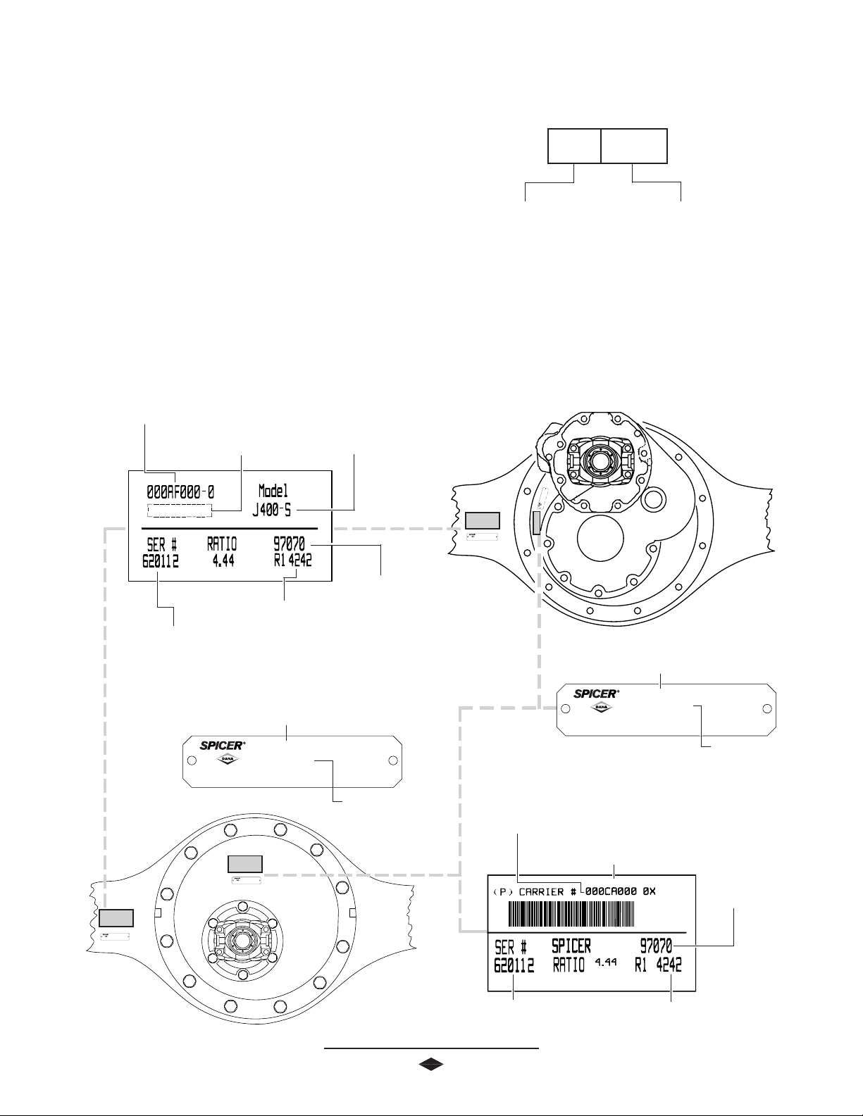
All axle assemblies are identified with two tags. One located
on the differential carrier, and the other located on the right
hand side of the axle housing. Two types of tags may be found
on the axle, an aluminum tag that is riveted on the assembly or
a coated mylar tag.
JULIAN DJULIAN D
JULIAN D
JULIAN DJULIAN D
MODEL YEARMODEL YEAR
MODEL YEAR
MODEL YEARMODEL YEAR
AXLE IDENTIFICA TION
AA
TE CODETE CODE
A
TE CODE
AA
TE CODETE CODE
99
7 17 1
9
7 1
99
7 17 1
77
7
77
00
0
00
DD
AA
Y OF YEARY OF YEAR
D
A
Y OF YEAR
DD
AA
Y OF YEARY OF YEAR
The aluminum axle assembly tag contains the following items:
serial number, according to the julian date, Dana part number,
and the model. The mylar axle assembly tag contains the
following items: Dana part number, julian date code, axle
model, and ratio. Optional items include customer part
number, line set number, and the last six digits of the vehicle
serial number.
DD
ANA PANA P
ARAR
D
ANA P
DD
ANA PANA P
NUMBERNUMBER
NUMBER
NUMBERNUMBER
LASLAS
LAS
LASLAS
VEHICLE SERIAL NUMBERVEHICLE SERIAL NUMBER
VEHICLE SERIAL NUMBER
VEHICLE SERIAL NUMBERVEHICLE SERIAL NUMBER
(OPTIONAL)(OPTIONAL)
(OPTIONAL)
(OPTIONAL)(OPTIONAL)
TT
AR
T
ARAR
TT
CUSCUS
CUS
CUSCUS
PP
P
PP
(OPTIONAL)(OPTIONAL)
(OPTIONAL)
(OPTIONAL)(OPTIONAL)
T SIX DIGITS OFT SIX DIGITS OF
T SIX DIGITS OF
T SIX DIGITS OFT SIX DIGITS OF
Axle Assembly Tags
TT
OMEROMER
T
OMER
TT
OMEROMER
ARAR
T NUMBERT NUMBER
AR
T NUMBER
ARAR
T NUMBERT NUMBER
SERIAL NUMBERSERIAL NUMBER
SERIAL NUMBER
SERIAL NUMBERSERIAL NUMBER
LINE SETLINE SET
LINE SET
LINE SETLINE SET
NUMBERNUMBER
NUMBER
NUMBERNUMBER
(OPTIONAL)(OPTIONAL)
(OPTIONAL)
(OPTIONAL)(OPTIONAL)
000000
000AF000-0
MODELMODEL
MODEL
MODELMODEL
JULIAN DJULIAN D
JULIAN D
JULIAN DJULIAN D
CODECODE
CODE
CODECODE
MODELSN
DD
ANA PANA P
D
ANA P
DD
ANA PANA P
NUMBERNUMBER
NUMBER
NUMBERNUMBER
J400-S
ARAR
AR
ARAR
AA
TETE
A
TE
AA
TETE
TT
T
TT
The aluminum differential carrier tag contains the following
items: serial number, according to the julian date code, the Dana
part number, and ratio. The mylar differential carrier tag
contains the following: Dana part number, julian date code, and
ratio. Optional items include customer part number, line set
number, and the last six digits of the vehicle serial number.
SERIAL NUMBERSERIAL NUMBER
SERIAL NUMBER
SERIAL NUMBERSERIAL NUMBER
SN 00000
000CA000-0X
RATIO
4.44
DD
ANA PANA P
ARAR
AR
ARAR
TT
T
TT
DD
ANA PANA P
D
ANA P
DD
ANA PANA P
NUMBERNUMBER
NUMBER
NUMBERNUMBER
ARAR
AR
ARAR
TT
T
TT
Carrier Tags
CUSCUS
TT
OMEROMER
CUS
T
OMER
CUSCUS
TT
OMEROMER
PP
ARAR
T NUMBERT NUMBER
P
AR
T NUMBER
PP
ARAR
T NUMBERT NUMBER
(OPTIONAL)(OPTIONAL)
(OPTIONAL)
(OPTIONAL)(OPTIONAL)
D
ANA P
DD
ANA PANA P
NUMBERNUMBER
NUMBER
NUMBERNUMBER
JULIAN DJULIAN D
JULIAN D
JULIAN DJULIAN D
LASLAS
T SIX DIGITS OFT SIX DIGITS OF
LAS
T SIX DIGITS OF
LASLAS
T SIX DIGITS OFT SIX DIGITS OF
VEHICLE SERIAL NUMBERVEHICLE SERIAL NUMBER
VEHICLE SERIAL NUMBER
VEHICLE SERIAL NUMBERVEHICLE SERIAL NUMBER
(OPTIONAL)(OPTIONAL)
(OPTIONAL)
1
(OPTIONAL)(OPTIONAL)
LINE SETLINE SET
LINE SET
LINE SETLINE SET
NUMBERNUMBER
NUMBER
NUMBERNUMBER
(OPTIONAL)(OPTIONAL)
(OPTIONAL)
(OPTIONAL)(OPTIONAL)
AA
TETE
A
TE
AA
TETE
CODECODE
CODE
CODECODE
Page 4
MODEL IDENTIFICA TION NUMBERING SYSTEM
Load Carrying Capacity
(340 = 34,000 Lbs.)
(380 = 38,000 Lbs.)
(400 = 40,000 Lbs.)
(440 = 44,000 Lbs.)
(460 = 46,000 Lbs.)
J 400J 400
J 400
J 400J 400
Family
(J,W)
S N S N
S N
S N S N
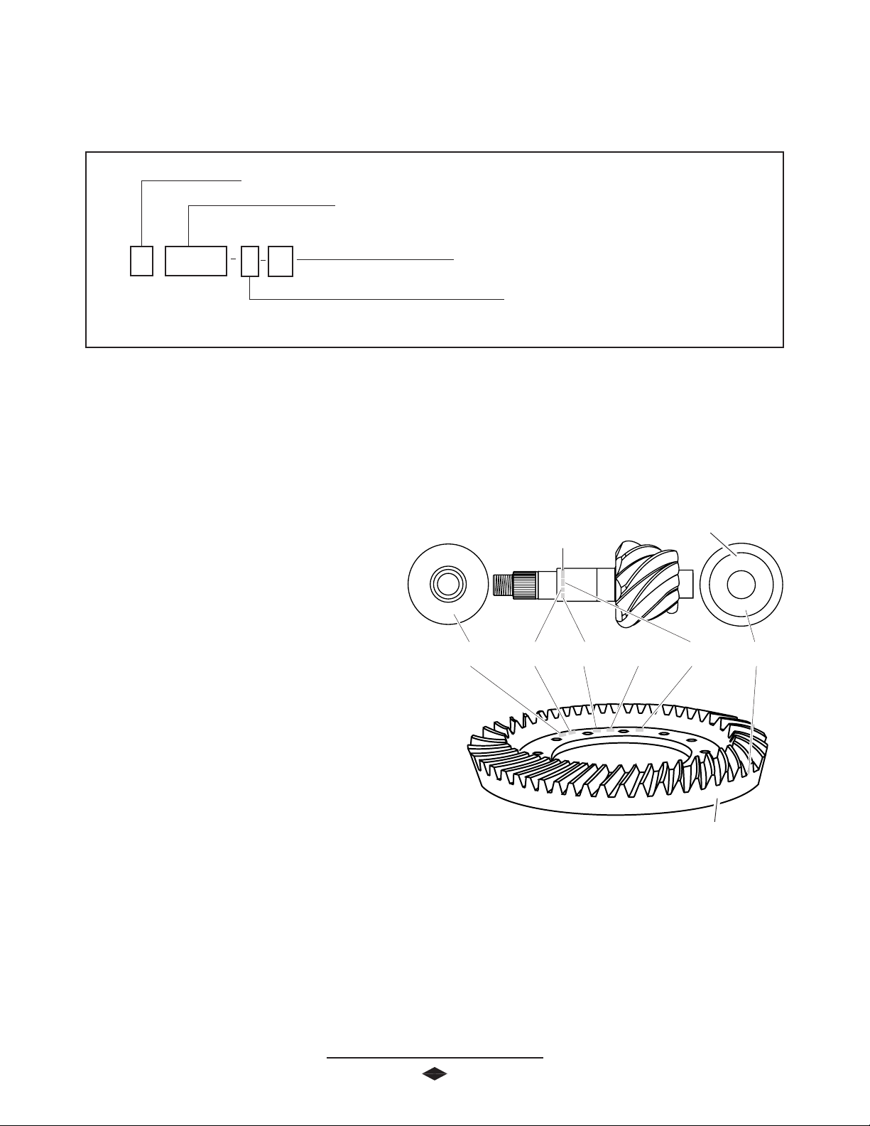
GEAR SET IDENTIFICA TION
Manufacturer's Date- Date gear set was made.
Spicer Trademark- Dana Diamond and location of manufac-
turing facility.
047GP000- Part number of pinion. (TYPICAL)
047GR000- Part number of ring gear. (TYPICAL)
Options
(N= No-SPIN® option)
Gearing Type
(S= Single Reduction)
TRADEMARK
41-11
SPICER
* No-SPIN® is a registered trademark of Tractech
PINION
ETCH
+15
472
Tooth Combination(i.e. 41-11)- Indicates the pinion has 11
teeth and the ring gear has 41 teeth which results in a 3:73:1
ratio.
Matched Set Number- Spicer ring gears and pinions are
manufactured as matched sets. Both ring gear and pinion are
marked with a corresponding number (i.e. 472), which
identifies them as a matched set.
A gear set that does not have the same match set numbers
should not be run together. If either ring gear or pinion
require replacement,
a new matched set must be used.
Backlash Etch- Indicates backlash setting for assembly.
Pinion Etch- Indicator for proper pinion position shim stack
up. See Pinion Position Section.
2
TOOTH
COMBINATION
PART
NUMBER
HEAT
CODE
SPICER
TRADEMARK
MFG.
DATE
L10
BACKLASH
ETCH
MATCHED
SET NUMBER
472
Page 5
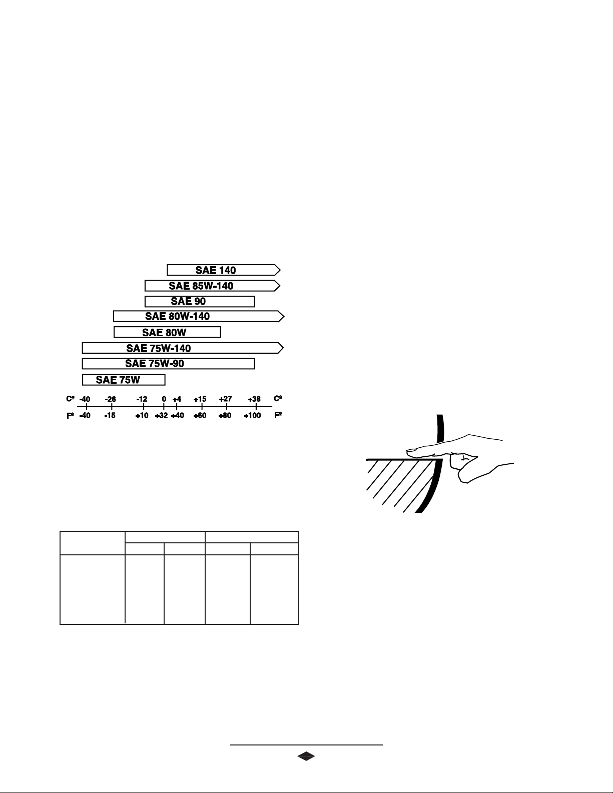
AXLE LUBRICANT RECOMMENDA TIONS
To ensure proper lubrication and operating temperature,
correct lubricants and lubricant levels must be obtained.
RECOMMENDED LUBRICANTS
Mineral or Synthetic based hypoid gear lubricants that meet
or exceed military specification MIL-L-2105D, and API service
classification GL-5, are the minimum requirements for use in
Spicer medium and heavy duty drive axles.
The table below indicates which SAE viscosities are recommended for various temperature ranges the vehicle will
encounter.
SUBMERSION OR DEEP WATER FORDING
In the event the axle assembly should become
submerged in water, particularly if over the vent or breather, it
is recommended that the lubricant be drained and all parts be
inspected for water damage and/or contamination. Reassemble the carrier to the housing and refill with specifed gear
lubricant.
AFTER OVERHAUL OR CHANGE INTERVALS
Fill the axle assembly to the bottom of housing fill hole as
shown in the illustration below. It is recommended that
following an overhaul, each side of the axle be jacked up
seperately to approximately six inches and held into position
for one minute. This procedure will allow adequate lubricant
to flow into the wheel ends and help eliminate the possibility
of premature damage to wheel bearings and seals. Lower the
vehicle to the floor and allow ten minutes for lube to return to
normal level. Check and refill assembly to bottom of fill hole to
replace the lubricant that was directed into the wheel ends.
Ambient Air Temperature
SERVICE
Recommended lubricant change intervals are dependent on
the application and operating environment. The following
chart should be used to establish proper change intervals.
PETROLEUM BASED PETROLEUM BASED
PETROLEUM BASED
APPLICAAPPLICA
APPLICA
APPLICAAPPLICA
On Highway 100,000 1 Year 250,000 3 Year
* Severe Service
and 50,000 1 Year 100,000 1 Year
On-Off Highway
PETROLEUM BASED PETROLEUM BASED
TIONTION
TION
TIONTION
MILES INTER MILES INTER
MILES INTER
MILES INTER MILES INTER
SYNTHETIC BASED** SYNTHETIC BASED**
SYNTHETIC BASED**
SYNTHETIC BASED** SYNTHETIC BASED**
VV
AL MILES INTERAL MILES INTER
V
AL MILES INTER
VV
AL MILES INTERAL MILES INTER
VV
ALAL
V
AL
VV
ALAL
* Severe service includes any applications operating at
or near maximum GVW or GCW ratings. This
includes normally wet or dusty environments, or
consistent heavy load and low speed applications.
** Includes Semi-Synthetic blends that meet
MIL-L-2105D specifications.
NOTE: Lubricant close enough to the bottom of the fill hole to be seen or touched
is not sufficient. Lubricant must be level with the fill hole.
3
Page 6
GENERAL PRECAUTIONS
READ THIS SECTION BEFORE STARTING
GENERAL AXLE DESCRIPTION
IMPORTANT
ANY SERVICE PROCEDURES
This manual covers maintenance and rebuild procedures for the
Spicer J340-S, J380-S, J400-S, W440-S and W460-S rear
drive tandem axle assemblies.
Accordingly, anyone who uses a service procedure or tool
different than shown must insure that their safety, and the
vehicle's safety, will not be jeopardized by the service method
selected.
The Spicer heavy duty single reduction rear drive axle is a full
floating axle assembly, with a hypoid gear carrier assembly,
END YOKES AND FLANGES
using a High Strength Low Alloy (HSLA) steel axle housing.
The hypoid pinion is straddle mounted with two tapered roller
bearings behind the pinion teeth for thrust and radial loads. A
pilot bearing is located on the nose of the pinion for radial
load. The differential itself uses four precision forged pinion
mate gears, a forged cross, and precision forged side gears.
bearing bores or misalign yoke lugs and result in early failures
of journal needle bearings or other driveline components.
Serious damage can also be done internally to the ring and
pinion set or pinion bearings by hammering on external parts.
End yokes or companion flanges should be removed or
installed using the recommended methods outlined in this
manual.
Safety glasses should be worn
at all times when assembling or
disassembling axles.
CLEANLINESS
Axle components should be steam cleaned prior to removal
from the vehicle. Dirt is abrasive and will cause premature wear
of otherwise serviceable parts. Service personnel should use a
wash tank for thorough cleaning of parts just prior to assembly.
CAUTION: Hammering on end yokes can close in the
SAFETY PRECAUTIONS
Proper service and repair of vehicle components is important
to the safe and reliable operation of all motor vehicles. This
applies particularly to driving axles such as the ones described
in this manual. The procedures recommended and described
in this manual are tested, effective methods for performing
service operations. Follow each procedure closely, making use
of both the text and illustrations. Some of these service
procedures show the use of certain tools designed specifically
for the operation being performed. They are shown as a
preferred means of performing the operation. It is not practical
to anticipate and advise the service trade of all possible
alternative methods, and of all possible hazardous consequences that could occur.
4
CAUTION
BRAKE LININGS CONTAIN NON-ASBESTOS FIBERS
BRAKE LININGS CONTAIN NON-ASBESTOS FIBERS
BREATHING BRAKE DUST MAY BE HAZARDOUS TO YOUR HEALTH AND
MAY CAUSE SERIOUS RESPIRATORY OR OTHER BODILY HARM.
AVOID CREATING DUST
DO NOT REMOVE BRAKE DRUM WITHOUT PROPER PROTECTIVE EQUIPMENT.
DO NOT WORK ON LININGS WITHOUT PROPER PROTECTIVE EQUIPMENT.
DO NOT REPLACE LININGS WITHOUT PROPER PROTECTIVE EQUIPMENT.
DO NOT ATTEMPT TO SAND, GRIND, CHISEL, FILE, HAMMER OR ALTER BRAKE
LININGS IN ANY MANNER WITHOUT PROPER PROTECTIVE EQUIPMENT.
FOLLOW 0.S.H.A. STANDARDS FOR PROPER PROTECTIVE DEVICES TO BE USED
WHEN WORKING WITH BRAKE MATERIALS.
Page 7
Air Shift Cylinder
Retainer Clip
Retainer Spring
Idler Gear Shaft
Shift Fork Shaft
(30-38 Lb-Ft)
(41-51 N-m)
Idler Gear Front Bearing Cone
Idler Gear Front Bearing Cup
Idler Gear
Idler Gear Bearing Spacer (Selective)
Shift Fork
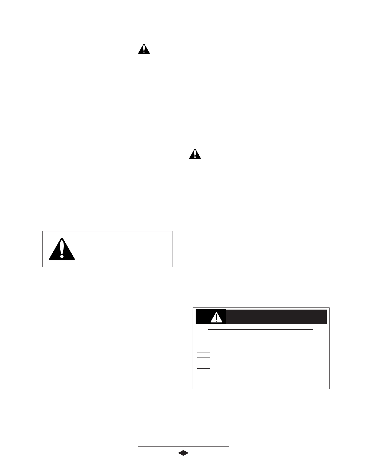
POWER DIVIDER COMPONENTS
IMPORTANT: Torque
specifications, shown on illustration,
apply only to J Model. See Page 3334 for W Model torque specifications.
Idler Gear Front Bearing Cup
Idler Gear Front Bearing Cone
Intermediate Housing
Air Shift Cylinder Bolt
(30-40 Lb-Ft)
(41-55 N-m)
Idler Shaft Nut
(500-600 Lb-Ft)
(678-813 N-m)
Intermediate Housing Bolt
(75-90 Lb-Ft)
(102-122 N-m)
Drive Gear Bearing Cup
Drive Gear Bearing Cone
Input Drive Gear
Inter-Axle Differential Bearing Cone
Inter-Axle Differential Bearing Cup
Shift Collar
Spiral Snap Ring
Inter-Axle Differential Rear Bearing
Inter-Axle Differential Case Assembly
Input Bearing Cone
Input Bearing Cup
Shim (Selective)
Inter-Axle Differential Cover
Inter-Axle Differential Cover Bolt
(75-90 Lb-Ft)
(102-122 N-m)
Fill Plug
Pinion Oil Seal
End Yoke Assembly
Flanged Hex Nut
(900-1,200 Lb-Ft)
(1,220-1,627N-m)
5
Page 8
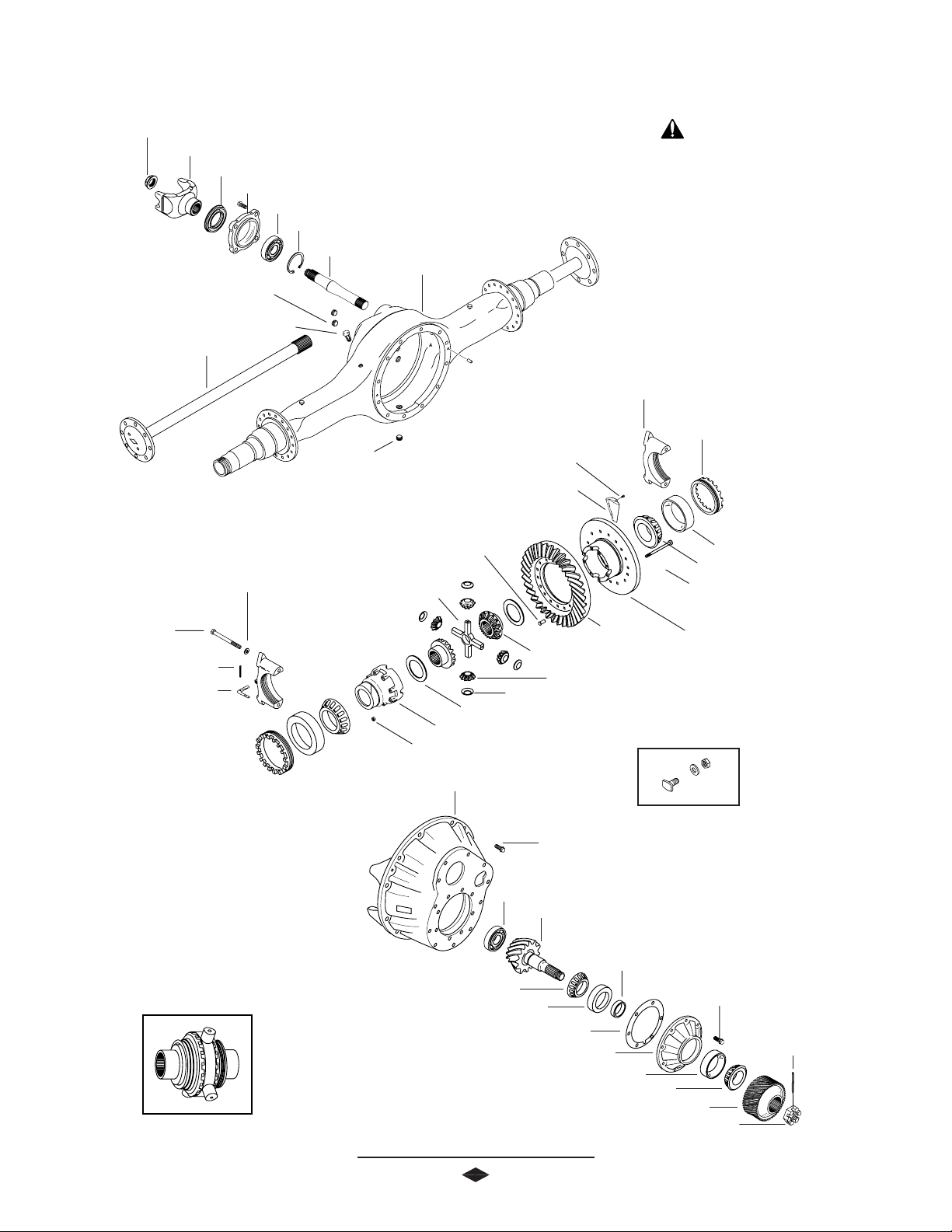
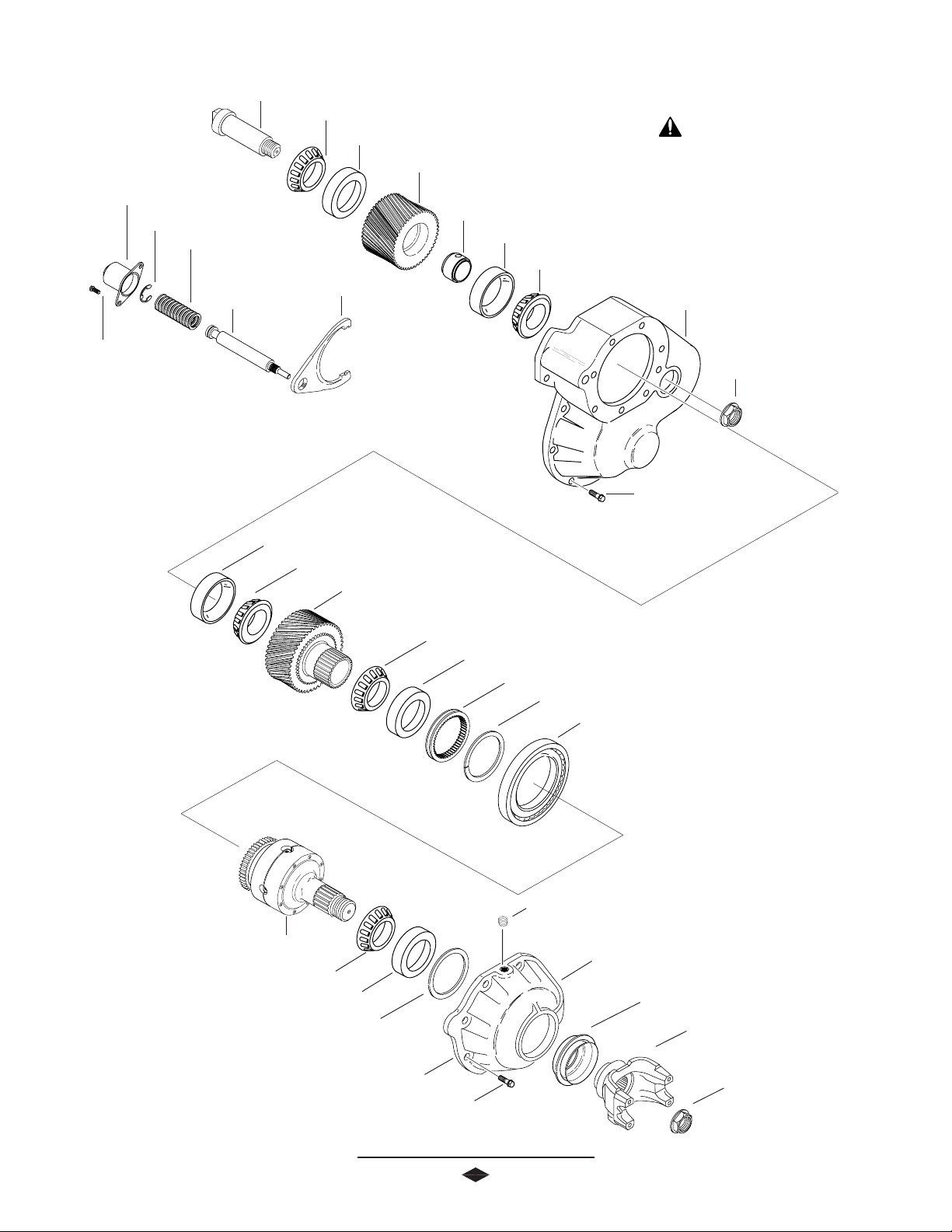
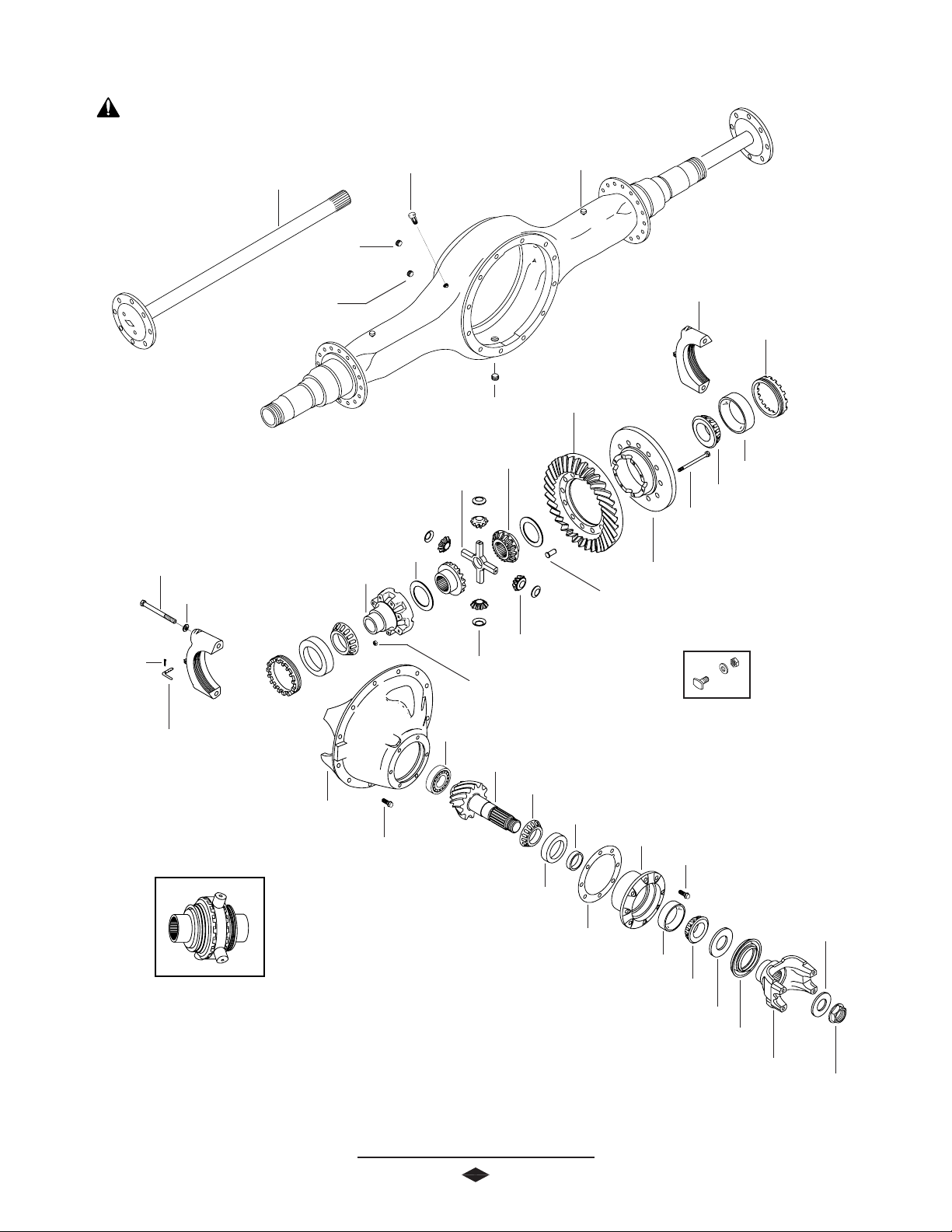
FORW ARD REAR AXLE COMPONENTS
Flanged Hex Nut
(500-600 Lb-Ft)
(680-816 N-m)
Output Yoke Assembly
Output Oil Seal
Bearing Retainer
Output Shaft Bearing
Snap Ring
Output Shaft
Fill Plug
(35-45 Lb-Ft)
(47-61 N-m)
Vent Plug
Axle Shaft
Housing
IMPORTANT: Torque
specifications, shown on illustration,
apply only to J Model. See Page 3334 for W Model torque specifications.
Differential Bearing Cap
Differential Bearing
Cap Washer
Differential Bearing Cap Bolt
(295-340 Lb-Ft)
(397-460 N-m)
Cotter Pin
Adjusting Ring Lock
Magnetic Drain Plug
(35-45 Lb-Ft)
(47-61 N-m)
Ring Gear Rivet
(45-50 tons)
(41-45 metric tonnes)
Differential Cross Shaft
Differential Case Nut
Oil Scoop Bolt
(7-9 Lb-Ft)
(10-12 N-m)
Oil Scoop
Differential Side Gear
Differential Pinion Mate
Differential Gear Thrust Washer
Differential Case Half
Carrier Housing
Carrier Mounting Bolt
(240-260 Lb-Ft)
(325-352 N-m)
Pinion Pilot Bearing
Pinion
Adjusting Ring
Differential Bearing Cup
Differential Bearing Cone
Differential Case Bolt
(115-135 Lb-Ft)
Ring Gear
Differential Pinion Mate Thrust Washer
(156-183 N-m)
Differential Case Flange Half
Ring Gear Bolt Kit
(300-320 Lb-Ft)
(407-433 N-m)
No-Spin® Differential
Inner Pinion Bearing Cone
Inner Pinion Bearing Cup
Pinion Position Shim(s)
Pinion Bearing Cage
Outer Pinion Bearing Cup
6
Bearing Preload Spacer (Selective)
Pinion Bearing Cage Bolt
(115-135 Lb-Ft)
(156-183 N-m)
Roll Pin
Outer Pinion Bearing Cone
Pinion Driven Gear
Castillated Pinion Nut
*(600 Lb-Ft Min.)
(816 N-m Min.)
Page 9
IMPORTANT: Torque
specifications, shown on illustration,
apply only to J Model. See Page 3334 for W Model torque specifications.
Axle Shaft
Temperature Sensor Plug
Pinion-Up Components
Differential Bearing Cap Bolt
(295-340 Lb-Ft)
(397-460 N-m)
Differential Bearing Cap Washer
Cotter Pin
Adjusting Ring Lock
Differential Case Cap Half
Vent Plug
Fill Plug
(35-45 Lb-Ft)
(47-61 N-m)
(35-45 Lb-Ft)
(47-61 N-m)
Differential Cross Shaft
Differential Gear Thrust Washer
Magnetic Drain Plug
(35-45 Lb-Ft)
(47-61 N-m)
Differential Side Gear
Differential Pinion Mate
Differential Pinion MateThrust Washer
Differential Case Nut
Pinion Pilot Bearing
REAR REAR AXLE COMPONENTS
Housing
Differential Bearing Cap
Adjusting Ring
Ring Gear
Differential Bearing Cup
Differential Bearing Cone
Differential Case Bolt
(115-135 Lb-Ft)
(156-183 N-m)
Differential Case Flange Half
Ring Gear Rivet
(45-50 tons)
(41-45 metric tonnes)
Ring Gear Bolt Kit
(300-320 Lb-Ft)
(407-433 N-m)
No-Spin® Differential
Carrier Housing
Carrier Mounting Bolt
(240-260 Lb-Ft)
(325-352 N-m)
Pinion
Inner Pinion Bearing Cone
Inner Pinion Bearing Cup
Pinion Position Shim(s)
Outer Pinion Bearing Cup
7
Pinion Bearing Spacer (Selective)
Pinion Bearing Cage
Pinion Bearing Cage Bolt
(160-180 Lb-Ft)
(217-244 N-m)
Washer
Outer Pinion Bearing Cone
Bearing Preload Spacer
Pinion Oil Seal
End Yoke Assembly
Flanged Hex Nut
(900-1,200 Lb-Ft)
(1,220-1,627 N-m)
Page 10
REMOV AL OF DIFFERENTIAL CARRIER FROM AXLE HOUSING
FORWARD REAR CARRIER
(WITH POWER DIVIDER)
NOTE: Steam clean axle assembly.
1. Block wheels.
2. Remove axle housing drain plug and drain lubricant.
3. Disconnect drive shafts from input and output shaft
end yokes.
NOTE: If end yoke and/or seal is to be replaced, loosen
flanged hex nut at this time.
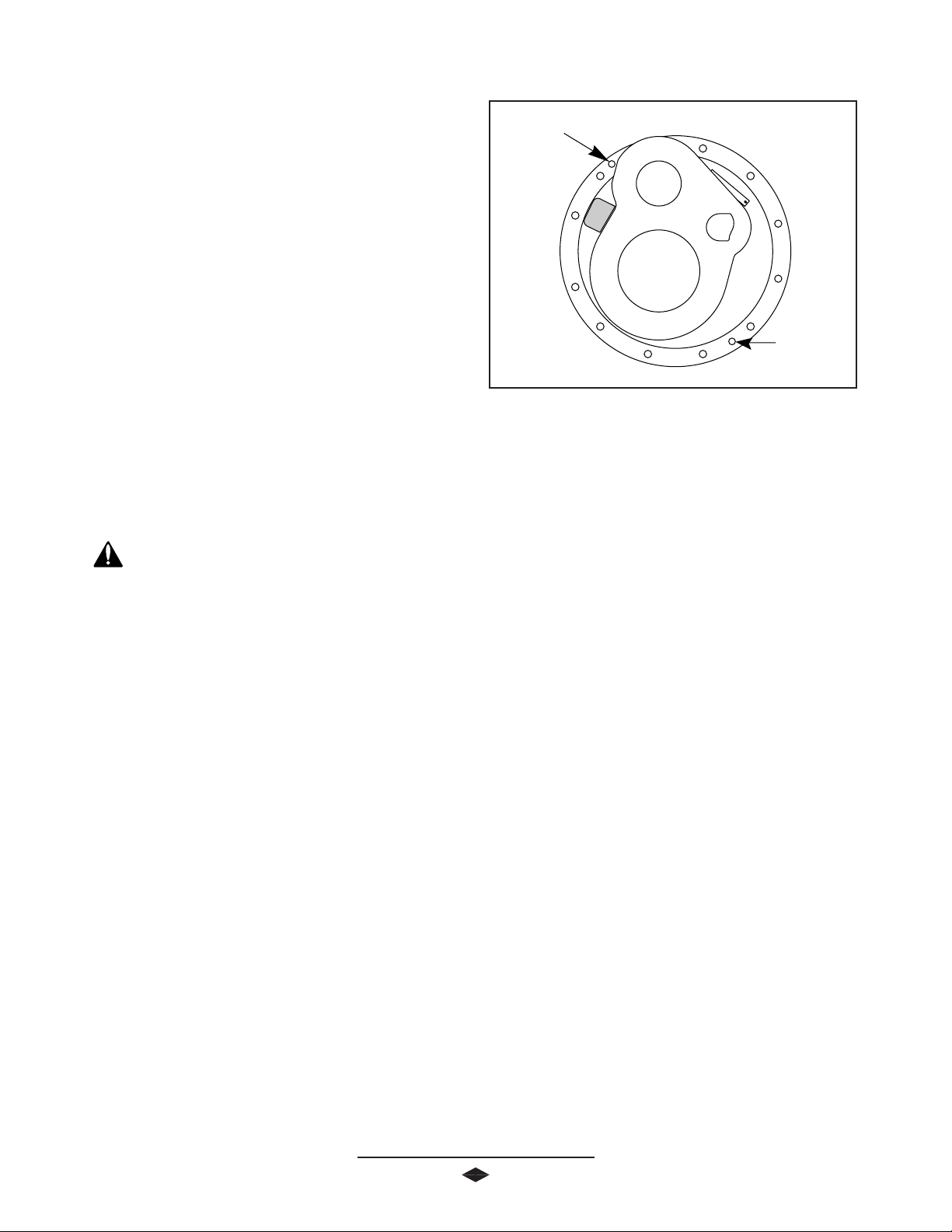
4. Remove axle shaft flange nuts.
Threaded
Removal Hole
FF
F
FF
igurigur
igur
igurigur
e 1e 1
e 1
e 1e 1
Threaded
Removal Hole
5. Hold a large brass drift or a brass hammer against
the center of the axle shaft flange. Strike the drift
with sharp blows from a large hammer or sledge
until the axle shaft separates from the hub.
CAUTION: Do not strike the flange directly with a steel
hammer or sledge. This may crack and splinter material,
possibly causing serious or fatal injury. Do not pry or chisel
axle flange away from hub or damage to sealing surfaces
could occur.
6. Remove axle shafts.
7. Disconnect air line from power divider control.
8. Remove output shaft bearing retainer bolts. Use a
soft hammer to loosen bearing retainer from axle
housing. Remove bearing cage and output shaft
from axle housing.
9. Support the differential carrier assembly on a roller
jack. Secure as necessary to prevent it from
falling off the jack when removed from the housing.
10 . Use a breaker bar to loosen the differential carrier-
to-housing mounting bolts. Remove all bolts except
top two. These two bolts will prevent the carrier
assembly from falling.
NOTE: Removal holes are provided in the areas shown in the
illustration. See Figure 1.
certain carrier is balanced properly on jack, and
remove top two carrier-to-housing mounting bolts.
Remove differential carrier assembly from the axle
housing.
12 . Remove carrier assembly from under the vehicle.
13 . Mount carrier assembly in a suitable rebuild stand.
(Refer to Recommended Service Tools, Pgs. 35-36).
Differential Carrier Removal Complete
REAR REAR CARRIER
NOTE: Steam clean axle assembly.
1. Block wheels.
2. Remove axle housing drain plug and drain lubricant.
3. Disconnect drive shaft at rear U-joint.
NOTE: If end yoke and/or seal is to be replaced, loosen
flanged hex nut at this time.
4. Remove axle shaft flange nuts.
5. Hold a large brass drift or a brass hammer against
the center of the axle shaft flange. Strike the drift
with sharp blows from a large hammer or sledge
until the axle shaft separates from the hub.
11. Separate differential carrier from the housing. Be
6. Remove axle shafts.
8
Page 11
REMOV AL OF DIFFERENTIAL CARRIER FROM AXLE HOUSING
7. Support the differential carrier assembly on a roller jack.
Secure as necessary to prevent it from falling off the jack
when removed from the housing.
8. Use a breaker bar to loosen the differential carrier-
to-housing mounting bolts. Remove all bolts except
top two. These two bolts will prevent the carrier
assembly from falling.
CAUTION: Do not strike the flange directly with a steel
hammer or sledge. This may crack and splinter material,
possibly causing serious or fatal injury. Do not pry or chisel
axle flange away from hub as damage to sealing surfaces
could occur.
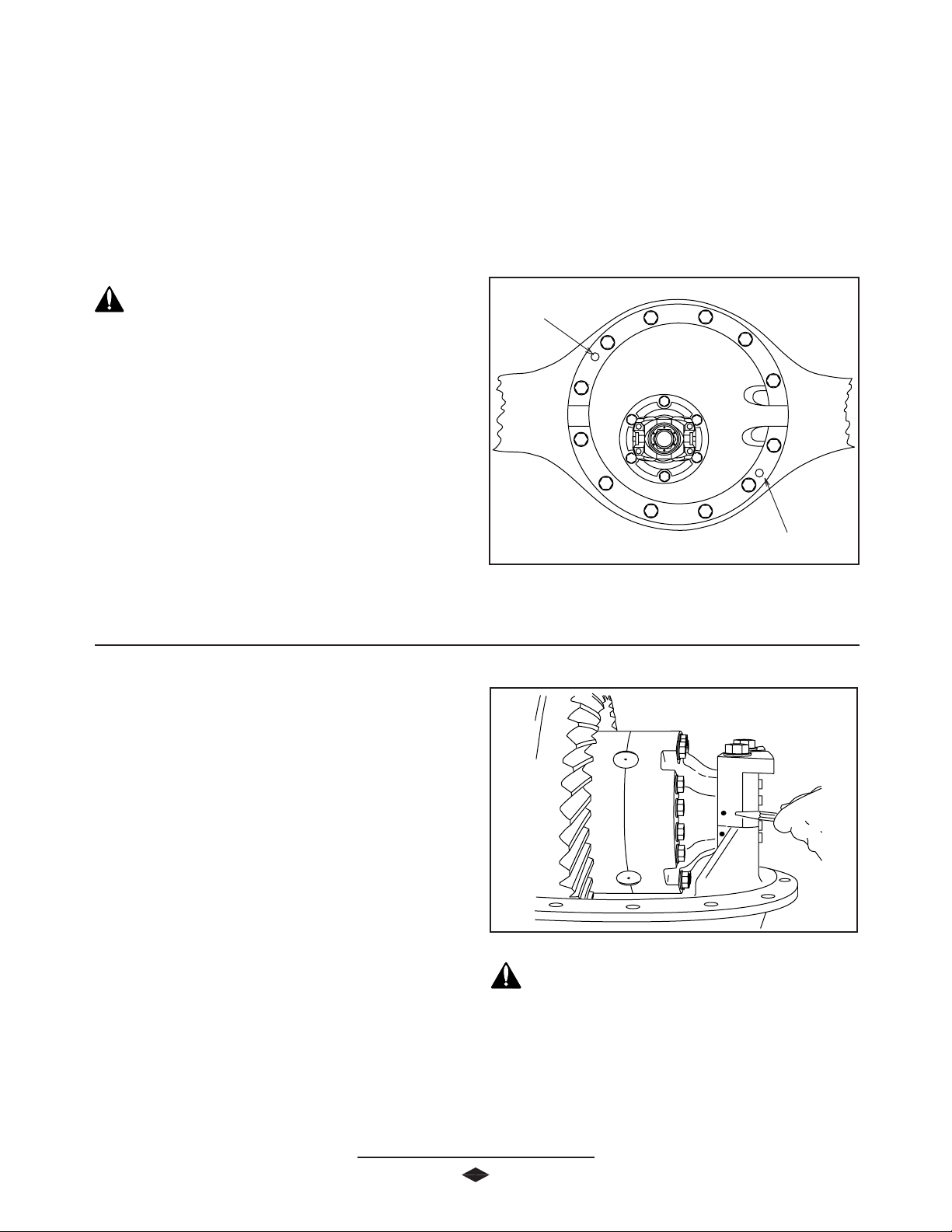
NOTE: Removal holes are provided in the areas shown in the
illustration See Figure 1 & 2.
9. Install two 1/2”-13 bolts into threaded holes provided
in carrier housing flange. See Figure 2. Turn puller bolts
in to break carrier away from housing. Be certain carrier is
balanced properly on the jack, and remove top two
carrrier-to-housing mounting bolts. Remove differential
carrier assembly from the axle housing.
10 . Remove carrier assembly from under the vehicle.
11 . Mount carrier assembly in a suitable rebuild stand. (Re-
fer to Recommended Service Tools, Pgs. 35-36)
Differential Carrier Removal Complete
Threaded
Removal
Hole
Threaded
Removal
Hole
FF
igurigur
e 2e 2
F
igur
e 2
FF
igurigur
e 2e 2
REMOV AL OF DIFFERENTIAL FROM CARRIER
NOTE: The following service procedures apply to both the
forward rear and rear rear axles, unless otherwise noted.
1. Remove adjusting ring locks from bearing caps.
2. Match mark one differential bearing cap and leg of carrrier
with center punch or chisel for use during reassembly.
See Figure 3.
. Loosen four bearing cap retaining bolts.
3
4. Loosen adjusting ring, relieving bearing preload.
5. Remove four bearing cap retainer washers and bolts.
6. Remove bearing caps.
7. Remove adjusting rings and bearing cups.
NOTE: The ring gear side of the subassembly must be tipped
up for the ring gear to clear pinion roller bearing retainer.
8. Carefully lift the ring gear and differential subassembly
out of the carrier.
9
FF
igurigur
e 3e 3
F
igur
e 3
FF
igurigur
e 3e 3
CAUTION: Use care not to damage the ring gear and
pinion. If either ring gear or pinion show signs of damage,
they must be replaced as a matched set.
Removal of Differential Complete
Page 12
DIFFERENTIAL DISASSEMBL Y
IMPORTANT: Torque
specifications, shown on illustration,
apply only to J Model. See Page 3334 for W Model torque specifications.
Differential Pinion Mate Thrust Washer
Differential Bearing Cap Bolt
(295-340 Lb-Ft)
(370-435 N-m)
Cotter Pin
Adjusting Ring
Lock
Differential Bearing Cap
Differential Side Gear
Differential Pinion Mate
Differential Bearing
Cap Washer
Differential Bearing Cone
Differential Bearing Cup
Oil Scoop Bolt
(7-9Lb-Ft)
(9-12 N-m)
Oil Scoop
Differential Cross Shaft
Differential Gear Thrust Washer
Differential Case Cap Half
Differential Case Nut
(115-135 Lb-Ft)
(156-183 N-m)
Adjusting Ring
Differential Case Bolt
(115-135 Lb-Ft)
(156-183 N-m)
Differential Case Flange Half
Ring Gear
Ring Gear Rivet
(40-45 tons)
(41-50 metric tonnes)
Ring Gear Bolt Kit
(300-320 Lb-Ft)
(406-434 N-m)
(Optional)
FF
igurigur
e 4e 4
F
igur
e 4
FF
igurigur
e 4e 4
1. Match mark differential case halves with punch or chisel
for correct alignment during reassembly. See Figure 4.
2. Remove differential case bolts and lift off the differential
case half.
3. Remove thrust washer and differential side gear.
4. Lift out cross shaft, pinion mates, and thrust washer.
10
FF
igurigur
e 5e 5
F
igur
e 5
FF
igurigur
e 5e 5
5. Remove second differential side gear and thrust washer.
6. If differential side bearings are to be replaced, remove old
bearings using suitable puller. See Figure 5.
NOTE: Inspect all parts, including the machined surfaces of the
case itself.
Page 13

DIFFERENTIAL DISASSEMBL Y
IMPORTANT: If any gears are to be replaced, they must be
replaced in sets. Inspect thrust washers for scoring and
excessive wear. Replace all worn or damaged parts.
7. When it is necessary to remove ring gear from differential
case, carefully center punch each rivet head. Use a 9/16"
drill bit on the J model carrier rivets and a 11/16” drill bit
for the W model carrier rivets. Drill through the rivet
heads to a depth as shown through rivet heads. See
Figure 6.
CORRECT PROCEDURE
Case
Ring Gear
8. Next, use a round type punch to drive out the remaining
portion of the rivet.
CAUTION: Always use a soft hammer or H.D. plastic
head hammer to strike punch.
NOTE: Do not use a chisel to remove rivet heads, damage to
differential case may result. See Figure 7.
Differential Disassembly Complete
INCORRECT PROCEDURE
Case
Ring Gear
FF
igurigur
F
igur
FF
igurigur
e 6e 6
e 6
e 6e 6
FF
igurigur
F
igur
FF
igurigur
e 7e 7
e 7
e 7e 7
11
Page 14

INTER-AXLE DIFFERENTIAL DISASSEMBL Y
Spiral Snap Ring
Inter-Axle Differential Rear Bearing
Inter-Axle Differential Case
Assembly
Input Bearing Cone
Input Bearing Cup
Shim (Selective)
Inter-Axle Differential
Cover Bolt
(75-90 Lb-Ft)
(102-122N-m)
1. Remove the inter-axle shift cylinder assembly, compress
spring and remove retainer clip. Remove spring.
Fill Plug
Inter-Axle Differential Cover
Pinion Oil Seal
End Yoke
Assembly
Flanged Hex Nut
(900-1,200 Lb-Ft)
(1,220-1,627N-m)
2. Screw shift fork shaft out and remove from differential
carrier.
3. Remove inter-axle differential cover bolts
NOTE: One bolt is larger than the others and must be
replaced in the same postion.
4. Lift inter-axle differential assembly from power
divider case. Use of an overhead crane or hoist is
recommended.
5. Remove input flanged hex nut.
NOTE: Use of torque multiplier is recommended as torque
specification on the input nut is 900-1,200 Lb-Ft (1,2201,627 N-m).
6. Remove input yoke using suitable puller. See Figure 8.
7. Lift off inter-axle differential cover housing.
8. Remove bearing cup and shims from inter-axle differential
housing. Retain shims for possible use during reassembly
9. To remove spiral snap ring, use a small bladed screwdriver. Insert tip into slot of snap ring and lift away from
case. Apply pressure under snap ring and lift away from
case. Apply pressure under snap ring and rotate around
case until snap ring is free.
FF
igurigur
e 8e 8
F
igur
e 8
FF
igurigur
e 8e 8
10 . Remove ball bearing from inter-axle differential case using
a suitable puller.
11 . Match mark differential case halves to assure correct
alignment upon reassembly. Remove differential case
bolts and separate case halves.
12 . Remove pinion mates, front and rear side gears, cross
shaft, and thrust washers.
13 . If tapered roller bearing is to be replaced, remove
bearing using a suitable puller. See Figure 9.
Inter-axle Differential Disassembly Complete
12
Page 15

Idler Gear Shaft
Air Shift Cylinder
Retainer Clip
Retainer Spring
Idler Gear Front Bearing Cone
Idler Gear Front Bearing Cup
Idler Gear
Idler Gear Bearing Spacer (Selective)
INTERMEDIA TE CASE DISASSEMBLY
IMPORTANT: Torque
specifications, shown on illustration,
apply only to J Model. See Page 3334 for W Model torque specifications.
Idler Gear Front Bearing Cup
Idler Gear Front Bearing Cone
Inter-Axle Differential Case
Air Shift Cylinder Bolt
(30-40 Lb-Ft)
(41-55 N-m)
Shift Fork Shaft
(30-38 Lb-Ft)
(41-51 N-m)
Shift Fork
Inter-Axle Differential
Case Bolt
(75-90 Lb-Ft)
(102-122 N-m)
1. Remove intermediate case to carrier housing mounting
bolts. Lift intermediate case from differential carrier
housing using a hoist or overhead crane. If necessary, use
soft hammer to break seal between case and carrier.
Idler Shaft Nut
Drive Gear Bearing Cup
Drive Gear Bearing Cone
Input Drive Gear
Inter-Axle Differential Bearing Cone
Inter-Axle Differential Bearing Cup
Shift Collar
2. Lift clutch shift collar and shift fork from case. Inspect shift
fork for wear and misalignment.
3. Remove input gear assembly from intermediate case.
4. Remove bearing from input gear using a suitable puller.
See Figure 9.
FF
F
FF
igurigur
igur
igurigur
e 9e 9
e 9
e 9e 9
5. Turn gear over and remove opposite bearing.
6. Place intermediate case in soft jawed vise clamping on the
flats of the idler shaft. Remove idler shaft nut using a
torque multiplier wrench.
7. Remove intermediate case from vise. Tap idler shaft with a
soft hammer to free case and remove idler shaft.
8. Slide idler gear to large opening and remove idler gear,
bearings and bearing spacer for possible use during
reassembly.
Intermediate Case Disassembly Complete
13
Page 16

PINION DISASSEMBL Y
ID Tag
REAR REAR AXLE COMPONENTS
Carrier Housing
Pinion Pilot Bearing
IMPORTANT: Torque
specifications, shown on illustration,
apply only to J Model. See Page 3334 for W Model torque specifications.
Carrier Mounting Bolt
(240-260 Lb-Ft)
(325-352 N-m)
Pinion
Inner Pinion Bearing Cone
Inner Pinion Bearing Cup
Bearing Preload Spacer (Selective)
Pinion Bearing Cage
Pinion Bearing Cage Bolt
(115-135 Lb-Ft)
(156-183 N-m)
Washer
Pinion Nut
Pinion Seal
End Yoke
Used in place of
pinion driven gear,
castillated pinion
nut,and roll pin, that
are used on the
forward rear axle
carrier assembly.
1. Remove pinion bearing cage mounting bolts.
2. Remove pinion bearing cage and cage assembly from
carrier housing. If difficulty is encountered in removing
pinion assembly from carrier, place a brass drift on inner
end of pinion and tap lightly.
NOTE: Retain shims for possible use during reassembly.
3. Mount pinion assembly in a soft jawed vise or fixture,
holding yoke or pinion stationary. Remove roll pin, nut,
and washer.
4. Remove the end yoke or drive gear using a suitable press.
Pinion Position Shim(s)
Outer Pinion Bearing Cup
Outer Pinion Bearing Cone
Pinion Driven Gear
Castillated Pinion Nut
(600- Lb-Ft)Min.
(217 N-m) Min.
Roll Pin
6. Located between pinion bearings is a selective spacer,
used for pinion bearing preload. Retain this spacer for
possible use in reassembly.
7. Lift out the outer pinion bearing cone.
8. Remove inner pinion bearing cup, using a suitable
adapter and press or puller.
9. Remove roller bearing from end of pinion.
10 . Remove inner bearing cone from pinion.
Pinion Disassembly Complete
5. Remove pinion from cage assembly.
14
Page 17

Flanged Hex Nut
(500-600 Lb-Ft)
(678-813 N-m)
End Yoke Assembly (Output)
Output Shaft Bearing
Snap Ring
OUTPUT SHAFT DISASSEMBL Y
IMPORTANT: Torque
specifications, shown on illustration,
apply only to J Model. See Page 3334 for W Model torque specifications.
Output Shaft Oil Seal
Output Shaft Bearing Cage
Bolt
(30-40 Lb-Ft)
(41-55 N-m)
Output Shaft
1. Remove rear drive shaft.
2. Remove output shaft bearing cage assembly from forward
rear axle housing.
3. Mount output shaft in vise by clamping yoke in jaws of
vise.
4. Remove nut and yoke.
5. Use snap ring tool to remove snap ring from bearing
retainer.
6. Remove bearing and retainer from shaft.
7. Using a suitable sleeve to support bearing inner race,
press bearing from shaft.
8. Using suitable sleeve, press seal from retainer.
9. Clean and inspect all components. Replace all worn or
damaged components with genuine Spicer replacement
parts.
Output Shaft Disassembly Complete
15
Page 18

CLEANING AND INSPECTION
CLEANING
1. Parts should be cleaned with emulsion cleaners or
petroleum base cleaning solvent.
NOTE: Alkaline type solutions may cause damage to machined
surfaces and should be avoided.
2. Make sure interior of axle housing is clean prior to
reassembly.
3. Clean all gasket surfaces of old material.
DRYING
Use soft, clean, lintless towels or rags to dry components
after cleaning. Bearings should
not
be dried by spinning
with compressed air. This can damage mating surfaces
due to the lack of lubrication.
After drying, parts should be coated with a light coat of
lubricant or rust inhibitor to prevent damage from
corrosion. If parts are to be stored for a prolonged
period, they should be wrapped in wax paper.
GEARS
Inspect gears for excessive wear or damage. Replace
gears that are pitted, scored, broken, or worn.
SHAFTS
INSPECTION
Prior to reassembly, inspect parts for signs of excessive
wear or damage. Replacement of these parts can prevent
premature failure and costly downtime.
BEARINGS
Bearing surfaces should be inspected for pitting,
excessive wear, or overheating.
Inspect shafts for nicks or scoring.
SPLINES
Inspect all splines for excessive wear, distortion from
twisting, and cracking.
HOUSINGS
THRUST WASHERS
Inspect thrust washers for scoring and cracking.
Inspect housing for stripped threads and bending
16
fatigue.
Page 19

IMPORTANT: Torque
specifications, shown on illustration,
apply only to J Model. See Page 3334 for W Model torque specifications.
ID Tag
REAR REAR AXLE COMPONENTS
PINION ASSEMBLY
Carrier Housing
Carrier Mounting Bolt
(240-260 Lb-Ft)
(325-352 N-m)
Pinion Pilot Bearing
Pinion
Inner Pinion Bearing Cone
Inner Pinion Bearing Cup
Bearing Preload Spacer (Selective)
Pinion Bearing Cage
Pinion Bearing Cage Bolt
(115-135 Lb-Ft)
(156-183 N-m)
Washer
Pinion Nut
Pinion Seal
End Yoke
Used in place of
pinion driven gear,
castillated pinion
nut,and roll pin, that
are used on the
forward rear axle
carrier assembly.
1. Press inner pinion bearing cone onto the pinion.
2. Press roller bearing onto nose of pinion.
NOTE: Bearing must be installed with radius in bearing bore
toward pinion.
3. Stake roller bearing in nine places (See illustration
below), using a center punch or equivalent tool. This
operation will move gear shaft material outward into
bearing chamfer.
Pinion Position Shim(s)
Outer Pinion Bearing Cup
Outer Pinion Bearing Cone
Pinion Driven Gear
FF
igurigur
e 1e 1
00
F
igur
e 1
0
FF
igurigur
e 1e 1
00
Castillated Pinion Nut
(600- Lb-Ft)Min.
(217 N-m) Min.
bores See Figure 10. This is necessary for proper pinion
position.
NOTE: Make sure all cage bores are free of nicks, dirt, or any
other contaminants.
4. Install inner pinion bearing cup into pinion cage.
5. Install outer pinion bearing cup into pinion cage.
6. Use a feeler guage or shim stock .0015 in. (.0381mm) to
ensure bearing cups are completely seated in bearing
7. Press inner pinion bearing onto pinion stem.
8. Place selective preload spacer that was removed during
disassembly onto pinion.
9. Place pinion cage onto pinion inner bearing.
10 . Install outer pinion bearing cone onto pinion.
11 . Inspect rear rear carrier end yoke seal surface for grooves
caused by lip of seal. If grooves can be detected with
fingernail, it should be replaced.
12 . Install gear onto pinion of forward rear carrier. Place
assembly in a hydraulic press and seat gear on spline.
Torque castillated nut to 600 Lb-Ft Min. If hole in pinion
17
Page 20

PINION ASSEMBLY
does not align with slots in nut, tighten nut until they are
aligned. Do not install roll pin at this time.
On rear carriers, install end yoke onto pinion using yoke
installer service tool, (See Figure 11 and Recommended
Service Tools Pgs. 35-36), without seal to allow proper
setting of bearing preload. Tighten pinion nut to 9001200 Lb-Ft (1,220-1,627 N-m).
NOTE: Pinion cage should be rotated while tightening pinion
nut to seat and align the pinion bearings.
CAUTION: Wash spacer thoroughly of emery cuttings
before installing on pinion.
14 . After proper preload is achieved, install new roll pin into
forward carrier pinion. If roll pin cannot be installed,
tighten pinion nut until roll pin can be installed. Pinion
and cage assembly are now ready to be installed into the
carrier housing.
15 . After proper preload is achieved on rear carriers, remove
end yoke, and install new seal.
16 . Clean and dry threads on pinion.
17. Install pinion oil seal. (See Recommended Service Tools,
Pgs. 35-36)
18 . Install end yoke using yoke installer service tool. Coat
threads with Loctite #680 adhesive compound. See
Figure 11.
19 . Use torque multiplier and tighten flanged hex nut to 900-
1,200 Lb-Ft (1,220-1,627 N-m).
FF
igurigur
e 1e 1
11
F
igur
e 1
1
FF
igurigur
e 1e 1
11
12 . Measure torque to rotate with the torque wrench,
assemble pinion cage into the carrier housing and install
two mounting bolts to anchor the unit. Rotate pinion with
the torque wrench. See Figure 12. Torque measurement
will be taken during fourth revolution and must be
between 10-40 Lb-in (1.1-4.5 N-m) without pinion seal.
NOTE: When torque to rotate reading does not fall within
allowable limits, bearing preload can be increased by using a
thinner spacer or decreased by using a thicker spacer. A .001
in. (.025 mm) change in preload spacer thickness, changes
scale reading by approximately 10 lbs, .001 in. change in
preload spacer will change torque to rotate by approximately
30 Lb- in. This is only a guide, individual carriers may vary
slightly.
Pinion Assembly Complete
FF
igurigur
e 1e 1
22
F
igur
e 1
2
FF
igurigur
e 1e 1
22
The pinion bearing spacers are available in the following
thicknesses. Measure spacer with micrometers before
assembly to ensure correct thickness.
NOTE: Closer adjustment can be made by sanding next thicker
spacer to desired thickness using emery cloth on a flat
surface. Surfaces must be parallel to each other and square to
bore diameter.
18
J Model W Model
Inches MM Inches MM
.718 18.24 .893 22.68
.719 18.26 .894 22.71
Page 21

PINION ASSEMBLY
J Model W Model
Inches MM Inches MM
.720 18.29 .895 22.73
.721 18.31 .896 22.76
.722 18.34 .897 22.78
.723 18.36 .898 22.81
.724 18.39 .899 22.84
.725 18.41 .900 22.86
.726 18.44 .901 22.89
.727 18.47 .902 22.91
.728 18.49 .903 22.94
.729 18.52 .904 22.96
.730 18.54 .905 22.99
.731 18.57 .906 23.01
Ring gears and pinions are supplied in matched sets only.
Matching numbers on both the pinion and ring gear are etched
for verification. If a new gear set is being used, verify the
numbers of each pinion and ring gear before proceeding with
assembly. (See Gear Set Identification, Pg. 2)
J Model W Model
Inches MM Inches MM
.732 18.60 .907 23.04
.733 18.62 .908 23.06
.734 18.64 .909 23.09
.735 18.67 .910 23.11
.736 18.69 .911 23.14
.737 18.72 .916 23.27
.738 18.75
.739 18.77
.740 18.80
.741 18.82
.742 18.85
.745 18.92
PINION POSITION
3. Remove any burrs and wipe clean differential bearing
bore I.D.'s. Turn micrometer 90º to step plate. Install
assembled pinion setting gauge into bearing bores of
carrier housing until fully seated. Adjust micrometer so it
Pinion position is based on the nominal mounting distance
measured from the centerline of the ring gear to the nose of
the pinion. This dimension is controlled by selectively
shimming between the pinion cage assembly and the carrier
housing. The nominal dimension is 3.976 in. (100.990 mm).
NOTE: Be sure mounting surfaces and shims are free of burrs
and dirt prior to assembly as they will affect pinion position.
1. To establish the correct nominal dimension by using a
pinion setting gauge, install pinion and cage assembly
into the carrier housing without shims. Tighten pinion
cage bolts to correct torque specifications. (See Torque
Specification Chart, Pgs. 33-34) Failure to tighten
properly may result in incorrect gear adjustment.
2. Attach the step plate clamp assembly to the carrier
mounting flange. Locate step plate clamp screw over
center of pinion. Install step plate under clamp screw and
tighten to hold step plate securely in position.
NOTE: Be sure lugs on bottom of step plate straddle the
bearing staking indentions on end of pinion, or false reading
may occur. Also, make sure differential side bearing bores
are clean and free of nicks.
19
FF
igurigur
e 1e 1
33
F
igur
e 1
3
FF
igurigur
e 1e 1
33
is directly over end of step plate. Run the micrometer
thimble down to measure the distance between the center
of the ring gear and the step plate. Make a note of this
dimension. See Figure 13.
NOTE: Because the step plate must be taken into consideration, the thickness of the step plate (.400 in. (10.16 mm))
needs to be added to the measured value for the correct
micrometer distance.
4. On the machined end of each pinion either a plus (+),
minus (-), or a zero (0) will be etched. (See Gear Set
Identification, Pg. 2) This number represents the amount
Page 22

PINION POSITION
in thousandths of an inch (.001) to be added or
subtracted from the nominal dimension for the best
running position for that particular gear set.
and nicks prior to assembly or leaks will occur and pinion
position can be affected.
7. Install pinion and pinion cage assembly into carrier.
EXAMPLE:
If pinion is etched +3, the required mounting distance is
more than nominal by .003 in. (.076 mm). This means
the pinion would require .003 in. (.076 mm) thicker shim
between pinion bearing cage assembly and carrier
housing that a pinion etched with "0". If the pinion is
marked -3, the shim required between pinion gearing
cage assembly and carrier housing would be .003 in
(.076 mm) thinner than if pinion was etched "0".
5. Pinion shims are available in the following thicknesses.
Inches MM
.005 .127
.010 .254
. 030 . 762
NOTE: Studs can be used to assist in alignment.
8. Tighten pinion cage to carrier bolts. (See Torque
Specifications Chart, Pgs. 33-34)
9. An alternative to using the pinion setting gauges is to
follow the procedure described in the following section.
Pinion Position Complete
When a new gear set is being installed, use a micrometer to
measure the thickness of the old pinion position shims.
Measure each shim separately and add together to get the
total thickness of the original build-up.
Pinion Positon Shims
Pinion
6. Position shims on carrier housing so oil return holes
align properly. Use a minimum of three shims in a
pack. If the pack is made of different shim thicknesses, install the thinnest shims on both sides of the
pack for maximum sealing.
NOTE: Be sure mounting surfaces and shims are free of dirt
PINION SETTING
NOTE: If old shims are bent or mutilated they should be
replaced.
If a new gear set is being used, notice the (+), (–) or "0"
etching on both the old and the new pinions, and adjust the
thickness of the shims to compensate for the difference of
these two figures (as shown in table on next page).
For example, if the old pinion is etched +2, and the new pinion
is –2, subtract .004 in. from the thickness of the original shims
used to position the pinion.
If either or both the pinions are etched beyond the values on
20
Nominal Mounting Distance
Ring Gear
this chart, follow the same procedure to establish correct
pinion position.
For example if the old pinion is etched –12 and the new pinion
is etched +9, add .021 in. to the thickness of the original
shims.
After determining the new total build up of pinion position
shims, round the figure off to the nearest multiple of .005 inch.
Use the Pinion Setting Chart on the next page as a guideline to
set the pinion.
Page 23

PINION SETTING CHART
21
Page 24

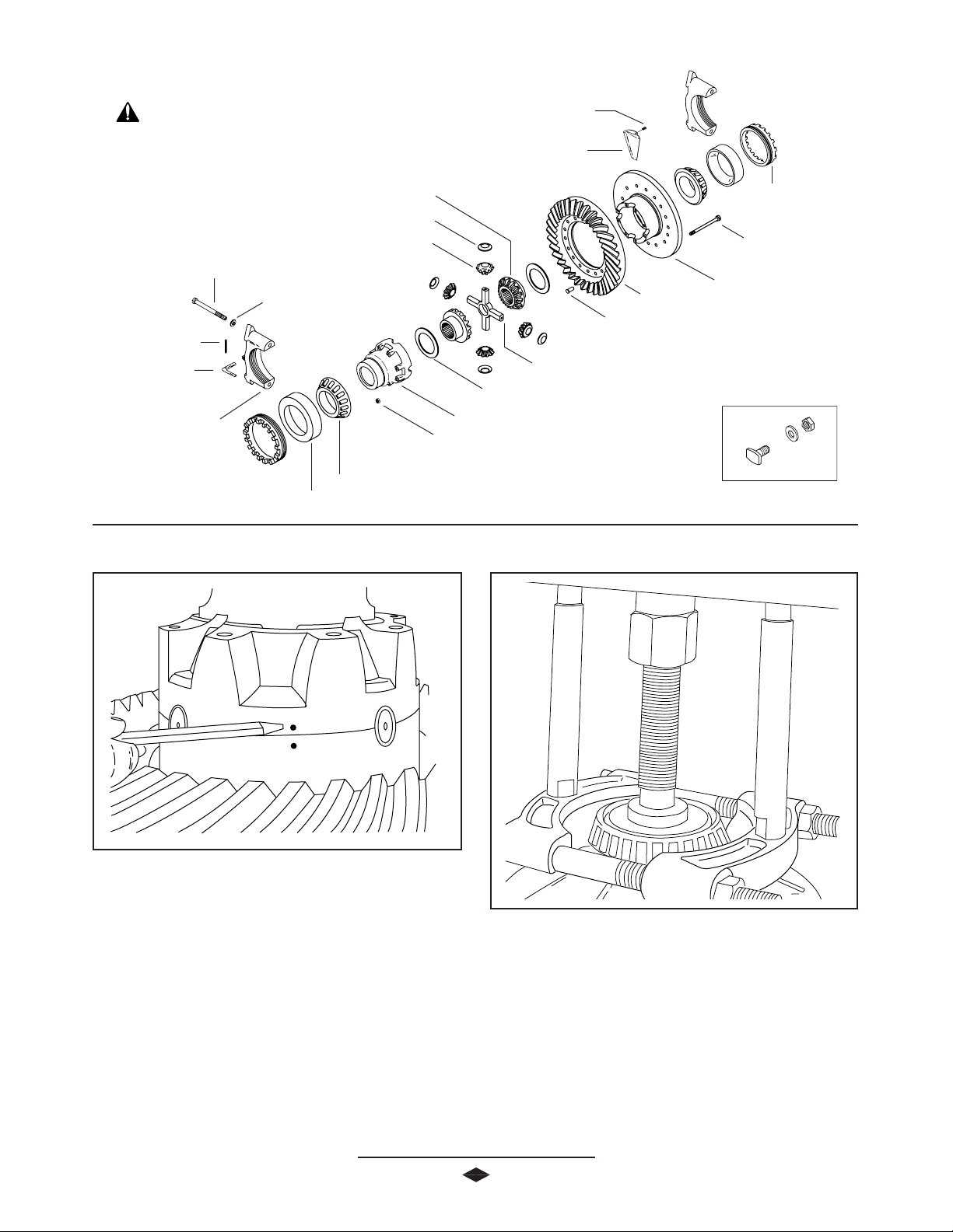
DIFFERENTIAL ASSEMBLY
IMPORTANT: Torque
specifications, shown on illustration,
apply only to J Model. See Page 3334 for W Model torque specifications.
Differential Side Gear
Differential Pinion Mate Thrust Washer
Differential Pinion Mate
Differential Bearing Cap Bolt
(295-340 Lb-Ft)
(370-435 N-m)
Cotter Pin
Adjusting Ring
Lock
Differential Bearing Cap
Differential Bearing
Cap Washer
Differential Bearing Cone
Differential Bearing Cup
Oil Scoop Bolt
(7-9Lb-Ft)
(9-12 N-m)
Oil Scoop
Differential Cross Shaft
Differential Gear Thrust Washer
Differential Case Cap Half
Differential Case Nut
(160-180 Lb-Ft)
(218-245 N-m)
Adjusting Ring
Differential Case Bolt
(160-180 Lb-Ft)
(218-245 N-m)
Differential Case Flange Half
Ring Gear
Ring Gear Rivet
(40-45 tons)
(41-50 metric tonnes)
Ring Gear Bolt Kit
(300-320 Lb-Ft)
(406-434 N-m)
(Optional)
1. If ring gear was removed from differential case, reinstall at
this time. Clean mating surfaces and bolt ring gear to
differential case at 3 locations, 120º apart to help
eliminate ring gear runout. Use hydraulic press and
suitable riveting fixture, as shown. Pressure requirement
per rivet is 45-50 tons (41-45 metric tonnes).
The ring gear is properly installed when a .0015” (.038
mm) feeler guage cannot be inserted between the
differential case flange and the ring gear backface. See
Figure 14.
NOTE: Ring gear and pinion must be replaced as a match set
only.
2. Install bearing cones to differential case halves.
Place bearing cups on cones during remainder of
assembly to prevent damage to bearings.
NOTE: Use of press and proper adapter is required to
eliminate possible damage to bearings.
3. Apply a small amount of lubricant to all mating surfaces.
This will keep thrust washers in place during assembly and
provide initial lubrication.
4. Place thrust washer and side gear in flange half of
differential case. Dimples in thrust washers go against
side gear.
5. Assemble differential pinions and thrust washers on cross
shaft. Place assembly in flange half differential case.
6. Place remaining side gear and thrust washers in position
on differential pinions.
7. Assemble case halves, making sure that both match marks
are lined up.
FF
F
igur
FF
igurigur
igurigur
e 1e 1
e 1
e 1e 1
8. Install differential case bolts. Tighten alternately and
evenly. (See Torque Specifications Chart, Pgs. 33-34)
Differential Assembly Complete
44
4
44
22
Page 25

Oil Pick-Up Plate
1. Three differential cases are used with the W Model
carriers, depending on the ratio. Two of the cases
have two oil pick-up plates attached. Clean and coat
bolts with Loctite #271 or its equivalent. Assemble
and torque bolts to 7-9 Lb-Ft (9-12 N-m)
CAUTION: Differential assembly must be aligned
within bearing bores before preload is applied or damage to
bearings could occur.
2. Install ring gear and differential assembly into carrier
housing.
CAUTION: To avoid damage of the ring gear and pinion, care
should be used when installing the ring gear differential
assembly into the carrier housing.
DIFFERENTIAL INSTALLATION
FF
igurigur
e 1e 1
55
F
igur
e 1
5
FF
igurigur
e 1e 1
55
6. Check ring gear and pinion backlash in four equally
spaced positions around the ring gear with a dial
indicator as shown. Acceptable backlash tolerance
is .006"-.012". See Figure 16.
NOTE: If backlash tolerance varies more than .003" (.080
mm) between the four positions, remove the differential and
determine the cause.
7. Once backlash is set, torque the differential bearing
cap bolts to 295-340 Lb-Ft (397-460 N-m). Check
backlash after torquing cap bolts.
3. Be sure side bearing cups are seated on bearing cones.
Assemble differential bearing caps, with match marks in
proper location. Clean differential bearing cap bolts and
washers and coat threads with Loctite #277 or its
equivalent. Install bearing cap bolts and tighten enough
to eliminate visible space between differential bearing cap
and carrier housing. Do not torque the cap bolts at this
time.
4. Install adjusting rings. Tighten both adjusting rings
until end play is eliminated and there is backlash
between the ring gear and pinion. See Figure 15.
5. Loosen adjusting ring on tooth side of ring gear 1 notch
and tighten adjusting ring on flange side of ring gear 1
notch. Repeat process until backlash is eliminated.
Tighten adjusting ring on tooth side of the ring gear 2 or
3 notches or until proper backlash and side bearing
preload are established.
23
FF
igurigur
e 1e 1
66
F
igur
e 1
6
FF
igurigur
e 1e 1
66
Differential Installation Complete
Page 26

OUTPUT SHAFT ASSEMBL Y
Flanged Hex Nut
(500-600 Lb-Ft)
(678-813 N-m)
Output Shaft Bearing
End Yoke Assembly (Output)
Output Shaft Oil Seal
Output Shaft Bearing Cage
Bolt
(30-40 Lb-Ft)
(41-55 N-m)
Snap Ring
Output Shaft
1. Support output shaft bearing and press output shaft into
bearing.
2. Install bearing cage over bearing and secure with snap
ring.
NOTE: To insure proper end play, both inner and outer
bearings are in matched sets with spacers. Do not mix
separate bearings.
CAUTION: Use only enough pressure to lightly seat
bearings against the thick spacer. Excessive pressure could
damage the assembly.
3. Install new seal using seal installer tool (See Recom-
mended Service Tools, Pgs. 35-36).
4. Install end yoke using yoke installer tool (See Recom-
mended Service Tools, Pgs. 35-36) and place washer
onto shaft. Clean and dry threads, then coat with Loctite
#680 and torque to 500-600 Lb-Ft (678-813 N-m).
5. Clean mating surface on axle housing and output shaft
bearing retainer. Apply a 1/16” bead of Loctite #518
Gasket Eliminator on housing mounting flange and around
bolt holes. Install output shaft, with lube trough to
bottom. See Figure 17. Tighten mounting bolts evenly to
30-40 Lb-Ft (41-55 N-m).
6. Install rear drive shaft.
Loctite #518
Lube Trough
24
FF
igurigur
e 1e 1
77
F
igur
e 1
7
FF
igurigur
e 1e 1
77
Output Shaft Assembly Complete
Page 27

Idler Gear Shaft
Air Shift Cylinder
Retainer Clip
Retainer Spring
Air Shift Cylinder Bolt
(30-40 Lb-Ft)
(41-55 N-m)
Shift Fork Shaft
(30-38 Lb-Ft)
(41-51 N-m)
Idler Gear Front Bearing Cone
Idler Gear Front Bearing Cup
Idler Gear
Idler Gear Bearing Spacer (Selective)
INTERMEDIA TE CASE ASSEMBLY
IMPORTANT: Torque
specifications, shown on illustration,
apply only to J Model. See Page 3334 for W Model torque specifications.
Idler Gear Front Bearing Cup
Idler Gear Front Bearing Cone
Inter-Axle Differential Case
Idler Shaft Nut
(500-600 Lb-Ft)
(678-813 N-m)
Shift Fork
Inter-Axle Differential
Case Bolt
(75 -90 Lb-Ft)
(101-122 N-m)
1. Install bearing cups into the idler gear. Be certain cups
are pressed completely into or improper measurement of
end play will result.
2. Install bearing spacer and bearings into idler gear. The
end play is controlled by the bearing spacer.
3. Install idler gear into intermediate case. Slide gear into
position.
4. Install idler shaft into idler gear and intermediate case.
Drive Gear Bearing Cup
Drive Gear Bearing Cone
Input Drive Gear
Inter-Axle Differential Bearing Cone
Inter-Axle Differential Bearing Cup
Shift Collar
The plate accomplishes two things:
A. It positions the idler shaft properly to facilitate assembly
of the intermediate case to the differential carrier housing.
B. It retains the input gear bearing cup in the
intermediatecase when checking end play of the inter-axle
differential.
8. Turn intermediate case over. Install a new prevailing
torque nut.
5. Install input gear bearing cup into intermediate case. Use
of Loctite to help retain bearing cup in case is recommended.
IMPORTANT: A special plate has been designed to aid in
assembly. A print of the special plate is provided for your
convenience. See Pg. 19.
25
9. Retain intermediate case to eliminate movement.
Use a torque multiplier wrench and torque idler
shaft nut to 500-600 Lb-Ft (675-800 N-m).
10 . The idler gear is designed to run with end play. Using a
dial indicator, check end play. End play should be .001”
to .006”. If it is not to specification, change bearing
Page 28

INTERMEDIA TE CASE ASSEMBLY
spacer. Use a thinner spacer to decrease end play or a
thicker spacer to increase end play. Any preload on the
gear bearing will cause premature bearing failure.
11 . Assemble bearing cones onto front and tear of input gear
and install input gear assembly into intermediate case.
Rotate to make sure it is seated properly.
12 . Assemble shift fork onto shift collar and install into
intermediate case. Be sure the boss on the shift fork is
pointing up or towards the inter-axle differential before
installing. Unit will not shift correctly if installed improperly.
13 . Apply Loctite #290 to threads of shift fork shaft.
FABRICATE SPECIAL PLATE FROM 3/8” STEEL
14 . Install shift fork shaft into intermediate case and thread
into shift fork. Torque shaft to 30 to 38 Lb- Ft (41-52 Nm). Place spring over shaft. Compress spring and install
retainer clip into groove in shaft. Intermediate case is now
ready for assembly of inter-axle differential.
Intermediate Case Assembly Complete
23.292mm
4.625"
117.475mm
54.381mm
1.96"
49.784mm
.917"
2.141"
2.290"
58.166mm
45
5.281"
134.137mm
5.063"
128.600mm
2.593"
65.862mm
3.78 DIA.
96.012mm
9.843"
250.012mm
81.737mm
1.187"
30.149mm
3.218"
48.412mm
3.968"
100.787mm
1.906"
25
3.052"
77.520mm
.323"
8.204mm
101.600mm
4.063"
103.200mm
4.000"
3.468"
88.087mm
7.531"
191.287mm
26
Page 29

Spiral Snap Ring
Inter-Axle Differential Rear Bearing
Input Bearing Cone
Input Bearing Cup
Shim (Selective)
INTER-AXLE DIFFERENTIAL ASSEMBLY
Inter-Axle Differential Case
Assembly
IMPORTANT: Torque
specifications, shown on illustration,
apply only to J Model. See Page 3334 for W Model torque specifications.
Fill Plug
Inter-Axle Differential Cover
Pinion Oil Seal
End Yoke
Assembly
Inter-Axle Differential
Cover Bolt
(75-90 Lb-Ft)
(102-122N-m)
1. Press input bearing cone onto inter-axle differential case
assembly. Install bearing cup into differential cover
without shims.
2. Install inter-axle differential case assembly into
intermediate case. Then place the inter-axle
differential cover on top of the inter-axle differential
assembly. (the inter-axle differential rear bearing should
not be installed at this time)
3. Secure inter-axle differential cover into place with
four bolts. Bolts do not have to be torqued, but
should be enough to prevent movement.
4. Position a dial indicator on input shaft of inter-axle
differential. See Figure 18. Use a lever arm and pry
differential up to measure end play. Record this
dimension. Remove inter-axle cover and inter-axle
differential. Remove bearing cup from cover.
5. End play for the inter-axle differential is .001-.005.
From the dimension recorded in step 4, subtract
.001-.005 for correct shim required.
Flanged Hex Nut
(900-1,200 Lb-Ft)
(1,220-1,627N-m)
FF
igurigur
e 1e 1
88
F
igur
e 1
8
FF
igurigur
e 1e 1
88
EXAMPLE
.080 in. (2.032 mm) Dial indicator measurement
-.003 in. (.076 mm) Preferred end play
.077 in. (1.956 mm) Shims required
Install proper shim and bearing cup into inter-axle cover.
6. Press inter-axle differential rear bearing onto rear case of
inter-axle differential cover.
7. Assemble spiral snap ring onto differential case. Be sure
snap ring is completely seated into groove.
27
Page 30

INTER-AXLE DIFFERENTIAL ASSEMBLY
8. Install input seal into inter-axle cover. Apply a light coat
of lubricant onto seal prior to installation. Assemble end
yoke onto input shaft of inter-axle differential. Mount
end yoke in vise.
9. Clean and dry threads. Coat threads with Loctite
#680 and torque nut to 900-1,200 Lb-Ft
(1,220-1,627 N-m). See Figure 19.
10 . Apply 1/16" bead of Loctite #518 Gasket Eliminator to
mating surface on rear side of input shaft bearing retainer.
See Figure 20. Position retainer onto intermediate case.
Install bolts and tighten to 75-90 Lb-Ft (102-122 N-m).
Again check end play to assure proper setting.
Figure 20Figure 20
Figure 20
Figure 20Figure 20
12 . Torque mounting bolts to 30-40 Lb-Ft (41-55 N-m).
13 . As a check, connect air line to power divider control to be
certain it is operable. There should be a distinct “clunk”
sound when air is applied.
FF
igurigur
e 1e 1
99
F
igur
e 1
9
FF
igurigur
e 1e 1
99
11 . Apply 1/16" bead of Loctite #518 Gasket Eliminator
onto mounting surface next to cylinder and install onto
intermediate case. See Figure 21.
Inter-axle Differential Assembly Complete
FF
F
igur
FF
igurigur
igurigur
e 2e 2
e 2
e 2e 2
11
1
11
28
Page 31

RING GEAR AND PINION TOOTH CONT ACT PA TTERN
The procedures to the right are to be used to establish proper
gear tooth pattern after assembly of the carrier is complete.
NOTE: If matched sets are being reused, measure and record
backlash before disassembly, and reassemble to the same
backlash. This will match ring and pinion gears to the established wear patterns. Hand rolled patterns will cover less area
than the gear pattern established by previous service.
Gleason cut gears and Oerlikon cut gears can be identified by
using the following chart.
Example: Gleason cut Wmodel, 584282C1.
J Model W Model
Gleason 047GX1XX XXXXXXC1
XXXXXXR1
Oerlikon ------ 057GX2XX
STEP 1. Paint 1/4 ring gear with marking compound on
both the drive and coast side.
STEP 2. Rotate ring gear at least one complete revolution in
both directions while load is being applied.
CORRECT GEAR P ATTERNS FOR GLEASON CUT GEARS
LIGHTLY LOADED
HEAVILY LOADED
CORRECT GEAR P ATTERNS FOR ORLIKON CUT GEARS
LIGHTLY LOADED
HEAVILY LOADED
NOTE: Tooth contact pattern, on this axle model, can be moved only by adjusting backlash. The contact pattern can be moved in
the direction of heel-to-toe, and toe-to-heel; Depth of the pattern cannot be adjusted. If an acceptable tooth contact pattern
cannot be established within limits of backlash, contact Spicer Service at 1-800-666-8688.
29
Page 32

INST ALLATION OF INTER-AXLE DIFFERNETIAL TO CARRIER
1. Thoroughly clean mating face of carrier and apply an 1/8
inch bead of Loctite #518 Gasket Eliminator. See Figure
21 for correct bead pattern.
2. Align inter-axle differential case with carrier housing and
insert bolts and torque to 160-180 Lb-Ft (217-244 N-m).
#518 Gasket Eliminator Bead Pattern
FF
igurigur
e 2e 2
11
F
igur
e 2
1
FF
igurigur
e 2e 2
11
YOKE REMOV AL AND SEAL REPLACEMENT
1. Disconnect drive shaft at the rear U-joint.
2. Remove yoke nut.
NOTE: Use of torque multiplier is recommended as torque
specification on input flanged hex nut is 900-1,200 Lb-Ft
(1,220-1,627 N-m).
3. Remove end yoke using the yoke remover tool. See
Figure 22.
4. Remove oil seal.
5. Inspect end yoke seal surface for grooves. If grooves can
be detected with fingernail, it should be repaired with a
®
CR SPEEDI-SLEEVE
6. Clean and dry threads on input/ouput shaft or
pinion. Install oil seal using proper tools.
7. Install end yoke using yoke installer.
NOTE: Spicer recommends that new flanged hex nuts be used.
or replaced.
8. Apply Loctite #680 (green) to threads.
9. Use torque multiplier and torque flanged hex nut to 900-
1,200 Lb-Ft (1,220-1,627 N-m).
Yoke Remover
Figure 22Figure 22
Figure 22
Figure 22Figure 22
Yoke Removal and Seal Replacement Complete
30
Page 33

INST ALLATION OF DIFFERENTIAL CARRIER TO AXLE HOUSING
1. Thoroughly clean the inside of the carrier housing and
inspect the housing mounting surface for nicks and general
cleanliness. Stone the surface if necessary to remove burrs
or nicks. Bolt holes must also be checked to see that they
are free of contaminants.
Loctite #518
Gasket Eliminator
Figure 23Figure 23
Figure 23
Figure 23Figure 23
8. Install the axle shafts to proper location. Torque the axle
flange nuts to vehicle manufacturers specifications.
9. Clean drain plug and install. Torque drain plug to 35-45
Lb-Ft (47-61 N-m). Fill unit to proper level with hypoid
gear lubricant.
10. Install fill plug and torque to 35-45 Lb-Ft (47-61 N-m).
NOTE: Lubricant close enough to bottom of fill hole to be seen or
touched is not sufficient. Lubricant must be level with the fill hole.
2. Apply an 1/8“ (3.175 mm) diameter bead of Loctite
#518 Gasket Eliminator onto the axle housing mounting
flange and around each bolt hole. See Figure 23.
3. Thread two studs into the axle housing 180º
apart. This
will eliminate rotation of the carrier assembly after it
makes contact with the gasket material.
4. Install the carrier assembly into the axle housing. If
reinstalling used bolts, clean the mounting bolts, and coat
with Loctite #277, and install. Tighten bolts evenly in a
crossing pattern. Torque bolts 240-260 Lb-Ft (325-352
N-m).
5. Allow one hour cure time for gasket material before
adding hypoid gear lubricant.
6. Remove the old axle flange gasket and clean mating
surfaces of the hub and axle flange.
7. Install the new axle flange gasket.
CAPACITIES (Approximate*):
J Models Pints Liters
Forward Rear 33.5 16.0
Rear Rear Axle 26.5 12.7
W Models Pints Liters
Forward Rear 35.5 16.9
Rear Rear Axle 28.5 13.6
* Lube capacity will vary depending upon the housing angle in each
vehicle. Capacities given above are for an angle of 4 degrees. Fill to
the lower edge of the fill hole in the axle housing as shown above.
** Pour 1 Pint (0.5 Liter) of gear lube into the filler hole in top of
Inter-axle Differential cover.
31
Page 34

WHEEL BEARING ADJUSTMENT
,,,
,,
,
NOTE: Wheel bearings should be adjusted following vehicle
manufacturers recommended maintenance schedule.
1. Block wheels not being adjusted to insure that vehicle will
not roll. Release emergency brake.
2. Raise wheel to be adjusted off of the ground. Make certain
wheel rotates freely.
3. Remove axle shaft.
4. Remove outer adjusting nut and lock if tabs are broken.
5. Torque inner wheel nut to 50 Lb-Ft (68 N-m) while
rotating wheel one direction, then the other direction.
Back off inner nut 1/4 turn.
NOTE: When replacing wheel bearings, new bearings must be
seated to insure maximum service reliability. After the hub and
bearings are assembled in place on the spindle, install the
inner adjusting nut. Tighten the inner adjusting nut to 120 140 Lb-Ft (163-190 N-m), while rotating the hub to seat the
bearings. Back off the adjusting nut 1/2 turn and follow the
procedure outlined in step #5.
LUBRICANT LEVELLUBRICANT LEVEL
LUBRICANT LEVEL
LUBRICANT LEVELLUBRICANT LEVEL
6. Install lock against inner wheel nut, with locking portion
positioned on either the flat side of inner nut or peak of
inner nut, as shown.
7. Install outer wheel nut and torque to 250-275 Lb-Ft
(340-373 N-m). Rotate wheel in both directions. Wheel
must rotate freely, without binding.
8. Bend one tang of lock over flat portion of outer wheel to
secure.
9. Remove old axle flange gasket and clean mating surfaces
of hub and axle flange.
10 . Install new axle flange gasket.
11 . Install axle shaft. Torque axle nuts to specifications. (See
Axle/Torque Specifications, Pg. 33).
32
Page 35

Axle Specifications
AXLE / TORQUE SPECIFICA TIONS
Description
J Models
U.S. Metric
W Models
U.S. Metric
Pinion
Nominal Dimension 3.976 in. 95.745 mm 4.2845 in. 108.826 mm
Bearing Preload (Torque Wrench) 10-30 Lb-in 1.1-3.4 N-m 10-30 Lb-in 1.1-3.4 N-m
Differential
Ring Gear to Pinion Backlash .010-.013 in. .25-.33 mm .012-.016 in. .30-.40 mm
Ring Gear Rivet Pressure 45-50 tons 41-45 tonnes 50 tons 45 tonnes
Power Divider
Inter-axle Differential End Play .001-.005 in. .03-.12 mm .001-.005 in. .03-.12 mm
Idler Gear Bearing End Play .001-.006 in. .03-.15 mm .001-.006 in. .03-.15 mm
Lubrication (Approx.**)
Forward Rear Axle 33.5 16.0 35.5 16.9
Rear Rear Axle 26.5 12.7 28.5 13.6
* Pinion bearing preload is established prior to installation of pinion seal.
** Capacity will vary depending on the housing angle in each vehicle. Fill to lower edge of fill hole in rear of axle housing as shown on Page 30.
§ Pour 1 Pint (0.5 Liter) of gear lube into filler hole in top of inter-axle differential cover.
Axle Specifications
Position Model
Thread
Grade
Lb-Ft
N-m
Axle Flange to J340-S Only 5/8-18 5 Nylok 125-145 170-195
Wheel Hub Nuts*** J380-S thru W460-S 3/4-16 5 Nylok 217-240 290-325
Axle Flange to J340-S Only 5/8-18 8 Steel 160-185 220-250
Wheel Hub Nuts*** J380-S thru W460-S 3/4-16 8 Steel 275-320 370-435
NOTE: Refer to vehicle manufacturer specifications for axle Flange-Wheel Nut fastener torque.
*** Axle flange mounting nuts are either a grade 5 nylon (Nylok) locking nut, or a grade 8 steel locking nut. Torque to specification shown in
chart above.
33
Page 36

AXLE / TORQUE SPECIFICA TIONS
Power Divider Fasteners
Position Thread
Grade
Lb-Ft N-m
Flanged Hex Nut, Input 1 3/4-12 900-1,200 1,220-1,267
Flanged Hex Nut, Output 1 1/2-18 500-600** 680-816**
Idler Shaft Nut 1 1/4-18 500-600 680-816
Inter-axle Differential Cover Bolt (Hex) 1/2-13 8 75-90 101-122
Intermediate Case Bolts (Flanged) 1/2-13 8 75-90 101-122
Output Shaft Retainer Bolts 3/8-16 8 30-40 41-55
Shift Fork Shaft 1/2-13 30-38 41-52
Air Shift Cylinder Bolts 3/8-16 8 30-40 41-55
** Threads must be cleaned and dried, and coated with Loctite#518 adhesive compound, or its equivalent.
Forward/Rear Axle Common Fasteners
Position Thread
GradeModel
Lb-Ft N-m
Castillated Pinion Nut All Fwd Carriers 1 3/4-12 600 Min.* 815 Min.*
Flanged Hex Nut, Rear All 1 3/4-12 900-1,200** 1,220-1,627**
Pinion Bearing Cage Bolts (Hex) All Fwd Carriers 9/16-12 5 115-135 155-183
Pinion Bearing Cage Bolts (Hex) All 5/8-11 5 160-180 218-245
Pinion Bearing Cage Bolts (Flanged) All 5/8-11 8 240-260 326-352
Differential Bearing Cap Bolts (Hex) All 3/4-10 5 275-320 373-433
Differential Bearing Cap Bolts (Flanged) All 3/4-10 8 295-340 400-460
Differential Case Nuts J 9/16-18 8 115-135 155-183
Differential Case Nuts W 5/8-18 8 160-180 218-245
Carrier Mounting Bolts (Hex) All 5/8-11 5 160-180 218-245
Carrier Mounting Bolts (Flanged) All 5/8-11 8 240-260 326-352
Differential Case Oil Scoop Bolts All 1/4-20 8 7-9 9-12
Oil Pipe Plugs All 3/4-14 8 35-45 47-61
Ring Gear Bolt Kit All M16 x 1.5-6G 300-320 406-434
*
If roll pin cannot be installed after minimum torque is attained, the nut must be advanced until roll pin can be installed.
** Threads must be cleaned and dried, and coated with Loctite#518 adhesive compound, or its equivalent.
34
Page 37

RECOMMENDED SERVICE TOOLS
ILLUSTRA TION ORDER NUMBER
DESCRIPTION
DST1001 CARRIER STAND
DST1002
TORQUE MULTIPLIERS
Maximum 1,000 Lb-Ft
DST1003
Maximum 2,000 Lb-Ft
DST1004
DST1005
Maximum 4,000 Lb-Ft
Maximum 12,000 Lb-Ft
DST1006
DST1009
35
YOKE REMOVER, BAR TYPE
INSTALLER, DIFFERENTIAL YOKE
1/4
"- 12)
(1
Page 38

RECOMMENED SERVICE TOOLS
J340-S,J380-S,J400-S,W440-S,W460-S TANDEM AXLE KIT
DST1010
ILLUSTRA TION ORDER NUMBER
DESCRIPTION
DST1000-1 SEAL INSTALLATION HANDLE
(To be used with seal installers below)
INPUT/OUTPUT SHAFT
DST1000-2
SEAL INSTALLER
DST1000-3
ALL SERVICE TOOLS AVAILABLE FROM OTC DIVISION:
36
LUBE RETAINER &
REAR PINION SEAL INSTALLER
Service TService T
oolsools
Service T
ools
Service TService T
oolsools
66
55
5 Eisenho5 Eisenho
6
5
5 Eisenho
66
55
5 Eisenho5 Eisenho
OwOw
aa
Ow
a
OwOw
aa
TT
elephone: 1-8elephone: 1-8
T
elephone: 1-8
TT
elephone: 1-8elephone: 1-8
FF
ax Number: 1-8ax Number: 1-8
F
ax Number: 1-8
FF
ax Number: 1-8ax Number: 1-8
ww
er Driver Driv
w
er Driv
ww
er Driver Driv
tt
onna, MN 5onna, MN 5
t
onna, MN 5
tt
onna, MN 5onna, MN 5
00-500-5
00-5
00-500-5
55
060060
5
060
55
060060
00-500-5
00-5
00-500-5
77
7
77
ee
e
ee
33
3-043-04
3
3-04
33
3-043-04
8-78-7
8-7
8-78-7
99
22
9
2
99
22
33
77
55
3
7
5
33
77
55
Page 39

NOTES
36
Page 40

Dana Aftermarket Group
For spec‘ing or service assistance, call 1.800.621.8084 or visit our website at www.spicerparts.com
PO Box 321
Toledo, Ohio 43697-0321
Warehouse Distributor: 1.800.621.8084
Dana Commercial Vehicle Products Group
OE Dealers: 1.877.777.5360
3939 Technology Drive
Maumee, Ohio, USA 43537
www.spicerparts.com
www.dana.com
AXSM-8661 Printed in U.S.A.
Copyright Dana Limited, 2012.
All rights reserved. Dana Limited.
 Loading...