

Page 1
Spicer
Reference:
®
Axles & Brakes
P/N: SHAIS133
WORK INSTRUCTIONS – DANA KIT PART NUMBER: 326837
Kenworth Campaign Number: 01KW7
Kenworth Recall Bulletin Number: C-E-101
Below are work instructions for the replacement of specific tie rod end crosslink and brake assemblies from vehicles equipped with Dana E-1000I
or E-1200I steer axles and Dana ES165-5L ES brakes.
Tie Rod Assembly Replacement
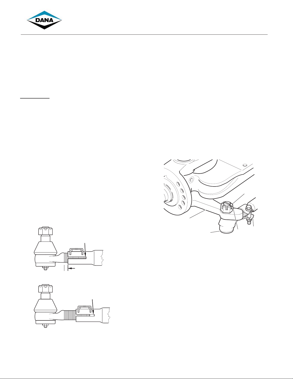
1. Disconnect the tie rod end.
2. If the cross tube is being replaced, count the number of
exposed threads on the tie rod end.
3. Loosen the clamp nut and unscrew the tie rod end.
4. Install new tie rod ends or new cross tube.
NOTE: Cross tube has right-hand and left-hand threads for
corresponding sides of the vehicle.
5. Thread tie rod end into cross tube past the tube split. The
number of threads exposed from the tube should be equal
on both left and right tie rod ends.
CORRECT
The threaded portions of both
tie rod ends must be completely
inserted in cross tube split
Equal threads exposed on
left and right tie rod ends
INCORRECT
Threaded end is not completely
inserted in cross tube split
7. Install tie rod end into knuckle tie rod arm. Secure with
slotted nut and tighten to 120-160 ft. lbs. (163-217 N€m).
3
1
2
1 – Tie rod arm
2 – Tie rod end
3 – Slotted nut
4– Cotter pin
5 – Position clamp fastener away from beam
Figure 2
8. Install the cotter pin in the slotted nut and bend the ends to
secure. If necessary, tighten the nut until the holes align.
9. Adjust toe-in.
NOTE: On tie rods with rotating clamp, position clamp with fastener
away from beam.
4
5
Figure 1
6. Tighten the clamp nut to 45-60 ft. lbs. (61-81N€m). Make
sure the tab on the clamp holds the end of the cross tube.
1
06SE01TBC6298
Page 2
General Information
DANGER: Avoid creating dust possible cancer and lung
!
disease hazard
While Dana does not offer asbestos brake linings, the long-term
effects of some non-asbestos fibers have not been determined.
Current OSHA Regulations cover exposure levels to some
components of non-asbestos linings but not all. The following
precautions must be used when handling these materials.
1. AVOID CREATING DUST. Compressed air or dry brushing
must never be used for cleaning brake assemblies or the
work area.
2. DANA RECOMMENDS THAT WORKERS DOING BRAKE
WORK MUST TAKE STEPS TO MINIMIZE EXPOSURE TO
AIRBORNE BRAKE LINING PARTICLES. Proper procedures
to reduce exposure include working in a well ventilated
area, segregation of areas where brake work is done, use
of local filtered ventilation systems or use of enclosed cells
with filtered vacuums. Respirators approved by the Mine
Safety and Health Administration (MSHA) or National
Institute for Occupational Safety and Health (NIOSH)
should be worn at all times during brake servicing.
3. Workers must wash before eating, drinking or smoking;
shower after working, and should not wear work clothes
home. Work clothes should be vacuumed and laundered
separately without shaking.
4. OSHA Regulations regarding testing, disposal of waste and
methods of reducing exposure for asbestos are set forth in
29 Code of Federal Regulations §1910.001. These
Regulations provide valuable information which can be
utilized to reduce exposure to airborne particles.
5. Material safety data sheets on this product, as required by
OSHA, are available from Dana.
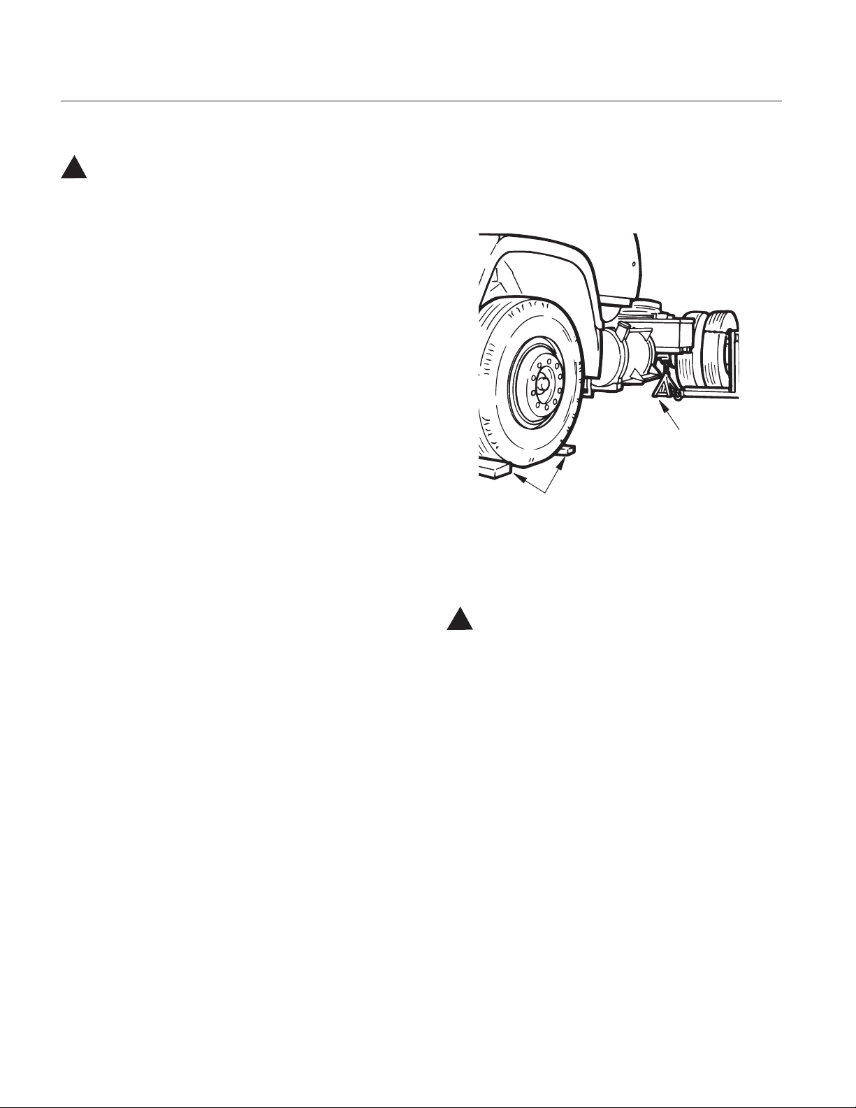
Brake Maintenance Preliminary Steps
Prior to performing any maintenance requiring removal of the tire
and wheel, the following preliminary steps must be taken to ensure
your safety. Refer to Figure 3.
Support On
Jack Stands
of Adequate
Capacity
Block Wheels
Figure 3
1. Set parking brake and block wheels to prevent vehicle
movement.
2. Raise drive axle with a jack and support on suitable stands.
WARNING: Never work under a vehicle supported by a
!
jack.
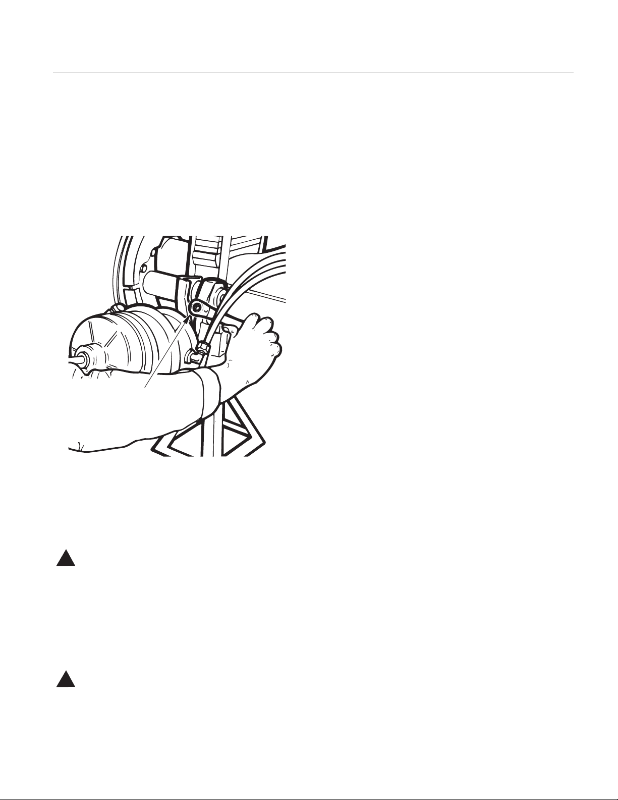
3. Cage spring-type brake chamber following vehicle
manufacturer’s instructions.
2
06SE01TBC6298
Page 3
Removal/Disassembly
Drum Removal
1. Perform “Brake Maintenance Preliminary Steps”.
2. While depressing locking sleeve, back off brake adjuster
adjustment nut on manual brake adjusters. Refer to
Figure 4. Continue turning until shoes are fully returned to
released position and clear of drum. On self adjusting
brake adjusters, follow manufacturer’s instructions.
NOTE: With outboard mounted drums go to step 6.
Turn Adjuster Nut to
Back-Off Adjustment
Figure 4
3. On drive axles, remove stud nuts and axle shafts. If used,
remove Iockwashers and taper dowels. If necessary,
loosen dowels by holding a brass drift in the center of the
shaft head and striking it a sharp blow with a hammer. On
trailer and steer axles, remove hub cap.
WARNING: Do not strike the axle shaft flange with a
!
hammer. Do not use chisels or wedges to loosen shaft or
dowels.
4. Remove axle spindle nut(s) and washer.
5. While rocking drum, pull outboard enough to allow
removal of outer wheel bearing.
6. Remove drum by pulling outboard while rocking from side
to side. If shoes are not clear of drum, return to Step 2
above.
CAUTION: If difficulty is found on removal, do not force
!
drum. Excessive pulling force may damage brake
components.
06SE01TBC6298
3
Page 4

Brake Shoe Removal
EB models (except EB-150-4L)/ ES-165-5D,L / ES-165-6D,L /
ES-165-7D, F, L / ES-150-8D, F / ES-150-4D / ES-150-6D /
ES-165-8D, F, L
1. Perform steps in Removal/Disassembly: Drum Removal.
2. ES-165-5,6,7,8,D,L,F, ES-150-4D, ES-150-8D, F & 6D
ONLY: Pry roller retainer coiled loops out of both shoe web
holes as shown in Figure 5. Pivot roller retainer to swing
loops clear of shoe webs.
NOTE: EB models do not have roller retainers.
3. Using a large screwdriver or lever, lift upper shoe to stretch
return spring as shown in Figure 6.
Lift Upper Shoe
to Stretch Spring
Figure 5
Shoe
Web
Disengage
Retainer Coiled
Loops From
Shoe Webs
Pivot Retainer to
Swing Loops Clear
of Shoe Web
Roller
Retainer
Remove Roller and Pin, Then
Repeat for Lower Shoe.
For ES Brakes, See Note Below
Figure 6
4. Remove upper cam roller and pin.
NOTE: ES-165-5,6,7,8D, L, F, ES-150-4D, ES-150-8D, F & 6D
ONLY: Remove roller and roller retainer as a unit.
5. Repeat Steps 2 through 4 to remove lower shoe roller and
pin.
NOTE: Dana recommends the use of a suitable brake tool when
removing rollers and return springs.
WARNING: The long term effects of non-asbestos fibers
!
have not been determined. Therefore, precautions should
be used when handling these materials.
See General Information / Lining Material Warning
4
06SE01TBC6298
Page 5

6. Push cam end of both shoes toward cam and unhook shoe
return spring. Remove and discard spring.
NOTE: To remove return spring, position a lever or suitable tool
with notch to engage spring rod. Refer to Figure 7. Apply downward
force to stretch spring, allowing removal of upper spring hook.
Remove and discard spring.
Stretch Using Suitable
Tool Positioned
As Shown
Figure 7
7. Rotate both shoes around anchor pin and remove from
vehicle. Refer to Figure 8.
8. Clean and inspect remaining parts as outlined in removal/
disassembly section of this manual.
Rotate Both Shoes
Around Anchor
Pin and Lift Off
Brake Shoes
NOTE: ES-165-5,6,7L,D/ES-150-6D steer axle brakes may use two
return springs with a horse collar or dual spring post. To remove
return springs, position a lever or suitable tool with notch to engage
spring. Return to Figure 7. Apply downward force to stretch upper
spring, allowing removal of upper spring hook. Remove and
discard. Repeat procedure for lower spring.
Figure 8
Figure 9
06SE01TBC6298
5
Page 6

Installation/Assembly
Brake Shoe Installation and Adjustments
All EB (except EB-150-4L) and ES-165 5/6/7/8D, F, L
NOTE: The following procedures are divided into sections,
identified by brake model numbers.
1. See Inspection & Repair / Replacement to verify that
spider camshaft, bracket, and brake adjuster are
serviceable and properly installed.
2. During shoe installation, lubricate:
• Shoe roller recess - one-piece roller.
• Roller I.D. - two-piece roller.
CAUTION: Use only grease conforming to NLGI grade #1,
!
high-temperature, waterproof.
Do Not Lubricate:
• Cam head surface. For efficient operation, this surface
must remain free of oil, grease or other contaminants.
3. Hook ends of new retainer springs into holes in both shoe
tables, hooks pointing out.
4. Position upper and lower shoes around anchor pin. Refer
to Figure 10.
WARNING: The long term effects of non-asbestos fibers,
!
have not been determined. Therefore, precautions should
be used when handling these materials.
See General Information / Lining Material Warning
With Retainer Springs
Installed, Position
Upper and Lower Shoes
Around Anchor Pin
Figure 10
ES-165-D,L,F Only:
Stetch Spring Using Suitable
Tool Positioned as Shown
5. Install a new shoe return spring. Refer to Figure 11.
NOTE: On ES-165-D, 1, F, a lever may be required to assist in
hooking shoe return spring.
Figure 11
6
06SE01TBC6298
Page 7

6. For ES-165 5/6/7/8D, L, F, ES-150-4D, ES-150-8D, F & 6D
only:
Assemble roller retainer on ends of roller as shown in Figure 12.
Install Retainer
on Roller
8. For ES-165 5/6/7/8D, L, F, ES-150-4D, ES-150-8D, F &
6D only:
Position assembly in roller recess as shown. Squeeze loops and
swing retainer into position to snap loops into web holes. Refer to
Figure 14. Verify that both retainer loops are engaged in web holes
before proceeding.
Web
Hole
Figure 12
7. Using a lever or large screwdriver, stretch shoe return
spring to allow insertion of new pin and roller, (or roller
and retainer assembly) on the lower shoe web. Refer to
Figure 13.
NOTE: If drums are oversized, use oversize rollers, see InspectionDrum Inspection.
Stretch
Return Spring,
Install Roller
And Retainer
Figure 13
Install Retainer
Loops in Shoe
Web Holes
Figure 14
9. Repeat process on upper shoe.
NOTE: For all EB Models a roller retainer is not used.
06SE01TBC6298
7
Page 8

Brake Adjustment - Manual Brake Adjuster
NOTE: An assistant is required to make a brake adjustment.
WARNING: Block all wheels before beginning this
!
adjustment procedure
To determine whether Dana Brakes require adjustment, applied
stroke is measured and compared to the maximum value for the air
chamber size in use on the vehicle.
1. Perform “Brake Maintenance Preliminary Steps”
described earlier.
2. With air chamber pushrod fully retracted, measure
distance from face of air chamber to centerline of clevis pin
hole. Refer to Figure 15. If the measurement is not within
ranges shown in Table 1, reposition clevis. Remeasure the
distance and repeat until within range. Record exact
measured distance as dimension “A”.
B
Measure This
Distance
at 80 psi,
Dimension B
Figure 15
Distance: Clevis Pin Hole
Centerline to Air Chamber Face
All brakes (except Mack and
Trailer Axle)
2-5/8” ± 1/16”
(66.7 ± 1.59 mm)
Mack brakes 4-3/8” ± 1/16”
(111.1 ± 1.59 mm)
Trailer Axle brakes 6-1/2” ± 1/8”
(165.1 ± 3.175 mm)
Table 1
A
0HDVXUH7KLV
'LVWDQFHZLWK
&KDPEHUu$W5HVWv
'LPHQVLRQu$v
Figure 14
3. Apply and hold an 80 psi brake application, and again
measure from face of air chamber to clevis pin centerline.
Refer to Figure 16. Record distance as dimension “B”.
4. Subtract dimension “A” from “B”. The difference is applied
stroke. Compare applied stroke to maximum value in
Table 2. If applied stroke equals or exceeds maximum
applied stroke shown, adjust brakes. If less than the
maximum, no adjustment is required and you may perform
Brake Operation Check.
80 - 90 PSI
Air Chamber Size Maximum
Applied
Desired Free
Stroke
Stroke
Type 30” Long Stroke
Type 30”
Type 24”
Type 24” (with 2-1/2”
2.5”
2”
1-3/4”
2”
3/8” to 5/8”
(Without Drag)
extended stroke)
Type 24 (with 3”
2.5”
extended stroke)
Type 20” and 16” 1-3/4” 3/8” to 1/2”
Type 12” 1-3/8” 3/8” to 1/2”
Table 2
NOTE: If adjustment is necessary, Dana Brakes are adjusted to
achieve proper free stroke. The difference between free stroke and
applied stroke is merely the method used to move the brake adjuster
from rest. Applied stroke uses an 80 psi brake application; free
stroke is measured using a lever to move the brake adjuster until the
brake shoes contact the drum. If applied stroke exceeded the
maximum and adjustment is necessary, adjust the brakes as
described in steps 5 through 8 below.
8
06SE01TBC6298
Page 9

5. Take “A” dimension exactly as before. Take “B”
measurement using a lever to move brake adjuster as
shown until the shoes contact drum. Refer to Figure 17.
The result of “B” - “A” is brake free stroke. Adjust free
stroke to within range specified in Table 2.
B
Measure with
Brake Applied
Using Lever,
Lever
Figure 16
6. To adjust free stroke, depress locking sleeve on brake
adjuster adjustment nut and turn in direction required.
Recheck free stroke to verify it is within range. Make sure
sleeve is “locked” when adjustment is completed.
7. Verify that brakes are not dragging by spinning wheels by
hand or tapping drum lightly with a hammer and listening
for a sharp ringing sound.
8. Perform Brake Operation Check, to verify proper
operation of brakes before releasing vehicle for service.
Dimension B
Brake Adjustment - Self Adjusting Brake
Adjuster
1. Brake adjustment for self adjusting brake adjusters is the
same as for manual brake adjusters.
2. Refer to the Self Adjusting Brake Adjuster Manufacturer’s
Instructions for proper installation.
Brake Operation Check
NOTE: An assistant is required to make a thorough brake operation
check.
1. Apply brakes to 80 psi and hold. Check all air line fittings
and air chambers for leakage.
2. Apply and release brakes while observing operation of
brake adjusters on each axle. As brakes are applied and
released, brake adjusters should move in unison visually.
3. Investigate source and make corrections for any
discrepancies found in Steps 1 and 2.
4. Drive vehicle at low speeds in a safe area and make several
brake applications to verify safe operation and absence of
pulling, grabbing, or noise. If any of these are noted,
investigate and repair prior to releasing vehicle for service.
CAUTION: Never release a vehicle for service if any brake
!
discrepancy - no matter how minor - is evident.
06SE01TBC6298
9
Page 10

For spec’ing or service assistance, call 1-800-ÈÓ£nän{ 24 hours a day, 7 days a week, for more time on the road.
Or visit our web site at http://www.ëViÀ«>ÀÌÃ.com.
SHAIS133A September 2001 Copyright Dana Corporation, 2001 Dana Corporation
Printed in U.S.A. All Rights Reserved Commercial Vehicle Axle Division
www.dana.com ККККККККККККККККККP.O. Box ÎÓ£
/i`]Ê"Ê{ÎÈÇäÎÓ£
 Loading...