

EF AutoLite Igniter
Replacement Instruction
Please read this entire instruction before attempting repair.
WARNING - ELECTRIC SHOCK POTENTIAL.
All repairs must be accomplished with the
115VAC and 12 DC power disconnected from
heater.
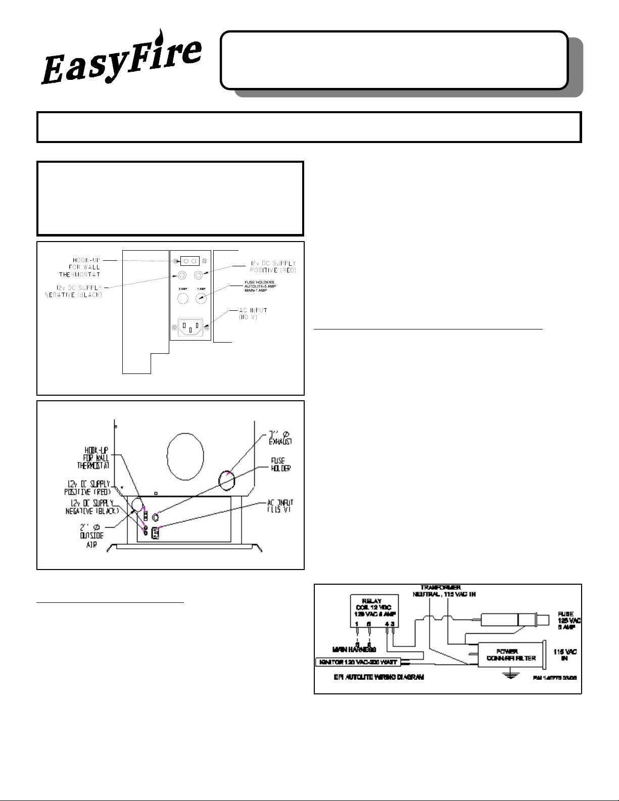
Figure 1 Insert Connection Panel
Basic start up operation is as follows (with thermostat
jumped):
1) From “Off” press operating button (Low). DC controller
energizes the 115VAC relay completing the igniter high
voltage connection. Igniter tem perature im mediately
rises from room temperature.
2) Combustion fan starts at 1 minute along with feed motor
for 1 ½ minutes providing start up fuel.
3) Pellets start to ignite approx. 3 to 4 minutes. Feed motor
starts at 4 m inutes to provide additional start up fuel.
4) At 7 minutes unit should have flame in burn pot. If no
temperature rise is noted by T-1 (sensor) at 20 minutes
heater starts shut down process.
TROUBLESHOOTING IGNITER SYSTEM
The igniter system incorporates a cartridge style high
wattage 115VAC igniter located at the bottom of the pellet
burn pot. This system is continuously cooled by incoming
combustion air and provides years of general service.
However, for the igniter to work properly the burner pot must
be cleaned as required to allow the pellets to fall onto the
igniter. Generally, this is accomplished during normal
cleaning which would include removing the burn pot and
brushing the ash from the pot and igniter. Removing the
screen from below the ignitor and brushing all ash from the
burn pot holder will also aid in the starting process.
Check the igniter rod surface for disintegration or obvious
damage. If any white ceramic material is showing through
the SS protective cover the igniter should be replaced.
Figure 2 Stove Connection Panel
GENERAL INFORMATION
Your EASYFIRE Pellet Heater is equipped with the Autolite
Automatic ignition and operating system.
The AutoLite system is integrated into the heater to allow for
automatic start up using a heating element located in the
burn pot. This element starts the initial fire required to burn
the wood pellets. The system operates on 115VAC power
supplied through a separate fuse for seven minutes during
the initial heater start up. After the seven minute period the
AutoLite system is deactivated and the heater operates
based on the EasyFire digital control system requirements.
If the house AC power should quit, the AutoLite system will
not be available. however, with the optional battery attached
the heater can be manually lit.
Once the burn pot is cleaned and the igniter inspected the
remaining system checks are electrical. A simple check of
the system may be accomplished on a cold heater by
placing a gloved hand on the igniter rod and pressing one of
the operating button (Low). The igniter will start to get hot
immediately (2 minute temperature 500°F). If not
temperature rise is noted then continue with electrical
trouble shooting.
Autolite Wiring Diagram

ELECTRICAL TROUBLE SHOOTING
WARNING: Only a trained technician should attempt to
repair a pellet heater electrical system.
Note: All tests should be accomplished with the unit
thermostat by-passed.
Remove both AC and DC power from unit. The igniter
system is protected with a 5 amp fuse located on the back
or side of the heater (Figure 1). The igniter is switched “Off”
and “On” by the control system via a relay located in the
lower right pedestal in front of the control board
(EF3801/5001) or in lower left rear of the unit accessed
from the back (EF4001). W iring on all igniter systems are
the same. The following test steps will require a multi-meter
with AC/DC volt and ohm functions:
a. Unplug heater from wall outlet and 12VDC power!
b. Remove 5 amp fuse holder cap and fuse by pressing
in and turning counter clockwise. Test fuse with ohm
meter to confirm is not “open”. If fuse is open go to
Testing Igniter “d”. If fuse is good continue.
c. Check 115VAC power wire connection to relay and
neutral wire connection to igniter terminal. This can
be accom plished with the ohm m eter. If wire is
disconnected or open replace.
d. Disconnect igniter leads from relay and neutral. Test
continuity with ohm meter between leads. If open
igniter is defective. If continuity exists then check for
internal grounding by checking each lead to the
shielded conduit of the igniter leads. If continuity
exists to ground then igniter is defective. If meter
reads open on both leads to ground then igniter
should produce heat when properly connected to
115VAC.
e. W ith igniter disconnected from relay, attach volt
meter (set meter to 200VAC) leads to relay 115VAC
out terminal and igniter neutral. Reapply 115VAC
power. Press operating button low. R elay should
imm ediately engage applying 115VAC to m eter. If
meter has 115VAC then replace igniter as it should
be activated. If no AC power outputted from relay.
Continue to next test.
f. Disconnect DC control wires from harness to relay.
Attach volt meter (set m eter to 20VDC) leads to
harness terminals. Reapply 115VAC power. Press
operating button low. Control system should
imm ediately engage applying 12VDC to meter. If
meter has 12VDC then replace relay as it should be
activated. If relay does not engage, exchange control
board and/or main switch board.
REPLACEMENT PARTS:
ITEM
NO.
1 120120 12VDC RELAY
2 120117 CARTRIDGE HEATER
3 120118 AUTOLITE CONTROL SWITCH
4a 202163 BURN POT SCREEN 5001
4b 202164 BURN POT SCREEN 3801/4001
5a 300501 BURN POT 5001-AUTOLITE
5b 300500 BURN POT 3801/4001-AUTOLITE
6 110510 5 AMP FUSE MDL5 (NOT SHOWN)
Customer Service & Replacement Parts
Replacement parts are available from your local dealer or
on-line @ www.sierraproductsinc.net . or call or write:
Customer Service
Sierra Products, Inc.
5061 Brooks St. Ste. B,
Montclair, CA 91763
Phone 1-909-399-3355
Fax 1-909-399-3357
www.sierraproductsinc.net
PART
NO.
DESC RIP TION
Sierra Products, Inc. 5061 Brooks St. Ste. B, Montclair, CA 91763
P/N 140804 10/07
 Loading...