

Page 1

SPHINX Project Eight Service Manual
1
A
SERVICE MANUAL
PROJECT EIGHT
REFERENCE
PRE-AMP
A
Page 2

SPHINX Project Eight Service Manual
2
1. UNPACKING.......................................................................................................................................3
2. SPHINX WARRANTY CARD ..............................................................................................................3
3. CONTACTING THE MANUFACTURER.............................................................................................3
4. TECHNICAL SPECIFICATIONS.........................................................................................................4
5. GENERAL CHECKLIST......................................................................................................................5
Serial number and software version ............................................................................................................5
Input functions .............................................................................................................................................5
Channel imbalance......................................................................................................................................5
Remote Control............................................................................................................................................5
6. SPHINX REMOTE CONTROL............................................................................................................6
Buttons and LED indication .........................................................................................................................6
Operation..................................................................................................................................................... 7
Selecting without switching..........................................................................................................................7
'Learning' the commands.............................................................................................................................7
Changing a command..................................................................................................................................7
Erasing all commands of one component....................................................................................................7
The LED during Normal mode.....................................................................................................................8
The LED during 'Learn' mode......................................................................................................................8
Batteries.......................................................................................................................................................8
Other things worth knowing... ......................................................................................................................8
Encountering problems................................................................................................................................8
7. MEASUREMENTS ..............................................................................................................................9
General set-up............................................................................................................................................. 9
Necessary Equipment..................................................................................................................................9
Audio signal distortion measurement...........................................................................................................9
Set-up ..........................................................................................................................................................9
8. OUTPUT DC-OFFSET ADJUSTMENT.............................................................................................10
Set-up ........................................................................................................................................................10
Adjustment.................................................................................................................................................10
9. PROBLEMS AND SOLUTIONS........................................................................................................11
10. DIAGRAMS AND PARTS LISTS ....................................................................................................12
Figure 1: Front panel .................................................................................................................................12
Figure 2: Rear panel.................................................................................................................................. 12
Index of diagrams and drawings................................................................................................................13
Figure 3: Connection Diagram for testing the Project Eight.......................................................................14
Figure 4: Display Board Schematic Layout................................................................................................ 15
Figure 5: Construction Drawing for top cover plate....................................................................................16
Figure 6: Schematic Operational Diagram Project Eight ...........................................................................17
Figure 7: Schematic Overview of all relevant potentiometers....................................................................18
Figure 8: Disamp-96 ..................................................................................................................................19
Figure 9: Functional Schematic.................................................................................................................20
Figure 10: Left Power Supply.....................................................................................................................21
Figure 11: Right Power Supply..................................................................................................................22
Figure 12: Input/Output..............................................................................................................................23
Figure 13: Left Volume Control..................................................................................................................24
Figure 14: Right Volume Control................................................................................................................25
Figure 15: Left Output Amp........................................................................................................................26
Figure 16: Right Output Amp.....................................................................................................................27
Figure 17: Left Input Amp ..........................................................................................................................28
Figure 18: Right Input Amp........................................................................................................................29
Figure 19: Power Supply Unit....................................................................................................................30
Figure 20: PCB drawings...........................................................................................................................31
Parts List....................................................................................................................................................32
Page 3

SPHINX Project Eight Service Manual
3
The Sphinx Project Eight design
The Sphinx Project Eight was designed for the
ever-increasing group of quality-conscious
audiophiles.
We are very proud of the tradition connected with
the SPHINX name, especially concerning audio
quality perfection.
This service manual will help you to optimally
service and repair the Sphinx Project Eight
Reference Pre-Amp.
This Reference pre-amp uses the newest
technologies and refined designs and is extremely
simple to operate.
Features include ultra-linear extremely low-noise
Class A audio circuits, built from the finest handselected parts.
The signal path is completely balanced from input
to output, and left and right are totally separated.
Volume and balance controls are achieved by
means of precision relays, as is the input selection.
All settings and controls can also be accessed from
the supplied Sphinx Remote Control.
To obtain the maximum quality from this pre amp it
is necessary for it to be properly aligned and to be
used with top quality audio components, preferably
other Sphinx components.
1. UNPACKING
Before leaving the factory every Project Eight is
subjected to stringent and extensive technical and
exterior quality inspection. This ensures the user
many years of high quality audio from a perfectlooking product.
We recommend owners to ship the Project Eight in
its original carton.
After unpacking the Project Eight we therefore
recommend you carefully check it for any transport
damage.
If you find any damage and the product has not
been shipped in the original carton the ensuring
repair costs will not be covered by the warranty.
2. SPHINX WARRANTY CARD
To be entitled to any warranty repairs the owner
must have send the filled out warranty card to
Sphinx or a distributor where it has been registered.
Other regulations may apply in your specific
country: when in doubt, please consult the proper
authorities.
3. CONTACTING THE MANUFACTURER
In case of any problem not covered in this manual
or if you have other questions you may contact the
Sphinx International Service Department in The
Netherlands (local time: GMT +1h) during office
hours at the following numbers:
Telephone (+31) 35 602 0302
Fax (+31) 35 602 2806
E-mail audionl@euronet.nl
It is always very helpful and efficient if you have all
relevant information about the specific product and
the problem ready.
Please also refer to the User Manual of the
Project Eight for information about functions
not described in this manual.
It is important to familiarise yourself with the
special functions, operation and possibilities
of the Sphinx Project Eight.
Page 4

SPHINX Project Eight Service Manual
4
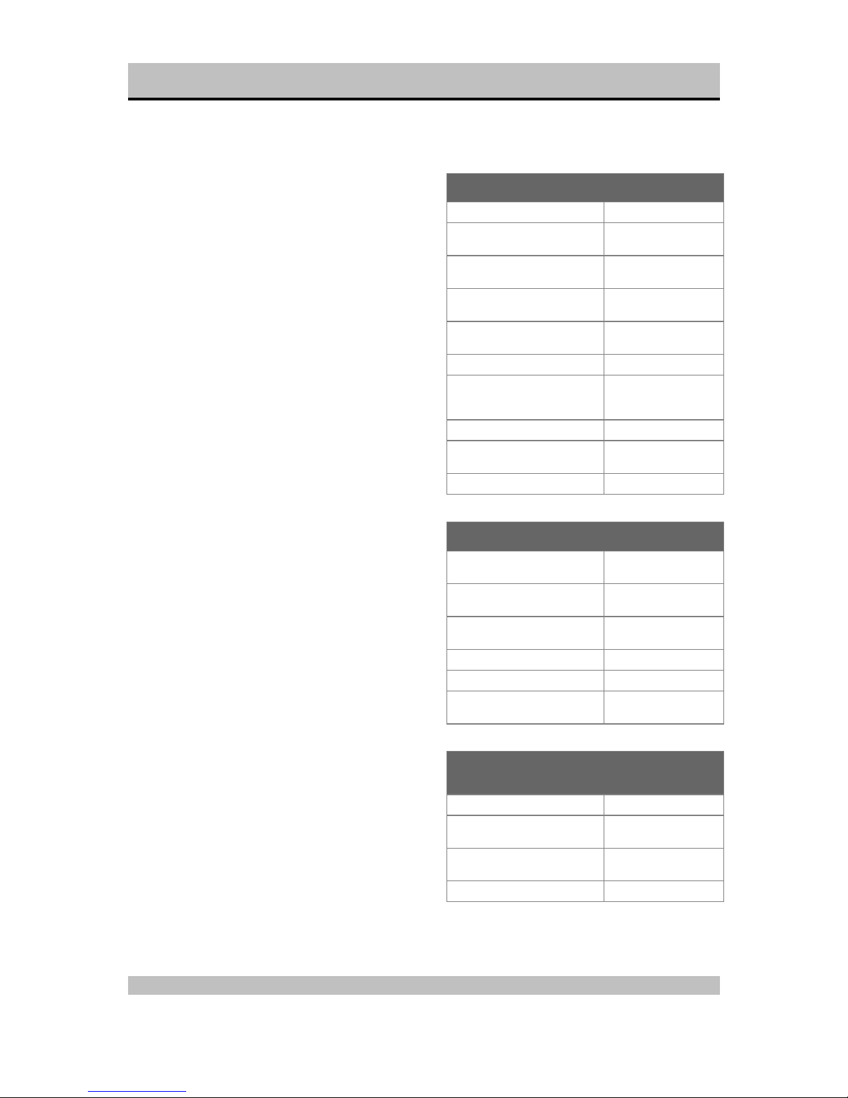
4. TECHNICAL SPECIFICATIONS
Bandwidth 0 - 500,000 Hz (+0/-3 dB)
Phase response error <1°
Gain 20 dB max.
THD+N (IHF-A) <0.008% (2nd harm., < 100 kHz and 6 V into 600 ohm)
<0.0015% (2nd harm., 10 – 20,000 Hz and 6 V into 600
ohm)
IMD <0.0015%
S/N ratio (IHF-A) >110 dB
Channel separation >110 dB
Inputs 2x XLR balanced
6x WBT cinch unbalanced
Level, nominal (for 1 V output) 0.16 V (-18 dBV)
Impedance XLR: 10 kohm / cinch: 50 kohm
Sensitivity (programmable for each input) adjustable between –9 dB and +9 dB
Outputs 2x XLR balanced
1x WBT cinch unbalanced
1x cinch Tape
level 10 V max. (20 dBV) (1 - 100,000 Hz, THD <0.001%)
impedance <10 ohm
Volume control Relay-controlled in steps of 0.2 dB
Range 100 dB
channel imbalance less than 0.2 dB
Sphinx Control 3x optical
OUT-1: 1 second delayed
OUT-2: normal
OUT-3: programmable via Auto On
Remote control full function
Mechanical decoupling of housings Transrotor absorbing 'pucks'
Power supply External, in completely separate housing
Supply capacitance 148,000 µF total
Power consumption 50 W
Dimensions (h x w x d) 68 x 482 x 328 mm (one housing only)
Weight 14 kg
This unit conforms to the EMC interference regulations issued by the EU and to the CE standards.
This unit complies with safety regulation VDE 0860 and therefore with international safety regulation IEC 65.
Technical specifications may be changed by SPHINX without prior notice if technical developments make this
necessary.
Page 5

SPHINX Project Eight Service Manual
5
5. GENERAL CHECKLIST
This checklist should be used for every pre-amp
received.
To correctly perform the following procedures you
may have to refer to the User Manual for more
detailed information on specific functions.
Note: The pre-amp should be switched on at least
1 hour before performing the checklist procedures!
Serial number and software version
The serial number and software version should
match those mentioned in the documentation as
supplied with every Project Eight.
q Switch off the mains power.
q Press the Standby button.
q Switch the mains on again while holding the
Standby button depressed.
q The display will now show the serial number or
software version.
Input functions
All inputs should be checked for the correct:
q Name
q Boost/Attenuation setting
q Polarity
Channel imbalance
For every position (‘step’) of the volume control the
imbalance between Left and Right should never
exceed +/- 0.1 dB.
Remote Control
Each Remote Control is manually programmed
during manufacturing.
Therefore it is important to check whether all
functions work correctly as mentioned in the User
Manual.
See also Chapter 6.
Page 6

SPHINX Project Eight Service Manual
6
6. SPHINX REMOTE CONTROL
This single Sphinx Remote Control lets you control
all functions: not only of the Project Eight, but of all
other Sphinx equipment.
Moreover: you may also use it to control other types
of equipment (e.g. TV and VCR) thanks to the
'learn' mode!
Only the following buttons and indications on the
Remote apply to the Project Eight:
Buttons and LED indication
1. LED: As soon as you press a button this LED
will blink green: the Remote is functioning.
When blinking green/red: batteries running low.
When blinking red: change batteries (see
Batteries).
2. STANDBY: Use this button to switch the Project
Eight to stand-by.
3. PRE-AMP: To select the pre-amp. All buttons
pressed hereafter will control only the pre-amp
functions.
4. 1 - 8: To select inputs input 1 to 8 (Note: 9 and 0
have no function).
5. POLARITY: To change the polarity of the
selected input from + to – (as indicated in the
display).
6. SET-UP: To activate the SET-UP mode,
pressing this button has the same effect as
pressing the PRESETS button on the front
panel.
7. PROGRAM - / +: After activating the SET-UP
mode you can change the parameters with
these two buttons: they have the same effect as
the INPUT control on the front panel.
8. : Pressing this button mutes the outputs
(temporarily) and you will not hear any sound.
The display shows "MUTE". Another press on
this button unmutes the outputs.
9. + button: Pressing this big triangular button has
the same effect as rotating the VOLUME control
on the front panel clockwise. You increase the
volume. The VOL value in the display increases
(to max. 99).
10. — button: Pressing this big triangular button
has the same effect as rotating the VOLUME
control on the front panel anti-clockwise. You
decrease the volume. The VOL value in the
display decreases (to min. OFF).
Page 7

SPHINX Project Eight Service Manual
7
Operation
The Sphinx Remote is used with several different
models and can therefore transmit different control
codes, depending on which model has been
selected with the select buttons (3.).
Important: Always press the PRE-AMP button
before you send a command (even if you only have
one Sphinx component).
Otherwise it is possible that, although the Remote
will send a signal (LED blinks), nothing happens
because the transmitted signal is not 'recognised'
by the component.
Indoors the Remote may be used up to a distance
of 7 meter, provided there is no strong sunlight in
the room and if you aim the Remote at the
component.
Always aim the Remote straight at the front panel of
the component, the maximum offset angle is 30°.
Selecting without switching
Suppose, for instance, that you would like to select
the Tuner to Radio 4 without interrupting CD
playback.
In that case you momentarily depress (not longer
than 0.5 sec) the 'TUNER' button and the '4' button.
The same procedure is used for the other system
components (TV, VCR).
If you depress the select button for longer than 0.5
sec, the system will select a different signal source
(in our example you will then hear the Tuner
playback).
'Learning' the commands
This Sphinx Remote Control is not only preprogrammed for all Sphinx components, but you
can also remotely control your TV and VCR.
The Remote Control is able to 'learn' the
commands from each of the specific remote
controls This will simplify the daily use of your
audio/video system enormously.
The following paragraphs explain how you can
'teach' the Remote Control all those TV- and VCRspecific commands.
1. Place both the Sphinx Remote Control and the
other remote (TV or VCR) flat on a table, facing
each other with a spacing of no more than 2 cm.
Note: Please do not attempt this in direct
sunlight or under strong lighting conditions.
2. Simultaneously press the and TV buttons on
the Sphinx Remote.
The orange LED at the top right-hand of the
Remote will light.
3. Momentarily press the first button on the Sphinx
Remote to be programmed.
The orange LED blinks.
4. Then keep the appropriate button on the other
remote depressed until the LED becomes
green. After releasing the button the LED will
blink orange and you may program the next
button.
5. If the LED is red, repeat steps 3 and 4. If it still
remains red please refer to "Remote does not
'learn".
6. Repeat steps 3 and 4 until all necessary buttons
are programmed.
Note: Do not forget to program the STANDBY
button!
Note: Do not forget to program the TV button
with the "TV-ON"-command!
7. When you are finished press any two buttons on
the Remote to return to Normal mode.
The LED will now be turned off.
Repeat steps 1 to 7 to program the remote for the
VCR (in step 2. you should press the and VCR
buttons). When this is finished your Sphinx Remote
Control is ready for use.
How to operate the Remote Control with the
different Sphinx components is explained in the
corresponding User Manual for each component.
Changing a command
This is done in exactly the same way as described
in the preceding paragraph ‘LEARNING’ THE
COMMANDS, but you now only carry out the
procedure for a certain command and a certain
system component.
Erasing all commands of one component
You may want to erase the commands of one
system component (for instance because you have
bought a new TV).
Simultaneously depress the , Stand-by and
component select button (in our example 'TV'). This
enables the Remote Control to re-'learn' the
commands of the new unit (see also
‘LEARNING’ the commands...).
WARNING!:
If you depress one of the other component
select buttons (than TV or VCR) you will erase
the commands for a Sphinx audio component!
You should only do this if you do not have that
specific Sphinx model, but one of another brand
and want to program the commands of its
remote control.
Page 8
SPHINX Project Eight Service Manual
8
The LED during Normal mode
• Blinks green: Remote sends a command.
• Blinks green/red: batteries are low, you should
change them within a few days.
• Blinks red: replace batteries immediately.
Replace them within 30 minutes or else all
information in memory will be erased!
The LED during 'Learn' mode
• Indicates orange: Remote is in 'Learn' mode.
• Blinks orange: Remote awaits the command to
be 'learned' from the other remote control.
• Indicates green: the new command has been
'learned'.
• Indicates red: the new command has NOT been
'learned'.
• Blinks for 10 seconds red, yellow and green:
memory full, you cannot program new
commands.
Note: You can still change any commands
already programmed.
Batteries
The two batteries have a life span of approximately
one year during normal use, but shorter when used
more intensely.
Replacement batteries: 1.5 V, model penlite or AAA
(one of these codes is indicated on the packaging
and the batteries). You may also use rechargeable
1.5 V batteries.
Do not leave the battery compartment empty for
more than 30 minutes or else all information in
memory will be erased!
Note: Position the new batteries exactly as shown
in the illustration at the bottom of the battery
compartment, otherwise the memory might be
erased completely!
Other things worth knowing...
The 'advanced user' will understand that you can
program any function for any button! You are
therefore able to custom configure the Remote
Control and use it for several pieces of equipment.
The memory holds a maximum of 120 commands.
Warning: If you don't know exactly what you are
doing, please consult your Sphinx dealer!
Encountering problems...
Remote Control does not work
Wrong component selected Select the correct one
Wrong Remote mode ('Learn'
instead of Normal)
Select correct mode
Wrong command programmed Re-program with Learn
mode
Distance to component
exceeds 7 m
Use Remote at closer
range
Angle between Remote and
component exceeds ±30°
Decrease angle
Sensor window on front dirty Clean window
Batteries empty or incorrectly
placed
Use new batteries or
replace the old ones
correctly
Strong (sun)light in room Shade off light source
Component is not switched on
(!)
Switch it on
Memory erased Re-program completely
Remote Control does not 'learn'
Wrong Remote mode (Normal
instead of 'Learn')
Select correct mode
Distance between two remotes
exceeds 2 cm
Place them closer
together
Signal to be learned is not
infrared
'Learning' only possible
with infrared systems
Sensor window on front dirty Clean window
Batteries in remote(s) empty Use new batteries
Strong (sun)light hits sensor
window
Shade off light source
Component reacts differently than expected or
not at all
Wrong component selected Select the correct one
Wrong command programmed Re-program with Learn
mode
Component or Remote does
not function
Check component with
its original remote
Batteries in remote empty Use new batteries
Page 9

SPHINX Project Eight Service Manual
9
7. MEASUREMENTS
To properly service the Project Eight you need
some specific measurement equipment and use a
specific set-up.
General set-up
For the correct measurement set-up and hook-up
please refer to the drawing titled “Figure 3:
Connection Diagram for testing the Project Eight” at
page 14.
Necessary Equipment
q 2x millivolt-meter (Ri >1 MΩ)
q 2x non-inductive load resistor 8 Ω / 250 W
q 1x harmonic distortion analyser
(internal distortion <0.0005%, measured
without filters)
q 1x 2-channel oscilloscope
(minimum bandwidth >60 MHz)
q 1x connection unit / switch box
(to connect resistors and amp outputs to
distortion meter)
Note: See drawing 4. for construction details.
q 2x shorting connector
(for balanced pre-amp inputs)
q 2x balanced cable set
(to connect distortion meter, pre-amp and
power amp)
q 1x special top cover plate (preferably
transparent) with holes for adjustment tools
Note: See drawing 5. for construction details.
q A two channel DC-coupled power amplifier
(e.g. Project Eighteen)
Audio signal distortion measurement
Before adjusting the Project Eight please first
measure the total harmonic distortion at the audio
output. The measured value is an indication of the
current state of the Project Eight.
Set-up
For the correct measurement set-up please refer to
figure 3 at page 14.
q Set the oscillator output level to 0.775 V
(0 dBu).
q Adjust the pre-amp volume control so that
output level equals input level (0 dBu).
q THD should now be 0.1% unweighted (or
0.013% IHF-A).
q Now set volume control to maximum (fully
clockwise).
q Increase the oscillator output of the distortion
analyser to set the pre-amp output just before
clipping.
q THD should now be 0.12% unweighted (or
0.005% IHF-A).
Page 10

SPHINX Project Eight Service Manual
10
8. OUTPUT DC-OFFSET ADJUSTMENT
Proper DC-offset adjustment is very important.
A simple trick will greatly increase the accuracy of
this critical adjustment (see also the drawing titled
“Connection Diagram for testing the Project Eight”
at page 14 ).
By connecting a DC-coupled power amp to the
Project Eight outputs and measuring the offset at
the speaker outputs, the offset is boosted to around
30 times the original value!
Note: We strongly recommend that you use a
power amp with a very low DC-offset, such as the
Project Eighteen.
Note: The pre-amp and the power amp should be
switched on at least 1 hour before performing this
adjustment so they can reach optimum working
temperatures.
Set-up
q Connect a distortion analyser input and a DC
mV-meter to a pre-amp output (or to the power
ampifier). The correct pre-amp output will be
mentioned later.
q Connect the distortion analyser output to a pre-
amp input, the correct input will be mentioned
later.
q Switch off the oscillator of the analyser, this will
short-circuit the pre-amp input.
q Remove the top cover of the Project Eight and
replace it with the special cover plate (with
adjustment holes, see figure 5 at page 16).
Adjustment
For the actual adjustment you may refer to Figure
20 (Main PCB drawing) at page 29 and Figure 7
(Schematic overview of all relevant potentiometers)
at page 17.
In Figure 6 (Schematic operational diagram of
project Eight) at page 16 you will find the placement
of all amps:
Connect the (muted)distortion analyser output to an
unbalanced input of the project eight and select the
correct input at the front panel.
Connect the power amplifier (or, if no power
amplifier is used, the distortion analyser and mVmeter) to the unbalanced output of the project
eight.
The unbalanced signal will only be processed by
disamp A1 & A3 (left channel) and disamp B1 & B3
(right channel). The remaining disamps have no
effect on an unbalanced signal.
q Turn the volume of the project eight to ‘off’. The
offset currently visible on the mV-meter is the
offset of disamp A3(left channel) and/or disamp
B3(right channel).
q This offset can be adjusted by potentiometer
P1 & P2 of disamp A3 for the left channel, and
by potmeter P1 & P2 of disamp B3 for the right
channel.
q Turn the volume of the project eight fully open.
The offset currently visible on the mV-meter is
the offset of disamp A1(left channel) and/or
disamp B1(right channel)
q This offset can be adjusted by potentiometer
P1 & P2 of disamp A1 for the left channel, and
by potmeter P1 & P2 of disamp B1 for the right
channel.
The distortion analyser output must now be
connected to a balanced input of the project eight.
The correct input must also be selected at the front
panel.
The power amplifier (or, if no power amplifier is
used, the distortion analyser and mV-meter ) must
now be connected to a balanced output of the
project eight.
The total offset of all disamps is now visible on the
mV-meter, but since the offset of disamp A1 &
A3(left channel) and disamp B1 & B3(right channel)
has already been adjusted, the offset visible is the
offset of the remaining disamps(A2&A4 and
B2&B4).
Notice: do not commence with the following
procedures before the procedures mentioned
above have been completed.
q Turn the volume of the project eight to ‘off’. The
offset currently visible on the mV-meter is the
offset of disamp A4(left channel) and/or disamp
B4(right channel).
q This offset can be adjusted by potentiometer
P1 & P2 of disamp A4 for the left channel, and
by potmeter P1 & P2 of disamp B4 for the right
channel.
q Turn the volume of the project eight fully open.
The offset currently visible on the mV-meter is
the offset of disamp A2(left channel) and/or
disamp B2(right channel)
q This offset can be adjusted by potentiometer
P1 & P2 of disamp A2 for the left channel, and
by potmeter P1 & P2 of disamp B2 for the right
channel.
Repeat the offset adjustment proceduces a few
times for a perfect adjustment. When this is done,
the offset adjustments are completed
Page 11

SPHINX Project Eight Service Manual
11
9. PROBLEMS AND SOLUTIONS
At the moment of writing the Project Eight has one
known specific problem.
If in the future you encounter any problem(s) you
may enter the info in this table. This table can then
be used for future reference.
Please also send (by fax or e-mail) the specific
information to the Sphinx International Service
Department (see page 3): this info can then be
added to the general database to aid others.
.
Problem Cause Solution Refer to
page…
Volume control doesn’t work
properly
IC U15, U16, U17 or U18 may
be defective.
Replace the defective one. Page 24
Page 25
Page 12
SPHINX Project Eight Service Manual
12
10. DIAGRAMS AND PARTS LISTS
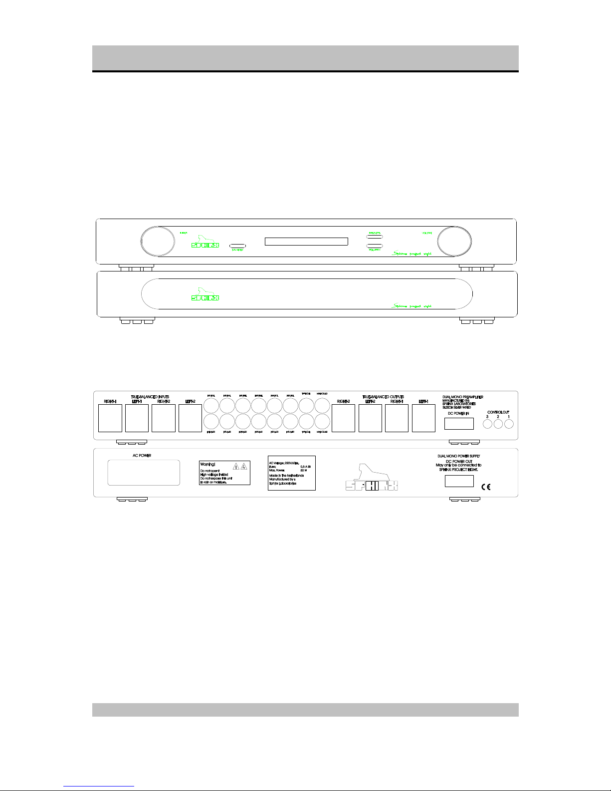
The next pages contain the front and rear panel layout and a complete set of schematic drawings
including the associated parts lists (if applicable).
Figure 1: Front panel
Figure 2: Rear panel
Page 13

SPHINX Project Eight Service Manual
13
Index of diagrams and drawings
Page Description
14 Connection Diagram for testing the Project Eight
15 Display Board Schematic Layout
16 Construction Drawing for top cover plate
17 Schematic Operational Diagram Project Eight
18 Schematic Overview of all relevant potentiometers
19 Disamp-96
20 Functional Schematic
21 Left Power Supply
22 Right Power Supply
23 Input/Output
24 Left Volume Control
25 Right Volume Control
26 Left Output Amp
27 Right Output Amp
28 Left Input Amp
29 Right Input Amp
30 Power Supply Unit
31 PCB drawings
Page 14

SPHINX Project Eight Service Manual
14
Figure 3: Connection Diagram for testing the Project Eight
Right
Left
(+)
(+)
(-)
(-)
Amplfier (30x)
A
B
AMPLIFIER
out1 out2
inp2
inp1
gnd
THD
Amplitude
Frequency
Oscillator
THD out
(+) (-) (+) (-)
Right
Left
(+)
(+)
(-)
(-)
Pre-amplfier (3x)
A
B
(+)
(+)
(-)
(-)
PRE-AMPLIFIER
out1 out2
inp2inp1
Scoop
SWITCH-BOX
x
y
inp2
time/div
inp1
gnd
Page 15

SPHINX Project Eight Service Manual
15
Figure 4: Display Board Schematic Layout
Xtal10EXtal11MD112MD013NMI14VCC15STBY16GND17P4019P4120P4221P4322P4423P4524P4625P47
26
nc
18
P50
27
P51
28
P52
29
P53
30
P54
31
P55
32
P70
33
P71
34
nc
35
P72
36
P73
37
P74
38
P75/WR
39
P76/RD
40
P77
41
VCC
42
P27
43
RES
9
P66
8
P65
7
P64
6
P63
5
P62
4
P61
3
P60
2
nc
1
P30
61
P31
62
P32
63
P33
64
P34
65
P35
66
P36
67
P37
68
P2644P2545P2446P2347P2248P2149P20
50nc51
GND
52
P1753P1654P1555P1456P1357P1258P1159P10
60
H8
U1
H8/325
VOUT
1
PFI
4
PFO
5
WDI
6
RES
7
VBAT
8
U2
MAX690
U3
8M
VCC
VCC
R1
27K4R210K0
VCC
C1
33p
C2
33p
A -
B +
S1
ENCOD
A B +
S2
ENCOD
21
S3
21
S4
21
S5
VCC
C3
220n
V+
2D1
GND
3
IR
IR1
IRIC
R3
5R62R461K9
Input Volume
Standby PresetsPolarity
123456789
101112131415161718
CN1
18PIN
D0D1D2D3D4D5D6
D7
D0D1D2D3D4D5D6
D7
D[0..7]
S0S1S2S3S4S5S6
S0S1S2S3S4
S5
S[0..5]
VCC
EN CL
TO MAINBOARD UCN'S
C4
220n
VCC
123456789
1011121314151617181920
CN2
20PIN
D0D1D2D3D4D5D6
D7
VCC
RES
RES
TO VFD-DISPLAY
VCC
C7
3U3/63V
R5
68K1
CL
EN
CS
1
DI
3
nc
6
DO
4
nc
7
CLK
2
U4
93C46
VCC
+
C8
C47U/16V
+
C9
470U/16V
C5
220n
C6
220n
VCC
J1
J2
D1
1N4148
J3
P65
P65
IR-receiver
J1
J2
J3
JUMPER CLOSED OPEN
X
X
X
NORMAL JUMPER SETTINGS
Page 16

SPHINX Project Eight Service Manual
16
Figure 5: Construction Drawing for top cover plate
All sizes in millimeters
480
315
34
33
66
48 4848 48
12
216 230
Top View
Front
Back
For holes use drill size of
approx. Ø 6 mm
6 6
Holes use same spacing as the
ones shown below
Page 17

SPHINX Project Eight Service Manual
17
Figure 6: Schematic Operational Diagram Project Eight
module 5
module 7
module 8
module 1
module 2
module 3
module 4
front
top view
project eight main board
left
right
disamp
disamp
module 6
disamp
disamp disamp
disamp
disamp
disamp
A4
A2
A1A3
B4 B2
B1B3
Page 18

SPHINX Project Eight Service Manual
18
Figure 7: Schematic Overview of all relevant potentiometers
A3
A1
A4
A2
(+)
(-)
(+) (-)
B3
B1
B4
B2
(+) (-)
(+)
(-)
LEFT
RIGHT
DISAMP DISAMP
DISAMP DISAMP
DISAMP DISAMP
DISAMP DISAMP
(+) (+)
(+)(+)
(+) (+)
(+)(+) (-) (-)
(-)(-)
(-) (-)
(-)(-)
VCC VCC
VCCVCC
VCC VCC
VCC VCCVDD VDD
VDDVDD
VDD
VDD VDD
VDD
P1 P1
P1P1
P1 P2 P1 P2
P2P1P2P1
P2 P2
P2P2
Page 19

SPHINX Project Eight Service Manual
19
Figure 8: Disamp-96
T9
K389
T10
J109
R31
100R
R26
100R
R27
100R
R28
100R
LD1 LD3
T11
C2240
T7
C2240
T8
A970
T12
A970
R18
2K21
R19
2K21
R20
2K21
R21
2K21
T13
A970
R29
243R
R16
2K21
LD5 LD6
T14
C2240
R23
2K21
R34
33K2
R33
243R
R30
200R
R32
200R
R24
200R
R25
200R
R17
51R0
R11
600R
R22
51R0
R12
600R
T6
C2705
D2
1N4148
D3
1N4148
R13
18R0
R14
18R0
R10
4K75
C3
470pF
AGNDAGND
R15
10R0
C4
47pF
R4
10R0R610R0
R2
243R
R8
243R
R9
100R
R1
100R
R3
51R0
R7
51R0
R5
24R9
P1
50R
T1
A1306
T2
C3298
LD2
C1
47n
C2
47n
1
4
CN2
4PIN
1
4
CN3
4PIN
1
4
CN1
4PIN
1
2
3
4
5
6
7
8
CN4
8PIN
C5
10n
C6
10n
AGND
T4
C2705
T5
A1145
D4
1N4148
D1
1N4148
T3
A1145
P2
50R
LD4
±4mA
±4mA
+24V (+/- 1V)
-24V (+/- 1V)
LED Voltage approx. 1.8V
± 13mA
± 7.5 mA
± 7.5mA
R5 = 2R7 OP INPUT MODULE
+
C11
+
C12
+
C9
25V/47U
+
C10
C25V/47U
+
C7
25V/47U
+
C8
25V/47U
Page 20

SPHINX Project Eight Service Manual
20
Figure 9: Functional Schematic
L+24V
L-24V
L+38V
L-38V
LEFT CHANNEL PP REG.
P08LPR.SCH
L+24V
L-24V
L+38V
L-38V
R+24V
R-24V
R+38V
R-38V
RIGHT CHANNEL PP REG.
P08RPR.SCH
R+24V
R-24V
R+38V
R-38V
+R-IN
-R-IN
-L-IN
+L-IN
+L-OUT
-L-OUT
+R-OUT
-R-OUT
D[1..16]
CINCH
INPUT/OUTPUT SELECTION LOGIC
P08IO.SCH
+R-IN
-R-IN
-L-IN
+L-IN
+L-OUT
-L-OUT
+R-OUT
-R-OUT
D[1..16]
CINCH
-LV-OUT
+LV-OUT
-LV-IN
+LV-IN
D[1..16]
L. VOL. CONTROL
P08LVC.SCH
-LV-OUT
+LV-OUT
-LV-IN
+LV-IN
D[1..16]
-RV-OUT
+RV-OUT
-RV-IN
+RV-IN
D[1..16]
R. VOL. CONTROL
P08RVC.SCH
-RV-OUT
+RV-OUT
-RV-IN
+RV-IN
D[1..16]
L-24V
L+24V
-LV-OUT
+LV-OUT
-L-OUT
+L-OUT
LEFT DIFF. LINE-AMP
P08LOA.SCH
L-24V
L+24V
-LV-OUT
+LV-OUT
-L-OUT
+L-OUT
R-24V
R+24V
-RV-OUT
+RV-OUT
-R-OUT
+R-OUT
RIGHT DIFF. LINE-AMP
P08ROA.SCH
R-24V
R+24V
-RV-OUT
+RV-OUT
-R-OUT
+R-OUT
L+24V
L-24V
-LV-IN
+LV-IN +L-IN
-L-IN
CINCH
LEFT DIFF. LINE-AMP
P08LIA.SCH
L+24V
L-24V
-LV-IN
+LV-IN +L-IN
-L-IN
CINCH
-RV-IN
+RV-IN
-R-IN
+R-IN
R+24V
R-24V CINCH
RIGHT DIFF. LINE-AMP
P08RIA.SCH
-RV-IN
+RV-IN
-R-IN
+R-IN
R+24V
R-24V CINCH
1
2
3
4
5
6
7
8
9
10
11
12
13
14
15
16
U1
D[1..16]
+24V
+9V
AGND
AGND
AGND
AGND
DGND
SP13
SP15
SP11
SP9
SP10
SP12
SP14
SP16
SP5
SP6
SP7
SP8
SP1
SP2
SP3
SP4
CN1
AGND
6x0.3 Siltech Silver
6x0.3 Siltech Silver
Project Eight Functional Schematic
Page 21

SPHINX Project Eight Service Manual
21
Figure 10: Left Power Supply
T1
C3298
T4
C3298
T2
C2240
R19
2K00
R8
15R0R91R00
T3
A1306
T6
A1306
T13
A970
R16
332R
LD1
LD RD
R10
1R00
R11
15R0
R20
2K00
T5
A970
T14
C2240
R28
332R
R4
22K1
R5
22K1
LD2
LD RD
D1
1N4004
D2
1N4004
L+38V L-38V
D9
1N4148
D5
1N4004
R18
2K00
U6
LM329DZ
U7
LM329DZ
+
C26
50V/330U
+
C35
50V/330U
+
C36
50V/330U
+
C27
50V/330U
R33
3K32
R37
8K25
R46
1K00
R45
10K0
R47
1K00
R34
3K32
R38
8K25
R48
10K0
3
2
6
7 4
U3
OPA604
R30
2K00
R21
10K0
R17
10K0
D10
1N4148
L+24V L-24V
AGND
C34
22N/PP
C25
22N/PP
C28
22N/PP
C37
22N/PP
C1
330N/PP
C6
330N/PP
+
C13
C50V/330U
+
C16
C50V/330U
C21
330N/PP
C22
330N/PP
+
C33
63V/2200U
+
C38
63V/2200U
R41
1R00
R42
1R00
+
C2
63V/1000U
+
C3
63V/1000U
+
C5
63V/1000U
+
C4
63V/1000U
C14
47N/PP
C15
47N/PP
3
2
6
7 4
U2
OPA604
150..160 mA
150..160 mA
± 6.9V
6.9V
6.9V
± 16V
± 24V
± 33V
* T2 Uce = ±3.7 V
± 3.5 mA
LED voltage approx. 1.8 V
Page 22

SPHINX Project Eight Service Manual
22
Figure 11: Right Power Supply
T7
C3298
T10
C3298
T8
C2240
R25
2K00
R12
15R0
R13
1R00
T9
A1306
T12
A1306
T15
A970
R22
332R
LD3
LD RD
R14
1R00
R15
15R0
R26
2K00
T11
A970
T16
C2240
R29
332R
R6
22K1
R7
22K1
LD4
LD RD
D3
1N4004
D4
1N4004
R+38V R-38V
3
2
6
7 4
U4
OPA604
D11
1N4148
D7
1N4004
R24
2K00
U8
LM329DZ
U9
LM329DZ
+
C30
50V/330U
+
C41
50V/330U
+
C42
50V/330U
+
C31
C50V/330U
R35
3K32
R39
8K25
R50
1K00
R49
10K0
R51
1K00
R36
3K32
R40
8K25
R52
10K0
3
2
6
7 4
U5
OPA604
R31
2K00
R27
10K0
R23
10K0
D12
1N4148
D8
1N4004
R+24V
R-24V
AGNDAGND
C40
22N/PP
C29
22N/PP
C32
22N/PP
C43
22N/PP
C7
330N/PP
C12
330N/PP
+
C17
50V/330U
+
C20
50V/330U
C23
330N/PP
C24
330N/PP
+
C39
63V/2200U
+
C44
C63V/2200U
R43
1R00
R44
1R00
+
C8
63V/1000U
+
C9
63V/1000U
+
C10
63V/1000U
+
C11
63V/1000U
C18
47N/PP
C19
47N/PP
150..160 mA 150..160 mA
Page 23

SPHINX Project Eight Service Manual
23
Figure 12: Input/Output
1
3
2
CN24
XLR FEMALE
1
3
2
CN23
XLR FEMALE
1
3
2
CN22
XLR FEMALE
1
3
2
CN21
XLR FEMALE
1
3
2
CN4
XLR MALE
1
3
2
CN3
XLR MALE
1
3
2
CN2
XLR MALE
1
3
2
CN1
XLR MALE
+
RL58
+
RL56
+
RL55
+
RL53
+
RL54
+
RL57
+
RL52
+
RL47
+
RL42
+
RL37
+
RL32
+
RL27
+
RL22
+
RL17
+
RL12
+
RL11
+
RL10
+
RL9
+
RL8
+
RL7
+
RL1
+
RL2
+
RL3
+
RL4
AGND
AGND
1-R1-L2-L 2-R3-R3-L4-L 4-R5-R5-L6-L 6-R7-R7-L8-L 8-R
+
RL6
+
RL5
TAPE OUT
MAIN OUT
MAIN OUT MAIN OUT
L L L LR R R R
-L +L -R +R
AGND
AGND
AGND
AGND
AGND
IN PHASE
OUT PHASE
R1
4k75
R2
4k75
R3
4k75
DGND
CLEAR1STRB2IN13IN24IN35IN46IN57IN68IN79IN810GND
11
COMMON
12
OUT813OUT714OUT615OUT516OUT417OUT318OUT219OUT1
20
Vdd
21
OUT EN
22
U14
UCN5801
CLEAR1STRB2IN13IN24IN35IN46IN57IN68IN79IN810GND
11
COMMON
12
OUT813OUT714OUT615OUT516OUT417OUT318OUT219OUT1
20
Vdd
21
OUT EN
22
U21
UCN5801
1234567891011121314151617
18
U19
18PIN
D1D2D3D4D5D6D7
D8
D1D2D3D4D5D6D7
D8
D1D2D3D4D5D6D7
D8
DGND
DGND
+24V
+24V
+5V+5V
+24V
Vin
1
GND
2
+5V
3
U20
MC7805T
+
C74
50V/330U
+5V
DGND
DGND
+5V
+R-OUT
-R-OUT
+L-OUT
-L-OUT
-L-IN
+L-IN
-R-IN
+R-IN
D[1..16]
DGND
DGND
R53
100K
R32
100K
R62
100K
R69
100K
AGND
AGND
AGND
AGND
CINCH
CN20
CINCH
CN19
CINCH
CN18
CINCH
CN17
CINCH
CN16
CINCH
CN15
CINCH
CN14
CINCH
CN13
CINCH
CN12
CINCH
CN11
CINCH
CN10
CINCH
CN9
CINCH
CN5
CINCH
CN6
CINCH
CN7
CINCH
CN8
CINCH
OPT1
OPTOUT
OPT2
OPTOUT
OPT3
OPTOUT
D[1..16]
D9
D10
D11
D12
D13
D14
D15
D16
D13
D14
D15
D15
D16
D16
S1S2S3S4S5S6CL
OE
C88
100NMKT
C69
100NMKT
C83
100NMKT
+
C93
50V/330U
+9V
R175
33K2
R176
33K2
AGND
AGND
R174
10R0
DGND
AGND
Page 24

SPHINX Project Eight Service Manual
24
Figure 13: Left Volume Control
+
RL33
R114
5K23
R110
5K23
+
RL28
R106
10K0
R102
10K0
+
RL23
R98
20K0
R94
20K0
+
RL18
R90
39K2
R86
39K2
+
RL13
R82
84K5
R78
84K5
+
RL38
R122
2K61
R118
2K61
+
RL43
R130
1K30
R126
1K30
+
RL48
R138
649R
R134
649R
+
RL14
R83
324R
R79
324R
+
RL19
R91
162R
R87
162R
+
RL24
R99
80R6
R95
80R6
+
RL29
R107
40R2
R103
40R2
+
RL34
R115
20R0
R111
20R0
+
RL39
R123
10R0
R119
10R0
+
RL44
R131
0R00
R127
0R00
+
RL49
AGND
AGND
AGND
AGND
AGND
AGND
AGND
AGND
AGND
AGND
AGND
AGND
AGND
AGND
AGND
CLEAR1STRB2IN13IN24IN35IN46IN57IN68IN79IN810GND
11
COMMON
12
OUT813OUT714OUT615OUT516OUT417OUT318OUT219OUT1
20
Vdd
21
OUT EN
22
U15
UCN5801
CLEAR1STRB2IN13IN24IN35IN46IN57IN68IN79IN810GND
11
COMMON
12
OUT813OUT714OUT615OUT516OUT417OUT318OUT219OUT1
20
Vdd
21
OUT EN
22
U16
UCN5801
R142
2K00
R144
2K00
-LV-IN
+LV-IN
-LV-OUT
+LV-OUT
+5V
+5V+24V +24V
DGND DGND
D[1..16]
+24V
DGND DGND
D1D2D3D4D5D6D7
D8
D1D2D3D4D5D6D7
D8
C70
100NMKT
C75
100NMKT
C79
100NMKT
C84
100NMKT
C89
100NMKT
C94
100NMKT
C98
100NMKT
C102
100NMKT
C71
100NMKT
C76
100NMKT
C80
100NMKT
C85
100NMKT
C90
100NMKT
C95
100NMKT
C99
100NMKT
C103
100NMKT
D[1..16]
D9
D10
D15
D16
D15
D16
R145
2K00
R143
2K00
C65
100NMKT
C66
100NMKT
R135
634K
R139
634K
AGND
LSB
MSB
0 / -50 dB
Page 25

SPHINX Project Eight Service Manual
25
Figure 14: Right Volume Control
+
RL35
R116
5K23
R112
5K23
+
RL30
R108
10K0
R104
10K0
+
RL25
R100
20K0
R96
20K0
+
RL20
R92
39K2
R88
39K2
+
RL15
R84
84K5
R80
84K5
+
RL40
R124
2K61
R120
2K61
+
RL45
R132
1K30
R128
1K30
+
RL50
R140
649R
R136
649R
+
RL16
R85
324R
R81
324R
+
RL21
R93
162R
R89
162R
+
RL26
R101
80R6
R97
80R6
+
RL31
R109
40R2
R105
40R2
+
RL36
R117
20R0
R113
20R0
+
RL41
R125
10R0
R121
10R0
+
RL46
R133
0R00
R129
0R00
+
RL51
AGND
AGND
AGND
AGND
AGND
AGND
AGND
AGND
AGND
AGND
AGND
AGND
AGND
AGND
AGND
CLEAR1STRB2IN13IN24IN35IN46IN57IN68IN79IN810GND
11
COMMON
12
OUT813OUT714OUT615OUT516OUT417OUT318OUT219OUT1
20
Vdd
21
OUT EN
22
U17
UCN5801
CLEAR1STRB2IN13IN24IN35IN46IN57IN68IN79IN810GND
11
COMMON
12
OUT813OUT714OUT615OUT516OUT417OUT318OUT219OUT1
20
Vdd
21
OUT EN
22
U18
UCN5801
R146
2K00
R148
2K00
-RV-IN
+RV-IN
-RV-OUT
+RV-OUT
+5V
+5V+24V +24V
DGND
DGND
D[1..16]
+24V
DGND DGND
D1D2D3D4D5D6D7
D8
D1D2D3D4D5D6D7
D8
C72
100NMKT
C77
100NMKT
C81
100NMKT
C86
100NMKT
C91
100NMKT
C96
100NMKT
C100
100NMKT
C104
100NMKT
C73
100NMKT
C78
100NMKT
C82
100NMKT
C87
100NMKT
C105
100NMKT
C101
100NMKT
C97
100NMKT
C92
100NMKT
D[1..16]
D12
D11
D15
D16
D15
D16
R149
2K00
R147
2K00
C67
100NMKT
C68
100NMKT
R137
634K
R141
634K
AGND
1 / -50 dB
MSB
LSB
Page 26
SPHINX Project Eight Service Manual
26
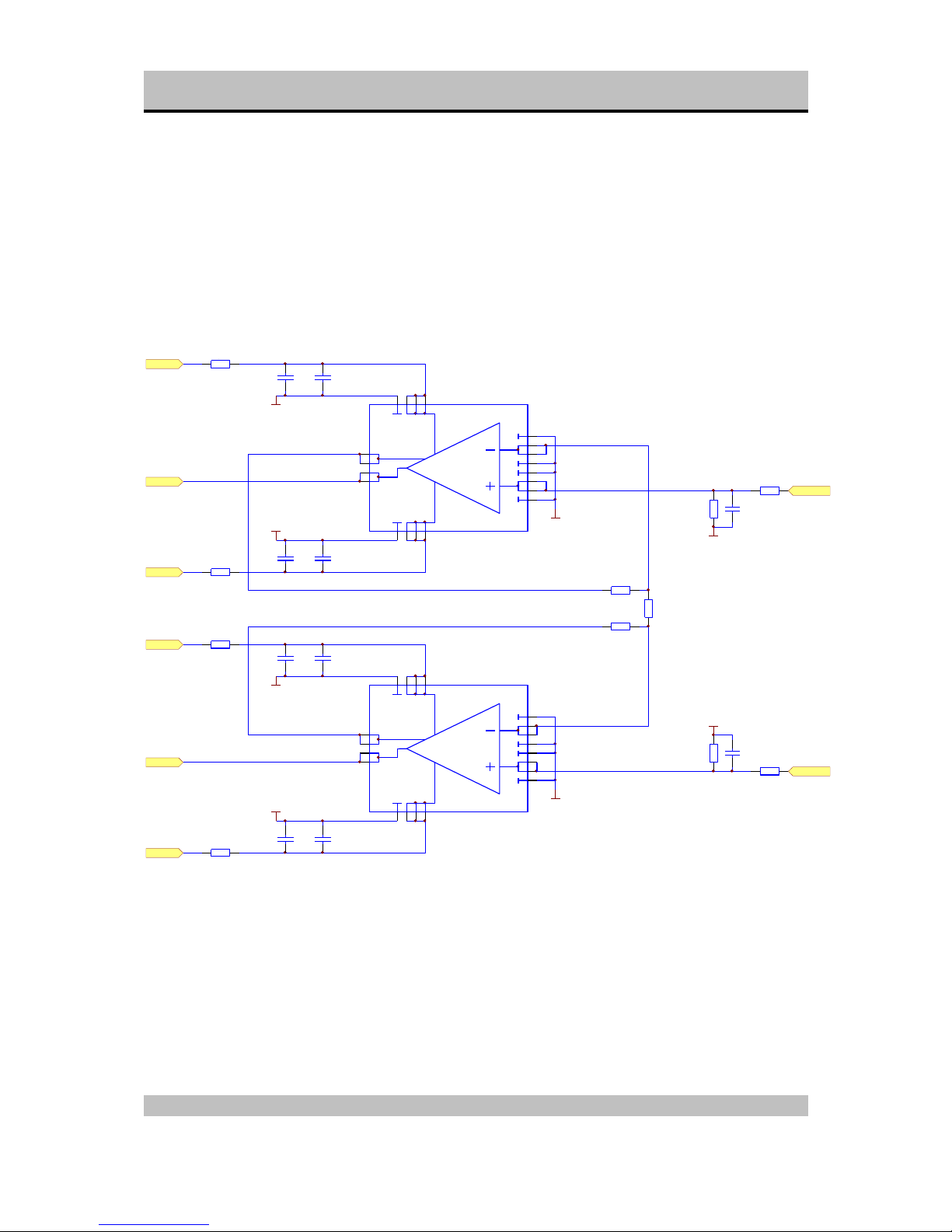
Figure 15: Left Output Amp
4
3
2
1
5
6
7
8
121110
9
171819
20
14
15
16
13
+V
-V
OUT
NFB
U10
DISAMPMODULE
4
3
2
1
5
6
7
8
121110
9
171819
20
14
15
16
13
+V
-V
OUT
NFB
U11
DISAMPMODULE
AGND
+
C52
C63V/2200U
+
C49
C63V/2200U
+
C48
C63V/2200U
+
C45
C63V/2200U
AGND
AGND
AGND
AGND
R54
1R00
R55
1R00
R56
1R00
R57
1R00
L+24V
L-24V
L+24V
L-24V
+L-OUT
-L-OUT
R64
10K0 .1%
R63
10K0 .1%
R67
10K0 .1%
R70
100K
R71
100K
AGND
AGND
R74
2x0.3 zilver
R75
2x0.3 zilver
-LV-OUT
+LV-OUT
AGND
C46
47N/PP
C47
47N/PP
C50
47N/PP
C51
47N/PP
37..40mA
37..40mA
37..40mA
37..40mA
C61
220p
C62
220p
Page 27
SPHINX Project Eight Service Manual
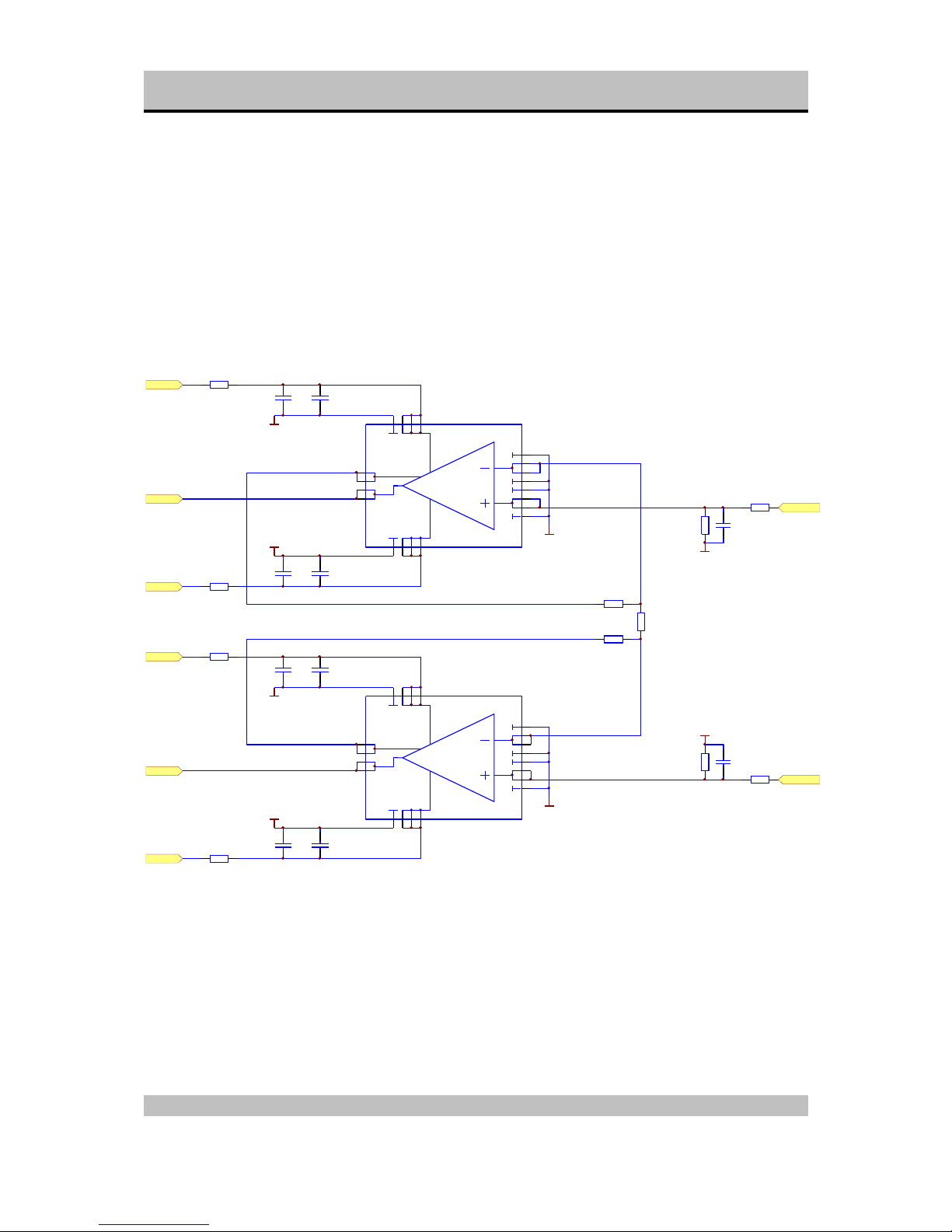
27
Figure 16: Right Output Amp
4
3
2
1
5
6
7
8
121110
9
171819
20
14
15
16
13
+V
-V
OUT
NFB
U12
DISAMPMODULE
4
3
2
1
5
6
7
8
121110
9
171819
20
14
15
16
13
+V
-V
OUT
NFB
U13
DISAMPMODULE
AGND
+ C59
C63V/2200U
+ C60
C63V/2200U
+ C56
C63V/2200U
+ C53
C63V/2200U
AGND
AGND
AGND
AGND
R58
1R00
R59
1R00
R60
1R00
R61
1R00
R+24V
R-24V
R+24V
R-24V
+R-OUT
-R-OUT
R66
10K0 .1%
R65
10K0 .1%
R68
10K0 .1%
R72
100K
R73
100K
AGND
AGND
R76
2x0.3 zilver
R77
2x0.3 zilver
-RV-OUT
+RV-OUT
AGND
C54
47N/PP
C55
47N/PP
C57
47N/PP
C58
47N/PP
37..40mA
37..40mA
37..40mA
37..40mA
C63
220p
C64
220p
Page 28

SPHINX Project Eight Service Manual
28
Figure 17: Left Input Amp
4
3
2
1
5
6
7
8
121110
9
171819
20
14
15
16
13
+V
-V
OUT
NFB
U22
DISAMPMODULE
4
3
2
1
5
6
7
8
121110
9
171819
20
14
15
16
13
+V
-V
OUT
NFB
U23
DISAMPMODULE
AGND
+ C113
C63V/2200U
+ C110
C63V/2200U
+ C109
C63V/2200U
+ C106
C63V/2200U
AGND
AGND
AGND
AGND
R150
1R00
R151
1R00
R152
1R00
R153
1R00
L+24V
L-24V
L+24V
L-24V
+LV-IN
-LV-IN
R160
20K0 .1%
R158
10K0 .1%
R159
10K0 .1%
R166
50K0
R167
50K0
C122
220p
C123
220p
AGND
AGND
R170
1K00
R171
1K00
-L-IN
+L-IN
R161
20K0 .1%
+
RL59
REL16
+24VCINCH
AGND
C107
47N/PP
C108
47N/PP
C111
47N/PP
C112
47N/PP
37..40mA
37..40mA
37..40mA
37..40mA
Page 29

SPHINX Project Eight Service Manual
29
Figure 18: Right Input Amp
4
3
2
1
5
6
7
8
121110
9
171819
20
14
15
16
13
+V
-V
OUT
NFB
U24
DISAMPMODULE
4
3
2
1
5
6
7
8
121110
9
171819
20
14
15
16
13
+V
-V
OUT
NFB
U25
DISAMPMODULE
AGND
+ C121
C63V/2200U
+ C118
C63V/2200U
+ C117
C63V/2200U
+ C114
C63V/2200U
AGND
AGND
AGND
AGND
R154
1R00
R155
1R00
R156
1R00
R157
1R00
R+24V
R-24V
R+24V
R-24V
+RV-IN
-RV-IN
R164
20K0 .1%
R162
10K0 .1%
R163
10K0 .1%
R168
50K0
R169
50K0\
C124
220p
C125
220p
AGND
AGND
R172
1K00
R173
1K00
-R-IN
+R-IN
R165
20K0 .1%
+
RL60
REL16
+24VCINCH
AGND
C115
47N/PP
C116
47N/PP
C119
47N/PP
C120
47N/PP
37..40mA
37..40mA
37..40mA
37..40mA
Page 30
SPHINX Project Eight Service Manual
30
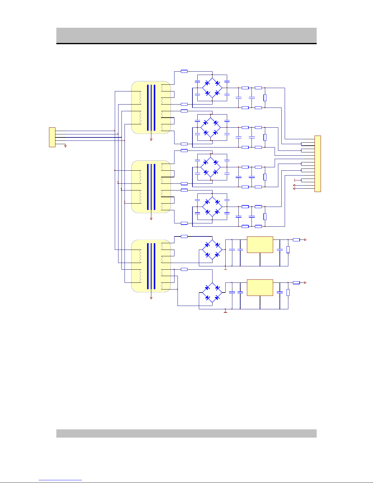
Figure 19: Power Supply Unit
C1
C2
C3
C4
B1
BRIDGE6
C7
C8
C9
C10
B2
BRIDGE6
B5
BRIDGE6
1R
R2
1R
R8
1R
R9
1R
R29
1R
+
C25
C63V/2200U
+
C5
C50V/6800U
+
C11
C50V/6800U
+
C12
C50V/6800U
+
C6
C50V/6800U
R31RR4
1R
R51RR6
1R
R101RR11
1R
R121RR13
1R
VoutVin
GND
U1
7824
C26
C13
C14
C15
C16
B3
BRIDGE6
C19
C20
C21
C22
B4
BRIDGE6
B6
BRIDGE6
R15
1R
R16
1R
R22
1R
R23
1R
R30
1R
+
C28
C63V/2200U
+
C17
C50V/6800U
+
C23
C50V/6800U
+
C24
C50V/6800U
+
C18
C50V/6800U
R171RR18
1R
R191RR20
1R
R241RR25
1R
R261RR27
1R
VoutVin
GND
U2
7809
C29
+9V
+24V
DGND
1
2
3
4
5
6
7
8
9
10
11
12
13
14
15
16
CN1
16PIN
+9V
+24V
DGND
+
C27
C50V/330U
+
C30
C50V/330U
R21
10K0
R28
10K0
R14
10K0
R7
10K0
R32
1R
14V
14V
14V
14V
120V
120V
T1
R-CORE 50VA
14V
14V
14V
14V
120V
120V
T2
R-CORE 50VA
PE
PE
14V
14V
14V
14V
120V
120V
T3
R-CORE 50VA
DGND
R33
1R
PE
38..32 Volt
18..15 Volt
R34
10K0
R35
10K0
1
2
3
4
5
CN2
5PIN
PE
Page 31

SPHINX Project Eight Service Manual
31
Figure 20: PCB drawings
Because there is a significant image-quality loss during the conversion of the drawings, The PCB-drawings are
located in separate files.
These files are in PDF-format (Adobé Acrobat 3.0 Reader)
Project 8 mainboard (A3 format)
“PJ-8A3mainboard.pdf”
Project 8 mainboard (A4 format)
“PJ-8A4mainboard.pdf”
Project 8 Disamp Module (A4 format)
“Pj-8disamp.pdf”
Project 8 Display Module (A4 format)
“Pj-8display.pdf”
Project 8 Power Supply (A4 format)
“Pj-8powersupply.pdf”
Page 32

SPHINX Project Eight Service Manual
32
Parts List
Designator Part Type Description
B1 BRIDGE6 Bridge rectifier
B2 BRIDGE6 Bridge rectifier
B3 BRIDGE6 Bridge rectifier
B4 BRIDGE6 Bridge rectifier
B5 BRIDGE6 Bridge rectifier
B6 BRIDGE6 Bridge rectifier
C1 100NMKT Capacitor
C1 330N/PP Capacitor
C1 33p Capacitor
C1 47n Capacitor
C10 100NMKT Capacitor
C10 C25V/47U Capacitor
C10 C63V/1000U Capacitor
C100 100NMKT Capacitor
C101 100NMKT Capacitor
C102 100NMKT Capacitor
C103 100NMKT Capacitor
C104 100NMKT Capacitor
C105 100NMKT Capacitor
C106 C63V/2200U Capacitor
C107 47N/PP Capacitor
C108 47N/PP Capacitor
C109 C63V/2200U Capacitor
C11 C25V/47U Capacitor
C11 C50V/6800U Capacitor
C11 C63V/1000U Capacitor
C110 C63V/2200U Capacitor
C111 47N/PP Capacitor
C112 47N/PP Capacitor
C113 C63V/2200U Capacitor
C114 C63V/2200U Capacitor
C115 47N/PP Capacitor
C116 47N/PP Capacitor
C117 C63V/2200U Capacitor
C118 C63V/2200U Capacitor
C119 47N/PP Capacitor
C12 330N/PP Capacitor
C12 C25V/47U Capacitor
C12 C50V/6800U Capacitor
C120 47N/PP Capacitor
C121 C63V/2200U Capacitor
C122 220p Capacitor
C123 220p Capacitor
C124 220p Capacitor
C125 220p Capacitor
C13 100NMKT Capacitor
C13 C50V/330U Capacitor
C14 100NMKT Capacitor
C14 47N/PP Capacitor
C15 100NMKT Capacitor
C15 47N/PP Capacitor
C16 100NMKT Capacitor
C16 C50V/330U Capacitor
C17 C50V/330U Capacitor
C17 C50V/6800U Capacitor
C18 47N/PP Capacitor
C18 C50V/6800U Capacitor
C19 100NMKT Capacitor
C19 47N/PP Capacitor
C2 100NMKT Capacitor
C2 33p Capacitor
C2 47n Capacitor
Page 33

SPHINX Project Eight Service Manual
33
Designator Part Type Description
C2 C63V/1000U Capacitor
C20 100NMKT Capacitor
C20 C50V/330U Capacitor
C21 100NMKT Capacitor
C21 330N/PP Capacitor
C22 100NMKT Capacitor
C22 330N/PP Capacitor
C23 330N/PP Capacitor
C23 C50V/6800U Capacitor
C24 330N/PP Capacitor
C24 C50V/6800U Capacitor
C25 22N/PP Capacitor
C25 C63V/2200U Capacitor
C26 100NMKT Capacitor
C26 C50V/330U Capacitor
C27 C50V/330U Capacitor
C27 C50V/330U Capacitor
C28 22N/PP Capacitor
C28 C63V/2200U Capacitor
C29 100NMKT Capacitor
C29 22N/PP Capacitor
C3 100NMKT Capacitor
C3 220n Capacitor
C3 470pF Capacitor
C3 C63V/1000U Capacitor
C30 C50V/330U Capacitor
C30 C50V/330U Capacitor
C31 C50V/330U Capacitor
C32 22N/PP Capacitor
C33 C63V/2200U Capacitor
C34 22N/PP Capacitor
C35 C50V/330U Capacitor
C36 C50V/330U Capacitor
C37 22N/PP Capacitor
C38 C63V/2200U Capacitor
C39 C63V/2200U Capacitor
C4 100NMKT Capacitor
C4 220n Capacitor
C4 47pF Capacitor
C4 C63V/1000U Capacitor
C40 22N/PP Capacitor
C41 C50V/330U Capacitor
C42 C50V/330U Capacitor
C43 22N/PP Capacitor
C44 C63V/2200U Capacitor
C45 C63V/2200U Capacitor
C46 47N/PP Capacitor
C47 47N/PP Capacitor
C48 C63V/2200U Capacitor
C49 C63V/2200U Capacitor
C5 10n Capacitor
C5 220n Capacitor
C5 C50V/6800U Capacitor
C5 C63V/1000U Capacitor
C50 47N/PP Capacitor
C51 47N/PP Capacitor
C52 C63V/2200U Capacitor
C53 C63V/2200U Capacitor
C54 47N/PP Capacitor
C55 47N/PP Capacitor
C56 C63V/2200U Capacitor
C57 47N/PP Capacitor
C58 47N/PP Capacitor
C59 C63V/2200U Capacitor
C6 10n Capacitor
C6 220n Capacitor
C6 330N/PP Capacitor
C6 C50V/6800U Capacitor
C60 C63V/2200U Capacitor
Page 34

SPHINX Project Eight Service Manual
34
Designator Part Type Description
C61 220p Capacitor
C62 220p Capacitor
C63 220p Capacitor
C64 220p Capacitor
C65 100NMKT Capacitor
C66 100NMKT Capacitor
C67 100NMKT Capacitor
C68 100NMKT Capacitor
C69 100NMKT Capacitor
C7 100NMKT Capacitor
C7 330N/PP Capacitor
C7 3U3/63V Capacitor
C7 C25V/47U Capacitor
C70 100NMKT Capacitor
C71 100NMKT Capacitor
C72 100NMKT Capacitor
C73 100NMKT Capacitor
C74 C50V/330U Capacitor
C75 100NMKT Capacitor
C76 100NMKT Capacitor
C77 100NMKT Capacitor
C78 100NMKT Capacitor
C79 100NMKT Capacitor
C8 100NMKT Capacitor
C8 C25V/47U Capacitor
C8 C47U/16V Capacitor
C8 C63V/1000U Capacitor
C80 100NMKT Capacitor
C81 100NMKT Capacitor
C82 100NMKT Capacitor
C83 100NMKT Capacitor
C84 100NMKT Capacitor
C85 100NMKT Capacitor
C86 100NMKT Capacitor
C87 100NMKT Capacitor
C88 100NMKT Capacitor
C89 100NMKT Capacitor
C9 100NMKT Capacitor
C9 470U/16V Capacitor
C9 C25V/47U Capacitor
C9 C63V/1000U Capacitor
C90 100NMKT Capacitor
C91 100NMKT Capacitor
C92 100NMKT Capacitor
C93 C50V/330U Capacitor
C94 100NMKT Capacitor
C95 100NMKT Capacitor
C96 100NMKT Capacitor
C97 100NMKT Capacitor
C98 100NMKT Capacitor
C99 100NMKT Capacitor
CN1 16PIN Connector
CN1 18PIN Connector
CN1 4PIN Connector
CN1 KAST_GND Connector
CN1 XLR MALE Connector
CN10 CINCH Connector
CN11 CINCH Connector
CN12 CINCH Connector
CN13 CINCH Connector
CN14 CINCH Connector
CN15 CINCH Connector
CN16 CINCH Connector
CN17 CINCH Connector
CN18 CINCH Connector
CN19 CINCH Connector
CN2 20PIN Connector
Page 35

SPHINX Project Eight Service Manual
35
Designator Part Type Description
CN2 4PIN Connector
CN2 5PIN Connector
CN2 XLR MALE Connector
CN20 CINCH Connector
CN21 XLR FEMALE Connector
CN22 XLR FEMALE Connector
CN23 XLR FEMALE Connector
CN24 XLR FEMALE Connector
CN3 4PIN Connector
CN3 XLR MALE Connector
CN4 8PIN Connector
CN4 XLR MALE Connector
CN5 CINCH Connector
CN6 CINCH Connector
CN7 CINCH Connector
CN8 CINCH Connector
CN9 CINCH Connector
D1 1N4004 Diode
D1 1N4148 Diode
D1 1N4148 Diode
D10 1N4148 Diode
D11 1N4148 Diode
D12 1N4148 Diode
D2 1N4004 Diode
D2 1N4148 Diode
D3 1N4004 Diode
D3 1N4148 Diode
D4 1N4004 Diode
D4 1N4148 Diode
D5 1N4004 Diode
D6 1N4004 Diode
D7 1N4004 Diode
D8 1N4004 Diode
D9 1N4148 Diode
IR1 IRIC Infrared receiver
J1 Jumper R Jumper
J2 Jumper R Jumper
J3 Jumper R Jumper
LD1 LD RD LED
LD1 LD RD LED
LD2 LD RD LED
LD2 LD RD LED
LD3 LD RD LED
LD3 LD RD LED
LD4 LD RD LED
LD4 LD RD LED
LD5 LD RD LED
LD6 LD RD LED
OPT1 OPTOUT optical output
OPT2 OPTOUT optical output
OPT3 OPTOUT optical output
P1 50R Var. Resistor
P2 50R Var. Resistor
R1 100R Resistor
R1 1R Resistor
Page 36

SPHINX Project Eight Service Manual
36
Designator Part Type Description
R1 27K4 Resistor
R1 4k75 Resistor
R10 1R Resistor
R10 1R00 Resistor
R10 4K75 Resistor
R100 20K0 Resistor
R101 80R6 Resistor
R102 10K0 Resistor
R103 40R2 Resistor
R104 10K0 Resistor
R105 40R2 Resistor
R106 10K0 Resistor
R107 40R2 Resistor
R108 10K0 Resistor
R109 40R2 Resistor
R11 15R0 Resistor
R11 1R Resistor
R11 600R Resistor
R110 5K23 Resistor
R111 20R0 Resistor
R112 5K23 Resistor
R113 20R0 Resistor
R114 5K23 Resistor
R115 20R0 Resistor
R116 5K23 Resistor
R117 20R0 Resistor
R118 2K61 Resistor
R119 10R0 Resistor
R12 15R0 Resistor
R12 1R Resistor
R12 600R Resistor
R120 2K61 Resistor
R121 10R0 Resistor
R122 2K61 Resistor
R123 10R0 Resistor
R124 2K61 Resistor
R125 10R0 Resistor
R126 1K30 Resistor
R127 0R00 Resistor
R128 1K30 Resistor
R129 0R00 Resistor
R13 18R0 Resistor
R13 1R Resistor
R13 1R00 Resistor
R130 1K30 Resistor
R131 0R00 Resistor
R132 1K30 Resistor
R133 0R00 Resistor
R134 649R Resistor
R135 634K Resistor
R136 649R Resistor
R137 634K Resistor
R138 649R Resistor
R139 634K Resistor
R14 10K0 Resistor
R14 18R0 Resistor
R14 1R00 Resistor
R140 649R Resistor
R141 634K Resistor
R142 2K00 Resistor
R143 2K00 Resistor
R144 2K00 Resistor
R145 2K00 Resistor
R146 2K00 Resistor
R147 2K00 Resistor
R148 2K00 Resistor
R149 2K00 Resistor
R15 10R0 Resistor
R15 15R0 Resistor
Page 37

SPHINX Project Eight Service Manual
37
Designator Part Type Description
R15 1R Resistor
R150 1R00 Resistor
R151 1R00 Resistor
R152 1R00 Resistor
R153 1R00 Resistor
R154 1R00 Resistor
R155 1R00 Resistor
R156 1R00 Resistor
R157 1R00 Resistor
R158 10K0 .1% Resistor
R159 10K0 .1% Resistor
R16 1R Resistor
R16 2K21 Resistor
R16 332R Resistor
R160 20K0 .1% Resistor
R161 20K0 .1% Resistor
R162 10K0 .1% Resistor
R163 10K0 .1% Resistor
R164 20K0 .1% Resistor
R165 20K0 .1% Resistor
R166 50K0 Resistor
R167 50K0 Resistor
R168 50K0 Resistor
R169 50K0 Resistor
R17 10K0 Resistor
R17 1R Resistor
R17 51R0 Resistor
R170 1K00 Resistor
R171 1K00 Resistor
R172 1K00 Resistor
R173 1K00 Resistor
R174 10R0 Resistor
R175 33K2 Resistor
R176 33K2 Resistor
R18 1R Resistor
R18 2K00 Resistor
R18 2K21 Resistor
R19 1R Resistor
R19 2K00 Resistor
R19 2K21 Resistor
R2 10K0 Resistor
R2 1R Resistor
R2 243R Resistor
R2 4k75 Resistor
R20 1R Resistor
R20 2K00 Resistor
R20 2K21 Resistor
R21 10K0 Resistor
R21 10K0 Resistor
R21 2K21 Resistor
R22 1R Resistor
R22 332R Resistor
R22 51R0 Resistor
R23 10K0 Resistor
R23 1R Resistor
R23 2K21 Resistor
R24 1R Resistor
R24 200R Resistor
R24 2K00 Resistor
R25 1R Resistor
R25 200R Resistor
R25 2K00 Resistor
R26 100R Resistor
R26 1R Resistor
R26 2K00 Resistor
R27 100R Resistor
R27 10K0 Resistor
R27 1R Resistor
R28 100R Resistor
Page 38

SPHINX Project Eight Service Manual
38
Designator Part Type Description
R28 10K0 Resistor
R28 332R Resistor
R29 1R Resistor
R29 243R Resistor
R29 332R Resistor
R3 1R Resistor
R3 4k75 Resistor
R3 51R0 Resistor
R3 5R62 Resistor
R30 1R Resistor
R30 200R Resistor
R30 2K00 Resistor
R31 100R Resistor
R31 2K00 Resistor
R32 100K Resistor
R32 1R Resistor
R32 200R Resistor
R33 1R Resistor
R33 243R Resistor
R33 3K32 Resistor
R34 10K0 Resistor
R34 33K2 Resistor
R34 3K32 Resistor
R35 10K0 Resistor
R35 3K32 Resistor
R36 3K32 Resistor
R37 8K25 Resistor
R38 8K25 Resistor
R39 8K25 Resistor
R4 10R0 Resistor
R4 1R Resistor
R4 22K1 Resistor
R4 61K9 Resistor
R40 8K25 Resistor
R41 1R00 Resistor
R42 1R00 Resistor
R43 1R00 Resistor
R44 1R00 Resistor
R45 10K0 Resistor
R46 1K00 Resistor
R47 1K00 Resistor
R48 10K0 Resistor
R49 10K0 Resistor
R5 1R Resistor
R5 22K1 Resistor
R5 24R9 Resistor
R5 68K1 Resistor
R50 1K00 Resistor
R51 1K00 Resistor
R52 10K0 Resistor
R53 100K Resistor
R54 1R00 Resistor
R55 1R00 Resistor
R56 1R00 Resistor
R57 1R00 Resistor
R58 1R00 Resistor
R59 1R00 Resistor
R6 10R0 Resistor
R6 1R Resistor
R6 22K1 Resistor
R60 1R00 Resistor
R61 1R00 Resistor
R62 100K Resistor
R63 10K0 .1% Resistor
R64 10K0 .1% Resistor
R65 10K0 .1% Resistor
R66 10K0 .1% Resistor
R67 10K0 .1% Resistor
R68 10K0 .1% Resistor
Page 39

SPHINX Project Eight Service Manual
39
Designator Part Type Description
R69 100K Resistor
R7 10K0 Resistor
R7 22K1 Resistor
R7 51R0 Resistor
R70 100K Resistor
R71 100K Resistor
R72 100K Resistor
R73 100K Resistor
R74 2x0.3 silver Resistor
R75 2x0.3 zilver Resistor
R76 2x0.3 zilver Resistor
R77 2x0.3 zilver Resistor
R78 84K5 Resistor
R79 324R Resistor
R8 15R0 Resistor
R8 1R Resistor
R8 243R Resistor
R80 84K5 Resistor
R81 324R Resistor
R82 84K5 Resistor
R83 324R Resistor
R84 84K5 Resistor
R85 324R Resistor
R86 39K2 Resistor
R87 162R Resistor
R88 39K2 Resistor
R89 162R Resistor
R9 100R Resistor
R9 1R Resistor
R9 1R00 Resistor
R90 39K2 Resistor
R91 162R Resistor
R92 39K2 Resistor
R93 162R Resistor
R94 20K0 Resistor
R95 80R6 Resistor
R96 20K0 Resistor
R97 80R6 Resistor
R98 20K0 Resistor
R99 80R6 Resistor
RL1 REL16 Relay 24V
RL10 REL16 Relay 24V
RL11 REL16 Relay 24V
RL12 REL16 Relay 24V
RL13 REL16 Relay 24V
RL14 REL16 Relay 24V
RL15 REL16 Relay 24V
RL16 REL16 Relay 24V
RL17 REL16 Relay 24V
RL18 REL16 Relay 24V
RL19 REL16 Relay 24V
RL2 REL16 Relay 24V
RL20 REL16 Relay 24V
RL21 REL16 Relay 24V
RL22 REL16 Relay 24V
RL23 REL16 Relay 24V
RL24 REL16 Relay 24V
RL25 REL16 Relay 24V
RL26 REL16 Relay 24V
RL27 REL16 Relay 24V
RL28 REL16 Relay 24V
RL29 REL16 Relay 24V
RL3 REL16 Relay 24V
RL30 REL16 Relay 24V
RL31 REL16 Relay 24V
RL32 REL16 Relay 24V
Page 40

SPHINX Project Eight Service Manual
40
Designator Part Type Description
RL33 REL16 Relay 24V
RL34 REL16 Relay 24V
RL35 REL16 Relay 24V
RL36 REL16 Relay 24V
RL37 REL16 Relay 24V
RL38 REL16 Relay 24V
RL39 REL16 Relay 24V
RL4 REL16 Relay 24V
RL40 REL16 Relay 24V
RL41 REL16 Relay 24V
RL42 REL16 Relay 24V
RL43 REL16 Relay 24V
RL44 REL16 Relay 24V
RL45 REL16 Relay 24V
RL46 REL16 Relay 24V
RL47 REL16 Relay 24V
RL48 REL16 Relay 24V
RL49 REL16 Relay 24V
RL5 REL16 Relay 24V
RL50 REL16 Relay 24V
RL51 REL16 Relay 24V
RL52 REL16 Relay 24V
RL53 REL16 Relay 24V
RL54 REL16 Relay 24V
RL55 REL16 Relay 24V
RL56 REL16 Relay 24V
RL57 REL16 Relay 24V
RL58 REL16 Relay 24V
RL59 REL16 Relay 24V
RL6 REL16 Relay 24V
RL60 REL16 Relay 24V
RL7 REL16 Relay 24V
RL8 REL16 Relay 24V
RL9 REL16 Relay 24V
S1 ENCOD Encoder
S2 ENCOD Encoder
S3 DRUK-TOETS Switch
S4 DRUK-TOETS Switch
S5 DRUK-TOETS Switch
SP1 SILPAD Soldering pad
SP10 SILPAD Soldering pad
SP11 SILPAD Soldering pad
SP12 SILPAD Soldering pad
SP13 SILPAD Soldering pad
SP14 SILPAD Soldering pad
SP15 SILPAD Soldering pad
SP16 SILPAD Soldering pad
SP2 SILPAD Soldering pad
SP3 SILPAD Soldering pad
SP4 SILPAD Soldering pad
SP5 SILPAD Soldering pad
SP6 SILPAD Soldering pad
SP7 SILPAD Soldering pad
SP8 SILPAD Soldering pad
SP9 SILPAD Soldering pad
T1 R-CORE 50VA Transformer
T2 R-CORE 50VA Transformer
T3 R-CORE 50VA Transformer
T1 A1306 Transistor
T1 C3298 Transistor
Page 41

SPHINX Project Eight Service Manual
41
Designator Part Type Description
T2 C2240 Transistor
T2 C3298 Transistor
T3 A1145 Transistor
T3 A1306 Transistor
T4 C2705 Transistor
T4 C3298 Transistor
T5 A1145 Transistor
T5 A970 Transistor
T6 A1306 Transistor
T6 C2705 Transistor
T7 C2240 Transistor
T7 C3298 Transistor
T8 A970 Transistor
T8 C2240 Transistor
T9 A1306 Transistor
T9 K389 Transistor
T10 C3298 Transistor
T10 J109 Transistor
T11 A970 Transistor
T11 C2240 Transistor
T12 A1306 Transistor
T12 A970 Transistor
T13 A970 Transistor
T13 A970 Transistor
T14 C2240 Transistor
T14 C2240 Transistor
T15 A970 Transistor
T16 C2240 Transistor
U1 7824 Stab. IC
U2 7809 Stab. IC
U20 MC7805T Stab. IC
U1 16PIN Connector
U1 H8/325 Microprocessor
U10 DISAMPMODULE DISCRETE OPAMP MODULE
U11 DISAMPMODULE DISCRETE OPAMP MODULE
U12 DISAMPMODULE DISCRETE OPAMP MODULE
U13 DISAMPMODULE DISCRETE OPAMP MODULE
U14 UCN5801 Driver IC
U15 UCN5801 Driver IC
U16 UCN5801 Driver IC
U17 UCN5801 Driver IC
U18 UCN5801 Driver IC
U21 UCN5801 Driver IC
U19 18PIN Connector
U2 MAX690 Reset IC
U2 OP604 Opamp
U3 OP604 Opamp
U4 OP604 Opamp
U5 OP604 Opamp
U22 DISAMPMODULE DISCRETE OPAMP MODULE
U23 DISAMPMODULE DISCRETE OPAMP MODULE
U24 DISAMPMODULE DISCRETE OPAMP MODULE
U25 DISAMPMODULE DISCRETE OPAMP MODULE
U3 8M X-TAL
U4 93C46 EEPROM
U6 LM329DZ ZENER Diode
Page 42

SPHINX Project Eight Service Manual
42
Designator Part Type Description
U7 LM329DZ ZENER Diode
U8 LM329DZ ZENER Diode
U9 LM329DZ ZENER Diode
©1998 Audioscript BV
Version: May 13, 1998
 Loading...