

Page 1
SERVICE MANUAL
PROJECT TWO Mk2
PRE-AMP
Page 2

SPHINX Project Two Mk2 Service Manual
1. UNPACKING.......................................................................................................................................3
2. SPHINX WARRANTY CARD..............................................................................................................3
3. CONTACTING THE MANUFACTURER.............................................................................................3
4. THE PRE-AMP AT A GLANCE ..........................................................................................................4
Front panel................................................................................................................................................... 4
Rear panel ...................................................................................................................................................5
5. OPERATION .......................................................................................................................................6
Power on...................................................................................................................................................... 6
Selecting an input ........................................................................................................................................6
Adjusting the volume level ...........................................................................................................................6
Memory mode..............................................................................................................................................6
Power off...................................................................................................................................................... 6
6. SPHINX REMOTE CONTROL............................................................................................................7
Buttons and LED indication..........................................................................................................................7
Operation.....................................................................................................................................................8
Selecting without switching..........................................................................................................................8
Batteries.......................................................................................................................................................8
Encountering problems................................................................................................................................8
7. TECHNICAL SPECIFICATIONS.........................................................................................................9
8. ADJUSTMENT PROCEDURES........................................................................................................10
Bias and Offset ..........................................................................................................................................10
Initial Set-up...............................................................................................................................................10
Bias / Offset Adjustment ............................................................................................................................10
9. PROBLEMS AND SOLUTIONS .......................................................................................................11
10. DIAGRAMS AND PARTS LISTS....................................................................................................12
Connection Diagram for testing the Project 2 Mk2.....................................................................................13
Schematic overview of Project 2 mainboard..............................................................................................14
Project 2 power supply overview................................................................................................................15
Project 2 power supply...............................................................................................................................16
Project 2 input selection.............................................................................................................................17
Project 2 left pre-amp.................................................................................................................................18
Project 2 right pre-amp ..............................................................................................................................19
Project 2 phase inverter.............................................................................................................................20
Project 2 display.........................................................................................................................................21
PCB drawings of Project 2 Mk2 .................................................................................................................22
Partlist pre-amp..........................................................................................................................................23
Partlist display............................................................................................................................................31
2
Page 3

SPHINX Project Two Mk2 Service Manual
The Sphinx Project Two Mk2 design principles
The Sphinx Project Two Mk2 was designed for the
ever-increasing group of quality-conscious
audiophiles.
We are very proud of the tradition connected with
the SPHINX name, especially concerning audio
quality perfection.
This service manual will help you to optimally
service and repair the Sphinx Project Two Mk2 PreAmp.
This pre-amp is extremely simple to operate and
uses the newest technologies and refined designs.
Designs that have successfully been used in the
award winning Project Eight.
Features include ultra-linear extremely low-noise
Class A audio circuits, built from the finest handselected parts.
The signal path is completely balanced from input to
output, and left and right are totally separated.
The power supply is of a unique design (fully ClassA!) and consists of three completely separate and
independent sections: one for the digital control plus
one each for the left and right channel.
The ALPS volume control is motor-controlled.
All settings and controls can also be accessed from
the supplied Sphinx Remote Control.
1. UNPACKING
Before leaving the factory every Project Two Mk2 is
subjected to stringent and extensive technical and
exterior quality inspection. This ensures the user
many years of high quality audio from a perfectlooking product.
We recommend owners to ship the Project Two
Mk2 in its original carton.
After unpacking the Project Two Mk2 we therefore
recommend you carefully check it for any transport
damage.
If you find any damage and the product has not
been shipped in the original carton the ensuring
repair costs will not be covered by the warranty.
2. SPHINX WARRANTY CARD
To be entitled to any warranty repairs the owner
must have send the filled out warranty card to
Sphinx or a distributor where it has been registered.
Other regulations may apply in your specific
country: when in doubt, please consult the proper
authorities.
To obtain the maximum quality from this pre amp it
is necessary for it to be properly aligned and to be
used with top quality audio components, preferably
other Sphinx components.
Please also refer to the User Manual of the
Project Two Mk2 for information about
functions not described in this manual.
It is important to familiarise yourself with the
special functions, operation and possibilities
of the Sphinx Project Two Mk2.
3. CONTACTING THE MANUFACTURER
In case of any problem not covered in this manual
or if you have other questions you may contact the
Sphinx International Service Department in The
Netherlands (local time: GMT +1h) during office
hours at the following numbers:
Telephone (+31) 35 602 0302
Fax (+31) 35 602 2806
E-mail audionl@euronet.nl
It is always very helpful and efficient if you have all
relevant information about the specific product and
the problem ready.
3
Page 4

SPHINX Project Two Mk2 Service Manual
4. THE PRE-AMP AT A GLANCE
Front panel
1
1 2
1. INPUT: With this rotary knob you may select
one of the six inputs.
Turn clockwise for an input to the right of the
active one, anti-clockwise for an input to the
left.
2. STANDBY: To switch the component on and
off:
on LED is green
off LED is red
3. Receptor window for the IR signals from the
Remote Control.
4. Input selection LED's: The input selected with
knob (1.) is indicated by one of these LED's:
CD SYM balanced CD input
CD unbalanced CD input
TUNER unbalanced Tuner input
LINE 1 unbalanced line input 1
LINE 2 unbalanced line input 2
LINE 3 unbalanced line input 3.
3 5
4 6 7 8
5. MUTE: Press this button to temporarily mute
the sound. The red LED will light.
6. TAPE MON: To select the TAPE IN input. The
red LED will light.
7. PHONES: To connect dynamic stereo
headphones.
8. VOLUME: This rotary knob adjusts the volume
level.
4
Page 5

SPHINX Project Two Mk2 Service Manual
25
26
Rear panel
9 10 11 12 13 14 15 16 17 18 19 20 21 22 23 24
9. GROUND: You may directly connect the signal
grounds of other equipment to the signal
ground of the Project Two Mk2.
10. TAPE OUT: Connect this output to the input of
the recorder.
11. TAPE IN: Connect this input to the output of
the recorder.
12. CD: To connect the cinch signal cable from the
CD player.
13. TUNER: To connect the cinch signal cable from
the tuner.
14. LINE 1: To connect the cinch signal cable from
the signal source for LINE 1.
15. LINE 2: To connect the cinch signal cable from
the signal source for LINE 2.
16. LINE 3: To connect the cinch signal cable from
the signal source for LINE 3.
17. CD BALANCED L: To connect the XLR signal
cable (balanced cable) from the left output of
the CD player.
18. CD BALANCED R: To connect the XLR signal
cable (balanced cable) from the right output of
the CD player.
19. BALANCED OUT L: To connect the XLR
signal cable (balanced cable) from the left input
of the power amp.
20. BALANCED OUT R: To connect the XLR
signal cable (balanced cable) from the right
input of the power amp.
21. OUT 1 L+R: Connect this output with a cinch
signal cable to the input of your power amp.
22. OUT 2 L+R: To connect the XLR signal cable
(balanced cable) from the right input of the
extra power amp or surround processor.
23. Control Out: To connect the optical cable
going to another Sphinx component.
24. Warning!: This shows important information
about the safety regulations for the
Project Two Mk2.
25. AC Power: Connect the mains cable to a
mains power outlet (230 - 240 VAC).
26. O / I: This is the mains power switch.
27. Fuse holder: Contains a fuse (500 mA slow).
28. Selector for power supply voltage (120/240
V), (115/230 V).
27 28
5
Page 6

SPHINX Project Two Mk2 Service Manual
5. OPERATION
Connect the mains cable to a mains outlet.
Once you have finished connecting all components,
you can power on the Project Two Mk2 with the
mains switch O / I (26.).
The volume control will then automatically turn
counter-clockwise and, for a while, the STANDBY
LED will blink red/green, after which it will remain
red.
The pre-amp is now in standby mode.
Power on
You switch the amp on with the STANDBY button.
That way, all circuits will remain at optimum
operating temperatures and the audio quality will be
100% immediately after switching on. Additionally it
significantly increases the life span of the
component.
The pre-amp will select the CD SYM input after
which it un-mutes the output.
Selecting an input
You select the input with the large rotary knob
INPUT:
clockwise to the right of the selected one,
anti-clockwise to the left of the selected one.
Upon reaching LINE 3 or CD SYM you cannot 'roll
over' to CD SYM or LINE 3 respectively.
As long as you move the knob, only the LED's will
change: the current selected input remains active.
The new input only becomes active after you have
selected it and released the INPUT knob.
You will hear a 'click'. This is caused by the precision
relays for the inputs: the 'old' one is released while
the new one is energised.
Adjusting the volume level
The large VOLUME control to the right adjusts the
volume level from OFF to maximum (fully clockwise).
The level change is immediate.
Memory mode
The Project Two Mk2 has a MEMORY mode: it
automatically selects the last input that was active
before you switched the component off with the
stand-by button.
Power off
You switch the Project Two Mk2 off (to stand-by)
with the STANDBY button (2.).
6
Page 7

SPHINX Project Two Mk2 Service Manual
6. SPHINX REMOTE CONTROL
This single Sphinx Remote Control lets you control
all functions: not only of the Project Two Mk2, but
also of all other Sphinx equipment.
Only the following buttons and indications on the
Remote apply to the Project Two Mk2 (the others
will not function):
Buttons and LED indication
1. PRE-AMP: To select the pre-amp.
All buttons pressed hereafter will control only
the pre-amp functions.
Note: TUNER and CD have no function.
2. STANDBY: Use this button to switch the Project
Two Mk2 to stand-by.
3. : Pressing this button mutes the outputs
(temporarily) and you will not hear any sound.
The red LED will be illuminated. Another press
on this button un-mutes the outputs.
4. TAPE/MONITOR: Use this button to select the
Tape IN input. Pressing this button has the
same effect as pressing the TAPE button on the
front panel.
Note: The LED of the selected input (see 4.) will
remain illuminated.
5. 1 - 6: To select inputs CD SYM to LINE 3
(Note: 7, 8, 9 and 0 do not function):
1 CD SYM balanced CD input
2 CD unbalanced CD input
3 TUNER unbalanced Tuner
4 LINE 1 unbalanced line input 1
5 LINE 2 unbalanced line input 2
6 LINE 3 unbalanced line input 3
6. ñ -button: Pressing this big triangular button has
the same effect as rotating the VOLUME control
on the front panel clockwise. You increase the
volume and the volume control will turn
clockwise.
7. ò -button: Pressing this big triangular button has
the same effect as rotating the VOLUME control
on the front panel anti-clockwise. You decrease
the volume and the volume control will turn
counter-clockwise.
Note: The ñ - and ò -button by default control
volume of the Project Two Mk2 only, even if you
have selected Tuner or CD.
7
Page 8

SPHINX Project Two Mk2 Service Manual
Operation
The Sphinx Remote is used with several different
models and can therefore transmit different control
codes, depending on which model has been
selected with the select buttons (3.).
Important: Always press the PRE-AMP button
before you send a command (even if you only have
one Sphinx component).
Otherwise it is possible that, although the Remote
sends a signal (LED blinks), nothing happens
because the transmitted signal is not 'recognised'
by the component.
Indoors the Remote may be used up to a distance
of 7 meter, provided there is no strong sunlight in
the room and if you aim the Remote at the
component.
Always aim the Remote straight at the front panel of
the component, the maximum offset angle is 30°.
Selecting without switching
Suppose, for instance, that you would like to select
the Tuner to Radio 4 without interrupting CD
playback.
In that case you momentarily depress (not longer
than 0.5 sec) the 'TUNER' button and the '4' button.
If you depress the select button for longer than 0.5
sec, the system will select a different signal source
(in our example you will then hear the Tuner
playback).
Batteries
The two batteries have a life span of approximately
one year during normal use, but shorter when used
more intensely.
Replacement batteries: 1.5 V, penlight or AAA (one
of these codes is indicated on the packaging and
the batteries). You may also use rechargeable 1.5 V
batteries.
Note: Position the new batteries exactly as shown in
the illustration at the bottom of the battery
compartment, otherwise the remote control does
not function!
Encountering problems...
Remote Control does not work
Wrong component selected Select the correct one
Wrong Remote mode ('Learn'
instead of Normal)
Wrong command programmed Re-program with Learn
Distance to component
exceeds 7 m
Angle between Remote and
component exceeds ±30°
Sensor window on front dirty Clean window
Batteries empty or incorrectly
placed
Strong (sun)light in room Shade off light source
Component is not switched on
(!)
Memory erased Re-program completely
Component reacts differently than expected or
not at all
Wrong component selected Select the correct one
Component or Remote does
not function
Batteries in remote empty Use new batteries
Select correct mode
mode
Use Remote at closer
range
Decrease angle
Use new batteries or
replace the old ones
correctly
Switch it on
Check component with
its original remote
8
Page 9

SPHINX Project Two Mk2 Service Manual
7. TECHNICAL SPECIFICATIONS
Bandwidth 0 - 500,000 Hz (+0/-3 dB)
Phase response error <0.5°
Gain 18 dB max.
THD+N (IHF-A) <0.0015% (2nd harm., 10 - 20,000 Hz)
IMD <0.003%
S/N ratio (IHF-A) >100dB
Channel separation >100 dB
Inputs 1x XLR balanced
5x cinch unbalanced (gold-plated)
level, nominal (for 1 V output) 0.13 V (-18 dBV)
impedance XLR: 10 kohm / cinch: 50 kohm
Outputs 1x XLR balanced
2x cinch unbalanced (gold-plated)
1x cinch Tape (gold-plated)
level 9.2 V max. (19.3 dBV) (1 - 100,000 Hz, THD
<0.002%)
impedance <10 ohm
Volume control ALPS motorised
channel imbalance less than 2 dB
Sphinx Control 1x optical
Remote control full function
Mechanical decoupling of housing Transrotor absorbing 'pucks'
Power supply external, completely stabilised
Supply capacitance 35,200 µF total
Power consumption 15 W stand-by
17,5 W 'on'
Dimensions (h x w x d) 68 x 482 x 328 mm
Weight 11 kg
This unit conforms to the EMC interference regulations issued by the EU and to the CE standards.
This unit complies with safety regulation VDE 0860 and therefore with international safety regulation IEC 65.
Technical specifications may be changed by SPHINX without prior notice if technical developments make this
necessary.
©1998 Audioscript BV
9
Page 10

SPHINX Project Two Mk2 Service Manual
8. ADJUSTMENT PROCEDURES
The Project Two Mk2 only has two parameters that
might need adjustment:
- Bias: to set the bias current and bias voltage of
the amplifier.
- Offset: to set the DC-offset voltage of the
output.
These adjustments might be necessary when the
amplifier has been used for a period of time (and
settings have changed due to ageing) or when a
part of the Project Two Mk2 have been replaced.
After opening the Project Two Mk2 (by removing the
6 screws in the bottom), the following sections will
be visible:
- The Mains Transformer.
- The Main Print Board with inputs, outputs, the
dual power supply and both amps.
- The Display Print Board.
Bias and Offset
Both adjustment procedures use the same controls:
potmeters P1 & P2 (Left Channel) and potmeters
P3 & P4 (Right Channel).
Initial Set-up
• Connect a low distortion signal generator
(<0.002% internal distortion) to an input of the
pre-amp.
• Connect the distortion analyser input, the DC
mV-meter and the oscilloscope to an output of
the pre-amp.
Bias / Offset Adjustment
• Short-circuit the input.
• Measure the voltage across resistor R102 (Left)
and R110 (Right). Both should read 9 V (+/- 500
mV).
Adjust the value with potmeter P1 (Left) and
potmeter P3 (Right), see file Pj2Adjust.PDF.
This will set the bias for one side of the
differential amp.
The Offset is not important.
• Measure the voltage across resistor R117
(Right) and R109 (Left). Both should read 9 V
(+/- 500 mV).
Adjust the value with potmeter P4 (Right) and
potmeter P2 (Left), see file Pj2Adjust.PDF.
This will set the bias for the other side of the
differential amp.
At first both Bias parameters should be set (re. the
bias current and bias voltage of output transistors).
The positive and negative bias are adjusted
separately.
This may result in an output DC-offset voltage
which has to be adjusted afterwards.
Proper DC-offset adjustment is very important.
A simple trick will greatly increase the accuracy of
this critical adjustment (see also the drawing titled
“Connection Diagram for testing the Project Two
Mk2” at page 13).
By connecting a DC-coupled power amp to the
Project Two Mk 2 outputs and measuring the offset
at the speaker outputs, the offset is boosted to
around 30 times the original value!
Note: We strongly recommend that you use a power
amp with a very low DC-offset, such as the Project
Eighteen.
Note: The pre-amp and the power amp should be
switched on at least 1 hour before performing this
adjustment so they can reach optimum working
temperatures.
The Offset should now also be correct (<1 mV).
Although due to small variances in components
it may be higher so you have to re-adjust it.
• Turn the volume control to MAX.
The mV-meter should show an Offset of less
than 1 mV. If this is not the case please readjust the value with potmeters P1 and P2 (Left)
and/or P3 and P4 (Right).
• Select a 1V / 1 kHz signal at the function
generator.
• Check the output for the correct THD (<0.005%)
and clip-level (>10 V).
• If all values are correct this will indicate the
Project Two Mk2 is properly adjusted and the
procedure is now completed.
10
Page 11

SPHINX Project Two Mk2 Service Manual
9. PROBLEMS AND SOLUTIONS
At the moment of writing the Project Two Mk2 has
two known specific problems.
If in the future you encounter any problem(s) you
may enter the info in this table. This table can then
be used for future reference.
Problem Cause Solution Refer to
Volume potmeter has not
enough gain range
Overall Gain of pre-amp is too
high
Please also send (by fax or e-mail) the specific
information to the Sphinx International Service
Department (see page 3): this info can then be
added to the general database to aid others.
page/file
Change R76 (left channel)
and R85 (right channel) from
3k33 to 1k8.
Pj2Adjust.PDF
Oscillation problem at balanced
output
Not enough frequency
compensation across U2 and U3
Install a ceramic condenser
(56 pF / 50 V) between pin 2
and pin 6 of U2 and U3
Pj2Adjust.PDF
11
Page 12

SPHINX Project Two Mk2 Service Manual
10. DIAGRAMS AND PARTS LISTS
The next pages contain a complete set of schematic drawings including the associated parts lists (if applicable).
Connection Diagram for testing the Project 2 Mk2.....................................................................................13
Schematic overview of Project 2 mainboard..............................................................................................14
Project 2 power supply overview................................................................................................................15
Project 2 power supply...............................................................................................................................16
Project 2 input selection.............................................................................................................................17
Project 2 left pre-amp.................................................................................................................................18
Project 2 right pre-amp ..............................................................................................................................19
Project 2 phase inverter.............................................................................................................................20
Project 2 display.........................................................................................................................................21
PCB drawings of Project 2 Mk2 .................................................................................................................22
Partlist pre-amp..........................................................................................................................................23
Partlist display............................................................................................................................................31
12
Page 13

SPHINX Project Two Mk2 Service Manual
Connection Diagram for testing the Project 2 Mk2
Oscillator
Frequency
Amplitude
THD
THD ANALYZER
gnd
out1 out2
(+) (-) (+) (-)
inp2
inp1
THD out
(+)
(+)
(+)
(-)
A
Left
(-)
A
(-)
Pre-amplfier (3x)
(+)
(+)
(+)
(-)
B
(-)
Right
PRE-AMPLIFIER
(-)
B
SCOOP
Left
Right
Amplfier (30x)
AMPLIFIER
gnd
time/div
x
y
inp2
inp1
Scoop
inp2inp1
out1 out2
SWITCH-BOX
13
Page 14

SPHINX Project Two Mk2 Service Manual
Schematic overview of Project 2 mainboard
INPUT/OUTPUT SELECTION
+D24V
PJ02INP.SCH
+D24V
+D24V
-R-OUT
-R-OUT
+R-OUT
+R-OUT
-L-OUT
-L-OUT
+L-OUT
+L-OUT
+22V
+22V
L-INPUT
L-INPUT
R-INPUT
R-INPUT
+22V
-22V
-22V
-22V
M2
M2
M1
M1
POWER-SUPPLY
PJ02PS.SCH
+22V
+D24V
+22V
+D24V +22V
+D24V
-22V
-22V
CN22
SP4
AGND
SP1
SP2
PHASE-INVERTER
PJ02PH.SCH
+22V
+22V
-L-OUT
-L-OUT
+L-IN
+L-IN
+R-IN
+R-IN
-R-OUT
-R-OUT
-22V
-22V
CN21
AGND
R64
600R
R65
600R
LEFT LINE-AMP
PJ02LAMP.SCH
+22V
+22V+22V+22V
SP6
+L-OUTR
-22V
+22V
SP5
-22V-22V-22V
+L-OUTR
-22V
-22V
RIGHT LINE-AMP
PJ02RAMP.SCH
+22V
+22V
+R-OUTR
+R-OUTR
-22V
-22V
L-INPUT
L-INPUT
R-INPUT
R-INPUT
MP5 AGND
AGND
220P
C77
220P
C78
R142
1K00
R143
1K00
14
Page 15
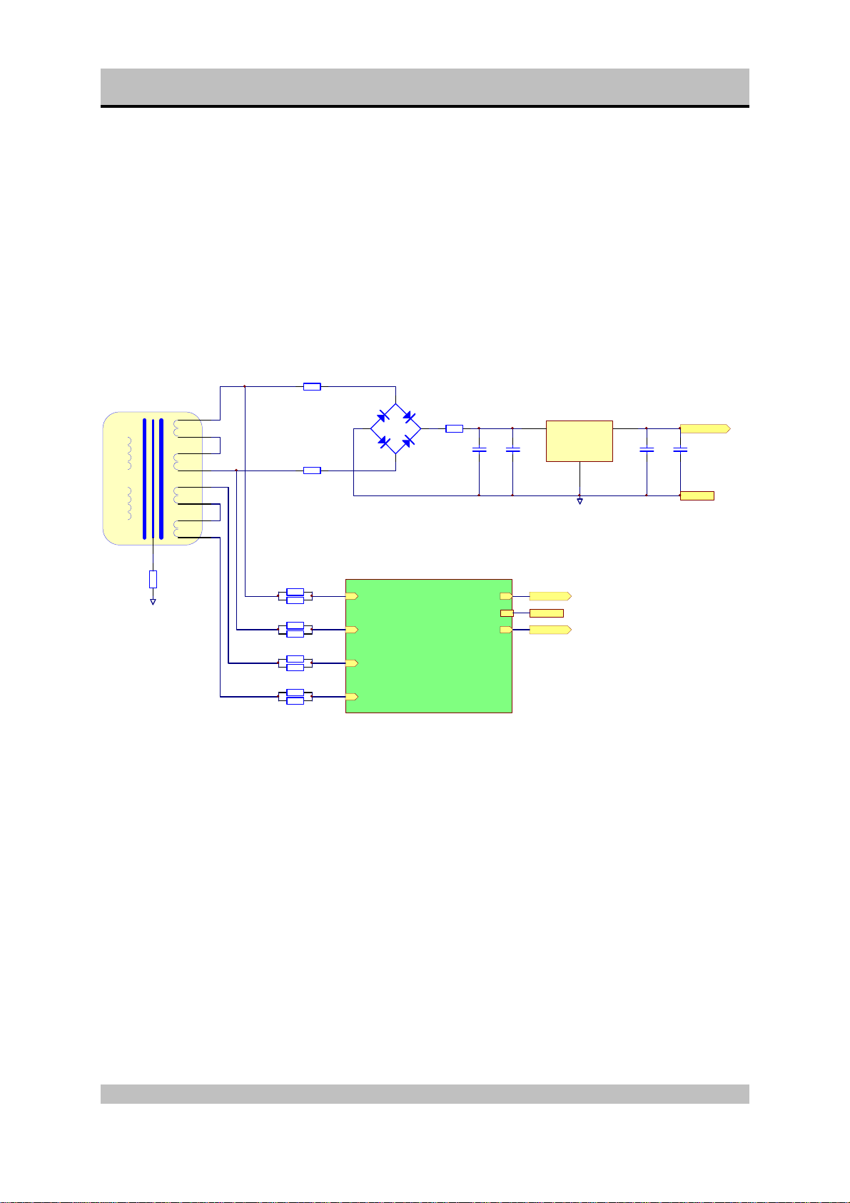
SPHINX Project Two Mk2 Service Manual
Project 2 power supply overview
R3
T1
R-CORE 50VA SEC
120V
120V
14V
14V
14V
14V
R1
R1, R3, R4,R8..R11, R17..R120 : 11 X 10R0
B1
R4
+
C3
330U
50V
100N
C2
U1
L7824C
1
Vin
GND
2
DGND
+24V
3
100N
C1
+D24V
100N
C64
DGND
AGND
R14
10K0
R19
R20
R17
R18
R11
R10
R9
R8
project-2 analog power supply
pj2aps.sch
U1
U1
U2
U2
U3
U3
U4
U4
+22V
+22V
AGND
AGND
-22V
-22V
+22V
AGND
+22V
15
Page 16

SPHINX Project Two Mk2 Service Manual
Project 2 power supply
14VAC
14VAC
U1
U2
U3
U4
220N
C11
D7 D8
220N
D6 D5
C8
220N
C6
D1D4D2
220N
C5
220N
C10
220N
C9
+
C15
+
C12
220N
C7
220N
D3
C4
R21
10R0
R22
10R0
+
+
C16
C17
+
+
C14
C13
R15
10R0
R16
10R0
R12
10R0
R13
10R0
R6
10R0
R7
10R0
+
+
C24
C23
+
+
C21
C20
D1..D8 : 8 X 1N4001
C12..C17
C20..C25 : 16 X 2200U/63V
C40..C43
+
C25
+
C22
T3
A1306
R32
8R6
LD2
LED red
220N
C29
220N
C28
LD1
LED red
R31
8R6
T2
C3298
220N
C37
R50
10K0
R35
10K0
220N
C36
T5
A1306
T4
C3298
R49
10K0
R48
2K00
R37
2K00
T8
A970
R36
10K0
R46
R47
332R
332R
T7
T9
C2240
C2240
R44
1K00
R45
+
150R
C33
330U/50V
+
R40
C32
150R
330U/50V
T6
A970
R41
1K00
R38
R39
332R
332R
R43
10K0
LED red
LD6
LED red
LD5
LED red
LD4
LED red
LD3
R42
10K0
+
C43+C42
+
C40+C41 C44
+22V (+/-1V)
+22V
220N
C45
AGND
AGND
220N
-22V
-22V (+/-1V)
16
Page 17

SPHINX Project Two Mk2 Service Manual
Project 2 input selection
CDTUNERLINE 1LINE 2LINE 3TAPE INTAPE OUTOUT 1OUT 2OUT 3 CD SYM
CN2
132
+D24V
RL1
+
SP3
OGND
R5
-L-OUT +D24V
+L-OUT
-R-OUT
+R-OUT
24R9
CN3
132
OGNDOGND
RL2
+
R23
24R9
O2
R-INPUT
L-INPUT
R144
R145
600R
600R
RL4
RL9
+
O1
O3
AGND
RL6
RL5
+
O4
+
+
O5
CN16ACN16BCN13ACN13BCN1A CN1B CN17A CN17B CN12A
12J212
J5
R70
24R9
R71
24R9
RL8
RL7
+
O6
RL3
+
+
O7
O8
+D24V
O2
DGND
O8
O3
O4
O5
O6
M2
O7
M1
O1
+D24V
R2
4K75
OPT1
OPTOUT
CN19
1
2
3
4
5
6
7
8
9
10
11
12
13
14
15
16
17
18
to display
R60
+22V
+
C48
330U/50V
+
C50
330U/50V
+
C46
330U/50V
+
C38
330U/50V
1R00
R68
-22V
1R00
R52
+22V
1R00
R58
-22V
1R00
AGND
AGND
220N
C49
AGND
AGND
220N
C51
220N
C47
AGND
AGND
220N
C39
AGND
1
R67
3
CN5
2
15K0
AGND
3
R62
5K00
R63
100K
AGND
1
R57
CN4
2
15K0
R54
5K00
R55
100K
AGND
CN20
1
+22V
AGND
4
-22V
CN18
1
AGND
4
C101
33PF
R66
15K0
U5
OPA604AP
R61
5K00
C102
33PF
R56
15K0
U4
OPA604AP
R53
5K00
17
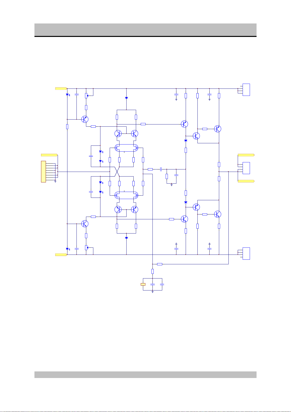
Page 18

SPHINX Project Two Mk2 Service Manual
Project 2 left pre-amp
CN14
L-INPUT
8
7
6
5
4
3
2
1
+22V (+/-1V)
AGND
-22V (+/-1V)
+22V
LED voltage approx. 1.8V
P2
LED red
LD16
R138
33K2
LED red
LD15
-22V
50R
+
R133
C66
243R
T35
A970
R109
± 4mA
2K21
+
C61
+
C60
R102
± 4mA
2K21
T34
C2240
R130
243R
+
C65
P1
50R
LED red
LD10
LED red
LD9
LED red
LD8
LED red
LD7
T31
C2240
T30
A970
R132
200R
R131
200R
R107
2K21
R104
2K21
R128
100R
R126
100R
D12
R106
2K21
R108
51R0
T22
C2240
T26
K389
R122
R119
100R
200R
C58
R100
10R0
47P
R124
R118
100R
200R
T25
J109
T24
A970
R103
51R0
R105
2K21
D9
R76
4K75
R141
600R
12
J3
+
C73
AGND
10N
R93
600R
C70
AGND AGND
D11
R97
18R0
470P
R90
4K75 C56
C74
330U/50V
AGND
R96
18R0
D10
AGND AGND
R92
10N
600R
C69
T17
A1145
T14
C2705
R79
243R
± 7.5mA± 7.5mA
R73
243R
T16
C2705
T15
A1145
R78
51R0
R74
51R0
R80
100R
C53
T11
A1306
R77
10R0
R75
10R0
T10
C3298
R72
100R
C52
CN9
1
4
+L-OUT
CN6
4
1
+L-OUTR
CN8
4
1
18
Page 19
SPHINX Project Two Mk2 Service Manual
Project 2 right pre-amp
+22V (+/-1V) LED voltage approx. 1.8V
+22V
LED red
+
P4
C68
LD18
R139
33K2
R-INPUT +R-OUT
8CN15
7
6
5
4
3
2
1
AGND
8PIN
LED red
LD17
-22V
-22V (+/-1V)
50R
R137
243R
T37
A970
R117
± 4mA
2K21
+
C63
+
C62
R110
± 4mA
2K21
T36
C2240
R134
243R
P3
+
50R
C67
LED red
LD13
LED red
LD14
LED red
LD12
LED red
LD11
T33
C2240
T32
A970
R136
200R
R135
200R
R115
2K21
R112
2K21
R129
100R
R127
100R
D16
R114
2K21
R116
51R0
T23
C2240
T29
K389
R123
R121
100R
200R
C59
R101
10R0
47P
R125
R120
100R
200R
T28
J109
T27
A970
R113
2K21
D13
R85
4K75
R140
600R
12
J4
+
C76
AGND
C75
330U/50V
AGND
R91
4K75 C57
AGND
R111
51R0
AGND
10N
C72
470P
10N
C71
R95
R88
600R
243R
± 7.5mA ± 7.5mA
T21
A1145
T20
C2705
D15
R99
18R0
R98
18R0
D14
T19
A1145
T18
C2705
R82
243R
R94
600R
R87
51R0
R83
51R0
AGND
AGND
R89
100R
C55
T13
A1306
R86
10R0
R84
10R0
T12
C3298
R81
100R
C54
CN11
1
4
4PIN
CN7
4
1
4PIN
+R-OUTR
CN10
4
1
4PIN
19
Page 20
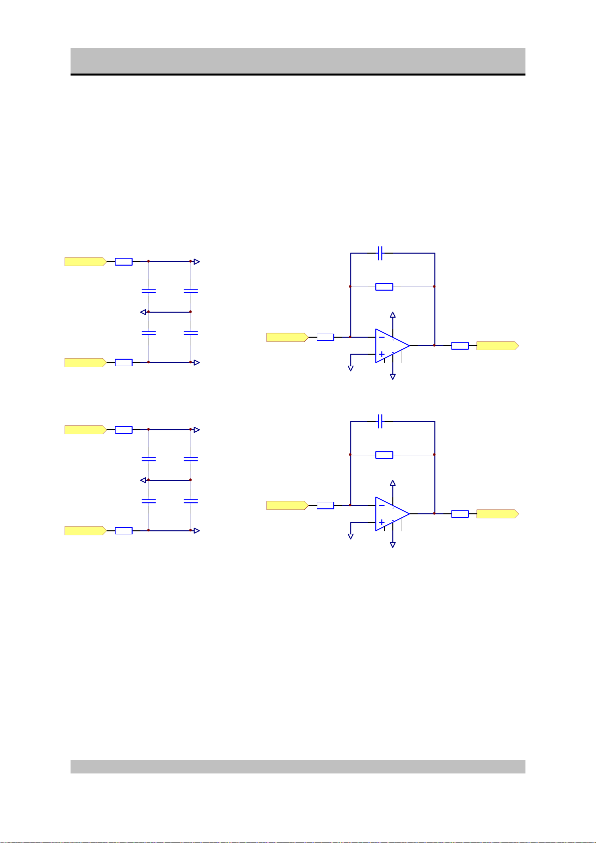
SPHINX Project Two Mk2 Service Manual
CM1
Project 2 phase inverter
+22V
-22V
+22V
-22V
R29
1R00
AGND
R51
1R00
R24
1R00
AGND
R28
1R00
220N
C31
220N
C35
220N
C19
220N
C27
+VR
+
C30
330U/50V
+
C34
330U/50V
-VR
+VL
+
C18
330U/50V
+
C26
330U/50V
-VL
+R-IN
+L-IN
R30
10K0
R25
10K0
OGND
OGND
R33
10K0
R27
10K0
5P6
+VR
-VR
CM2
5P6
+VL
-VL
U3
OPA604AP
U2
OPA604AP
R34
-R-OUT
24R9
R26
-L-OUT
24R9
20
Page 21
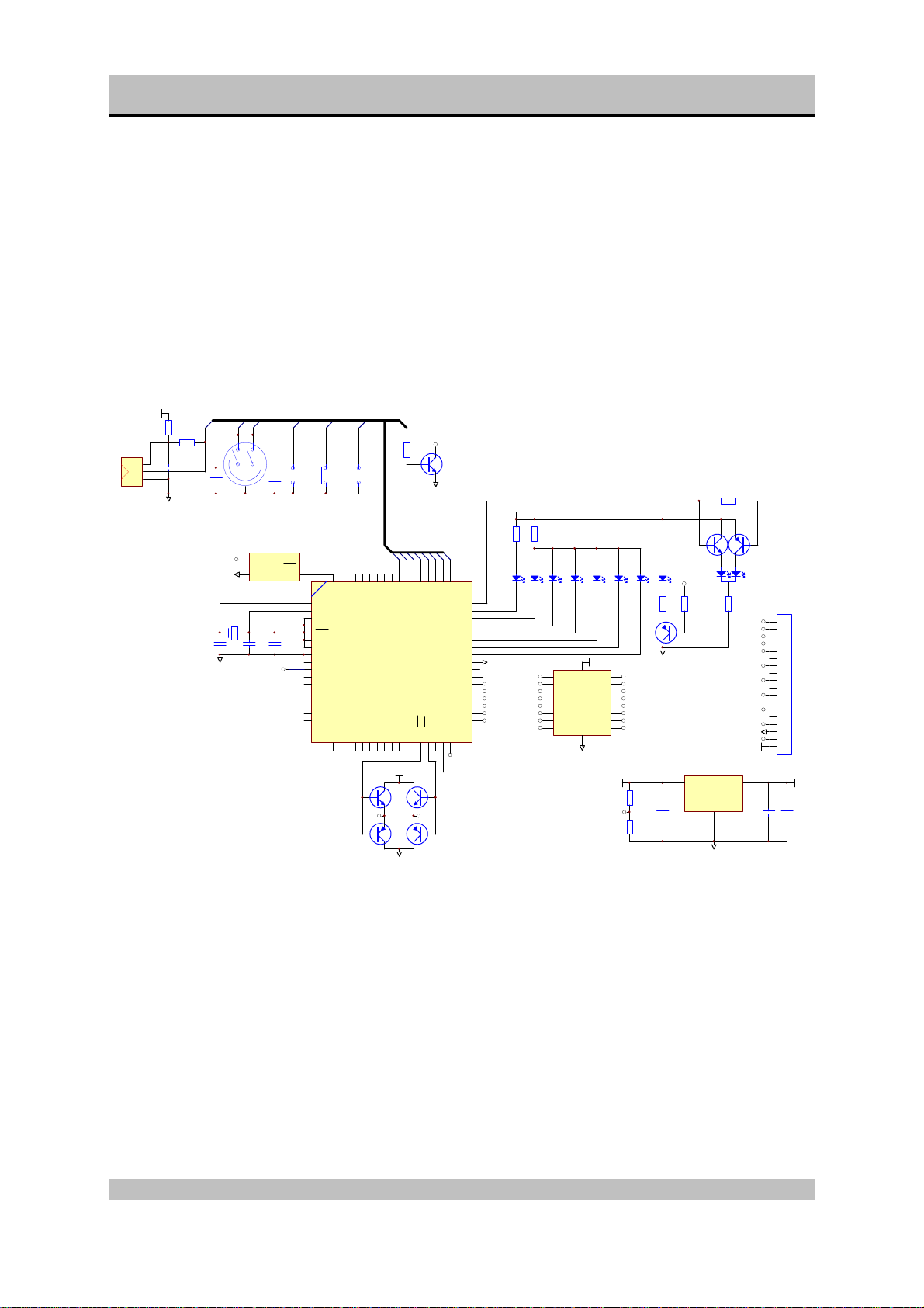
SPHINX Project Two Mk2 Service Manual
C25V/470U
Project 2 display
VCC
R1
5R62
R2
P30
IR1
V+
D
IR
GND
61K9
2
+
C1
C47U/16V
1
3
100NMKT
GND
C9
C5
33p
GND
Input-selector
PFI
GND
U4
8,00000MHz
P32
P33
U5 MAX690
4
PFI
6
WDI
8
VBAT
C7
33p
100NMKT
S1
C8
100NMKT
Standby Tape-mMute
VOUT
PFO
RES
VCC
C6
M
P35
P34
P31
S2
2 1
10
11
12
13
14
15
16
17
18
19
20
21
22
23
24
25
26
1
5
7
U3
Xtal
EXtal
MD1
MD0
NMI
VCC
STBY
GND
nc
P40
P41
P42
P43
P44
P45
P46
P47
S3
2 1
9
P668P657P646P635P624P613P60
RES
S4
2 1
P5027P5128P5229P5330P5431P5532P7033P7134nc35P7236P7337P7438P75/WR39P76/RD40P7741VCC42P27
T7T2SC2240
T6T2SA970
P36
OPTO
R7
10K
T3
T2SC2240
GND
VCC
R8
R10
390R
390R
2nc1
68
P31
P32
P33
P34
P35
P36
P37
H8
VCC
IN1
VCC
T5 T2SC2240
P30
P3061P3162P3263P3364P3465P3566P3667P37
60
P10
59
P11
58
P12
57
P13
56
P14
55
P15
54
P16
53
P17
52
GND
51
nc
50
P20
49
P21
48
P22
47
P23
46
P24
45
P25
44
P26
H8/325 HD6413258CP10
43
GND
IN8
IN7
IN6
IN5
IN4
IN3
IN2
STB
M1M2
T4 T2SA970
CD
TAPE-M
CD-S
LD3 LD4 LD5 LD6 LD7
LD8 LD2
U2
ULN2804
1
IN1
2
IN2
3
IN3
4
IN4
5
IN5
6
IN6
7
IN7
8
IN8
TUNER
LINE1
LINE2
LINE3
MUTE
LD9
R11
390R
10
+24
IN1
OUT1
K
IN2
OUT2
IN3
OUT3
IN4
OUT4
IN5
OUT5
IN6
OUT6
IN7
OUT7
IN8
OUT8
GND
9
GND
GND
18
RL2
17
RL8
16
RL3
15
RL4
14
RL5
13
RL6
12
RL7
11
RL1
+24
PFI
1
R5
39K2
C4
100NMKT
R6
10K
GND
M
T8
T2SA970
U1
MC7805
R9
10K
Vin
T2SC2240
T1
R G
GND
2
GND
R4
10K
T2
T2SA970
STANDBY
LD1
R3
RL1
M1
RL7
M2
RL6
RL5
RL4
RL3
RL8
OPTO
GND
RL2
+24
3
100NMKT
CN1
18
17
16
15
14
13
12
11
10
9
8
7
6
5
4
3
2
1
18PIN
VCC
C3
+
C2
390R
+5V
PCB 02601B-AS-SISW
1
21
Page 22

SPHINX Project Two Mk2 Service Manual
PCB drawings of Project 2 Mk2
Because there is a significant image-quality loss during the conversion of the drawings, the PCB-drawings are
located in seperate files.
These files are in PDF-format (Adobé Acrobat 3.0 Reader).
• Pj2Main.PDF for Mainboard
• Pj2Display.PDF for Displayboard
• Pj2Adjust.PDF for adjustment procedures
22
Page 23

SPHINX Project Two Mk2 Service Manual
Partlist pre-amp
Designator Part Type Description
B1 W02M Bridge rectifier
C1 100nF MKT capacitor
C10 220nF MKT capacitor
C101 33pF Ceramic capacitor
C102 33pF Ceramic capacitor
C11 220nF MKT capacitor
C12 2200uF/63V Electrolytic capacitor
C13 2200uF/63V Electrolytic capacitor
C14 2200uF/63V Electrolytic capacitor
C15 2200uF/63V Electrolytic capacitor
C16 2200uF/63V Electrolytic capacitor
C17 2200uF/63V Electrolytic capacitor
C18 330uF/50V Electrolytic capacitor
C19 220nF MKT capacitor
C2 100nF MKT capacitor
C20 2200uF/63V Electrolytic capacitor
C21 2200uF/63V Electrolytic capacitor
C22 2200uF/63V Electrolytic capacitor
C23 2200uF/63V Electrolytic capacitor
C24 2200uF/63V Electrolytic capacitor
C25 2200uF/63V Electrolytic capacitor
C26 330uF/50V Electrolytic capacitor
C27 220nF MKT capacitor
C28 220nF MKT capacitor
C29 220nF MKT capacitor
C3 330uF/50V Electrolytic capacitor
C30 330uF/50V Electrolytic capacitor
C31 220nF MKT capacitor
C32 330uF/50V Electrolytic capacitor
C33 330uF/50V Electrolytic capacitor
C34 330uF/50V Electrolytic capacitor
C35 220nF MKT capacitor
C36 220nF MKT capacitor
C37 220nF MKT capacitor
C38 330uF/50V Electrolytic capacitor
C39 220nF MKT capacitor
C4 220nF MKT capacitor
C40 2200uF/63V Electrolytic capacitor
C41 2200uF/63V Electrolytic capacitor
C42 2200uF/63V Electrolytic capacitor
C43 2200uF/63V Electrolytic capacitor
C44 220nF MKT capacitor
C45 220nF MKT capacitor
C46 330uF/50V Electrolytic capacitor
C47 220nF MKT capacitor
C48 330uF/50V Electrolytic capacitor
C49 220nF MKT capacitor
23
Page 24

SPHINX Project Two Mk2 Service Manual
Designator Part Type Description
C5 220nF MKT capacitor
C50 330uF/50V Electrolytic capacitor
C51 220nF MKT capacitor
C52 220nF MKT capacitor
C53 220nF MKT capacitor
C54 220nF MKT capacitor
C55 220nF MKT capacitor
C56 470pF Styroflex capacitor
C57 470pF Styroflex capacitor
C58 47pF Styroflex capacitor
C59 47pF Styroflex capacitor
C6 220nF MKT capacitor
C60 47uF/25V Electrolytic capacitor
C61 47uF/25V Electrolytic capacitor
C62 47uF/25V Electrolytic capacitor
C63 47uF/25V Electrolytic capacitor
C64 100nF MKT capacitor
C65 47uF/25V Electrolytic capacitor
C66 47uF/25V Electrolytic capacitor
C67 47uF/25V Electrolytic capacitor
C68 47uF/25V Electrolytic capacitor
C69 10nF MKT capacitor
C7 220nF MKT capacitor
C70 10nF MKT capacitor
C71 10nF MKT capacitor
C72 10nF MKT capacitor
C73 220nF MKT capacitor
C74 330uF/50V Electrolytic capacitor
C75 330uF/50V Electrolytic capacitor
C76 220nF MKT capacitor
C77 220pF Styroflex capacitor
C78 220pF Styroflex capacitor
C8 220nF MKT capacitor
C9 220nF MKT capacitor
CM1 56pF Ceramic capacitor
CM2 56pF Ceramic capacitor
CN1 CINCH4P Cinch plug
CN10 4PIN 4 pins header
CN11 4PIN 4 pins header
CN12 CINCH2P Cinch plug
CN13 CINCH4P Cinch plug
CN14 8PIN 8 pins header
CN15 8PIN 8 pins header
CN16 CINCH4P Cinch plug
CN17 CINCH4P Cinch plug
CN18 4PIN 4 pins header
CN19 18PIN 4 pins header
CN2 XLR-M XLR connector male
CN20 4PIN 4 pins header
24
Page 25

SPHINX Project Two Mk2 Service Manual
Designator Part Type Description
CN21 PHONEJACK Phone jack
CN22 KAST_GND Ground connection with case
CN3 XLR-Male XLR connector male
CN4 XLR-Female XLR connector female
CN5 XLR-Female+B51 XLR connector female
CN6 4PIN 4 pins header
CN7 4PIN 4 pins header
CN8 4PIN 4 pins header
CN9 4PIN 4 pins header
D1 1N4001 Diode
D10 1N4148 Diode
D11 1N4148 Diode
D12 1N4148 Diode
D13 1N4148 Diode
D14 1N4148 Diode
D15 1N4148 Diode
D16 1N4148 Diode
D2 1N4001 Diode
D3 1N4001 Diode
D4 1N4001 Diode
D5 1N4001 Diode
D6 1N4001 Diode
D7 1N4001 Diode
D8 1N4001 Diode
D9 1N4148 Diode
J2 Jumper Jumper
J5 Jumper Jumper
LD1 LED red LED red
LD10 LED red LED red
LD11 LED red LED red
LD12 LED red LED red
LD13 LED red LED red
LD14 LED red LED red
LD15 LED red LED red
LD16 LED red LED red
LD17 LED red LED red
LD18 LED red LED red
LD2 LED red LED red
LD3 LED red LED red
LD4 LED red LED red
LD5 LED red LED red
LD6 LED red LED red
LD7 LED red LED red
LD8 LED red LED red
LD9 LED red LED red
OPT1 173298-2 Optical output
25
Page 26

SPHINX Project Two Mk2 Service Manual
Designator Part Type Description
P1 50R Adjustable pot.
P2 50R Adjustable pot.
P3 50R Adjustable pot.
P4 50R Adjustable pot.
P5 ALPS POT M Stereo motor pot.
R1 10R0 Resistor MRS25
R10 10R0 Resistor MRS25
R100 10R0 Resistor MRS25
R101 10R0 Resistor MRS25
R102 2K21 Resistor MRS25
R103 51R0 Resistor MRS25
R104 2K21 Resistor MRS25
R105 2K21 Resistor MRS25
R106 2K21 Resistor MRS25
R107 2K21 Resistor MRS25
R108 51R0 Resistor MRS25
R109 2K21 Resistor MRS25
R11 10R0 Resistor MRS25
R110 2K21 Resistor MRS25
R111 51R0 Resistor MRS25
R112 2K21 Resistor MRS25
R113 2K21 Resistor MRS25
R114 2K21 Resistor MRS25
R115 2K21 Resistor MRS25
R116 51R0 Resistor MRS25
R117 2K21 Resistor MRS25
R118 200R Resistor MRS25
R119 200R Resistor MRS25
R12 10R0 Resistor MRS25
R120 200R Resistor MRS25
R121 200R Resistor MRS25
R122 100R Resistor MRS25
R123 100R Resistor MRS25
R124 100R Resistor MRS25
R125 100R Resistor MRS25
R126 100R Resistor MRS25
R127 100R Resistor MRS25
R128 100R Resistor MRS25
R129 100R Resistor MRS25
R13 10R0 Resistor MRS25
R130 243R Resistor MRS25
R131 200R Resistor MRS25
R132 200R Resistor MRS25
R133 243R Resistor MRS25
R134 243R Resistor MRS25
R135 200R Resistor MRS25
R136 200R Resistor MRS25
R137 243R Resistor MRS25
R138 33K2 Resistor MRS25
26
Page 27

SPHINX Project Two Mk2 Service Manual
Designator Part Type Description
R139 33K2 Resistor MRS25
R14 10K0 Resistor MRS25
R140 600R Resistor MRS25
R141 600R Resistor MRS25
R142 1K00 Resistor MRS25
R143 1K00 Resistor MRS25
R144 600R Resistor MRS25
R145 600R Resistor MRS25
R15 10R0 Resistor MRS25
R16 10R0 Resistor MRS25
R17 10R0 Resistor MRS25
R18 10R0 Resistor MRS25
R19 10R0 Resistor MRS25
R2 4K75 Resistor MRS25
R20 10R0 Resistor MRS25
R21 10R0 Resistor MRS25
R22 10R0 Resistor MRS25
R23 24R9 Resistor MRS25
R24 1R00 Resistor MRS25
R25 10K0 Resistor MRS25
R26 24R9 Resistor MRS25
R27 10K0 Resistor MRS25
R28 1R00 Resistor MRS25
R29 1R00 Resistor MRS25
R3 10R0 Resistor MRS25
R30 10K0 Resistor MRS25
R31 8R6 Resistor MRS25
R32 8R6 Resistor MRS25
R33 10K0 Resistor MRS25
R34 24R9 Resistor MRS25
R35 10K0 Resistor MRS25
R36 10K0 Resistor MRS25
R37 2K00 Resistor MRS25
R38 332R Resistor MRS25
R39 332R Resistor MRS25
R4 10R0 Resistor MRS25
R40 150R Resistor MRS25
R41 1K00 Resistor MRS25
R42 10K0 Resistor MRS25
R43 10K0 Resistor MRS25
R44 1K00 Resistor MRS25
R45 150R Resistor MRS25
R46 332R Resistor MRS25
R47 332R Resistor MRS25
R48 2K00 Resistor MRS25
R49 10K0 Resistor MRS25
R5 24R9 Resistor MRS25
R50 10K0 Resistor MRS25
R51 1R00 Resistor MRS25
R52 1R00 Resistor MRS25
27
Page 28

SPHINX Project Two Mk2 Service Manual
Designator Part Type Description
R53 5K00 Resistor MRS25
R54 5K00 Resistor MRS25
R55 100K Resistor MRS25
R56 15K0 Resistor MRS25
R57 15K0 Resistor MRS25
R58 1R00 Resistor MRS25
R6 10R0 Resistor MRS25
R60 1R00 Resistor MRS25
R61 5K00 Resistor MRS25
R62 5K00 Resistor MRS25
R63 100K Resistor MRS25
R64 600R Resistor MRS25
R65 600R Resistor MRS25
R66 15K0 Resistor MRS25
R67 15K0 Resistor MRS25
R68 1R00 Resistor MRS25
R7 10R0 Resistor MRS25
R70 24R9 Resistor MRS25
R71 24R9 Resistor MRS25
R72 100R Resistor MRS25
R73 243R Resistor MRS25
R74 51R0 Resistor MRS25
R75 10R0 Resistor MRS25
R76 4K75 Resistor MRS25
R77 10R0 Resistor MRS25
R78 51R0 Resistor MRS25
R79 243R Resistor MRS25
R8 10R0 Resistor MRS25
R80 100R Resistor MRS25
R81 100R Resistor MRS25
R82 243R Resistor MRS25
R83 51R0 Resistor MRS25
R84 10R0 Resistor MRS25
R85 4K75 Resistor MRS25
R86 10R0 Resistor MRS25
R87 51R0 Resistor MRS25
R88 243R Resistor MRS25
R89 100R Resistor MRS25
R9 10R0 Resistor MRS25
R90 4K75 Resistor MRS25
R91 4K75 Resistor MRS25
R92 600R Resistor MRS25
R93 600R Resistor MRS25
R94 600R Resistor MRS25
R95 600R Resistor MRS25
R96 18R0 Resistor MRS25
R97 18R0 Resistor MRS25
R98 18R0 Resistor MRS25
R99 18R0 Resistor MRS25
28
Page 29

SPHINX Project Two Mk2 Service Manual
Designator Part Type Description
RL1 Alcatel 24V MT2 DIL relay
RL2 Alcatel 24V MT2 DIL relay
RL3 Alcatel 24V MT2 DIL relay
RL4 Alcatel 24V MT2 DIL relay
RL5 Alcatel 24V MT2 DIL relay
RL6 Alcatel 24V MT2 DIL relay
RL7 Alcatel 24V MT2 DIL relay
RL8 Alcatel 24V MT2 DIL relay
RL9 Alcatel 24V MT2 DIL relay
SP1 SILPAD Soldering pad
SP2 SILPAD Soldering pad
SP3 SILPAD Soldering pad
SP4 SILPAD Soldering pad
SP5 SILPAD Soldering pad
SP6 SILPAD Soldering pad
T1 R-CORE 50VA SEC Transformer
T10 2SC3298 Transistor
T11 2SA1306 Transistor
T12 2SC3298 Transistor
T13 2SA1306 Transistor
T14 2SC2240 Transistor
T15 2SA1145 Transistor
T16 2SC2705 Transistor
T17 2SA1145 Transistor
T18 2SC2240 Transistor
T19 2SA1145 Transistor
T2 2SC3298 Transistor
T20 2SC2705 Transistor
T21 2SA1145 Transistor
T22 2SC2240 Transistor
T23 2SC2240 Transistor
T24 2SA970 Transistor
T25 2SJ109 Dual P-JFET
T26 2SK389 Dual N-JFET
T27 2SA970 Transistor
T28 2SJ109 Dual P-JFET
T29 2SK389 Dual N-JFET
T3 2SA1306 Transistor
T30 2SA970 Transistor
T31 2SC2240 Transistor
T32 2SA970 Transistor
T33 2SC2240 Transistor
T34 2SC2240 Transistor
T35 2SA970 Transistor
T36 2SC2240 Transistor
T37 2SA970 Transistor
T4 2SC3298 Transistor
29
Page 30

SPHINX Project Two Mk2 Service Manual
Designator Part Type Description
T5 2SA1306 Transistor
T6 2SA970 Transistor
T7 2SC2240 Transistor
T8 2SA970 Transistor
T9 2SC2240 Transistor
U1 L7824C Voltage regulator
U2 OPA604AP IC
U3 OPA604AP IC
U4 OPA604AP IC
U5 OPA604AP IC
30
Page 31

SPHINX Project Two Mk2 Service Manual
Partlist display
Designator Part Type Description
C1 47uF/16V Electrolytic capacitor
C2 470uF/25V Electrolytic capacitor
C3 100nF MKT capacitor
C4 100nF MKT capacitor
C5 33pF Ceramic capacitor
C6 100nF MKT capacitor
C7 33pF Ceramic capacitor
C8 100nF MKT capacitor
C9 100nF MKT capacitor
CN1 18PIN 18 pins header
IR1 SHARP GP1U5 Infrared receiver
LD1 LD2C LED
LD2 TLL46221C LED red
LD3 TLL46221C LED red
LD4 TLL46221C LED red
LD5 TLL46221C LED red
LD6 TLL46221C LED red
LD7 TLL46221C LED red
LD8 TLL46221C LED red
LD9 TLL46221C LED red
R1 5R62 Resistor MRS25
R10 390R Resistor MRS25
R11 390R Resistor MRS25
R2 61K9 Resistor MRS25
R3 390R Resistor MRS25
R4 10K Resistor MRS25
R5 39K2 Resistor MRS25
R6 10K Resistor MRS25
R7 10K Resistor MRS25
R8 390R Resistor MRS25
R9 10K Resistor MRS25
S1 ENCOJ-B24-AE0006 Switch
S2 ITW 60 1000 Switch
S3 ITW 60 1000 Switch
S4 ITW 60 1000 Switch
T1 2SC2240 Transistor
T2 2SA970 Transistor
T3 2SC2240 Transistor
T4 2SA970 Transistor
T5 2SC2240 Transistor
T6 2SA970 Transistor
T7 2SC2240 Transistor
31
Page 32

SPHINX Project Two Mk2 Service Manual
Designator Part Type Description
T8 2SA970 Transistor
U1 MC7805 IC
U2 ULN2804 IC
U3 H8/325 HD6413258CP10 IC
U4 8,00000MHz X-TAL
U5 MAX690 IC
©1998 Audioscript BV
Version: 2-09-98
32
 Loading...