

Page 1
1.
SERVICE MANUAL
PROJECT TEN
INTEGRATED
STEREO AMPLIFIER
Page 2

SPHINX Project Ten Service Manual
2
1. UNPACKING.......................................................................................................................................3
2. SPHINX WARRANTY CARD..............................................................................................................3
3. CONTACTING THE MANUFACTURER.............................................................................................3
4. THE AMP AT A GLANCE...................................................................................................................4
Front panel................................................................................................................................................... 4
Rear panel ...................................................................................................................................................5
5. SPHINX REMOTE CONTROL............................................................................................................6
Buttons and LED indication..........................................................................................................................6
Operation.....................................................................................................................................................7
Selecting without switching..........................................................................................................................7
Batteries.......................................................................................................................................................7
Encountering problems................................................................................................................................7
6. TECHNICAL SPECIFICATIONS.........................................................................................................8
7. GENERAL CHECKLIST .....................................................................................................................9
Protection modes.........................................................................................................................................9
Short Circuit.............................................................................................................................................9
Standby mode.............................................................................................................................................. 9
Necessary Equipment..................................................................................................................................9
8. ADJUSTMENT PROCEDURES........................................................................................................10
Bias............................................................................................................................................................10
Offset ......................................................................................................................................................... 11
9. PROBLEMS AND SOLUTIONS .......................................................................................................12
10. DIAGRAMS AND PARTS LISTS ....................................................................................................13
Connection diagram bias adjustment.........................................................................................................14
Connection diagram offset adjustment.......................................................................................................15
Connections main board and display board of Project 10..........................................................................16
General overview Project 10......................................................................................................................17
Project 10 power supply and input selection..............................................................................................18
Project 10 volume board............................................................................................................................19
Project 10 amplifier left ..............................................................................................................................20
Project 10 amplifier right ............................................................................................................................ 21
Project 10 control.......................................................................................................................................22
PCB drawings of Project 10.......................................................................................................................23
Parts list.....................................................................................................................................................24
Page 3

SPHINX Project Ten Service Manual
3
The Sphinx Project Ten design
The Sphinx Project Ten was designed for the everincreasing group of quality-conscious audiophiles.
We are very proud of the tradition connected with
the SPHINX name, especially concerning audio
quality perfection.
This service manual will help you to optimally
service and repair the Sphinx Project Ten
Integrated Stereo Amplifier
This integrated high-end stereo amplifier is of
exceptional quality. With exception of the balanced
input section, it is of discrete design throughout (no
IC's are used). The pre-amp section is built around
Dual FET's and the amplifier is DC-coupled from
input to output.
The two mono power amps (each channel is totally
independent) use special power transistors with a
power bandwidth of over 20 MHz, a very fast slew
rate and an unsurpassed phase linearity over the
power bandwidth. The amplifiers are therefore very
stable and can effortlessly drive every type and
format of loudspeaker (even the most complex ones
such as electrostatic and magnetostatic...) at
maximum quality.
All internal audio cabling is Siltech pure silver and
the amp outputs are sent to the loudspeaker
connectors via heavy duty, completely sealed goldplated relays.
To obtain the maximum quality from this integrated
amp it is necessary for it to be properly aligned and
to be used with top quality audio components,
preferably other Sphinx components.
1. UNPACKING
Before leaving the factory every Project Ten is
subjected to stringent and extensive technical and
exterior quality inspection. This ensures the user
many years of high quality audio from a perfectlooking product.
We recommend owners to ship the Project Ten in
its original carton.
After unpacking the Project Ten we therefore
recommend you carefully check it for any transport
damage.
If you find any damage and the product has not
been shipped in the original carton the ensuring
repair costs will not be covered by the warranty.
2. SPHINX WARRANTY CARD
To be entitled to any warranty repairs the owner
must have send the filled out warranty card to
Sphinx or a distributor where it has been registered.
Other regulations may apply in your specific
country: when in doubt, please consult the proper
authorities.
3. CONTACTING THE MANUFACTURER
In case of any problem not covered in this manual
or if you have other questions you may contact the
Sphinx International Service Department in The
Netherlands (local time: GMT +1h) during office
hours at the following numbers:
Telephone (+31) 35 602 0302
Fax (+31) 35 602 2806
E-mail audionl@euronet.nl
It is always very helpful and efficient if you have all
relevant information about the specific product and
the problem ready.
Please also refer to the User Manual of the
Project Ten for information about functions
not described in this manual.
It is important to familiarise yourself with the
special functions, operation and possibilities
of the Sphinx Project Ten.
Page 4
SPHINX Project Ten Service Manual
4
4. THE AMP AT A GLANCE
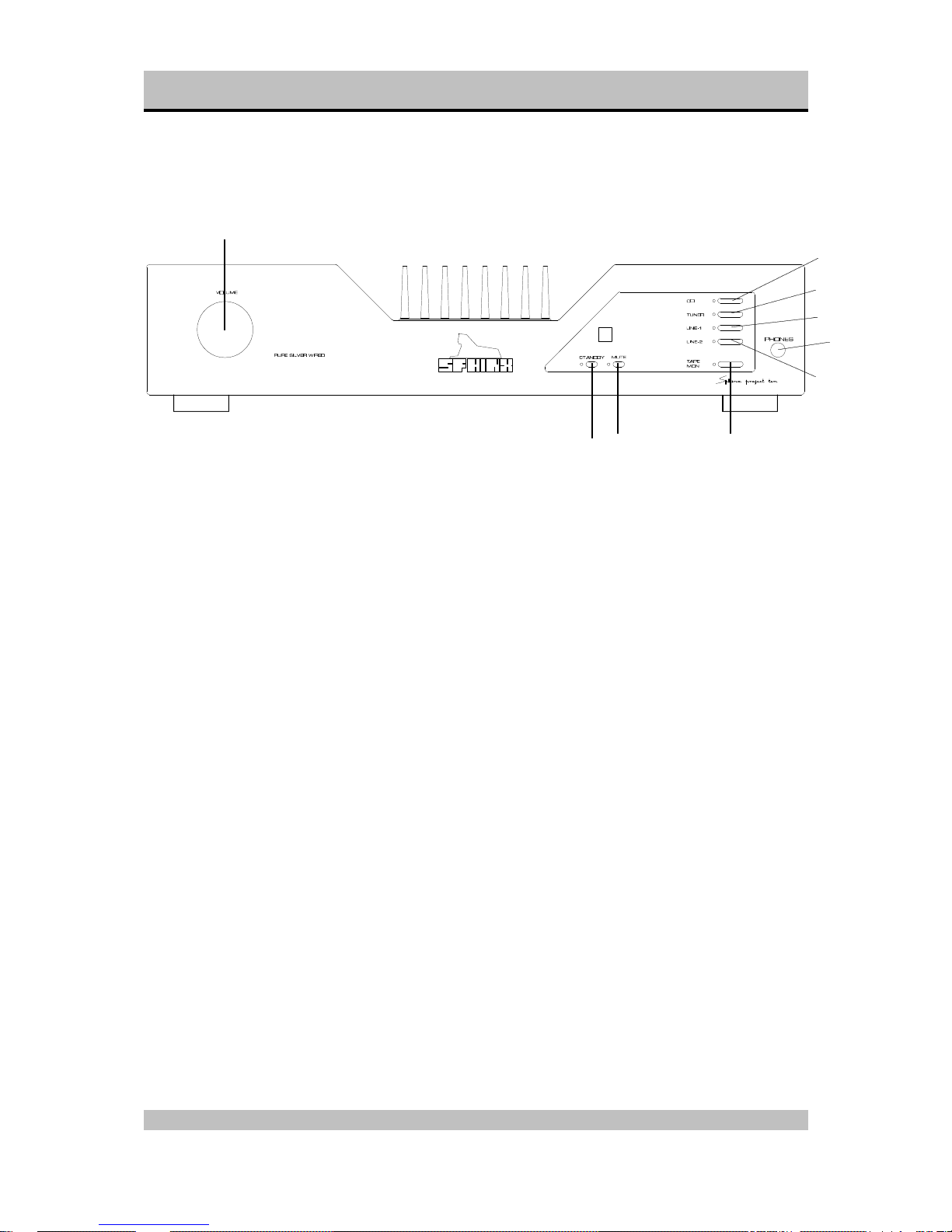
Front panel
1. VOLUME: With this motor-controlled knob you
may adjust the volume of the loudspeakers.
The volume can be controlled manually or via the
optional Remote Control.
2. STANDBY: To switch the component on and off.
When the component is 'off' (standby) this is
indicated by the red LED.
When the component is active the LED will be
green.
3. MUTE: Press this button to temporarily mute the
sound. The red LED will light.
4. CD: To select the CD input.
5. TUNER: To select the TUNER input.
6. LINE 1: To select the LINE 1 input.
7. LINE 2: To select the LINE 2 input (cinch or
balanced).
8. TAPE MON: To select the TAPE IN input.
As soon as you have pressed one of the buttons
5. to 9. the corresponding red LED next to it will
light.
9. PHONES: To connect dynamic stereo
headphones.
1
2
3
4
5
6
9
7
8
Page 5
SPHINX Project Ten Service Manual
5
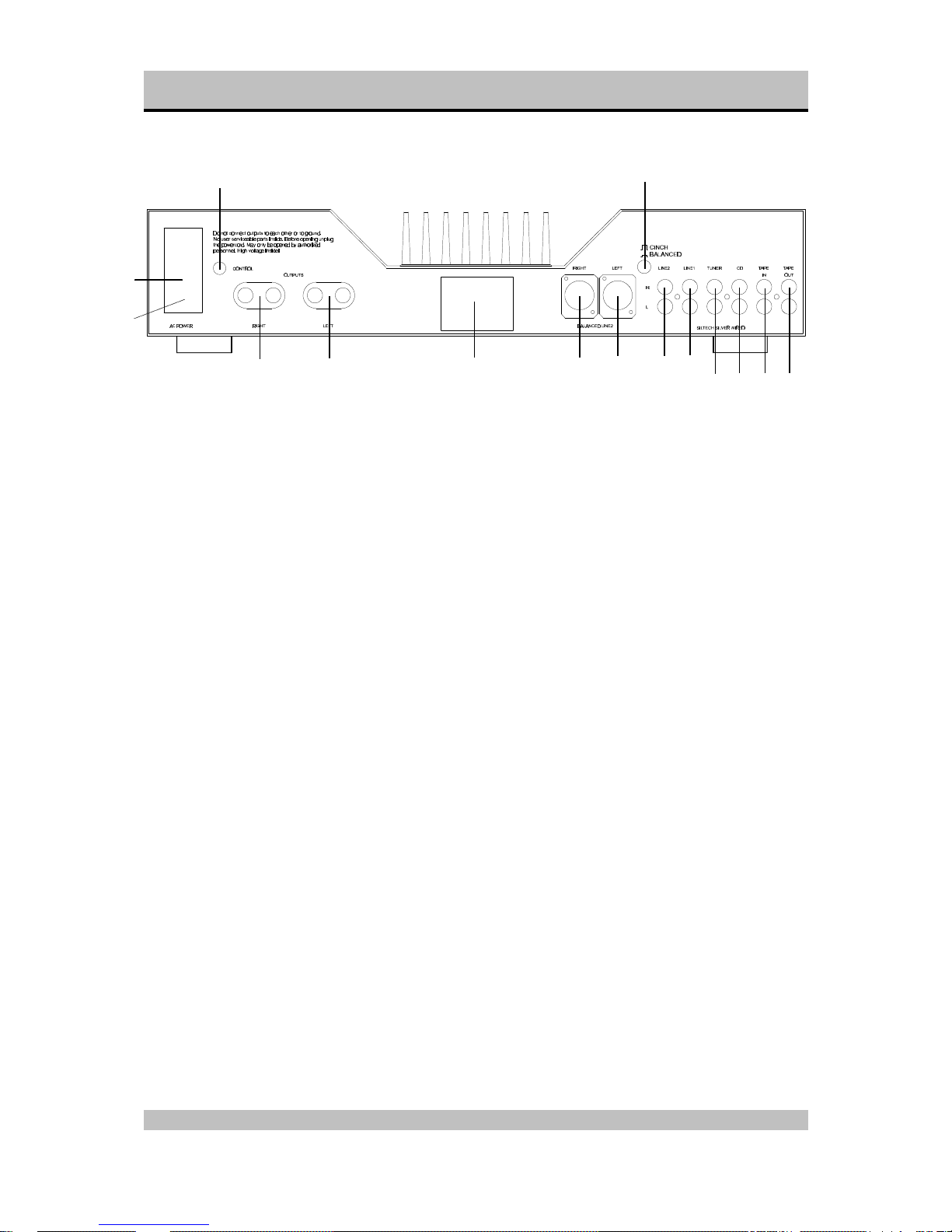
Rear panel
11. ON/OFF: This is the mains power switch.
12. Fuse holder: Contains a fuse (3.15 A slow).
13. AC Power: Connect the mains cable to a mains
power outlet (230 - 240 VAC).
14. CONTROL OUT: To connect the optical cable
going to another Sphinx component.
15. RIGHT OUTPUT: To connect the cable from the
right loudspeaker:
red +
white -
16. LEFT OUTPUT: To connect the cable from the
left loudspeaker:
red +
white -
17. Manufacturer's label: This shows important
data for the component, such as serial number
and mains power voltage.
18. BALANCED LINE 2 RIGHT: To connect the
XLR signal cable (balanced cable) from the right
output of the signal source for Input 2.
19. BALANCED LINE 2 LEFT: To connect the XLR
signal cable (balanced cable) from the left
output of the signal source for Input 2.
20. CINCH/BALANCED: This switch is to select the
input connector for LINE 2:
out LINE 2 (cinch)
in BALANCED LINE 2
21. LINE 2: To connect the cinch signal cable from
the signal source for LINE 2.
22. LINE 1: To connect the cinch signal cable from
the signal source for LINE 1.
23. TUNER: To connect the cinch signal cable from
the tuner.
24. CD: To connect the cinch signal cable from the
CD player.
25. TAPE IN: Connect this input to the output of the
recorder.
26. TAPE OUT: Connect this output to the Input of
the recorder..
11
12
13
14
15
16
17 18
19
20
21
22
23
24 25 26
Page 6
SPHINX Project Ten Service Manual
6
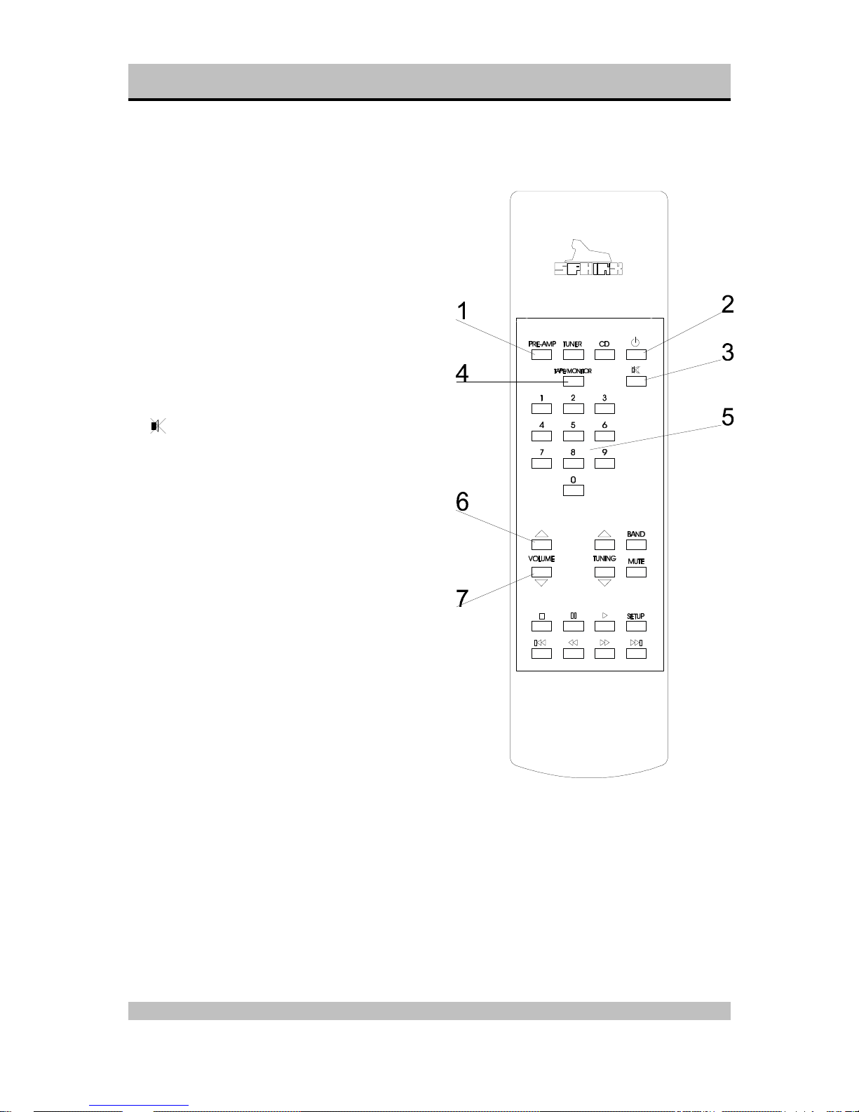
5. SPHINX REMOTE CONTROL
This single Sphinx Remote Control lets you control
all functions: not only of the Project Ten, but of all
other Sphinx equipment.
Only the following buttons and indications on the
Remote apply to the Project Ten (the others will not
function):
Buttons and LED indication
1. PRE-AMP: To select the amp. All buttons
pressed hereafter will only control the amp
functions.
The buttons TUNER and CD will have no effect
on the amp.
2. STANDBY: Use this red button to switch the
Project Ten to stand-by.
3. : Pressing this green button mutes the
outputs (temporarily) and you will not hear any
sound. The red LED will be illuminated. Another
press on this button un-mutes the outputs
4. TAPE/MONITOR: Use this button to select the
Tape IN input. Pressing this button has the
same effect as pressing the TAPE button on the
front panel.
Note: The LED of the selected input (see 5.) will
remain illuminated.
5. 1 - 4: To select inputs CD to Line 2 .
1 CD
2 Tuner
3 Line1
4 Line 2
6. ñ button: Pressing this button has the same
effect as clockwise rotating the VOLUME control
on the front panel. You will increase the volume.
7. ò button: Pressing this button has the same
effect as anti-clockwise rotating the VOLUME
control on the front panel. You will decrease the
volume.
Page 7
SPHINX Project Ten Service Manual
7
Operation
The Sphinx Remote is used for several different
models and can therefore transmit different control
codes, depending on which model has been
selected with the select buttons (1.).
Important: Always press the PRE-AMP button
before you send a command (even if you only have
one Sphinx component).
If not it is possible that although the Remote will
send a signal (LED blinks) nothing happens
because the transmitted signal is not 'recognised' by
the component.
Indoors the Remote may be used up to a distance
of 7 meter, provided there is no strong sunlight in
the room and if you aim the Remote at the
component.
Always aim the Remote straight at the front panel of
the component, the maximum offset angle is 30°.
Selecting without switching
Suppose for instance that you would like to select
the Tuner to Radio 4 without interrupting the CD
playback.
In that case you momentarily depress (not longer
than 0.5 sec) the 'TUNER' button and the '4' button.
The same procedure is used for the other system
components
How to operate the Remote Control with the
different Sphinx components will be explained in the
corresponding User Manual of each component.
Batteries
The four batteries have a life span of approx. one
year during normal use, but shorter when used
more intensely.
Replacement batteries: 1.5 V, model penlight or
AAA . You may also use rechargeable 1.5 V
batteries.
Note: Position the new batteries exactly as shown in
the illustration at the bottom of the battery
compartment, otherwise the Remote will not
function!
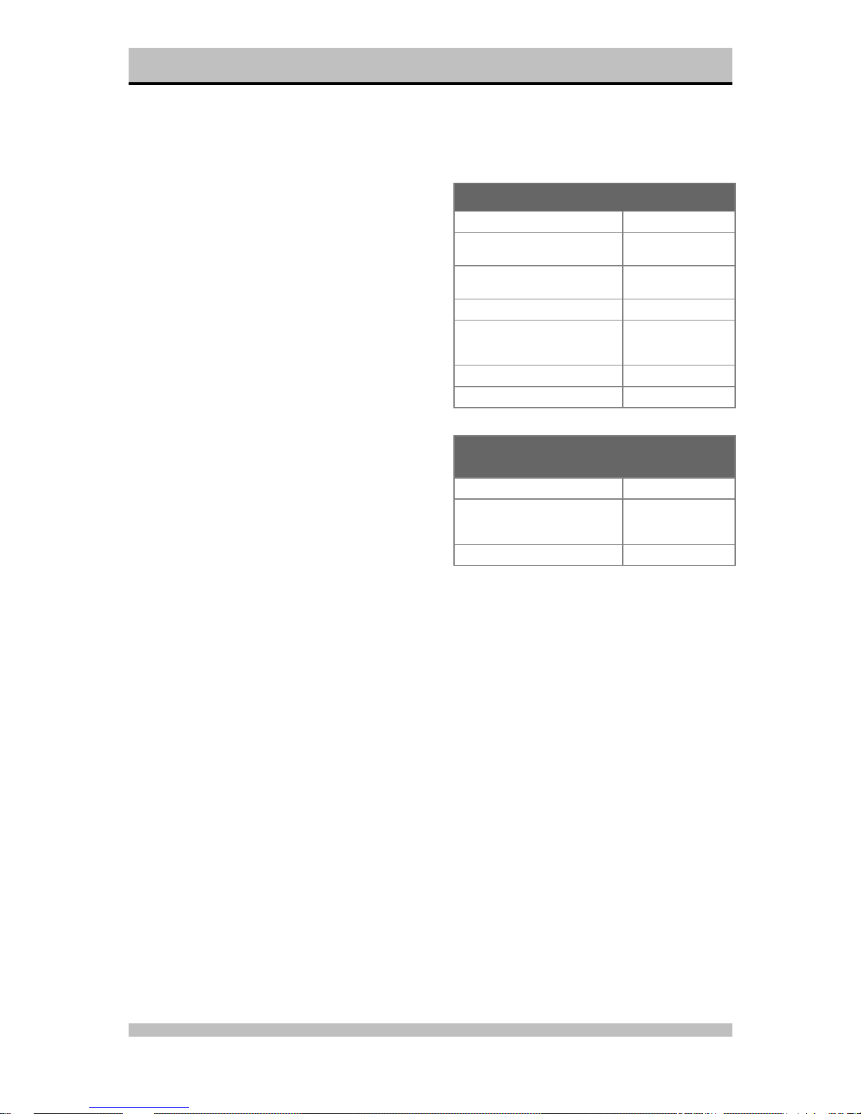
Encountering problems...
Remote Control does not work
Wrong component selected Select the correct one
Distance to component exceeds 7mUse remote at closer
range
Angle between Remote and
component exceeds ±30°
Decrease angle
Sensor window on front dirty Clean window
Batteries empty or incorrectly
placed
Use new batteries or
replace the old ones
correctly
Strong (sun)light in room Shade off
Component is not switched on (!) Switch it on
Component reacts differently than expected or
not at all
Wrong component selected Select the correct one
Component or remote does not
function
Check component
with it's original
remote
Batteries of remote empty Use new batteries
Page 8

SPHINX Project Ten Service Manual
8
6. TECHNICAL SPECIFICATIONS
Bandwidth 0 - 60,000 Hz (+0/-3 dB with RF input filter)
Phase response error <15° (from 0 - 20,000 Hz)
Gain 21 dB max.
Minimum Power Output (1 - 20.000 Hz)
>2x 80 W into 8 Ω (19.0 dBW), THD <0.01%
>2x 120 W into 4 Ω (20.8 dBW), THD <0.02%
>2x 160 W into 2 Ω (22.0 dBW), THD <0.02%
Output voltage / current, max. 34 V / 20 A
THD+N (IHF-A)
<0.01% (80 W into 8 Ω)
IMD <0.03%
S/N ratio (IHF-A) >106 dB
Channel separation >80 dB (1 - 20,000 Hz)
Slew rate >25 V/µs
Damping factor >200 (1 - 20,000 Hz)
Inputs
XLR, balanced
cinch, unbalanced
1x Line 2
1x Line 2, 1x Line 1, 1x CD, 1x Tuner, 1x Tape
level, nominal
0.15 V (-16.5 dBV) for 60 W into 8 Ω
impedance
20 kΩ (3 kΩ balanced)
Outputs
cinch 1x Tape
level 10 V max. (20 dBV) (1 - 20,000 Hz, THD <0.01%)
headphones 1x 6.3 mm stereo jack, adjustable level
clamp 1x loudspeaker L, 1x loudspeaker R
Supply capacitance 54,400 µF per channel
Power consumption 480 W max. (57.5 W standby)
Dimensions (h x w x d) 110 x 482 x 330 mm
Weight 12 kg
This unit conforms to the EMC interference regulations from the EU and to the CE standards.
This unit complies with safety regulation VDE 0860 and thus with international safety regulation IEC 65.
Technical specifications can be changed by SPHINX without prior notice if technical developments make this
necessary.
©1998 Audioscript BV
Page 9

SPHINX Project Ten Service Manual
9
7. GENERAL CHECKLIST
Before you test or service the Project Ten please
check the following items. They will give information
about the current status of the amplifier.
Protection modes
The Project Ten has one protection mode.
Short Circuit
If the Left or Right output is shorted, fuse Z1 or Z2
will blow respectively.
Standby mode
The Project Ten will switch to Standby Mode if the:
• Standby button on the front panel or
• Standby button on the Remote is pressed.
In this Mode the following will happen:
• The output relay is switched off.
• The Control Output will be activated (red light).
• The bias current for the Left and Right amplifiers
is reduced to 0 mA thus greatly decreasing the
operating temperature.
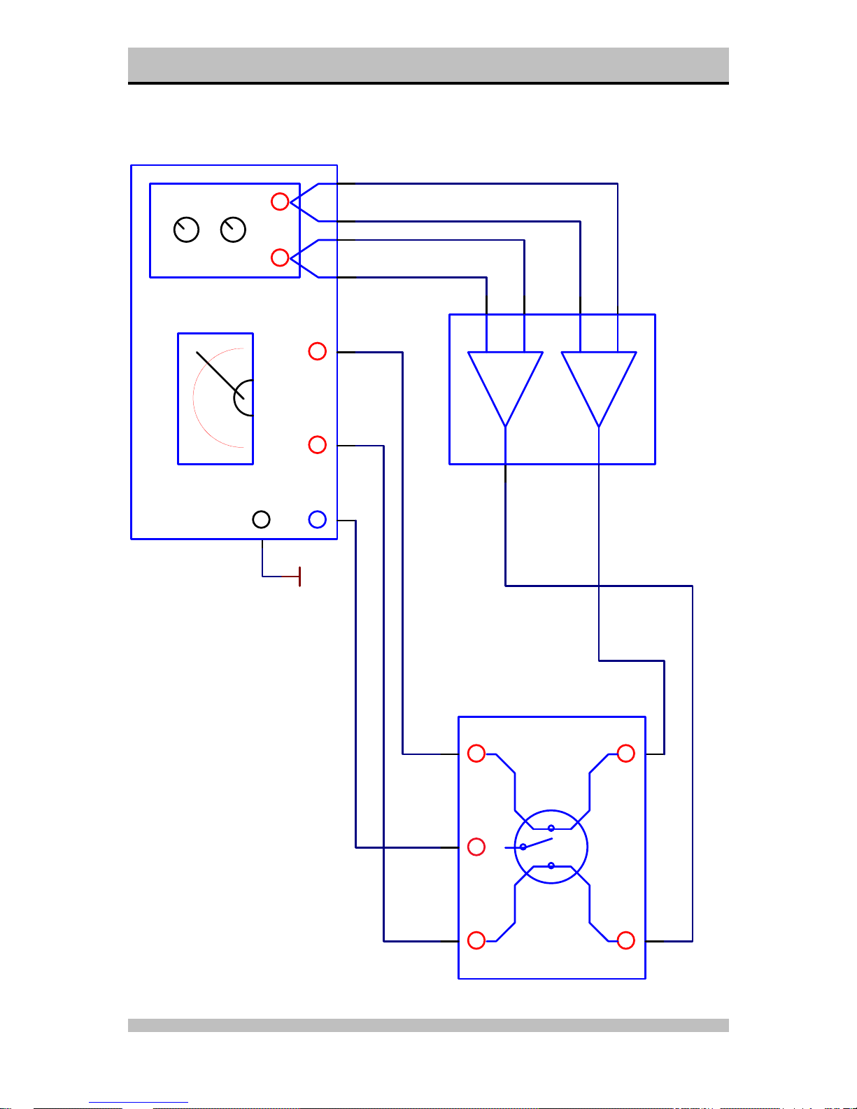
Necessary Equipment
To properly service the Project Ten you need some
specific measurement equipment and use a specific
set-up.
For the correct measurement set-up and hook-up
please refer to the drawing titled “Connection
Connection diagram… at pages 14 and 15.
q 2x millivolt-meter (Ri >1 MΩ)
q 2x non-inductive load resistor 8 Ω / 100 Watt
q 1x harmonic distortion analyser
(internal distortion <0.0005%, measured
without filters)
q 1x 2-channel oscilloscope
(minimum bandwidth >60 MHz)
q 1x connection unit / switch box
(to connect scope, resistors and amp outputs to
distortion analyser)
q 2x shorting connector
(for balanced pre-amp inputs)
q 2x balanced cable set
(to connect distortion analyser to Project Ten)
Page 10

SPHINX Project Ten Service Manual
10
8. ADJUSTMENT PROCEDURES
The Project Ten is an integrated amplifier, meaning
the pre-amp and power amp sections are combined
into one cabinet.
The Project Ten only has two parameters for each
channel (so four in total) that might need
adjustment:
- Bias: to set the bias current and bias voltage of
the amplifier for normal use.
- Offset: to set the DC-offset voltage of the
output.
These adjustments might be necessary when the
amplifier has been used for a period of time (and
settings have changed due to ageing) or when a
part of the Project Ten have been replaced.
Attention:
When re-adjusting any setting please ensure that
there is no loudspeaker connected to the output!
Otherwise the loudspeaker may be seriously
damaged.
Attention:
The amplifier is able to generate high output
voltages of over + or -40 V.
Please be very careful during the adjustments!
The Project Ten is a two channel amplifier.
After removing the top cover plate you will see the
Left and Right Channels clearly marked.
The power transistors are mounted underneath the
heatsinks.
Bias
With this procedure you set the proper bias level for
the power transistors. This ensures their Class A
operation at low power levels.
Connect the amplifier according to the drawing
“Connection Diagram Bias Adjustment” (page 14).
The input of the amplifier must be shorted (by way
of the MUTE function of the oscillator).
• Switch the amplifier ON and wait until it has
reached the proper working temperature (this
takes an hour).
• Set the millivolt-meter to the DC-range.
• Place the two measuring clips of the meter
across one of the emitter resistors
Left: R267, R271, R273, R277
Right: R467, R471, R473, R477
(refer to schematic in Pj10main.PDF).
These resistors are positioned to the left of the
power supply condensers.
• The level for each should be 40 mV DC
(±2 mV).
If not: adjust potmeter P202 (Left) or potmeter
P402 (Right) until the level is 40 mV.
• Switch the oscillator on and set it to 1 kHz and a
level of 0 dBu.
• Check the distortion with a THD analyser: it
should be conform the specified values (0.01%
IHF-A @ 1 – 20 kHz @ 80 W into 8 ohm).
• If this is correct the procedure is finished.
• You may now switch off the amplifier or continue
with another adjustment procedure.
Page 11

SPHINX Project Ten Service Manual
11
Offset
The Offset adjustment procedure minimises the DC
offset value of the amplifier output. This DC offset is
important when capacitive loads are used, such as
electrostatic loudspeakers. These loudspeakers
often use a very low-impedance step-up
transformer. The amplifier ‘sees’ this load as a
short for the DC voltage.
Connect the amplifier according to the drawing
“Connection Diagram Offset Adjustment” (page 15).
The input of the amplifier must be shorted (by way
of the MUTE function of the oscillator)..
• Switch the amplifier ON and wait until it has
reached the proper working temperature (this
takes an hour).
• Set the millivolt-meter to the DC-range.
• Place the measurement clips of the meter over
the output terminal.
• The level should not exceed +5 or -5 mV DC.
If not: adjust potmeter P201 (Left) or P401
(Right) until the level is within this range.
• Switch the oscillator on and set it to 1 kHz and a
level of 0 dBu.
• Check the distortion with a THD analyser: it
should be conform the specified values (0.01%
IHF-A @ 1 - 20 kHz).
• If this is correct the procedure is finished.
• You may now switch off the amplifier or continue
with another adjustment procedure.
Attention:
Do not connect speakers on the Project 10 when
adjusting the offset.
Please be careful during the adjustments!
Page 12

SPHINX Project Ten Service Manual
12
9. PROBLEMS AND SOLUTIONS
At the moment of writing the Project Ten has no
known specific problems.
If in the future you encounter any problem(s) you
may enter the info in this table. This table can then
be used for future reference.
Please also send (by fax or e-mail) the specific
information to the Sphinx International Service
Department (see page 3): this info can then be
added to the general database to aid others.
Problem Cause Solution Refer to
page…
Amplifier doesn’t work Fuses are blowed (short circuit
output)
Replace fuses type 3.15A SB Page 18
Page 13

SPHINX Project Ten Service Manual
13
10. DIAGRAMS AND PARTS LISTS
The next pages contain the front and rear panel lay-out and a complete set of schematic drawings including the
associated parts lists (if applicable).
Connection diagram bias adjustment .........................................................................................................14
Connection diagram offset adjustment.......................................................................................................15
Connections main board and display board of Project 10 ..........................................................................16
General overview Project 10 ......................................................................................................................17
Project 10 power supply and input selection ..............................................................................................18
Project 10 volume board.............................................................................................................................19
Project 10 amplifier left...............................................................................................................................20
Project 10 amplifier right............................................................................................................................. 21
Project 10 control .......................................................................................................................................22
PCB drawings of Project 10........................................................................................................................23
Part list .......................................................................................................................................................24
Page 14
SPHINX Project Ten Service Manual
14
Connection diagram bias adjustment
out1 out2
inp2
inp1
gnd
THD
Amplitude
Frequency
Oscillator
THD out
(+) (-) (+) (-)
THD ANALYZER
out1 out2
inp2inp1
Scoop
SWITCH-BOX
Right
Left
(+)
(+)
(-)
(-)
Amplfier (30x)
A
B
Project 10
GND
Page 15

SPHINX Project Ten Service Manual
15
Connection diagram offset adjustment
out1 out2
inp2
inp1
gnd
THD
Amplitude
Frequency
Oscillator
THD out
(+) (-) (+) (-)
THD ANALYZER
out1 out2
inp2inp1
Scoop
SWITCH-BOX
Right
Left
(+)
(+)
(-)
(-)
Amplfier (30x)
A
B
Project 10
GND
mVmV
GND
Page 16

SPHINX Project Ten Service Manual
16
Connections main board and display board of Project 10
+12V
+5V
GND
L2
L1
TU
CD
TM
TS
STB
VOL1
VOL2
MU
12V-SW
IN-L
IN-R
PRE-L
PRE-R
+12V
+5V
GND
L2
L1
TU
CD
TM
TS
STB
VOL1
VOL2
MU
12V-SW
IN-L
IN-R
PRE-L
PRE-R
+12V
+5V
GND
L1
L2
TU
CD
TM
TS
STB
MU
VOL1
VOL2
12V-SW
+12V
+5V
GND
L1
L2
TU
CD
TM
TS
STB
MU
VOL1
VOL2
12V-SW
PJ10 main board PJ10 control board
IN-L
IN-R
PRE-L
PRE-R
GND
VOL1
VOL2
IN-L
IN-R
PRE-L
PRE-R
GND
VOL1
VOL2
PJ10 volume board
IN-L
IN-R
PRE-L
PRE-R
GND
+12V
+5V
GND
L1
L2
TU
CD
TM
TS
STB
MU
VOL1
VOL2
+12V
+5V
GND
L1
L2
TU
CD
TM
TS
STB
MU
VOL1
VOL2
12V-SW 12V-SW
VOL1
VOL2
GND
FUSE
MAINS SWITCH
MAINS FILTER
TRANSFORMER
CN103 (RED)
CN104 (YELLOW)
CN105 (BLUE)
CN106 (GRAY)
CN107 (GREEN)
CN108 (PURPLE)
MAINS INLET 33V
33V
14V
IN-L
IN-R
PRE-L
PRE-R
PURPLE
ORANGE
Page 17

SPHINX Project Ten Service Manual
17
General overview Project 10
PRE-L
+44V
GND
-44V
OUT-L
-15V-L
+15V-L
PRE-L
+44V
GND
-44V
OUT-L
-15V-L
+15V-L
GND
+44V
PRE-R
-44V
OUT-R
-15V
+15V
GND
+44V
PRE-R
-44V
OUT-R
-15V
+15V
+12V
+5V
+44V
GND
-44V
MUTE
STB
TM
L1
CD
L2
TU
OUT-L
OUT-R
MU
+12V
+5V
+44V
GND
-44V
MUTE
STB
TM
L1
CD
L2
TU
OUT-L
OUT-R
MU
+12V
GND
IN-L
IN-R
OUT-L
OUT-R
MUTE
-15V-L
+15V-R
-15V-R
+15V-L
+12V
GND
IN-L
IN-R
OUT-L
OUT-R
MUTE
-15V-L
+15V-R
-15V-R
+15V-L
+12V
+5V
+44V
-44V
GND
STB
PRE-L
OUT-L
PRE-R
OUT-R
-44V
GND
+44V
IN-L
IN-R
OUT-L
OUT-R
TM
CD
L1
L2
TU
+12V
GND
OUT-L
OUT-R
PJ10 left channel PJ10 right channel
PJ10 input/outputPJ10 power supply
+15V-L
-15V-L
+15V-R
-15V-R
+15V-L
-15V-L
+15V-R
-15V-R
MU
MUTE MUTE
+44V
GND
-44V
Page 18

SPHINX Project Ten Service Manual
18
Project 10 power supply and input selection
Z1
3.15A
Z2
3.15A
B101
B102
+
C109+C110+C111+C112
+
C113+C114+C115+C116
GND
+44V
-44V
8 X 6800U/50V
-44V
GND
+44V
B103
R111
1R00
+
C107
1000U
VoutVin
GND
Q102
7812
C108
100N
+
C106
47U/25V
R103
10K0
R102
10K0
R106
10K0
R105
10K0
R108
100K
R107
100K
R104
22K1
R109
47K5
R101
10K0
R110
33K2
VoutVin
GND
Q101
7805
C102
100N
+
C101
C16V/1U5
T107
BC556
T101
BC546
T105
BC546
T106
BC546
T104
BC546
REL103A
TUNER
REL104A
LINE1
REL105A
LINE2
D105D102 D104D103
1
2
3
4
5
6
7
8
9
10
11
12
13
14
15
16
17
18
CN102
18PIN
REL101A
TAPE-MON
D101
REL102A
CD
+
C105
47U/25V
+
C104
330U/50V
+
C103
330U/50V
D106
1N4148
STB
+12V
+5V
MU
MUTE
+12V
+5V
MU
+12V
TS
GND
STB
TM
+5V
CD
+5V
TU
VOL2
L1
VOL1
L2
12V-SW
TM
CD
TU
L1
L2
12
OPTO201B
12
OPTO401B
OPTO101
R112
1K00
OUT-L
OUT-R
35V
8 X 220pF STYROFLEX
125V of 160V
op onderzijde solderen
D101 t/m D106 : 1N4148
GND
+12V
GND
+44V
+12V
+5V
GND
-44V
D107
6V8
12V-SW
CN103
CN104
CN105
CN106
CN107
CN108
T102
BD880
T103
BC517
heatsink
1
2
CN109
+5V
TS
temperature sensor (optional)
REL101B
REL102B
REL103B
REL104B
REL105B
REL101C
REL102C
REL103C
REL104C
REL105CCN112B
CN111A
CN110A
CN112A
CN111B
CN110B
R301 4K75
R501 4K75
R479
1K00
R480
1K00
R481
100R
R280
1K00
R281
100R
R279
1K00
S101A
S101B
2
3
6
74
1
5
IC301
SSM2143
R303
1K50
R304
1K50
R302
100R
+
C302
47u
+
C303
47u
C301
100n
C304
100n
GND
GND
GND
132
CN113
XLR
2
3
6
74
1
5
IC501
SSM2143
R503
1K50
R504
1K50
R502
100R
+
C502
47u
+
C503
47u
C501
100n
C504
100n
GND
GND
132
CN114
XLR
GND
REL106
MAIN-L MAIN-R
GND
D108
1N4148
+12V
MUTE
CN115
GND
OUT-L
OUT-R
to speaker terminals
+15V-R
-15V-R
+15V-R
-15V-R
GND
-15V-L
+15V-L
+15V-L
-15V-L
headphone jack
+15V-L
+15V-R
GND
-15V-L
-15V-R
+12V
+12V
IN-R
IN-L
to volume board
XLR <-> CINCH
OUT-L OUT-R
OUT-R
OUT-L
MUTE
MUTE
Page 19

SPHINX Project Ten Service Manual
19
Project 10 volume board
M
P801A
solderconnection on volume board
P801B
P801C
solderconnection on main board
PRE-R
PRE-L
IN-R
IN-L
GND
VOL1
VOL2
Page 20

SPHINX Project Ten Service Manual
20
Project 10 amplifier left
R200
2K21
R201
47K5
R203
2K21
R205
1K50
R207
2K21
R204
1K00
R206
182R
R214
681R
R211
100R
R216
100R
R202
22K1
R209
3K32
R217
10R0
R208
221R
T201
K389
T204
C2240
T202
C2240
T203
C2240
T206
C2240
T208
C2240
T209
C2240
T224
C2240
T219
C2240
T214
C2240
T215
C2240
T220
C2240T216
C2240
C201
330P
LD201
LD202
LD203
GND
T213
A970
T221
A970
T223
A970
T217
A970
T207
A970
T218
A970
T210
A970
T222
A970
T205
A970
C200
220P
C222
47P
C202
22P
GND
GND
R213
100R
R215
100R
R210
10K0
R212
47K5
GND
P201
200
R218
221
R219
47R5
R220
47R5
R221
1K00
R224
10K0
C207
1N
GND
R222
10R0
R231
1K00
R226
1K00
R239
47R5
R236
47R5
R225
10K
R229
221R
R241
1K00
R237
1K00
R233
47R5
R235
1K00
R242
47R5
R232
1K00
R234
1K00
R228
10K
R238
1K00
R230
221R
R240
1K00
R223
10R0
R227
1K00
C203
100N
C204
100N
+
C205
1000U
+
C209
1000U
+
C206
47U
+
C210
47U
+
C212
47U
+
C208
47U
+
C213
47U
+
C211
47U
Z201
16V
LD204
Z202
16V
LD205
C214
330P
C215
330P
R246
47R5
R247
1K82
R265
47K5
T225
A1145
T226
C2705
R249
332R
LD208
LD206
D201
R250
332R
R251
3K92
R255
47R5
R252
4K75
P202
10K
+
C220
10U
54
OPTO201A
SFH601-3
R243
10R
C216
33P
C217
220P
GND
LD207
LD209
R248
95K3
R271
1R0
R267
1R0
R276
10R0
R272
10R0
R275
10K0
R274
10K0
R277
1R0
R263
47R5
R258
47R5
R266
10R0
R269
10K0
R268
10K0
R270
10R0
R260
221R
R254
47R5
R264
221R
R259
221R
R256
6R81
R257
6R81
R261
6R81
R262
6R81
R253
47R5
T233
A1302
T232
A1302
T231
A1306
T229
C3298
T234
C3281
T235
C3281
T227
C3423
T228
A1360
C223
100P
C224
100P
R273
1R0
R278
15R
D202
1N5407
D203
1N5407
C221
100N
GND
GND GND
GND
GND
GNDGND
PRE-L
GND
-44V
+44V
from volume board
to output relay
+44V
-44V
GND
+15V-L
-15V-L
4W
+15V-L
-15V-L
IN-L
OUT-L
IN-L
+44V
+15V-L
GND
-15V-L
-44V
OUT-L
P201
P202
OFFSET
BIAS
POT.METER FUNCTION
OUT-L
T230
BC517
BD901
T212
BD902
Page 21

SPHINX Project Ten Service Manual
21
Project 10 amplifier right
R400
2K21
R401
47K5
R403
2K21
R405
1K50
R407
2K21
R404
1K00
R406
182R
R414
681R
R411
100R
R416
100R
R402
22K1
R409
3K32
R417
10R0
R408
221R
T401
K389
T404
C2240
T402
C2240
T403
C2240
T406
C2240
T408
C2240
T409
C2240
T424
C2240
T419
C2240
T414
C2240
T415
C2240
T420
C2240T416
C2240
C401
330P
LD401
LD402
LD403
GND
T413
A970
T421
A970
T423
A970
T417
A970
T407
A970
T418
A970
T410
A970
T422
A970
T405
A970
C400
220P
C422
47P
C402
22P
GND
GND
R413
100R
R415
100R
R410
10K0
R412
47K5
GND
P401
200
R418
221
R419
47R5
R420
47R5
R421
1K00
R424
10K0
C407
1N
GND
R422
10R0
R431
1K00
R426
1K00
R439
47R5
R436
47R5
R425
10K
R429
221R
R441
1K00
R437
1K00
R433
47R5
R435
1K00
R442
47R5
R432
1K00
R434
1K00
R428
10K
R438
1K00
R430
221R
R440
1K00
R423
10R0
R427
1K00
C403
100N
C404
100N
+
C405
1000U
+
C409
1000U
+
C406
47U
+
C410
47U
+
C412
47U
+
C408
47U
+
C413
47U
+
C411
47U
Z401
16V
LD404
Z402
16V
LD405
C414
330P
C415
330P
R446
47R5
R447
1K82
R465
47K5
T425
A1145
T426
C2705
R449
332R
LD408
LD406
D401
R450
332R
R451
3K92
R455
47R5
R452
4K75
P402
10K
+
C420
10U
54
OPTO401A
SFH601-3
R443
10R
C416
33P
C417
220P
GND
LD407
LD409
R448
95K3
R471
1R0
R467
1R0
R476
10R0
R472
10R0
R475
10K0
R474
10K0
R477
1R0
R463
47R5
R458
47R5
R466
10R0
R469
10K0
R468
10K0
R470
10R0
R460
221R
R454
47R5
R464
221R
R459
221R
R456
6R81
R457
6R81
R461
6R81
R462
6R81
R453
47R5
T433
A1302
T432
A1302
T431
A1306
T429
C3298
T434
C3281
T435
C3281
T427
C3423
T428
A1360
C423
100P
C424
100P
R473
1R0
R478
15R/4W
D402
1N5407
D403
1N5407
C421
100N
GND
GND GND
GND
GND
GNDGND
PRE-R
GND
OUT-R
-44V
+44V
from volume board
to output relay
+44V
-44V
GND
+15V
-15V
IN-R
OUT-R
+44V
+15V-R
GND
-15V-R
-44V
IN-R
+15V-R
OUT-R
-15VR-
P401
P402
OFFSET
BIAS
POT.METER FUNCTION
T430
BC517
T412
BD902
BD901
Page 22

SPHINX Project Ten Service Manual
22
Project 10 control
Xtal
10
EXtal
11
MD1
12
MD0
13
NMI
14
VCC
15
STBY
16
GND
17
P40
19
P41
20
P42
21
P43
22
P44
23
P45
24
P46
25
P47
26
nc
18
P5027P5128P5229P5330P5431P5532P7033P7134nc35P7236P7337P7438P75/WR39P76/RD40P7741VCC42P27
43
RES
9
P668P657P646P635P624P613P60
2nc1
P3061P3162P3263P3364P3465P3566P3667P37
68
P26
44
P25
45
P24
46
P23
47
P22
48
P21
49
P20
50
nc
51
GND
52
P17
53
P16
54
P15
55
P14
56
P13
57
P12
58
P11
59
P10
60
H8
U1
H8/325
C1
33p
C2
33p
C3
100n
GND
+5V
+5V
1
2
3
4
5
6
7
8
9
10
11
12
13
14
15
16
17
18
CN1
LINE2
VOL1
LINE1
VOL2
TUNER
+5V
CD
+5V
TAPE-MON
STANDBY
GND
GND
GND
+12V-SW
T-SENSOR
+12V LED
+12V LED
MUTE
IN1
1
IN2
2
IN3
3
IN4
4
IN5
5
IN6
6
IN7
7
IN8
8
GND
9
OUT8
11
OUT7
12
OUT6
13
OUT5
14
OUT4
15
OUT3
16
OUT2
17
OUT1
18
K
10
U2
ULN2804
GND
LD3LD7LD2 LD4 LD6LD5
LD1
R2
475R
R3
475R
R4
1K50
R5
475R
R6
1K50
+12V
2 1
S1
standby
2 1
S2
mute
2 1
S3
cd
2 1
S4
tuner
2 1
S5
line1
2 1
S6
line2
2 1
S7
tape-mon
V+
2
D
1
GND
3
IR
IR1
SFH506-38
R7
10R0
R8
47K5
+
C4
47u
+5V
T2
C2240 T3
C2240
T4
A970
T5
A970
GND
+5V
+
U3
TL7757
X1
8MHz
R1
10R0R910R0
C6
100N
GND
R10
100K
J1
JUMPER CLOSED OPEN
SERVICE
NORMAL JUMPER SETTINGS
PJ10
+
C5
100u
GND
+5V
+5V
GND
+12V
VOL2 VOL1
L2
VOL1
L1
VOL2
TU
CD
TM
STB
TS
MU
MU
+5V
GND
+5V
MU
TM
CD
TU
L1
L2
to main board
J1
JUMPER
25V
standby
12V-SW
GND
STB
Page 23

SPHINX Project Ten Service Manual
23
PCB drawings of Project 10
Because there is a significant image-quality loss during the conversion of the drawings, the PCB-drawing is
located in a separate file.
This file is in PDF-format (Adobé Acrobat 3.0 Reader).
• Pj10main.PDF for Mainboard
• Pj10disl.PDF for Display
Page 24

SPHINX Project Ten Service Manual
24
Parts list
Designator Part Type Description
B101 BR102 Bridge rectifier
B102 BR102 Bridge rectifier
B103 WO2M Bridge rectifier
C1 33pF Ceramic capacitor
C101 1.5uF/16V Electrolytic capacitor
C102 100nF MKT capacitor
C103 330uF/50V Electrolytic capacitor
C104 330uF/50V Electrolytic capacitor
C105 47uF/25V Electrolytic capacitor
C106 47uF/25V Electrolytic capacitor
C107 1000uF Electrolytic capacitor
C108 100nF MKT capacitor
C109 6800uF/50V Electrolytic capacitor
C110 6800uF/50V Electrolytic capacitor
C111 6800uF/50V Electrolytic capacitor
C112 6800uF/50V Electrolytic capacitor
C113 6800uF/50V Electrolytic capacitor
C114 6800uF/50V Electrolytic capacitor
C115 6800uF/50V Electrolytic capacitor
C116 6800uF/50V Electrolytic capacitor
C2 33pF Ceramic capacitor
C200 220pF Styroflex capacitor
C201 330pF Styroflex capacitor
C202 22pF Ceramic capacitor
C203 100nF MKT capacitor
C204 100nF MKT capacitor
C205 1000uF Electrolytic capacitor
C206 47uF/25V Electrolytic capacitor
C207 1nF MKT capacitor
C208 47uF/25V Electrolytic capacitor
C209 1000uF Electrolytic capacitor
C210 47uF/25V Electrolytic capacitor
C211 47uF/25V Electrolytic capacitor
C212 47uF/25V Electrolytic capacitor
C213 47uF/25V Electrolytic capacitor
C214 330pF Styroflex capacitor
C215 330pF Styroflex capacitor
C216 33pF Styroflex capacitor
C217 220pF Styroflex capacitor
C220 10uF Electrolytic capacitor
C221 100nF MKT capacitor
C222 47pF Styroflex capacitor
C223 100pF Styroflex capacitor
C224 100pF Styroflex capacitor
C3 100nF MKT capacitor
C301 100nF MKT capacitor
Page 25

SPHINX Project Ten Service Manual
25
Designator Part Type Description
C302 47uF/25V Electrolytic capacitor
C303 47uF/25V Electrolytic capacitor
C304 100nF MKT capacitor
C4 47uF/16V Electrolytic capacitor
C400 220pF Styroflex capacitor
C401 330pF Styroflex capacitor
C402 22pF Ceramic capacitor
C403 100nF MKT capacitor
C404 100nF MKT capacitor
C405 1000uF Electrolytic capacitor
C406 47uF Electrolytic capacitor
C407 1nF MKT capacitor
C408 47uF Electrolytic capacitor
C409 1000uF Electrolytic capacitor
C410 47uF Electrolytic capacitor
C411 47uF Electrolytic capacitor
C412 47uf Electrolytic capacitor
C413 47uF Electrolytic capacitor
C414 330pF Styroflex capacitor
C415 330pF Styroflex capacitor
C416 33pF Styroflex capacitor
C417 220pF Styroflex capacitor
C420 10uF Electrolytic capacitor
C421 100nF MKT capacitor
C422 47pF Styroflex capacitor
C423 100pF Styroflex capacitor
C424 100pF Styroflex capacitor
C5 100uF/25V Electrolytic capacitor
C501 100nF MKT capacitor
C502 47uF Electrolytic capacitor
C503 47uF Electrolytic capacitor
C504 100nF MKT capacitor
C6 100nF MKT capacitor
CN1 18PIN 18 pin connector
CN102 18PIN 18 pin connector
CN103 FASTON Flat-cable connector
CN104 FASTON Flat-cable connector
CN105 FASTON Flat-cable connector
CN106 FASTON Flat-cable connector
CN107 FASTON Flat-cable connector
CN108 FASTON Flat-cable connector
CN110 CINCH2P Cinch connector
CN111 CINCH2P Cinch connector
CN112 CINCH2P Cinch connector
CN113 NC3FPP XLR connector
CN114 NC3FPP XLR connector
D101 1N4148 Diode
D102 1N4148 Diode
Page 26

SPHINX Project Ten Service Manual
26
Designator Part Type Description
D103 1N4148 Diode
D104 1N4148 Diode
D105 1N4148 Diode
D106 1N4148 Diode
D107 6V8 Zener diode
D108 1N4148 Diode
D202 1N5407 Diode
D203 1N5407 Diode
D402 1N5407 Diode
D403 1N5407 Diode
IC301 SSM2143 IC
IC501 SSM2143 IC
IR1 SFH 506-38 Infrared receiver
J1 Jumper Jumper
LD1 LED red LED red
LD2 LED red LED red
LD201 LED red LED red
LD202 LED red LED red
LD203 LED red LED red
LD204 LED red LED red
LD205 LED red LED red
LD206 LED red LED red
LD207 LED red LED red
LD208 LED red LED red
LD209 LED red LED red
LD3 LED red LED red
LD4 LED red LED red
LD401 LED red LED red
LD402 LED red LED red
LD403 LED red LED red
LD404 LED red LED red
LD405 LED red LED red
LD406 LED red LED red
LD407 LED red LED red
LD408 LED red LED red
LD409 LED red LED red
LD5 LED red LED red
LD6 LED red LED red
LD7 LED red LED red
OPTO101 OPTOUT Optical output
OPTO201 SFH601-3 Opto-coupler
OPTO401 SFH601-3 Opto-coupler
P201 200R Trim pot.
P202 10K Trim pot.
Page 27

SPHINX Project Ten Service Manual
27
Designator Part Type Description
P401 200R Trim pot.
P402 10K Trim pot.
Q101 L7805CV Voltage stabiliser
Q102 L7812CV Voltage stabiliser
R1 10R0 Resistor MRS25
R10 100K Resistor MRS25
R101 10K0 Resistor MRS25
R102 10K0 Resistor MRS25
R103 10K0 Resistor MRS25
R104 22K1 Resistor MRS25
R105 10K0 Resistor MRS25
R106 10K0 Resistor MRS25
R107 100K Resistor MRS25
R108 100K Resistor MRS25
R109 47K5 Resistor MRS25
R110 33K2 Resistor MRS25
R111 1R00 Resistor MRS25
R112 1K00 Resistor MRS25
R2 475R Resistor MRS25
R200 2K21 Resistor MRS25
R201 47K5 Resistor MRS25
R202 22K1 Resistor MRS25
R203 2K21 Resistor MRS25
R204 1K00 Resistor MRS25
R205 1K50 Resistor MRS25
R206 182R Resistor MRS25
R207 2K21 Resistor MRS25
R208 221R Resistor MRS25
R209 3K32 Resistor MRS25
R210 10K0 Resistor MRS25
R211 100R Resistor MRS25
R212 47K5 Resistor MRS25
R213 100R Resistor MRS25
R214 681R Resistor MRS25
R215 100R Resistor MRS25
R216 100R Resistor MRS25
R217 10R0 Resistor MRS25
R218 221R Resistor MRS25
R219 47R5 Resistor MRS25
R220 47R5 Resistor MRS25
R221 1K00 Resistor MRS25
R222 10R0 Resistor MRS25
R223 10R0 Resistor MRS25
R224 10K0 Resistor MRS25
R225 10K Resistor MRS25
R226 1K00 Resistor MRS25
R227 1K00 Resistor MRS25
R228 10K Resistor MRS25
R229 221R Resistor MRS25
Page 28

SPHINX Project Ten Service Manual
28
Designator Part Type Description
R230 221R Resistor MRS25
R231 1K00 Resistor MRS25
R232 1K00 Resistor MRS25
R233 47R5 Resistor MRS25
R234 1K00 Resistor MRS25
R235 1K00 Resistor MRS25
R236 47R5 Resistor MRS25
R237 1K00 Resistor MRS25
R238 1K00 Resistor MRS25
R239 47R5 Resistor MRS25
R240 1K00 Resistor MRS25
R241 1K00 Resistor MRS25
R242 47R5 Resistor MRS25
R243 10R Resistor MRS25
R246 47R5 Resistor MRS25
R247 1K82 Resistor MRS25
R248 95K3 Resistor MRS25
R249 332R Resistor MRS25
R250 332R Resistor MRS25
R251 3K92 Resistor MRS25
R252 4K75 Resistor MRS25
R253 47R5 Resistor MRS25
R254 47R5 Resistor MRS25
R255 47R5 Resistor MRS25
R256 6R81 Resistor MRS25
R257 6R81 Resistor MRS25
R258 47R5 Resistor MRS25
R259 221R Resistor MRS25
R260 221R Resistor MRS25
R261 6R81 Resistor MRS25
R262 6R81 Resistor MRS25
R263 47R5 Resistor MRS25
R264 221R Resistor MRS25
R265 47K5 Resistor MRS25
R266 10R0 Resistor MRS25
R267 1R0 Resistor MRS25
R268 10K0 Resistor MRS25
R269 10K0 Resistor MRS25
R270 10R0 Resistor MRS25
R271 1R0 Resistor MRS25
R272 10R0 Resistor MRS25
R273 1R0 Resistor MRS25
R274 10K0 Resistor MRS25
R275 10K0 Resistor MRS25
R276 10R0 Resistor MRS25
R277 1R0 Resistor MRS25
R278 15R Resistor MRS25
R279 1K00 Resistor MRS25
R280 1K00 Resistor MRS25
R281 100R Resistor MRS25
Page 29

SPHINX Project Ten Service Manual
29
Designator Part Type Description
R3 475R Resistor MRS25
R301 4K75 Resistor MRS25
R302 100R Resistor MRS25
R303 1K50 Resistor MRS25
R304 1K50 Resistor MRS25
R4 1K50 Resistor MRS25
R400 2K21 Resistor MRS25
R401 47K5 Resistor MRS25
R402 22K1 Resistor MRS25
R403 2K21 Resistor MRS25
R404 1K00 Resistor MRS25
R405 1K50 Resistor MRS25
R406 182R Resistor MRS25
R407 2K21 Resistor MRS25
R408 221R Resistor MRS25
R409 3K32 Resistor MRS25
R410 10K0 Resistor MRS25
R411 100R Resistor MRS25
R412 47K5 Resistor MRS25
R413 100R Resistor MRS25
R414 681R Resistor MRS25
R415 100R Resistor MRS25
R416 100R Resistor MRS25
R417 10R0 Resistor MRS25
R418 221R Resistor MRS25
R419 47R5 Resistor MRS25
R420 47R5 Resistor MRS25
R421 1K00 Resistor MRS25
R422 10R0 Resistor MRS25
R423 10R0 Resistor MRS25
R424 10K0 Resistor MRS25
R425 10K Resistor MRS25
R426 1K00 Resistor MRS25
R427 1K00 Resistor MRS25
R428 10K Resistor MRS25
R429 221R Resistor MRS25
R430 221R Resistor MRS25
R431 1K00 Resistor MRS25
R432 1K00 Resistor MRS25
R433 47R5 Resistor MRS25
R434 1K00 Resistor MRS25
R435 1K00 Resistor MRS25
R436 47R5 Resistor MRS25
R437 1K00 Resistor MRS25
R438 1K00 Resistor MRS25
R439 47R5 Resistor MRS25
R440 1K00 Resistor MRS25
R441 1K00 Resistor MRS25
R442 47R5 Resistor MRS25
R443 10R Resistor MRS25
Page 30

SPHINX Project Ten Service Manual
30
Designator Part Type Description
R446 47R5 Resistor MRS25
R447 1K82 Resistor MRS25
R448 95K3 Resistor MRS25
R449 332R Resistor MRS25
R450 332R Resistor MRS25
R451 3K92 Resistor MRS25
R452 4K75 Resistor MRS25
R453 47R5 Resistor MRS25
R454 47R5 Resistor MRS25
R455 47R5 Resistor MRS25
R456 6R81 Resistor MRS25
R457 6R81 Resistor MRS25
R458 47R5 Resistor MRS25
R459 221R Resistor MRS25
R460 221R Resistor MRS25
R461 6R81 Resistor MRS25
R462 6R81 Resistor MRS25
R463 47R5 Resistor MRS25
R464 221R Resistor MRS25
R465 47K5 Resistor MRS25
R466 10R0 Resistor MRS25
R467 1R0 Resistor MRS25
R468 10K0 Resistor MRS25
R469 10K0 Resistor MRS25
R470 10R0 Resistor MRS25
R471 1R0 Resistor MRS25
R472 10R0 Resistor MRS25
R473 1R0 Resistor MRS25
R474 10K0 Resistor MRS25
R475 10K0 Resistor MRS25
R476 10R0 Resistor MRS25
R477 1R0 Resistor MRS25
R478 15R/4W Resistor MRS25
R479 1K00 Resistor MRS25
R480 1K00 Resistor MRS25
R481 100R Resistor MRS25
R5 475R Resistor MRS25
R501 4K75 Resistor MRS25
R502 100R Resistor MRS25
R503 1K50 Resistor MRS25
R504 1K50 Resistor MRS25
R6 1K50 Resistor MRS25
R7 10R0 Resistor MRS25
R8 47K5 Resistor MRS25
R9 10R0 Resistor MRS25
REL101 Relay Relay
REL102 Relay Relay
REL103 Relay Relay
REL104 Relay Relay
Page 31

SPHINX Project Ten Service Manual
31
Designator Part Type Description
REL105 Relay Relay
S1 Switch Switch
S2 Switch Switch
S3 Switch Switch
S4 Switch Switch
S5 Switch Switch
S6 Switch Switch
S7 Switch Switch
T101 BC546 Transistor
T102 BD880 Transistor
T103 BC517 Transistor
T104 BC546 Transistor
T105 BC546 Transistor
T106 BC546 Transistor
T107 BC556 Transistor
T2 T2SC2240 Transistor
T201 K389 DUAL N-JFET
T202 2SC2240 Transistor
T203 2SC2240 Transistor
T204 2SC2240 Transistor
T205 2SA970 Transistor
T206 2SC2240 Transistor
T207 2SA970 Transistor
T208 2SC2240 Transistor
T209 2SC2240 Transistor
T210 2SA970 Transistor
T211 BD901 Transistor
T212 BD902 Transistor
T213 2SA970 Transistor
T214 2SC2240 Transistor
T215 2SC2240 Transistor
T216 2SC2240 Transistor
T217 2SA970 Transistor
T218 2SA970 Transistor
T219 2SC2240 Transistor
T220 2SC2240 Transistor
T221 2SA970 Transistor
T222 2SA970 Transistor
T223 2SA970 Transistor
T224 2SC2240 Transistor
T225 2SA1145 Transistor
T226 2SC2705 Transistor
T227 2SC3423 Transistor
T228 2SA1360 Transistor
T229 2SC3298 Transistor
T230 BC517 Transistor
T231 2SA1306 Transistor
T232 2SA1302 Transistor
Page 32

SPHINX Project Ten Service Manual
32
Designator Part Type Description
T233 2SA1302 Transistor
T234 2SC3281 Transistor
T235 2SC3281 Transistor
T3 T2SC2240 Transistor
T4 T2SA970 Transistor
T401 K389 DUAL N-JFET
T402 2SC2240 Transistor
T403 2SC2240 Transistor
T404 2SC2240 Transistor
T405 2SA970 Transistor
T406 2SC2240 Transistor
T407 2SA970 Transistor
T408 2SC2240 Transistor
T409 2SC2240 Transistor
T410 2SA970 Transistor
T411 BD901 Transistor
T412 BD902 Transistor
T413 2SA970 Transistor
T414 2SC2240 Transistor
T415 2SC2240 Transistor
T416 2SC2240 Transistor
T417 2SA970 Transistor
T418 2SA970 Transistor
T419 2SC2240 Transistor
T420 2SC2240 Transistor
T421 2SA970 Transistor
T422 2SA970 Transistor
T423 2SA970 Transistor
T424 2SC2240 Transistor
T425 2SA1145 Transistor
T426 2SC2705 Transistor
T427 2SC3423 Transistor
T428 2SA1360 Transistor
T429 2SC3298 Transistor
T430 BC517 Transistor
T431 2SA1306 Transistor
T432 2SA1302 Transistor
T433 2SA1302 Transistor
T434 2SC3281 Transistor
T435 2SC3281 Transistor
T5 T2SA970 Transistor
U1 H8/325 IC
U2 ULN2804 IC
U3 TL7757 IC
X1 8MHz X-TAL
Z1 T3.15A Fuse
Z2 T3.15A Fuse
Page 33

SPHINX Project Ten Service Manual
33
Designator Part Type Description
Z201 16V Zener diode
Z202 16V Zener diode
Z401 16V Zener diode
Z402 16V Zener diode
 Loading...