

Page 1
1.
SERVICE MANUAL
MYTH 3
INTEGRATED
STEREO AMPLIFIER
Page 2

SPHINX Myth 3 Service Manual
2
1. UNPACKING.......................................................................................................................................3
2. CONTACTING THE MANUFACTURER.............................................................................................3
3. THE AMP AT A GLANCE...................................................................................................................4
Front panel................................................................................................................................................... 4
Rear panel ...................................................................................................................................................5
4. OPERATION .......................................................................................................................................6
Power on...................................................................................................................................................... 6
Selecting an input ........................................................................................................................................6
Tape button.................................................................................................................................................. 6
Adjusting the volume....................................................................................................................................6
Standby button............................................................................................................................................. 6
Power off...................................................................................................................................................... 6
Amplifier switches to Protection Mode... ...................................................................................................... 6
5. SPHINX REMOTE CONTROL............................................................................................................7
Buttons.........................................................................................................................................................7
Operation.....................................................................................................................................................8
Selecting without switching..........................................................................................................................8
Batteries.......................................................................................................................................................8
Encountering problems................................................................................................................................8
6. TECHNICAL SPECIFICATIONS.........................................................................................................9
7. ADJUSTMENT PROCEDURES........................................................................................................10
Bias............................................................................................................................................................10
Offset ......................................................................................................................................................... 10
8. PROBLEMS AND SOLUTIONS .......................................................................................................11
9. DIAGRAMS AND PARTS LISTS ......................................................................................................12
Measurement Set-up .................................................................................................................................13
General Overview Myth 3...........................................................................................................................14
Schematic Diagram Power Supply.............................................................................................................15
Schematic Diagram Input / Output.............................................................................................................16
Schematic Diagram Amplifier Left .............................................................................................................. 17
Schematic Diagram Amplifier Left .............................................................................................................. 18
Schematic Diagram keyboard....................................................................................................................19
Schematic Diagram control........................................................................................................................20
Parts List....................................................................................................................................................21
Page 3

SPHINX Myth 3 Service Manual
3
The Sphinx Myth 3 design
This service manual will help you to optimally
service and repair the Sphinx Myth 3 Integrated
Stereo Amplifier
This integrated high-end stereo amplifier is of
discrete design throughout (no IC's are used).
The Myth 3 uses a passive pre-amp.
The power amp uses specially selected power
FETs with a power bandwidth of over 20 MHz, a
very fast slew rate and an unsurpassed phase
linearity over the power bandwidth.
Each channel uses two 120W/10A FETs and
operates as a pure ‘current source’ with a very low
impedance. The amplifiers are therefore very stable
and can effortlessly drive every type and format of
loudspeaker at maximum quality (even the most
complex ones, such as electrostatic and
magnetostatic...).
The amp outputs are sent to the loudspeaker
connectors via heavy duty, completely gold-plated
relays.
To obtain the maximum quality from this integrated
amp it is necessary to use it with top quality audio
components, preferably with other Sphinx
components.
1. UNPACKING
Before leaving the factory every Myth 3 is subjected
to stringent and extensive technical and exterior
quality inspection.
This ensures you will enjoy many years of high
quality audio from a perfect-looking product.
After unpacking your Myth 3 we therefore
recommend you carefully check it for any transport
damage.
In case of damage: please contact your Sphinx
dealer immediately and retain all packing materials
for possible proof of damage and possible claims.
Even if the component is in perfect condition you
should still keep the packing materials. If you need
to transport your Myth 3 at a later time it will be best
protected by the original packing materials.
2. CONTACTING THE MANUFACTURER
In case of any problem not covered in this manual
or if you have other questions you may contact the
Sphinx International Service Department in The
Netherlands (local time: GMT +1h) during office
hours at the following numbers:
Phone: (+31) 35 602 0302
Fax: (+31) 35 602 2806
E-mail: audionl@euronet.nl
It is always very helpful and efficient if you have all
relevant information about the specific product and
the problem ready.
Please also refer to the User Manual of the
Myth 3 for information about functions not
described in this manual.
It is important to familiarise yourself with the
special functions, operation and possibilities
of the Sphinx Myth 3.
Page 4
SPHINX Myth 3 Service Manual
4
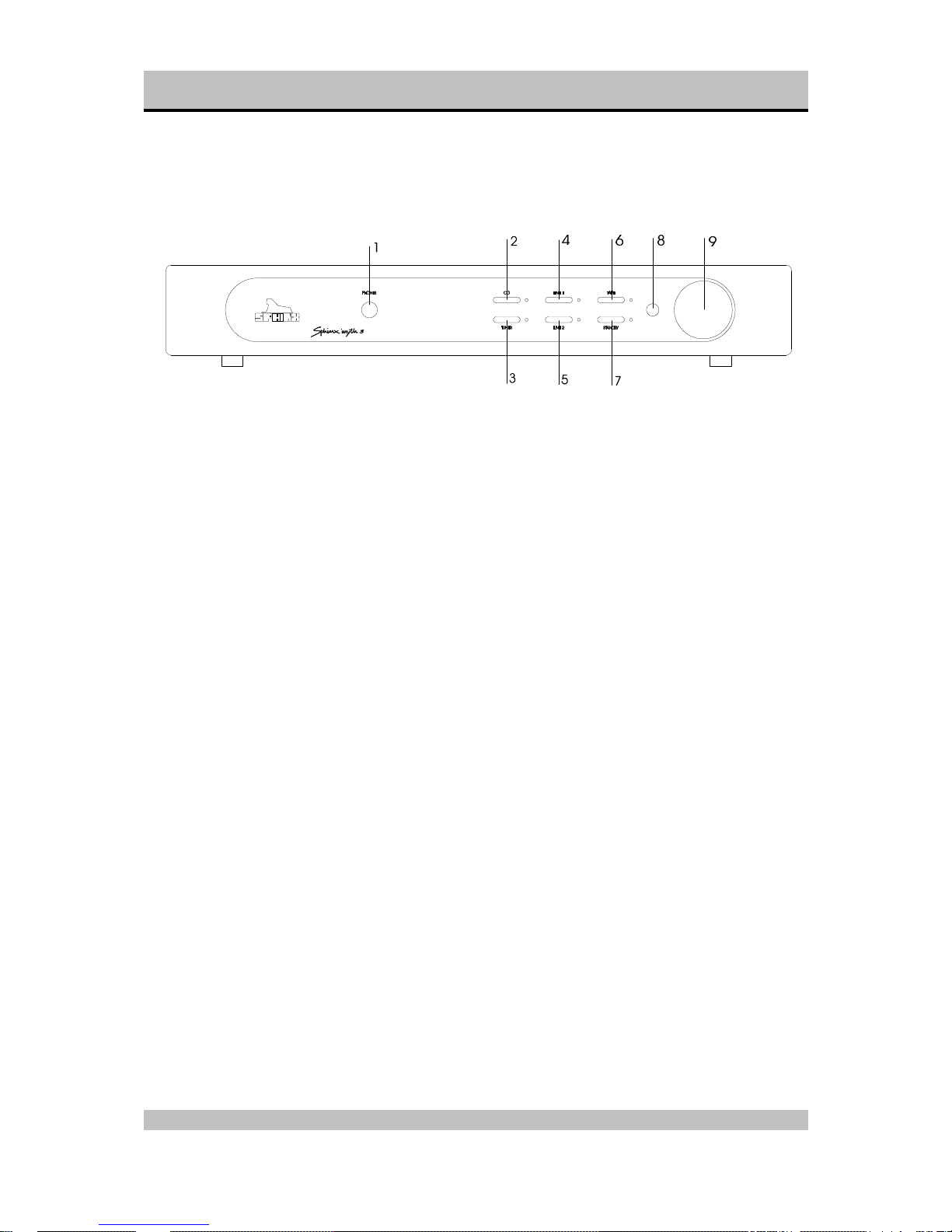
3. THE AMP AT A GLANCE
Front panel
1. PHONES: To connect dynamic stereo
headphones.
2. CD: To select the CD input.
3. TUNER: To select the TUNER input.
4. LINE 1: To select the LINE 1 input.
5. LINE 2: To select the LINE 2 input.
6. TAPE: To select the TAPE IN input.
As soon as you have pressed one of the buttons
2. to 6. the corresponding red LED next to it will
light.
7. STANDBY: To switch the component on and off.
When the component is 'off' (standby) this is
indicated by the red LED.
8. Sensor window for the IR signal from the
Remote Control.
9. VOLUME: With this motor-controlled knob you
may adjust the volume of the loudspeakers.
The volume can be controlled manually or via the
Remote Control.
Page 5

SPHINX Myth 3 Service Manual
5
Rear panel
10. LINE 2: To connect the cinch signal cable from
the signal source for LINE 2.
11. LINE 1: To connect the cinch signal cable from
the signal source for LINE 1.
12. TUNER: To connect the cinch signal cable from
the tuner.
13. CD: To connect the cinch signal cable from the
CD player.
14. TAPE OUT: Connect this output to the Input of
the recorder.
15. TAPE IN: Connect this input to the output of the
recorder.
16. RIGHT OUTPUT: To connect the cable from the
right loudspeaker:
red +
black -
17. LEFT OUTPUT: To connect the cable from the
left loudspeaker:
red +
black -
18. Manufacturer’s label: This shows important
data for the component, such as serial number
and mains power voltage.
19. AC Power: Connect the mains cable to a mains
power outlet (100 - 240 VAC).
20. Fuse holder: Contains a 3.15 A slow type fuse.
21. ON/OFF: This is the mains power switch.
10
11
12
13 14 15 16 17
18
19 21
20
Page 6

SPHINX Myth 3 Service Manual
6
4. OPERATION
Once you have finished connecting all components,
you can switch on the Myth 3.
Connect the mains cable to a mains outlet.
Turn the volume control to 'off' (fully counterclockwise).
Power on
Switch the Myth 3 on with the ON/OFF switch (21)
on the rear panel.
The red LED next to the STANDBY button will blink.
After a few seconds the CD input is selected: the red
LED next to CD (2) will light.
The Myth 3 is now switched on and ready for use.
You can leave the amp on. That way all circuits will
remain at optimum operating temperature and the
audio quality will be 100% immediately after
switching on. Additionally it significantly increases
the life span of the component.
Only if the amp will not be used for a longer period
you might switch it off with the ON/OFF switch (21)
to save energy.
Selecting an input
Select the input with one of the buttons 2. to 6.
As soon as you have selected an input, the red LED
next to the button will light.
CD : To select the CD input.
TUNER : To select the TUNER input.
LINE 1 : To select the LINE 1 input.
LINE 2 : To select the LINE 2 input.
Tape button
Pressing the TAPE button in the front panel (6)
selects the TAPE IN input.
After you press PLAY on the recorder you will hear
the recorded signal.
If you record a tape this button lets you compare the
input signal (as selected with button 2., 3., 4. or 5) to
the signal from the recorder:
IN (LED red) signal from tape
OUT (LED off) signal from selected input
When using a 3-head recorder you can therefore
compare the original signal with the actual recorded
signal (you'll hear the 'off-tape' signal which might be
slightly delayed).
Adjusting the volume
Using the large VOLUME control (9) you can adjust
the sound level from the loudspeakers.
This volume control is motor-controlled. If you adjust
the volume on the Remote Control the knob will turn
automatically. The position of the knob always
correctly indicates the set volume.
Standby button
The STANDBY button (7) temporarily mutes the
sound from the loudspeakers: the red LED will light.
Another press on the button un-mutes the sound, the
LED extinguishes.
You may also use this button when you listen on
headphones and would like to switch the
loudspeakers off. The Mute function has no influence
on the signal to the headphones.
This function can also be controlled using the
Remote Control.
Power off
Switch the Myth 3 temporarily off (to stand-by) with
the STANDBY button (7).
When the Myth 3 will not be used for a longer period,
you may switch it off completely with the ON/OFF
switch (21).
Amplifier switches to Protection Mode...
Indication: the Standby LED blinks rapidly and the
volume control turns automatically to “zero” (fully
counter clockwise).
Note: Switch power off with the ON/OFF switch (21)
and wait for at least 60 seconds. In the mean time,
check all loudspeaker cables for shorted wires! If you
find any, remove the short-circuit to insure fault-free
connection.
Now switch the power on with the ON/OFF switch. If
the amplifier itself is not defective, it will operate
normally again after 30 seconds.
Page 7
SPHINX Myth 3 Service Manual
7
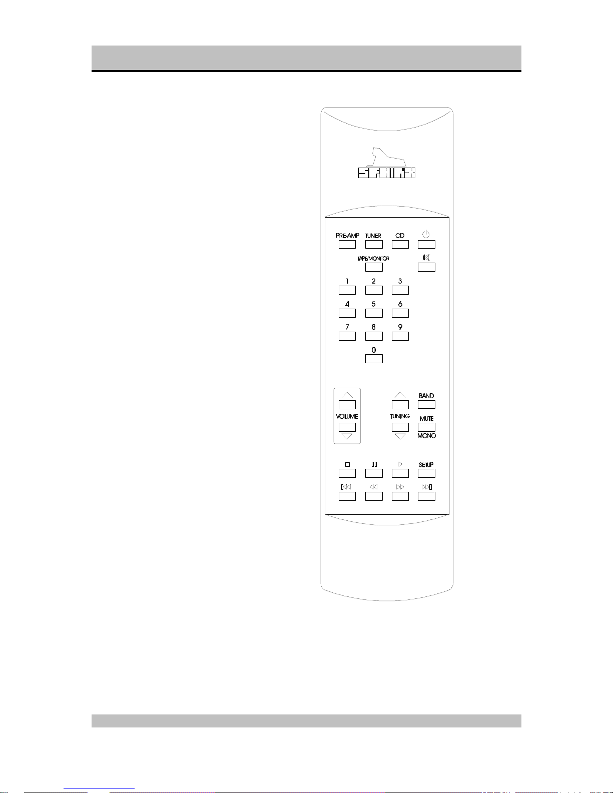
5. SPHINX REMOTE CONTROL
This single Sphinx Remote Control allows you to
control all functions: not only of the Myth 3, but of all
other Sphinx equipment.
Only the following buttons and indications on the
Remote apply to the Myth 3 (the others will not
function):
Buttons
1. PRE-AMP: To select the amp. All buttons
pressed hereafter will control only the amp
functions.
2. STANDBY: Use this red button to switch the
loudspeaker outputs of the Myth 3 off (standby).
3. 1 - 4: To select inputs CD to Line 2 (Note: 5 to 0
do not function):
1 CD
2 Tuner
3 Line 1
4 Line 2
4. TAPE/MONITOR: Use this button to select the
Tape IN input.
5. + button: Pressing this button has the same
effect as rotating the VOLUME control on the
front panel clockwise. You increase the volume.
6. — button: Pressing this button has the same
effect as rotating the VOLUME control on the
front panel anti-clockwise. You decrease the
volume.
Page 8

SPHINX Myth 3 Service Manual
8
Operation
The Sphinx Remote is used with several different
models and can therefore transmit different control
codes, depending on which model has been
selected with the select buttons (1).
Important: Always press the PRE-AMP button before
you send a command (even if you only have one
Sphinx component).
Otherwise it is possible that, although the Remote
will send a signal, nothing happens because the
transmitted signal is not 'recognised' by the
component.
Indoors the Remote may be used up to a distance of
7 meter, provided there is no strong sunlight in the
room and if you aim the Remote at the component.
Always aim the Remote straight at the front panel of
the component, the maximum offset angle is 30°.
Selecting without switching
Suppose, for instance, that you would like to select
the Tuner to Radio 4 without interrupting CD
playback.
In that case you momentarily depress (not longer
than 0.5 sec) the 'TUNER' button and the '4' button.
The same procedure is used for the other system
components.
How to operate the Remote Control with the different
Sphinx components will be explained in the
corresponding User Manual of each component.
Batteries
The four batteries have a life span of approximately
one year during normal use, but shorter when used
more intensely.
Replacement batteries: 1.5 V, model micro or penlite
or LR03 or AAA or AM4 (one of these codes is
indicated on the packaging and the batteries). You
may also use rechargeable 1.5 V batteries.
Note: Position the new batteries exactly as shown in
the illustration at the bottom of the battery
compartment, otherwise the Remote will not
function!
Encountering problems...
Remote Control does not work
Wrong component selected Select the correct one
Distance to component
exceeds 7 m
Use Remote at closer
range
Angle between Remote and
component exceeds ±30°
Decrease angle
Sensor window on front dirty Clean window
Batteries empty or incorrectly
placed
Use new batteries or
replace the old ones
correctly
Strong (sun)light in room Shade off light source
Component is not switched on
(!)
Switch it on
Component reacts differently than expected or
not at all
Wrong component selected Select the correct one
Component or Remote does
not function
Check component with
its original remote
Batteries in Remote empty Use new batteries
Page 9

SPHINX Myth 3 Service Manual
9
6. TECHNICAL SPECIFICATIONS
Bandwidth 10 - 103,000 Hz (+0/-3 dB)
Phase response error <2° (from 0 - 20,000 Hz)
Gain 33 dB max. (44.7 times)
Minimum Power Output (1 - 20.000 Hz)
>2x 50 W into 8 Ω (17.0 dBW), THD <0.01%
>2x 68 W into 4 Ω (18.3 dBW), THD <0.02%
>2x 66 W into 2 Ω (18.2 dBW), THD <0.01%3
Output voltage / current, max. 20 V / 10 A
THD+N (IHF-A) <0.006% (2nd harm., 10-20,000 Hz)
IMD <0.030%
S/N ratio (IHF-A) >100 dB
Channel separation >70 dB (1 - 20,000 Hz)
Slew rate >24 V/µs
Damping factor >525 (1 - 1,000 Hz)
Inputs
cinch, unbalanced 1x Line 2, 1x Line 1, 1x CD, 1x Tuner, 1x Tape
level, nominal 1.25 V
impedance
20 kΩ
Outputs
cinch 1x Tape
headphones 1x 6.3 mm stereo jack, adjustable level
clamp 1x loudspeaker L, 1x loudspeaker R
Supply capacitance 18,800 µF total
Power consumption 550 W max. (57.5 W standby)
Dimensions (h x w x d) 110 x 434 x 330 mm
Weight 7 kg
This unit conforms to the EMC interference regulations issued by the EU and to the CE standards.
This unit complies with safety regulation VDE 0860 and therefore with international safety regulation IEC 65.
Technical specifications may be changed by SPHINX without prior notice if technical developments make this
necessary.
©1999 Audioscript BV
Page 10

SPHINX Myth 3 Service Manual
10
7. ADJUSTMENT PROCEDURES
The Myth 3 is an integrated amplifier, meaning the
pre-amp and power amp sections are combined into
one cabinet.
The Myth 3 only has two parameters for each
channel (so four in total) that might need
adjustment:
- Bias: to set the bias current and bias voltage of
the amplifier for normal use.
- Offset: to set the DC-offset voltage of the
output.
These adjustments might be necessary when the
amplifier has been used for a period of time (and
settings have changed due to ageing) or when a
part of the Myth 3 have been replaced.
Attention:
When re-adjusting any setting please ensure that
there is no loudspeaker connected to the output!
Otherwise the loudspeaker may be seriously
damaged.
Attention:
The amplifier is able to generate high output
voltages of over + or -40 V.
Please be very careful during the adjustments!
Bias
With this procedure you set the proper bias level for
the power FETs. This ensures their Class A
operation at low power levels.
Connect the amplifier according to the drawing
“Measurement Set-up” (page 13).
The input of the amplifier must be shorted (by way
of the MUTE function of the oscillator).
• Switch the amplifier ON and wait until it has
reached the proper working temperature
• Set the millivolt-meter to the DC-range.
• Place the two measuring clips of the meter
across one of the source resistors
Left: R30L, R31L
Right: R30R, R31R
(refer to schematic on page 17/18).
• The level for each should be 8 mV DC (±2 mV).
If not: adjust potmeter P2L (Left) or potmeter
P2R (Right) until the level is 8 mV.
• Repeat this procedure after 20 minutes to
finalise the adjustment.
• Switch the oscillator on and set it to 1 kHz and a
level of 0 dBV (1 V).
• Check the distortion with a THD analyser: it
should be conform to the specified value (0.01%
IHF-A @ 1 – 20 kHz @ 50 W into 8 ohm).
If this is correct the procedure is finished.
• You may now switch off the amplifier or continue
with another adjustment procedure.
Offset
The Offset adjustment procedure minimises the DC
offset value of the amplifier output. This DC offset is
important when capacitive loads are used, such as
electrostatic loudspeakers. These loudspeakers
often use a very low-impedance step-up
transformer. The amplifier ‘sees’ this load as a
short for the DC voltage.
Connect the amplifier according to the drawing
“Measurement Set-up” (page 13).
The input of the amplifier must be shorted (by way
of the MUTE function of the oscillator).
• Switch the amplifier ON and wait until it has
reached the proper working temperature.
• Set the millivolt-meter to the DC-range.
• Place the measurement clips of the meter over
the output terminal.
• The level should not exceed +1 or -1 mV DC.
If it does: adjust potmeter P1L (Left) or P1R
(Right) until the level is within this range.
• Repeat this procedure after 20 minutes to
finalise the adjustment.
• Switch the oscillator on and set it to 1 kHz and a
level of 0 dBV (1 V).
• Check the distortion with a THD analyser: it
should be conform to the specified value (0.01%
IHF-A @ 1 – 20 kHz @ 50 W into 8 ohm).
If this is correct the procedure is finished.
• You may now switch off the amplifier or continue
with another adjustment procedure.
Page 11

SPHINX Myth 3 Service Manual
11
8. PROBLEMS AND SOLUTIONS
At the moment of writing the Myth 3 has no known
specific problems.
If in the future you encounter any problem(s) you
may enter the info in this table. This table can then
be used for future reference.
Please also send (by fax or e-mail) the specific
information to the Sphinx International Service
Department (see page 3): this info can then be
added to the general database to aid others.
Problem Cause Solution Refer to
page…
Bandwidth ≈ 100 kHz
Value of C2L, C2R too large
(220 pF)
Change C2L, C2R value to 47pF17/18
Page 12

SPHINX Myth 3 Service Manual
12
9. DIAGRAMS AND PARTS LISTS
The next pages contain the front and rear panel layout and a complete set of schematic drawings
including the associated parts lists (if applicable).
Page 13

SPHINX Myth 3 Service Manual
13
Measurement Set-up
+
GND
+
GND
Left
Right
B?
MYTH 3
out1 out2
inp2
inp1
gnd
THD
Amplitude
Frequency
Oscillator
THD out
(+) (-) (+) (-)
x
y
inp2
time/div
inp1
gnd
out1 out2
inp2inp1
Scoop
SWITCH-BOX
mVmV
8R
8R
GND
GND
GND
GND
Page 14

SPHINX Myth 3 Service Manual
14
General Overview Myth 3
Myth 3 power supply
M3-ps.sch
Myth 3 keyboard
m3-keyb.sch
Myth 3 control
m3-ctrl.sch
Page 15
SPHINX Myth 3 Service Manual
15
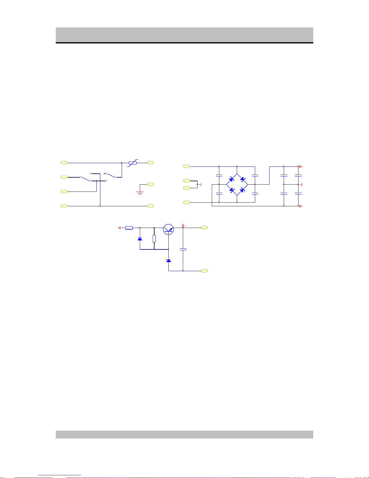
Schematic Diagram Power Supply
ACINP2
EARTH
ACINP1
SW1A
115_230
SW1B
115_230
NTC1
2.5E/8A
C1
220N
C3
220N
C2
220N
C4
220N
D3
SB356
ACS1
ACS4
ACS2
ACS3
+
C5
4700U/50V
+
C6
4700U/50V
+
C7
4700U/50V
+
C8
4700U/50V
GND
GND
+V
-V
Q1
BD679
D2
ZF24V
R2
10K
R1
56R/2W
D1
1N4148
+
C10
10U
+V
+24V
+24VOUT
GNDOUT
Page 16
SPHINX Myth 3 Service Manual
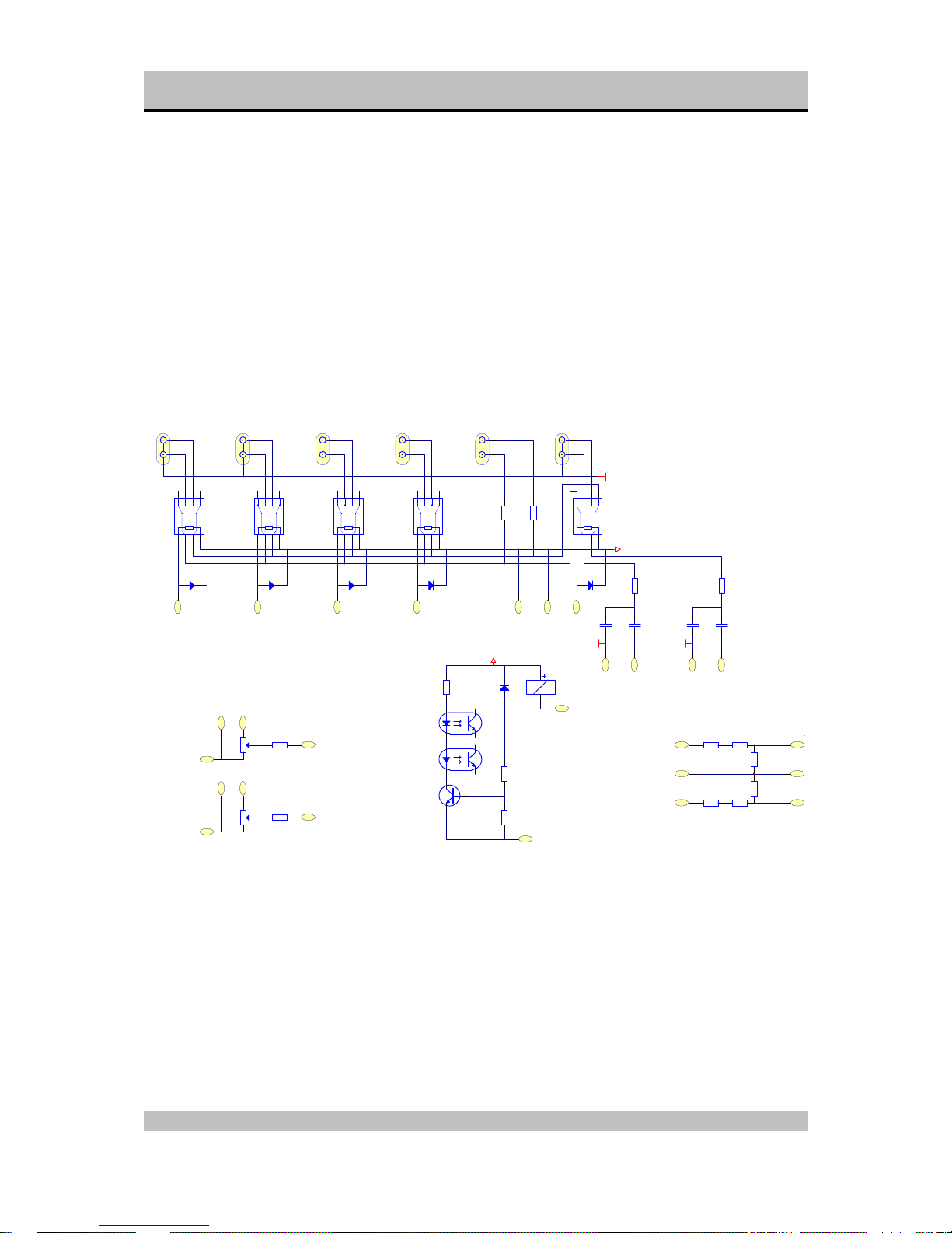
16
Schematic Diagram Input / Output
R53
4k75
R42R
475R
R41R
475R
R41L
475R
R52
4k75
R42L
475R
R51
10k
L2/L1A L2/L1B TUNER/CDA TUER/CDB TAPEA TAPEB
+
REL1
REL16
+
REL2
REL16
+
REL3
REL16
+
REL4
REL16
+
REL5
REL16
LINE2 LINE1 TUNER CD TAPE OUT TAPE IN
D8
1N4148
D9
1N4148
D10
1N4148
D11
1N4148
D12
1N4148
+24V
C21R
10U/100V
C21L
10U/100V
C20R
120P
C20L
120P
AGND AGND
Q17
C2240
D17
1N4148
IC1R
CNY17-D
IC1L
CNY17-D
REL6RLA
RA451024
+24V
AGND
9 10 7 8 643
PM3PM4 PM1PM2
5
2
P1.2
ALPS 20K
P1.1
ALPS 20K
R2
475R
R1
475R
L_O
R_O
R-I
L_ILGI
RGI
LGO
RGO
R11KR2
1K
R3
1K
R6
1K
R5
1K
R4
1K
ORANJE
RIGHT
GROEN
LEFT
RIGHT PHONES
GND PHONES
LEFT PHONES
GEEL
GND
Page 17

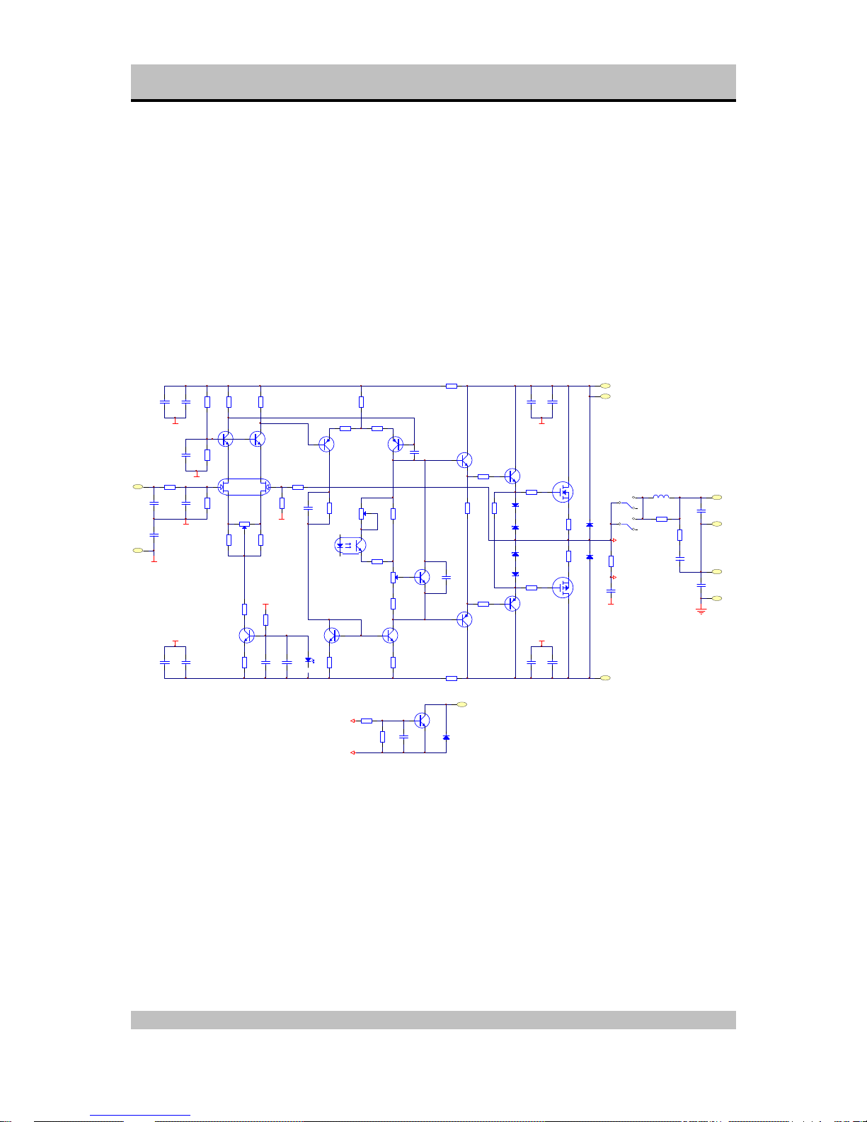
SPHINX Myth 3 Service Manual
17
Schematic Diagram Amplifier Left
Q1L
K389
Q2L
C1775 Q3L
C1775
R7L
820R
R8L
820R
R9L
22R
R10L
22R
R11L
1K00
R13L
22K
R12L
475R
R2L
22K0
R1L
475R
R5L
22K
R6L
120K
AGND
AGND
P1L
200R
Q4L
C1775
AGND
C1AL
120P
C1BL
120P
C2L
220P
C3L
1U
C12L
100N
C14L
100N
C9L
100N
C6L
100N
C15L
100N
C17L
100N
+
C11L
220U/63V
+
C13L
220U/63V
+
C10L
100U/16V
+
C18L
10U/100V
+
C16L
10U/100V
C5L
10P
C4L
100N
D1L
LED
Q5L
A970
Q6L
A970
R15L
39R
R17L
39R
R16L
56R0
R14L
18K0
R4L
22K
R3L
475R
R19L
220R
R24L
1KR18L
3K3
R26L
22R
R20L
300R
R21L
300R
R25L
22R
Q8L
C2240
Q7L
C2240
P2L
500R
AGND
AGND
AGND
AGND
AGND
AGND
Q9L
C2240
P3L
50k
R41L
50k
Q11L
A1145
Q10L
C2705
Q12L
C4382
Q13L
A1668
D3L
ZF10
D2L
ZF10
D4L
ZF10
D5L
ZF10
R27L
47R/2W
R28L
100R
R29L
100R
R30L
0R22
R31L
0R22 R32L
47R/2W
R34L
10R/5W
R33L
10R/5W
R22L
2R2
R23L
2R2
Q15L
A1668
Q14L
K1058
D6L
1N4007
D7L
1N4007
C7L
47N
AGND
A
B
IC1L
CNY17-D
REL6LB
RELAIS DPDT
REL6LC
RELAIS DPDT
L1L
EE-K-021
C8L
330N
C21L
10N
C20L
1N
V+
V+_BEV
V-
OUT+
OUT-
PM7
PM8
GNDOUT
KAST
R35L
220R
R36L
100R
C19L
100N
Q16L
C1775
D2L
1N4148
A
B
OC
Page 18
SPHINX Myth 3 Service Manual
18
Schematic Diagram Amplifier Right
Q1R
K389
Q2R
C1775 Q3R
C1775
R7R
820R
R8R
820R
R9R
22R
R10R
22R
R11R
1K00
R13R
22K
R12R
475R
R2R
22K0
R1R
475R
R5R
22K
R6R
120K
AGND
AGND
P1R
200R
Q4R
C1775
AGND
C1AR
120P
C1BR
120P
C2R
220P
C3R
1U
C12R
100N
C14R
100N
C9R
100N
C6R
100N
C15R
100N
C17R
100N
+
C11R
+
C13R
220U/63V
+
C10R
100U/16V
+
C18R
10U/100V
+
C16R
C5R
10P
C4R
100N
D1R
LED
Q5R
A970
Q6R
A970
R15R
39R
R17R
39R
R16R
56R0
R14R
18K0
R4R
22K
R3R
475R
R19R
220R
R24R
1KR18R
3K3
R26R
22R
R20R
300R
R21R
300R
R25R
22R
Q8R
C2240
Q7R
C2240
P2R
500R
AGND
AGND
AGND
AGND
AGND
AGND
Q9R
C2240
P3R
50k
R41R
50k
Q11R
A1145
Q10R
C2705
Q12R
C4382
Q13R
A1668
D3R
ZF10
D2R
ZF10
D4R
ZF10
D5R
ZF10
R27R
47R/2W
R28R
100R
R29R
100R
R30R
0R22
R31R
0R22 R32R
47R/2W
R34R
10R/5W
R33R
10R/5W
R22R
2R2
R23R
2R2
Q15R
A1668
Q14R
K1058
D6R
1N4007
D7R
1N4007
C7R
47N
AGND
A
B
IC1R
CNY17-D
REL6RB
RELAIS DPDT
REL6RC
RELAIS DPDT
L1R
EE-K-021
C8R
330N
C21R
10N
C20R
1N
V+
V+_BEV
V-
R35R
220R
R36R
100R
C19R
100N
Q16R
C1775
D2R
1N4148
A
B
OC
Page 19

SPHINX Myth 3 Service Manual
19
Schematic Diagram keyboard
S1A S1B S2A S2B S3A S3B S4A S4B S5A S5B S6A S6B
R1
3K3
R2
3K3
D1
LED
D2
LED
D3
LEDD4LED
D5
LED
D6
LED
R3
3K3
TAPE-M
LINE1
LINE2
CD
TUNER
MUTE
+24V
L+24V
L-TAPE
L-L2
L-TUNER
L-MUTE
L-CD
L-L1
S-L2 S-CD S-TUNER S-TAPES-MUTES-L1
Page 20

SPHINX Myth 3 Service Manual
20
Schematic Diagram control
C1
100ND21N4148D11N4148
R5
4K7
R8
4K7
R6
4K7
R7
4K7
R3
10K
R13
10K
R4
10KQ11
BC807
Q7
BC817Q9BC817
+
C10
330U/6V
Q8
BC817
Q10
BC807
C9
100N
C4
100N
+
C13
10U/100V
C7
100N
VoutVin
GND
U1 7805
C3
100N
Q2
A970Q3A970
Q4
C2240Q5C2240
M1 M2
C5
100N
C6
100N
Q1
8MHz
R16
4K7
R17
4K7
R18
33K
R14
10K
R11
390R
R12
390R
V+
2
D
1
GND
3
IR
IR1
SFH506-38
+
C8
1U5
+
C27
68U/6V3
C14
100N
OVER_CR
OVER_CL
DGND
+5V
VCC
/MR
GND
PFI /PFO
WDI
/RES
/WDO
IC1
ADM705
R12
4K7
R11
4K7
Q13
BC807
+5V
+5V
DGND
PROTECT
DGND
X1
11
X2
10
P17-T020P37
21
P36
22
P35
23
P34
1
P14
17
P15-INT0
18
P33
2
P11
14
P32
3
P31
4
P30
5
P16-INT1
19
VCC
24
P13
16
P12
15
P10
13
GND
12
P02
6
P01-SDA
7
P00-SCL
8
RES
9
MCT1
83751
IN1
1
IN2
2
IN3
3
O1
18
O2
17
O3
16
O4
15
IN6
6
IN55O5
14
IN7
7
13
10
O7
12
GND
9
IN4
4
IN88O8
11
C
10
U2
ULN2803
4K7
4K7
4K7
4K7
4K7
4K7
4K7
1
RN1A
4K7
+
C36
22U/16V
DGND
R2 4K7
Q2
BC807
R1
4K7
DGND
DGND
FL-TAPE
FL-L1
FL-L2
FL-TUNER
FL-CD
MUTE_LED
FL-REL
123456789
10
DGND
FL-ERROR
+24VS
C23
100N
C19
100N
C24
100N
C26
100N
C20
100N
C21
100N
C22
100N
C25
100N
4K7
4K7
4K7
4K7
4K7
4K7
4K7
1
RN1A
4K7
+5V
+5V
C33
100N
C32
100N
C31
100N
C30
100N
C29
100N
C28
100N
DGND
DGND
C6
100N
+5V
PROTECT
C5
100N
+5V
DGND
DGND
D3
24V
D4
5V6D51N4148
R15
4K7
Q12
BC817
+
C34
1U/35V
+24VS
+24V
DGND
Q14
BCV46
+24V
DGND
FL-ERROR
+40V
C2
100N
C11
100N
C12
100N
C14
100N
C15
100N
C16
100N
DGND
KAST +5V
S-GND
S-TAPE
S-L2
S-CD
S-TUNER
S-L1
S-MUTE
L+24V
L-MUTE
L-CD
L-TUNER
L-L1
L-L2
L-TAPE
Page 21

SPHINX Myth 3 Service Manual
21
Parts List
Designator Part Type Description
+24VOUT 1PIN Connector
ACINP1 1PIN Connector
ACINP2 1PIN Connector
ACP1 1PIN Connector
ACP2 1PIN Connector
ACP3 1PIN Connector
ACP4 1PIN Connector
ACS1 1PIN Connector
ACS2 1PIN Connector
ACS3 1PIN Connector
ACS4 1PIN Connector
C1 100N MKT capacitor
C1 220N MKT capacitor
C10 10U Electrolitic capacitor
C10 330U/6V Electrolitic capacitor
C10L 100U/16V Electrolitic capacitor
C10R 100U/16V Electrolitic capacitor
C11 100N MKT capacitor
C11L 220U/63V Electrolitic capacitor
C11R 220U/63V Electrolitic capacitor
C12 100N MKT capacitor
C12L 100N MKT capacitor
C12R 100N MKT capacitor
C13 10U/100V Electrolitic capacitor
C13L 220U/63V Electrolitic capacitor
C13R 220U/63V Electrolitic capacitor
C14 100N MKT capacitor
C14 100N MKT capacitor
C14L 100N MKT capacitor
C14R 100N MKT capacitor
C15 100N MKT capacitor
C15L 100N MKT capacitor
C15R 100N MKT capacitor
C16 100N MKT capacitor
C16L 10U/100V Electrolitic capacitor
C16R 10U/100V Electrolitic capacitor
C17L 100N MKT capacitor
C17R 100N MKT capacitor
C18L 10U/100V Electrolitic capacitor
C18R 10U/100V Electrolitic capacitor
C19 100N MKT capacitor
C19L 100N MKT capacitor
C19R 100N MKT capacitor
C1AL 120P MKT capacitor
C1AR 120P MKT capacitor
C1BL 120P MKT capacitor
C1BR 120P MKT capacitor
C2 100N MKT capacitor
Page 22

SPHINX Myth 3 Service Manual
22
Designator Part Type Description
C2 220N MKT capacitor
C20 100N MKT capacitor
C20L 120P MKT capacitor
C20L 1N MKT capacitor
C20R 120P MKT capacitor
C20R 1N MKT capacitor
C21 100N MKT capacitor
C21L 10N MKT capacitor
C21L 10U/100V MKT capacitor
C21R 10N MKT capacitor
C21R 10U/100V MKT capacitor
C22 100N MKT capacitor
C23 100N MKT capacitor
C24 100N MKT capacitor
C25 100N MKT capacitor
C26 100N MKT capacitor
C27 68U/6V3 Electrolitic capacitor
C28 100N MKT capacitor
C29 100N MKT capacitor
C2L 220P MKT capacitor
C2R 220P MKT capacitor
C3 100N MKT capacitor
C3 220N MKT capacitor
C30 100N MKT capacitor
C31 100N MKT capacitor
C32 100N MKT capacitor
C33 100N MKT capacitor
C34 1U/35V Electrolitic capacitor
C36 22U/16V Electrolitic capacitor
C3L 1U MKT capacitor
C3R 1U MKT capacitor
C4 100N MKT capacitor
C4 220N MKT capacitor
C4L 100N MKT capacitor
C4R 100N MKT capacitor
C5 100N MKT capacitor
C5 100N MKT capacitor
C5 4700U/50V Electrolitic capacitor
C5L 10P MKT capacitor
C5R 10P MKT capacitor
C6 100N MKT capacitor
C6 100N MKT capacitor
C6 4700U/50V Electrolitic capacitor
C6L 100N MKT capacitor
C6R 100N MKT capacitor
C7 100N MKT capacitor
C7 4700U/50V Electrolitic capacitor
C7L 47N MKT capacitor
C7R 47N MKT capacitor
Page 23

SPHINX Myth 3 Service Manual
23
Designator Part Type Description
C8 1U5 Electrolitic capacitor
C8 4700U/50V Electrolitic capacitor
C8L 330N MKT capacitor
C8R 330N MKT capacitor
C9 100N MKT capacitor
C9L 100N MKT capacitor
C9R 100N MKT capacitor
D1 1N4148 Diode
D1 1N4148 Diode
D1 LED LED
D10 1N4148 Diode
D11 1N4148 Diode
D12 1N4148 Diode
D17 1N4148 Diode
D1L LED LED
D1R LED LED
D2 1N4148 Diode
D2 LED LED
D2 ZF24V Zener diode
D2L 1N4148 Diode
D2L ZF10 Zener diode
D2R 1N4148 Diode
D2R ZF10 Zener diode
D3 24V Zener diode
D3 LED LED
D3 SB356 Diode
D3L ZF10 Zener diode
D3R ZF10 Zener diode
D4 5V6 Zener diode
D4 LED led
D4L ZF10 Zener diode
D4R ZF10 Zener diode
D5 1N4148 Diode
D5 LED LED
D5L ZF10 Zener diode
D5R ZF10 Zener diode
D6 LED LED
D6L 1N4007 Diode
D6R 1N4007 Diode
D7L 1N4007 Diode
D7R 1N4007 Diode
D8 1N4148 Diode
D9 1N4148 Diode
EARTH 1PIN Connector
GEEL GND Connector
GNDOUT 1PIN Connector
GROEN LEFT Connector
IC1 ADM705 IC
IC1L CNY17-D Optocoupler
Page 24

SPHINX Myth 3 Service Manual
24
Designator Part Type Description
IC1L CNY17-D Optocoupler
IC1R CNY17-D Optocoupler
IC1R CNY17-D Optocoupler
IR1 SFH506-38 Infrared receiver
L1L EE-K-021 Coil
L1R EE-K-021 Coil
L2/L1 CINCH-MYTH4P Connector
M1 1PIN Connector
M2 1PIN Connector
MCT1 83751
NTC1 2.5E/8A NTC myth devices
ORANJE RIGHT Connector
P1.1 ALPS 20K Adj. Potmeter
P1.2 ALPS 20K Adj. Potmeter
P1L 200R Adj. Potmeter
P1R 200R Adj. Potmeter
P2L 500R Adj. Potmeter
P2R 500R Adj. Potmeter
P3L 50k Adj. Potmeter
P3R 50k Adj. Potmeter
Q1 8MHz XTAL
Q1 BD679 Transistor
Q10 BC807 Transistor
Q10L C2705 Transistor
Q10R C2705 Transistor
Q11 BC807 Transistor
Q11L A1145 Transistor
Q11R A1145 Transistor
Q12 BC817 Transistor
Q12L C4382 Transistor
Q12R C4382 Transistor
Q13 BC807 Transistor
Q13L A1668 Transistor
Q13R A1668 Transistor
Q14 BCV46 Transistor
Q14L K1058 Transistor
Q14R K1058 Transistor
Q15L A1668 Transistor
Q15R A1668 Transistor
Q16L C1775 Transistor
Q16R C1775 Transistor
Q17 C2240 Transistor
Q1L K389 Dual N-JFET
Q1R K389 Dual N-JFET
Q2 A970 Transistor
Q2 BC807 Transistor
Q2L C1775 Transistor
Q2R C1775 Transistor
Q3 A970 Transistor
Page 25

SPHINX Myth 3 Service Manual
25
Designator Part Type Description
Q3L C1775 Transistor
Q3R C1775 Transistor
Q4 C2240 Transistor
Q4L C1775 Transistor
Q4R C1775 Transistor
Q5 C2240 Transistor
Q5L A970 Transistor
Q5R A970 Transistor
Q6L A970 Transistor
Q6R A970 Transistor
Q7 BC817 Transistor
Q7L C2240 Transistor
Q7R C2240 Transistor
Q8 BC817 Transistor
Q8L C2240 Transistor
Q8R C2240 Transistor
Q9 BC817 Transistor
Q9L C2240 Transistor
Q9R C2240 Transistor
R1 1K Resistor
R1 3K3 Resistor
R1 475R Resistor
R1 4K7 Resistor
R1 56R/2W Resistor
R10L 22R Resistor
R10R 22R Resistor
R11 390R Resistor
R11 4K7 Resistor
R11L 1K00 Resistor
R11R 1K00 Resistor
R12 390R Resistor
R12 4K7 Resistor
R12L 475R Resistor
R12R 475R Resistor
R13 10K Resistor
R13L 22K Resistor
R13R 22K Resistor
R14 10K Resistor
R14L 18K0 Resistor
R14R 18K0 Resistor
R15 4K7 Resistor
R15L 39R Resistor
R15R 39R Resistor
R16 4K7 Resistor
R16L 56R0 Resistor
R16R 56R0 Resistor
R17 4K7 Resistor
R17L 39R Resistor
R17R 39R Resistor
Page 26

SPHINX Myth 3 Service Manual
26
Designator Part Type Description
R18 33K Resistor
R18L 3K3 Resistor
R18R 3K3 Resistor
R19L 220R Resistor
R19R 220R Resistor
R1L 475R Resistor
R1R 475R Resistor
R2 10K Resistor
R2 1K Resistor
R2 3K3 Resistor
R2 475R Resistor
R2 4K7 Resistor
R20L 300R Resistor
R20R 300R Resistor
R21L 300R Resistor
R21R 300R Resistor
R22L 2R2 Resistor
R22R 2R2 Resistor
R23L 2R2 Resistor
R23R 2R2 Resistor
R24L 1K Resistor
R24R 1K Resistor
R25L 22R Resistor
R25R 22R Resistor
R26L 22R Resistor
R26R 22R Resistor
R27L 47R/2W Resistor
R27R 47R/2W Resistor
R28L 100R Resistor
R28R 100R Resistor
R29L 100R Resistor
R29R 100R Resistor
R2L 22K0 Resistor
R2R 22K0 Resistor
R3 10K Resistor
R3 1K Resistor
R3 3K3 Resistor
R30L 0R22 Resistor
R30R 0R22 Resistor
R31L 0R22 Resistor
R31R 0R22 Resistor
R32L 47R/2W Resistor
R32R 47R/2W Resistor
R33L 10R/5W Resistor
R33R 10R/5W Resistor
R34L 10R/5W Resistor
R34R 10R/5W Resistor
R35L 220R Resistor
R35R 220R Resistor
Page 27

SPHINX Myth 3 Service Manual
27
Designator Part Type Description
R36L 100R Resistor
R36R 100R Resistor
R3L 475R Resistor
R3R 475R Resistor
R4 10K Resistor
R4 1K Resistor
R41L 475R Resistor
R41L 50k Resistor
R41R 475R Resistor
R41R 50k Resistor
R42L 475R Resistor
R42R 475R Resistor
R4L 22K Resistor
R4R 22K Resistor
R5 1K Resistor
R5 4K7 Resistor
R51 10k Resistor
R52 4k75 Resistor
R53 4k75 Resistor
R5L 22K Resistor
R5R 22K Resistor
R6 1K Resistor
R6 4K7 Resistor
R6L 120K Resistor
R6R 120K Resistor
R7 4K7 Resistor
R7L 820R Resistor
R7R 820R Resistor
R8 4K7 Resistor
R8L 820R Resistor
R8R 820R Resistor
R9L 22R Resistor
R9R 22R Resistor
REL1 REL16 Relay
REL2 REL16 Relay
REL3 REL16 Relay
REL4 REL16 Relay
REL5 REL16 Relay
REL6RL RA451024 Relay
RN1 4K7 R-ARRAY
RN1 4K7 R-ARRAY
S1 SWITCH-DPST SWITCH-DPST
S2 SWITCH-DPST SWITCH-DPST
S3 SWITCH-DPST SWITCH-DPST
S4 SWITCH-DPST SWITCH-DPST
S5 SWITCH-DPST SWITCH-DPST
S6 SWITCH-DPST SWITCH-DPST
SW1 115_230 SWITCH SPDT X 2
TAPE CINCH-MYTH4P Connector
Page 28

SPHINX Myth 3 Service Manual
28
Designator Part Type Description
TUNER/CD CINCH-MYTH4P Connector
U1 7805 IC
U2 ULN2803 ULN2803
 Loading...