

Spheros Thermo S 160, Thermo S 230, Thermo S 400, Thermo S 300, Thermo S 350 Workshop Manual

Water Heater
Workshop Manual
Thermo S 160
Thermo S 230
Thermo S 300
Thermo S 350
Thermo S 400
with Control Unit 1586
Status: 01/2012
Ident.-no. 11114913B


1 Introduction
1.1 Content and purpose 101
noitiddA4.1
hev yawliar rof snoitaluger noitallatsnI2.5.1
tpadA4.5.1
2 Technical data
2.1 Electrical components 201
2.2 F
uel 201
3 Assemblies and components descriptions
3.1 Burner 302
3.1.1 Combustion air fan 302
3.1.2 Fuel pump 302
3.1.4 Control unit 303
3.1.6 Temperature sensors with water temperature sensor and integrated overheating protection 304
3.2 Heat exchanger 305
3.3 Combustion chamber 306
3.4 Circulating pump 307
3.4.1 Aquavent 5000 (U4814) and Aquavent
3.4.2 Aquavent 6000C (U4855) and Aquavent 6000SC (U4856) circulating pumps 308
3.5 Fuel lter 308
5000S (U4854) circulating pumps 307
noitcudortnI1004/053/003/032/061 SomrehT
101 ytidilav launam pohskroW2.1
101 tnetnoc dethgilhgih fo gninaeM3.1
101 noitatnemucod elbacilppa la
101 snoitaluger ytefas dna noitallatsnI5.1
101 snoitaluger noitallatsni lageL1.5.1
201 selci
201 snoitaluger ytefas lareneG3.5.1
401 ssenrah gniriw re
501 egnahc dna tnemevorpmI rof snoitsegguS6.1
303 retaeherp kcolb elzzoN3 .1.3
403 sedortcele noitingi htiw tinu noitingi cinortcelE5.1.3
4 Heater functions
4.2.1 Switching on and start 402
4.2.2 Heating operation 402
4..3 Switching o 403
4.3 Diagnosis interfac 404 sisongaid-
4.3.1 Test plug 405
4.5 Malfunction interlock 406
4.5.1 Malfunctions during switch 406 e rudecorp trats dna no-gni
5.4
4.6 Heater interlock 407
4.7 Error output 408
TTS dna e
epo retaeh gnirud snoitcnuflaM2.5.4
er kcolretni noitcnuflaM4.
5 Troubleshooting and error correction
5.1 General 501
104 noitpircsed ytilanoitcnuf retaeh lareneG1.4
204 ecneuqes retaeh lanoitarepO2.4
604 kcolretni retaeh dna kcolretni noitcnuflaM4.4
604 noitar
704 nwod-nur gnirud snoitcnuflaM3.5.4
704 ecnaraelc rorre dna esael
704 esaeler kcolretni retaeH1.6.4
1

1 Introduction Thermo S 160/230/300/350/400
5.2 General error symptoms 501
5.3 Malfunction code output via flash code 503
5.4 Error symptoms during functional tests with malfunction code output or diagnosis 505
5.4.1 Error symptom "No start within safety period" 505
5.4.2 Error symptom "Flame interruption" 505
5.4.3 Error symptom "Low voltage" 507
5.4.4 Error symptom "Extraneous light detected prior to ignition or during run-down" 508
5.4.5 Error symptom "Flame detector defective" 509
5.4.6 Error symptoms "Temperature sensor / overheating protection defective" and "Overheating" 509
5.4.7 Error symptom "Circulating pump interruption" 509
5.5 Individual component tests 510
5.5.1 General visual inspection 510
5.5.2 Heat exchanger visual inspection 510
5.5.3 Combustion chamber visual inspection 510
5.5.4 Resistance check of the temperature sensor with integrated overheating protection 511
5.5.5 Adapter wiring harness inspection 512
5.5.6 Fan and combustion air intake line visual inspection 512
5.5.7 Burner motor inspection 512
5.5.8 Electronic ignition unit inspection 513
5.5.9 Ignition electrode inspection 514
5.5.10 Flame detector inspection 515
5.5.11 Fuel pump inspection 516
5.5.12 Solenoid valve inspection 517
5.5.13 Nozzle block preheater inspection 518
5.5.14 Circulating pump inspection 519
6 Schematic diagrams
6.1 General 601
7 Servicing
7.1 General 701
7.1.1 Heater servicing 701
7.2 Servicing 701
7.2.1 CO2 content adjustment 702
8 Burner, components and heater removal and installation
8.1 General 801
8.2 Burner removal and installation 802
8.3 Removal and installation of the temperature sensor with integrated overheating protection 803
8.4 Hood removal and installation 803
8.5 Combustion air fan removal and installation 804
8.6 Electronic ignition unit and ignition electrode removal and installation 806
8.7 Control unit removal and installation 808
8.8 Fuel pump removal and installation 808
8.9 Solenoid valve removal and installation 810
8.10 Atomiser nozzle removal and installation 810
8.11 Combustion chamber removal and installation 811
8.12 Heat exchanger removal and installation 811
8.13 Heater removal and installation 811
8.14 Start-up after burner or heater installation 812
8.14.1 Bleeding of the fuel system 812
8.14.2 Bleeding of the water circulation 812
2

Thermo S 160/230/300/350/400 1 Introduction
9 Modifications and retrofits
10 Packing / storage
and shipping
10.1 General 1001
Appendix A 1
Periodic heater maintenance A-2
3

1 Introduction Thermo S 160/230/300/350/400
4

noitcudortnI1004/053/003/032/061 SomrehT
1 Introduction
1.1 Content and purpose
This workshop manual is used to support personnel
briefed and/or trained by Spheros during
maintenance and repair of water heaters Thermo
S160, S230, S300, S350 and S400.
1.2 Workshop manual validity
The workshop manual applies to heaters listed on the title
page of this document.
It may be subjected to modifications and amendments.
The respectively currently val
This version can be found on the Spheros homepage
under Service / Technical Documents.
1.3 Meaning of highlighted content
WARNINGS, CAUTIONS, and NOTES in this manual have
the following meaning:
This heading is used to highlight that non-compliance
with instructions or procedures may cause injuries or
lethal accidents to personnal.
This heading is used to highlight that non-compliance
with instructions or procedures may cause damage
to equipment.
id version is binding.
WARNING
CAUTION
1.5 Installation and safety regulations
1.5.1 Legal installation regulations
For the heaters exist type appr ovals according to the ECE
Regulations
R10 (EMC): No. 03 5266 and
R122 (Heater) No. 00 0208 for Thermo S 160
No. 00 0226 for Thermo S 230
No. 00 0227 for Thermo S 300
No. 00 0228 for Thermo S 350
No. 00 0225 for Thermo S 400
Installation is governed abov
Annex 7 of the
The provisions of these Regulations are binding within
the
territory governed by ECE Regulations and should
similarly be observed in
regulations.
(Extract from ECE Regulation R122, Annex 7)
4. The heater must have a manufacturer’s label showing
the manufacturer’s name, the model number and type
together with its rat
must also be stated and, where relevant, the operating
voltage and gas pressure.
7.1. A clearly visible tell-tale in the operaqtor’s field of view
shall inform when the combustion heater is switched on or
off.
(Extract from ECE Regulation R122, Part I)
ECE Regulation R122.
ed output in kilowatts. The fuel type
e all by the provisions in
NOTE
1.5.2 Installation regulations for railway
vehicles
NOTE
This heading is used to highlight and draw specific
attention to information.
1.4 Additional applicable documentation
We recommend the use of additional documentation.
References are provided in the workshop manual at
appropriate locatio
The following documents can be consulted during
operation and maintenance of the heaters listed on the
title page:
t Operating instruction
t Installation instruction
t Technical communications
t Technical information
t Spare parts list
ns.
For heater models Thermo S 230 / 300 / 350 / 400 Rail a
design certification acc. to § 33 EBO (= Federal Railway
Authority) has been issued with the following approval
number: EBA 32AZ3/0006/10.
Particular attention must be given to incidental provision
1.6 of the design certification:
Should the manufacturer, operator or service technician
gain knowledge of any accidents and damage (caused by
fire, explosion, escape of Diesel fuel or heating oil EL) that
may have occurred despite proper use of the heater, he is
required to immediately notify the certifying body thereof.
1.5.3 General safety regulations
General accident prevention regulations must be
observed.
"General safety regulations" beyond the scope of these
regulations are listed below.
101

SomrehTnoitcudortnI1 160/230/300/350/400
The safety regulations must be observed during
operation, maintenance and repair of heaters of the
Thermo S series.
For heaters in vehicles, which are not subjected to the
European Directive, inspection and approval by the
respective inspection authority is required, if applicable
regulations are in place.
The year of first start-up must be permanently marked
on the type plate by removal of not applicable dates.
The heaters are registered and licensed for the use in
vehicles according to the respective EU Directive 70/156/
.g. 2001/56/EC). When using the heater for other
ECC (e
applications not subjected to this EU Directive (e.g. ships),
respective applicable r egulations must be fulfilled.
CAUTION
The heaters are not approved for vehicles subjected to
Directive 94/55/EC (ADR).
The heater may only be installed in the driver's cab or
passenger compartment, if an installation box is used,
which can be tightly sealed vs. the vehicle interior. The
installation box must be sufficiently vented from the
outside.
If the temperature within the installation box exceeds the
permissible ambient temperature of the heater, the
venting opening must be increased after consultation with
Spheros.
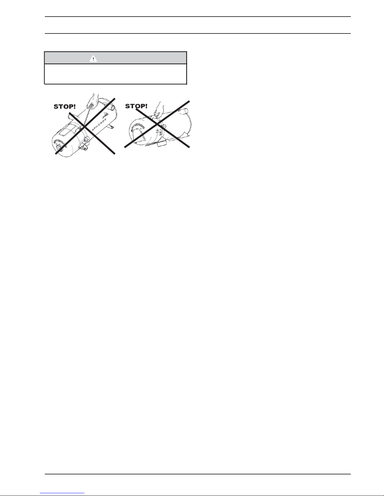
WARNING
For risk of poisoning and suffocation the heater may
not be used in closed rooms such as garages or
workshops without exhaust fume extraction. This
also applies when pre-set times/timers are used. This
also applies for burner operation during adjustment
of the CO content in the exhasut dumes.
For explosion risk the heater must be switched off at
gas stations and gas systems.
For explosion risk the heater must be switched off,
when combustible fumes or dust can be generated
(e.g. in the proximity of fuel, coal, wood dust, grain
storage/silos
2
or similar).
CAUTION
The heaters may only be installed in horizontal
position.
WARNING
If operated without coolant (overheating!), the heaters
outer enclosure may reach the ignition temperature of
diesel fuel during operation!
Dripping or evaporating fuel should not accumulate
or ignite on hot parts or electrical equipment.
The heater should be installed as low as possible to
ensure automatic venting of heater and circulating
pump. This in particular applies for the circulating
pump, which does not automatically draw.
CAUTION
Prior to opening the heater it must be disconnected
from the vehicle electrical system.
NOTE
The heater should always be disconnected from the
vehicle electrical system prior to disconnecting the
temperature sensor plug.
If the order is reversed, t he heater will automatically
be interlocked.
Prior to removing the burner from the heat exchanger,
the temperature sensor plug must be removed.
CAUTION
A temperature of 110°C may not be exceed
heater areas (storage temperature).
Exceeding the temperature may cause heater
malfunctions and permanent damage to the
electronics.
Electrical cables must be routed avoiding isolation
damage (e.g. by pinching, heat development,
bending, fraying, etc.).
ed in the
After coolant replacement sufficient purging of the
cooling system must be ensured. Insufficient venting
heating operation can cause malfunctions due to
overheating.
Proper venting can be recognised by almost noise-free
operation of the circula
The opening pressure in the vehicle cooling system,
usually indicated on the cooler lid, may not exceed 2.0 bar
working overpressure (also applies to separate heating
circulations).
Hose connections must be secured with hose clamps
against slipping.
ting pump.
CAUTION
The tightening torques of the used hose clamps must
be observed.
102
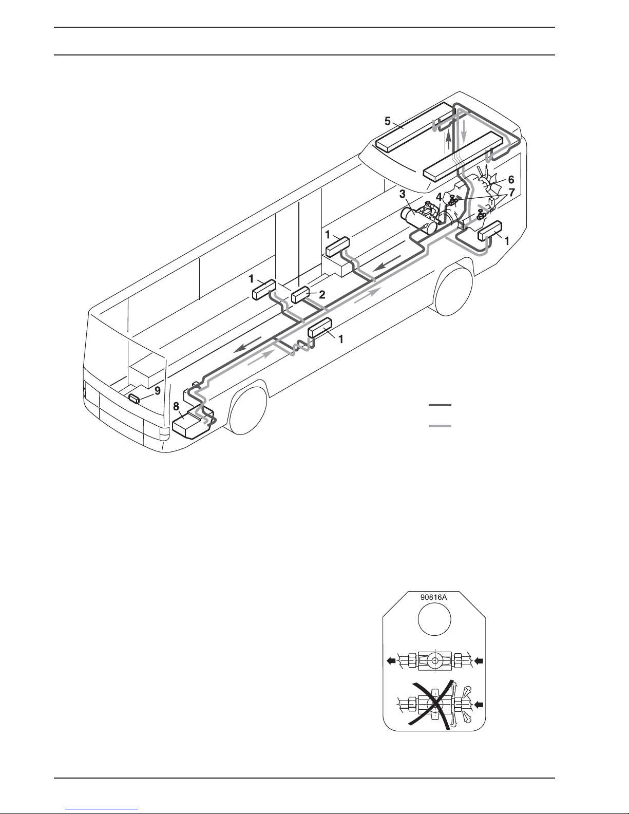
Water heating circulation system - wall heater and roof channel heater
1 Wall heater with fan
2 Heat exchanger at the entrance
3 Heater
4 Circulation pump
5 Roof heat exchanger
6 Vehicle engine
7 Shut-o valve
8 Driver seat heater
9 Control element
SomrehTnoitcudortnI1 160/230/300/350/400
Fig. 101 Heater installation example in a bus
Coolant level verification and cooling system purging
must be performed acco rding to the vehicle
manufacturer's specifications. The coolant in the heating
circulation system should contain at least 20 % of an antifreezing agent recommended by the vehicle
manufacturer.
The anti-freezing agent content should not exceed 60 %.
Fuel hoses may not be bent or twisted during installation.
In order to avoid sagging, they should secured using
clamps in 10 inch (25 cm) distances.
Fuel lines must be protected against temperature
exposure.
Permissible fuel line dimensions must be o
btained from
the installation instruction.
Supply
Return
If a shut-off fitting is installed in the return line, an
information plate must be installed at a well visible
location.
Fig. 102 Information plate
103
1.5.4 Adapter wiring harness
CAUTION
Do not put strain on the adapter wiring harness or
adapter plugs installed for testing purposes.
1.6 Suggestions for Improvement
and change
Please direct any complaints, improvement or
modification suggestions regarding this manual to:
noitcudortnI1004/053/003/032/061 SomrehT
Spheros North America, Inc.
5536 Research Drive
Canton MI. 48188
Telephone: 1-734-218-7350
Fax: 1-734-487-1569
website: www.spheros.us / info@spheros.us
104

SomrehTnoitcudortnI1 160/230/300/350/400
105
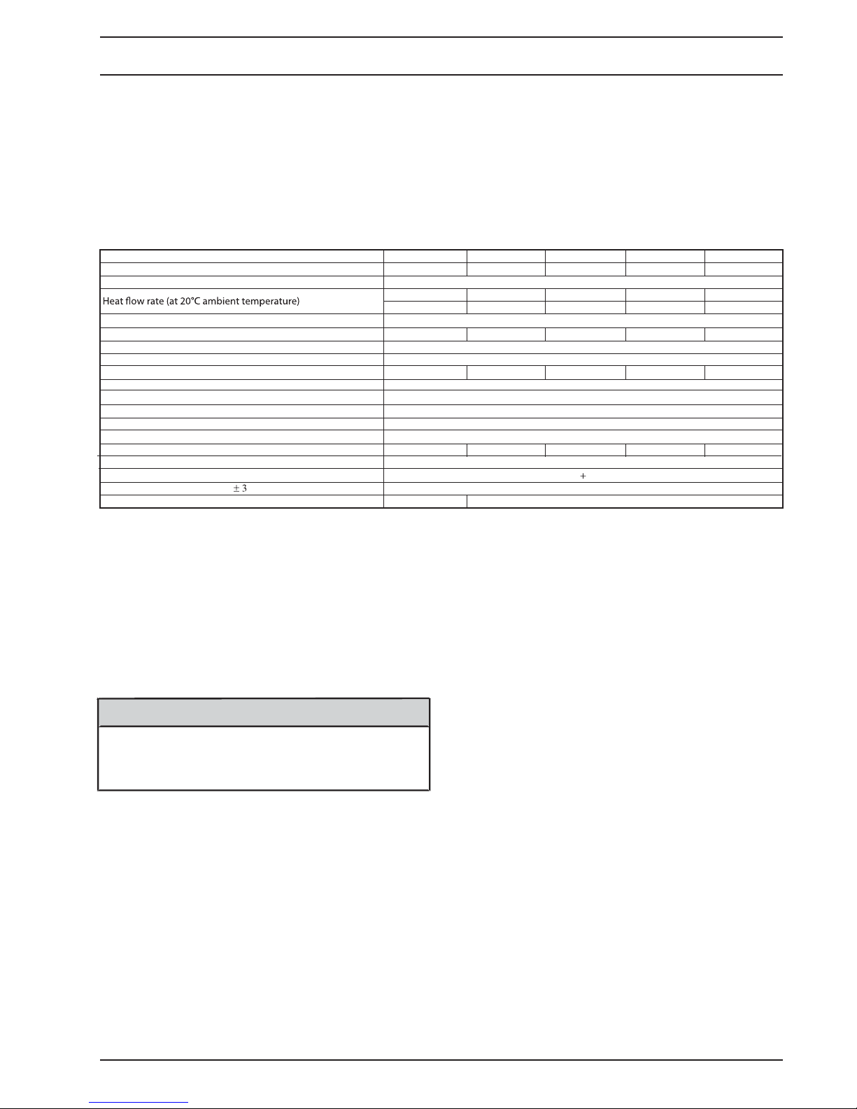
2 Technical data
Unless limiting values are de fined, the technical data
should be understood with tolerances of ±10% common
for heaters at an ambient temperature of 68° F (+20° C)
and at nominal voltage.
Table 201 Technical data
Design High-pressure atomizer
Fuel Diesel / light fuel oil
Electrical power consumption at 24 V Amps (W) 2.08 (50) 2.7 (65) 3.75 (90) 5.0 (120) 7.5 (180)
Max. permissible combustion air intake temperature
Permissible ambient temperature during operation
CO
2
Heater dimensions (tolerance
t lb (kg) 40.5 (18.4) 41.5 (18.8) hgieW
n Gal/h (kg/h) 0.51 (1.92) 0.79 (2.5) 0.95 (3.0) 1.14 (3.6) 1.29 (4.1)oitpmusnoc leuF
e US Quart (L) 1.9 (1.8)mulov gnillif regnahcxe taeH
e US Gallon (L) 10 (37.8) mulov noitalucric muminiM
mm) in (mm) 23.6” x 9.73” x 8.66” (600 x 247 x 220)
Btu/h 50,000 80,000 104,000 120,000 137,000
KW 16 23 30 35 40
42 Vegatlov lanimoN
03...02 Vegnar egatlov gnitarepO
°F (°C) 185 (85)
°F (°C) -40...+212 (-40...+100)
Permissible storage temperature °F (°C) -40...+230 (-40...+110)
Permissible operating pressure Psi (Bar) max. 29 (2.0)
5.9% loVagetlov lanimon ta tsuahxe ni 1.5
5220822072206220802000 R221 1E rebmun timrep epyt ECE
atadlacinhceT2004/053/003/032/061SomrehT
004SomrehT053SomrehT003SomrehT032SomrehT061SomrehTretaeH
002 ± 0023002 ± 0072002 ± 0042002 ± 0091002 ± 0041h/l… ±wolf retaw muminiM
* without circulating pump
Max. continuous current of the circulating pump 10 A, maximum peak current for 0.5 s duration = 90 A - We recommend the use o
efficiency and reliability. In order to reduce starting currents the circulating pump can be synchronized by the control unit f or a short time period during activation.
Confirm compatibility in case pumps provid ed by different manufacturers are used!
2.1 Electrical components
– Diesel -water emulsions: 0 .. - 5 °C without preheating
f Spheros circulation pumps for highest
system, - 10 .. - 15 °C with nozzle block preheater and
Control unit, circulating pump, solenoid valve, electronic
ignition and the digital timer are designed for 24V nominal
voltage. Motor nozzle block preheater and temperature
sensor voltages are controlled by the control unit.
NOTE
Recirculating pumps must be assigned to the heaters
according to the flow resistance in the coolant circulation
system. Voltages
directly app lied to the burner motor for
testing purposes may not exceed 12 V.
2.2 Fuel
heated fuel filter (use limitations depending on fuel
quality/water content).
– 100% Paraffin: - 10°C with nozzle block preheater and
heated fuel filter, the use of lubrication-improving
additives is recommended.
– Mixture of 70 Vol-% diesel fuel (winter diesel)
according to DIN EN 590 or DIN 51628 and 30 Vol-%
Bio diesel according to DIN EN 14214: - 5 .. - 10 °C
without preheating system, - 15°C with nozzle block
preheater a
nd heated fuel filter (use limitations
depending on fuel quality).
– Mixture of 75 Vol-% diesel fuel (winter diesel) according
to DIN EN 590 or DIN 51628 and 25 Vol-% vegetable oil
(rapeseed oil): 0 .. - 5 °C without preheating system,
Only fuels listed on the type plate as well as fuels
approved by Spheros may be used. The fuel use
limitations in the heater listed below must be observed.
– Diesel fuel according to DIN EN 590 and DIN 51628: The
limitations of use of the standard apply, hence winter
diesel down to - 20°C, Arctic diesel down to - 40°C
- 5 .. - 10 °C with nozzle block preheater and heated fuel
filter (use limitations depending on fuel quality).
– Mixture of 75 Vol-% diesel fuel according to DIN EN
590 or DIN 51628 and 25 Vol-% ethanol:
0 .. - 5 °C without preheating system, -5 .. - 10 °C with
with nozzle block preheate r and heated fuel filter
– Light fuel oil according to DIN 51603 (above 0°C)
– Bio diesel fuel according to DIN EN 14214: 0 .. - 5 °C
without preheating system, -10 .. - 15 °C with nozzle
block preheater and
heated fuel filte
r (use limitations
depending on fuel quality).
201

CAUTION
The listed temperature ranges, hence minimum
permissible temperatures strongly depend on the
respective fuel quality. In case of bad-quality fuel the
use limitations may deviate, e.g. in case of too high
water content.
At temperatures below 32°F (0°C ) commercially available
winter
diesel should be used. This especially applies for
fuel
extraction from a separate fuel tank.
The use of lubrication and flow improving additives is
permitted. No negative impact is known at time of the
preparation of this workshop manual.
CAUTION
When fuels are used, their respective limi
use must be observed and appropriate measures
(nozzle block preheater, electrically heated filter)
must be applied as needed.
In case fuel is extracted from the vehicle tank, the
vehicle manufacturer's mixing regulations shall apply.
tations of
omrehTatad lacinhceT2 S 160/230/300/350/400
202

Thermo S 160/230/300/350/400 3 Assemblies and components
3 Assemblies and components
descriptions
The Spheros Thermo S 160, S 230, S 300, S 350 and
S 400 water heater systems are used in conjunction with
the vehicle heating system
– to heat the passenger compartment
– to defrost the windows
– to preheat water-cooled vehicle engines.
The water heater operates independently from the vehicle
engine and is connected to the cooling system, the fuel
system and the electrical system of the vehicle. It is bolted
down to the vehicle chassis or is secured using an
additional cross beam.
3
2
Heat is generated by combusti on of liquid fuels. The heat
it transfe
heater's heat exchanger. In termittent operation adjusts
the heater to changing heat demand (cyclic operation).
The control unit controls heater activation and
deactivation based on the te mperature sensor signals.
The heaters of the Thermo S series mainly consist of the
following main components:
– Burner Head
– Combustion chamber
– Heat exchanger
A circulating pump is externally installed in the system, or
for compact devices directly on the heater.
rred to a coolant circulation system via the
4
5
Version for additional
sensor
10
12
11
13
1
6
7
9
8
1 Burner
2 Coolant, intake
3 Sensor plug
4 Temperature sensor with
integrated overheating protection
5 Coolant, outlet
6 Heat exchanger
7 Exhaust outlet
8 Fuel, return
9 Combustion air, intake
10 Fuel, flow
11 Splashguard
(screen alternative)
12 Screen
13 Hot air elbow
(incl. adapter)
(screen alternative)
301

3 Assemblies and components Thermo S 160/230/300/350/400
3.1 Burner
The burner consists of components
t Burner motor
t Combustion air fan
t Fuel pump with solenoid valve and atomiser nozzle
t Electronic ignition unit with ignition electrode
t Nozzle block preheater, optional
t Control unit with flame detector
t Disc with inspection glass
t Adapter wiring harness as interface to the
temperature sensor system
3.1.1 Combustion air fan
The combustion air fan transports the air required for
combustion from the combustion air intake to the
combustion chamber.
The combustion air fan consists
motor cross member. Air is
opening in the hood. The air intake opening is equipped
with a splashguard, a protective screen and a hot air
elbow.
Motor cross member
of burner motor, fan and
drawn in through the air intake
Coupling with
magnets
3.1.2 Fuel pump
The fuel pump is responsible for fuel supply.
The pump is driven by the burner motor via a coupling.
Fuel is compr
atomised via the atomiser nozzle.
The solenoid valve integrated into the fuel pump opens
and closes the fuel supply to the atomiser nozzle.
Three different fuel pumps are assigned to the different
heating capacity classes of the Thermo S series.
These are identified by the heating capacity class
specification as well as colour dots:
t 16 KW: 1 colour dot
t 23-35 KW: 2 colour dots
t 40 KW: 3 colour dots
essed in the fuel pump to approx. 10 bar and
Solenoid valve
Nozzle block
preheater (optional)
Burner motor
Shaft
circlip
Two dierent motors are assigned to the dierent heating
capacity classes of the The
heating capacity classes are indicated on the motor. In
addition the motors are dierentiated by colour.
t 16 kW - 30 KW: Motor housing
colour: silver
t 35 kW - 40 KW: Motor housing
colour: black
Fan
rmo S series. The respective
Screen
O-ring
Fuel pump
Colour dots for
identification
of the heating
capacity class
302
Thermo S 160/230/300/350/400 3 Assemblies and components
The fuel pump can be used in dual-line operation (fuel
supply and return line).
If the heater is operated with
– a long fuel supply line
– check valves in the fuel supply and return line
– a fuel filter in the fuel supply line
– single-line operation
the fuel supply line must be filled prior to first heater startup (see 8.14.1).
3.1.3 Nozzle block preheater
In case of very low temperatures fuel may exhibit severely
modified viscosity. Due to in sufficient fuel atomisation
functional heater malfunctions may occur.
Depending on the fuel used, these temperatures vary.
When used in
fuel are used, we recommend the use of a nozzle block
preheater.
The nozzle block preheater co nsists of a heating element
with an integrated temperature sensor.
At a temperature of < 5°C the heating element heats the
nozzle holder and thus, fuel and atomizer nozzle. Fuel
viscosity is reduced and atomisation improved.
The control unit defines the preheating time depending on
vehicle electrical system voltage and starting temperature.
cold regions or if fuels different from diesel
3.1.4 Control unit
The control unit 1586 ensures the operating sequence
and burner operation monitoring.
The flame detector is integrated into the control unit.
Different control units are assigned to the different heating
capacity classes.
The control units are assigned via the ID number and the
performance class indicated on the type plate of the
control unit.
Type plate with
ID number and
heating capacity
class identification
Control unit 1586
The use of the nozzle block preheater is optional. It is
possible to
the control unit.
retrofit this capability without modifications to
Heating element
Nozzle block preheater
Flame detector
3.1.4.1 Flame detector
The flame detector monitors the flame conditions during
heater operation.
e fame detector is a photo
Th
resistance as a function of flame luminous intensity and
thus, the voltage applied.
transistor, which changes its
303
3 Assemblies and components Thermo S 160/230/300/350/400
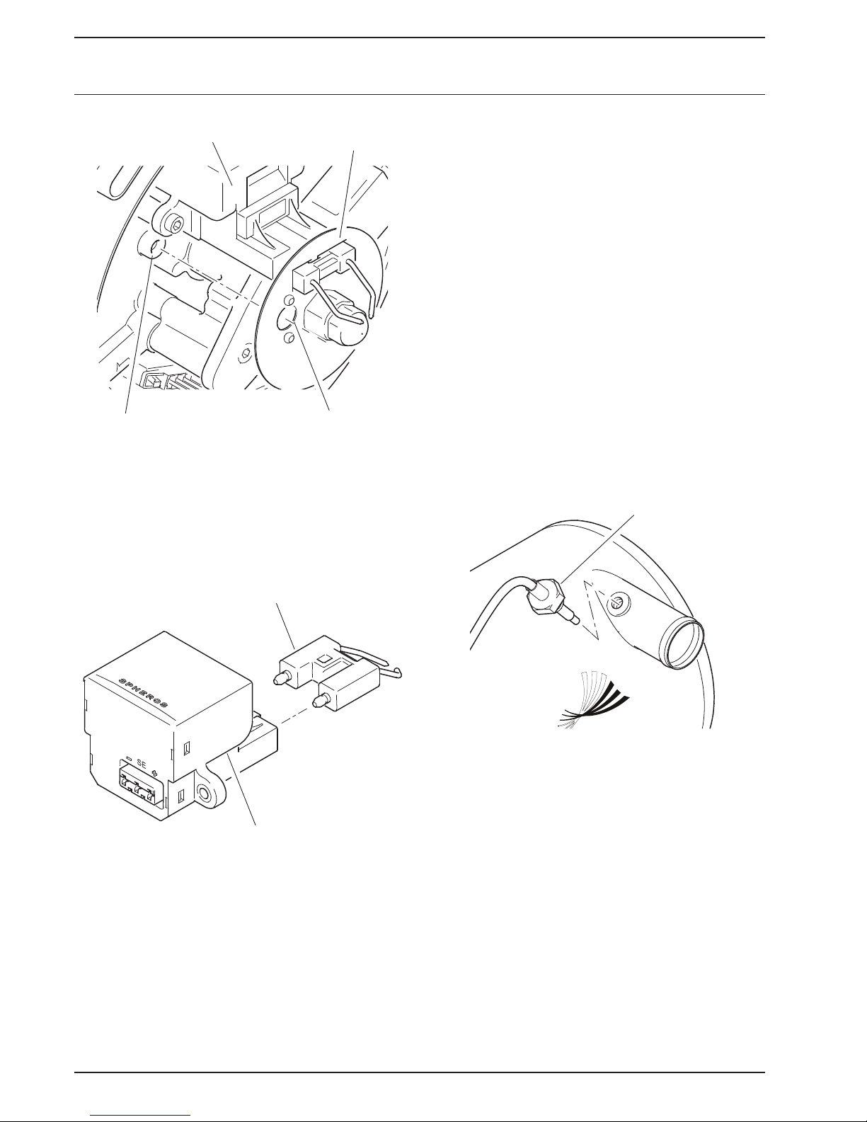
3.1.6 Temperature sensors with water
Electronic ignition unit
Flame detector
Disc
Window
3.1.5 Electronic ignition unit with ignition
electrodes
The electronic ignition unit induces the high voltage
required for ignition of the fuel-air mixture. Ignition is
triggered by a high voltage spar k, which is initiated on the
ignition electrode.
The water temperature sensor captures the coolant
temperature at the heat exchanger outlet as electrical
resistance.
This signal is transmitted to the control unit, where it is
processed.
The overheating protection integrated into the temperature
sensor is responsible for temperature limitation.
Similar to the water temperature sensor, the coolant
temperature is captured at the heat exchanger outlet as
electrical resistance and transmitted to the control unit.
Overheating protection prevents inadmissibly high heater
operating temperatures.
At a temperature greater than 125°C heater deactivation
and interlocking is initiated.
It is not necessary to man ually reset the overheating
protection.
temperature sensor and integrated
overheating protection
Temperature
sensor
Ignition electrode
Electronic ignition unit
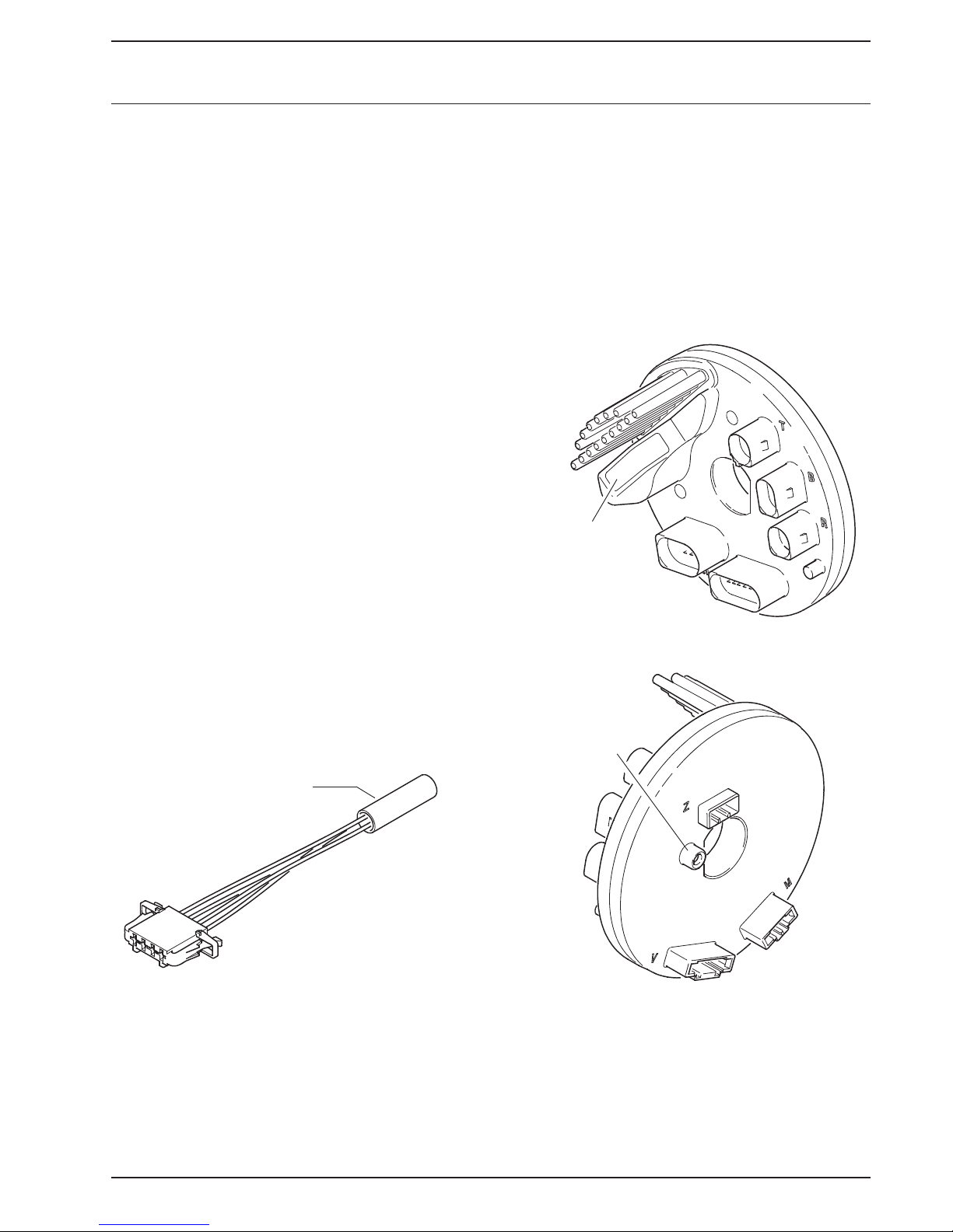
3.1.6.1 Adapter wiring harness
It is possible to disconnect the temperature sensor plug
from the adapter wiring harness. Thus, the hood does not
need to be removed for burn
er head removal.
304
Thermo S 160/230/300/350/400 3 Assemblies and components
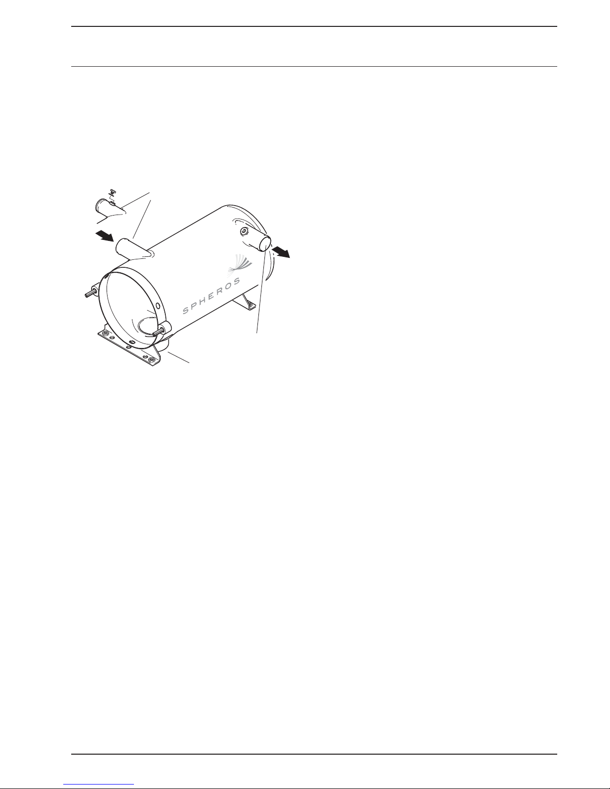
3.2 Heat exchanger
The heat exchanger transfers the heat generated by
combustion to the coolant circulation system.
Depending on the system integration a heat exchanger
with or without thread in the coolant inlet socket can be
installed.
Coolant inlet
Coolant outlet
Exhaust outlet
305
3 Assemblies and components Thermo S 160/230/300/350/400
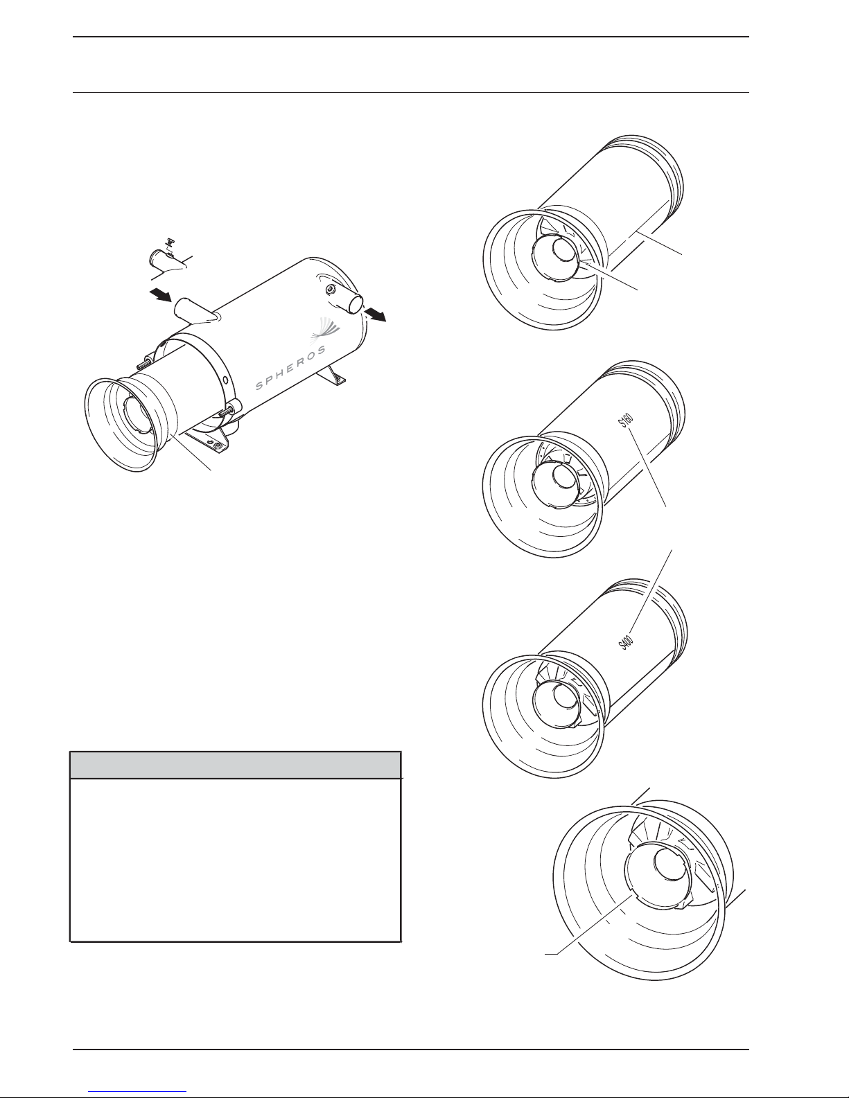
3.3 Combustion chamber
The combustion chamber is used for generation and
combustion of the fuel air mixture. The generated exhaust
gas heats the coolant flowing through the heat exchanger.
23 - 35 KW
Welding seam
Swirl plate
16 KW
Combustion chamber
Three different combustion chambers are used for heaters
of the Thermo S series. Deviating from the standard
combustion chamber variant for Thermo S 230, S 300 and
S 350, the Thermo S 160 is equipped with a combustion
chamber with a sheet metal swirler and the Thermo S 400
is equipped with a burner pipe with increased wall
thickness (1.5 mm).
The combustion chambers of Thermos S 160 and Thermo
S 400 are each fitted with a stamping to di
individual combustion chambers.
NOTE
If possible, the combustion chamber should be inserted
into the heat exchanger in such a way, that the burner
pipe welding seam is between 60° and 300° in the lower
area.
At the same time it must be ensured that none of the
4 cut-outs of the combustion-chamber head points
vertically downwards (see figure on the right).
It is permissible to change t he position during maintenance
or after combustion chamber r eplacement vs. the previous
installation position.
stinguish the
Identication
of the heating
capacity class
40 KW
Cut-out positions
on the combustion
chamber head
in installe d condition
306
Thermo S 160/230/300/350/400 3 Assemblies and components
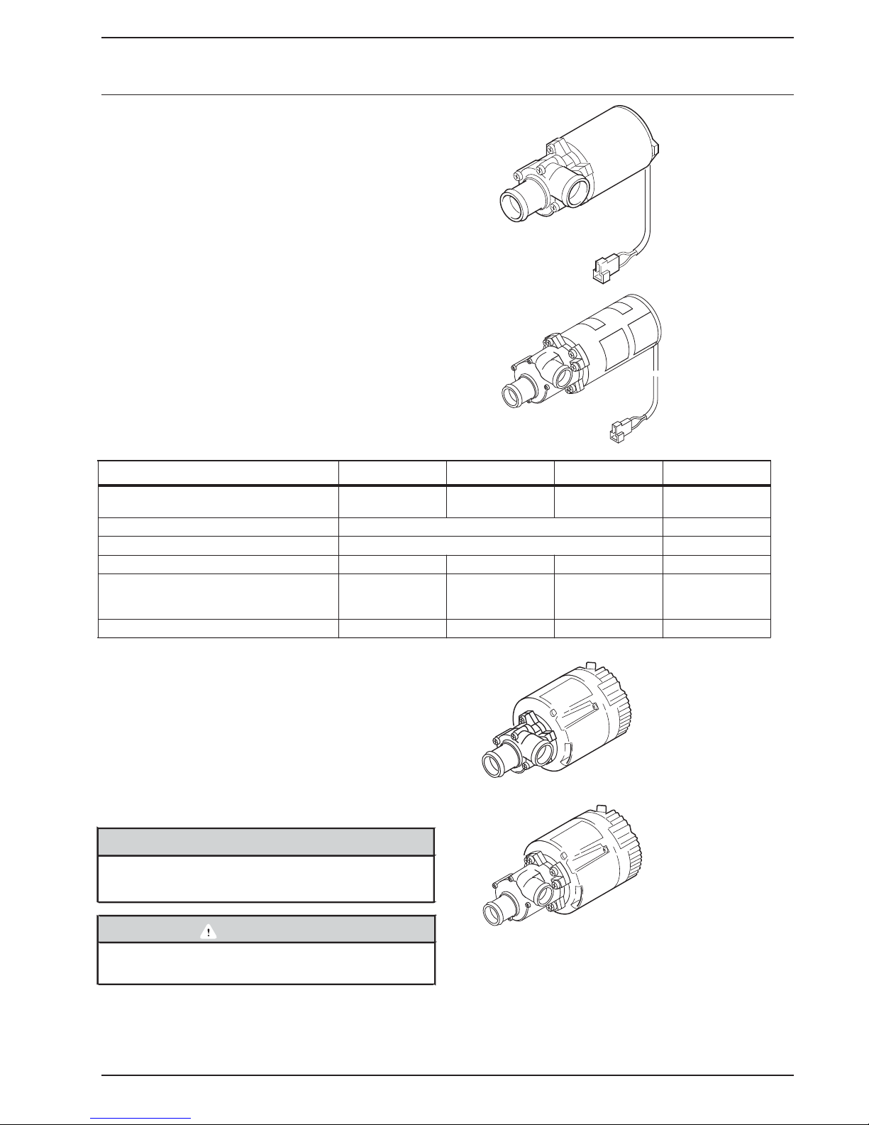
3.4 Circulating pump
Aquavent 5000
The externally arranged circulating pump ensures coolant
transport within the vehicle and/or heater circulation
system.
Depending on the application, the circulating pump is
switched on via the control unit or directly via the vehicle
electrical system and operated during the entire heater
operation duration.
Heaters can be operated wit h Aquavent 5000 (U4814),
Aquavent 5000S (U4854), Aquavent 6000C (U4855) or
Aquavent 6000SC (U4856) circulating pumps.
(U4814)
Aquavent 5000S
(U4854)
h/lwolf fo emuloV
US Gal/m
Nominal power consumption Watts 104 104 210 210
).ni( mmsnoisnemiD
mm (in.)
mm (in.)
5200
23
Length 229 (9)
Width 100 (3.9)
Height 105 (4.1)
5200
6000 6000
23
26.4 26.4
12 ... 24stloVegatlov lanimoN
10 ...14/20 ... 28stloVegatlov gnitarepO
Length 249 (9.8)
Width 100 (3.9)
Height 105 (4.1)
Length 224 (8.8)
Width 115 (4.5)
Height 110 (4.3)
Length 229 (9)
Width 115 (4.5)
Height 110 (4.3)
The safety device of the circulating pump may never be
lled, while the pump is running, and may not be
pu
replaced, when the pump is switched on.
Aquavent 6000C
(U4855)
3.4.1 Aquavent 5000 (U4814) and Aquavent
5000S (U4854) circulating pumps
The Aquavent 5000 (U4814) and 5000S (U4854)
circulating pumps are equipped with a brush motor.
NOTE
Aquavent 5000 (U4814) with floating-ring type shaft seal.
Aquavent 5000S (U4854) magnetic drive (no seal)
Aquavent 6000SC
(U4856)
SC 0006 tnevauqA Aquavent 6000C S 0005 tnevauqA Aquavent 5000 pmup gnitalucriC
5.5 (2.5) 5.3 (2.4)4.8 (2.2) (2.1) .4.6 thgieW
CAUTION
The circulating pump motor is not equipped with an
internal inverse-po
larity protection
307

3 Assemblies and components Thermo S 160/230/300/350/400
3.4.2 Aquavent 6000C (U4855) and Aquavent
6000SC (U4856) circulating pumps
The Aquavent 6000C (U4855) and
Aquavent 6000SC (U4856) circulating pumps are
equipped with a brushless motor.
Inverse-polarity protection
The circulating pump motor is not equipped with an
internal inverse-polarity protection.
3.5 Fuel filter
NOTE
The Aquavent 6000C (U4855) has a floating-ring type
shaft seal.
The Aquavent 6000SC (U4856) is equipped wit a
magnetic coupling (no seal)
Soft start
The circulating pump motor starts slowly and gently. Max.
rotational speed is only reached after approx. 5 seconds.
Protection against dry running
Protection against dry running is integrated into the
circulating
If the circulating pump motor consumes within a time
period of approx. 45 minutes significantly less current, dry
running is detected. The circulating pump motor is
switched off.
After approx. 2 minutes and circulating pump motor
reactivation, the operation can be continued.
Blocking protection
If the pump wheel is blocked, the motor will be switched
off via the error mode directly prior to standstill of the
pump wheel.
pump motor.
A heatable fuel filter is available as an option. The
temperature switch switches the integrated filter heating
on at a temperature of <
a temperature of <
0.5 ± 2.5 °C and switches it off at
5.5 ± 2.5 °C.
Overload protection
Overload protection is activa ted after the soft start is
completed. The current consumption will be limited.
In case of hydraulic ove
pump, the circulating pump motor will not be damaged.
Error mode
In case of malfunctions the circulating pump motor is
switched off via the error mode. After approx. 5 seconds
the error mode switches the circulating pump motor into
energy-saving sleep mode.
Sleep mode
In sleep mode internal electronics consumers of the
circulating pump motor are switched off.
Reactivation of the circulating pump motor
It is possible to reactivate the circulating pump motor from
sleep mode. For this purpose the power supply is
disconnected fo
reconnected, the circulating pump motor restarts in softstart mode.
r > 2 min. Af ter the power supply is
rpressuring of the circulating
308
snoitcnuf retaeH4004/053/003/032/061 SomrehT
4 Heater functions
4.1 General heater functionality
description
The heater principle is based on a high-pressure atomizer
burner and is monitored by an integrated control unit.
The burner motor powers the fan and the fuel pump. The
fuel pump is coupled to the motor using a plastic coupling.
The fan produces the required combustion air, the combustion
air volume is impacted by the burner motor speed.
The speed is monitored by a sensor in the control unit, which
analyses the changing magnetic field of the magnets in the
couplings.
The speed required for the CO
first calibration at Sphero
In a maintenance event the workshop can adjust the CO
setting using the STT diagnosis (Spheros-Thermo-TestDiagnosis) (see 4.2).
The fuel pressure is generated in the fuel pump and reduced
to the required pressure using a pressure limiting valve.
A solenoid valve releases the fuel via the atomizer nozzle
for combustion in the combustion chamber.
-content is determined during
2
s and is stored in the control unit.
-
2
As an option, the fuel pump can be equipped with a nozzle
block
block preheater. The nozzle
preheater heats the
nozzle holder with the atomizer nozzle at low temperatures,
and thus the fuel. Th
e fuel air mixture is ignited in the
combustion chamber via a high-voltage ignition spark.
The flame is monitored by a flame detector integrated into
the control unit.
Depending on the equipment, the heater is switched on
and off using a
t digital timer
t switch
t or climate control.
During heating operation the burner is automatically
switched on and off. The heater is switched on, when the
temperature falls short of a lower temperature threshold,
and is switched off, if the upper temperature threshold is
reached (see table 401).
The switching
and the heating operation type. They cannot be changed
and are programmed into the control unit.
For overheating protection of the heater the switching
thresholds are modified by the control unit, if specified
temperature gradients are exceeded.
If the specified minimum burning duration is not reached,
the switching thresholds will be reduced. This protects the
heater against sooting of the heat exchanger.
thresholds depend on the heater variant
An operating display is available for monitoring the operating
status. A flame indication can be optionally installed.
The operating display is also used to output error
messages in flash code.
so possible to read the flash code via the two-pin
It is al
plug in the heater wiring harness (see 4.7 and 5.3).
Use max. 2W lamps.
Table 401 Standard switching thresholds
Standard
Lower switching threshold: auxiliary heating in °F (°C) 172 (78)
Upper switching threshold: auxiliary heating in °F (°C) 185 (85)
Lower switching threshold: normal mode parking heating in °F (°C) 158 (70)
°
Upper switching threshold: normal mode parking heating in °F (
Lower switching threshold: saving mode 1 parking 131 (55)
heating in °F (°C)
Upper switching threshold: saving mode 1 parking 158 (70)
heating in °F (°C)
Lower switching threshold: saving mode 2
heating in °F (°C)
Upper switching threshold: saving mode 2 parking 140 (60)
heating in °F (°C)
parking 113 (45)
C) 185 (85)
Switching thresholds may deviate
NOTE
per customer.
401
mrehTsnoitcnuf retaeH4 o S 160/230/300/350/400
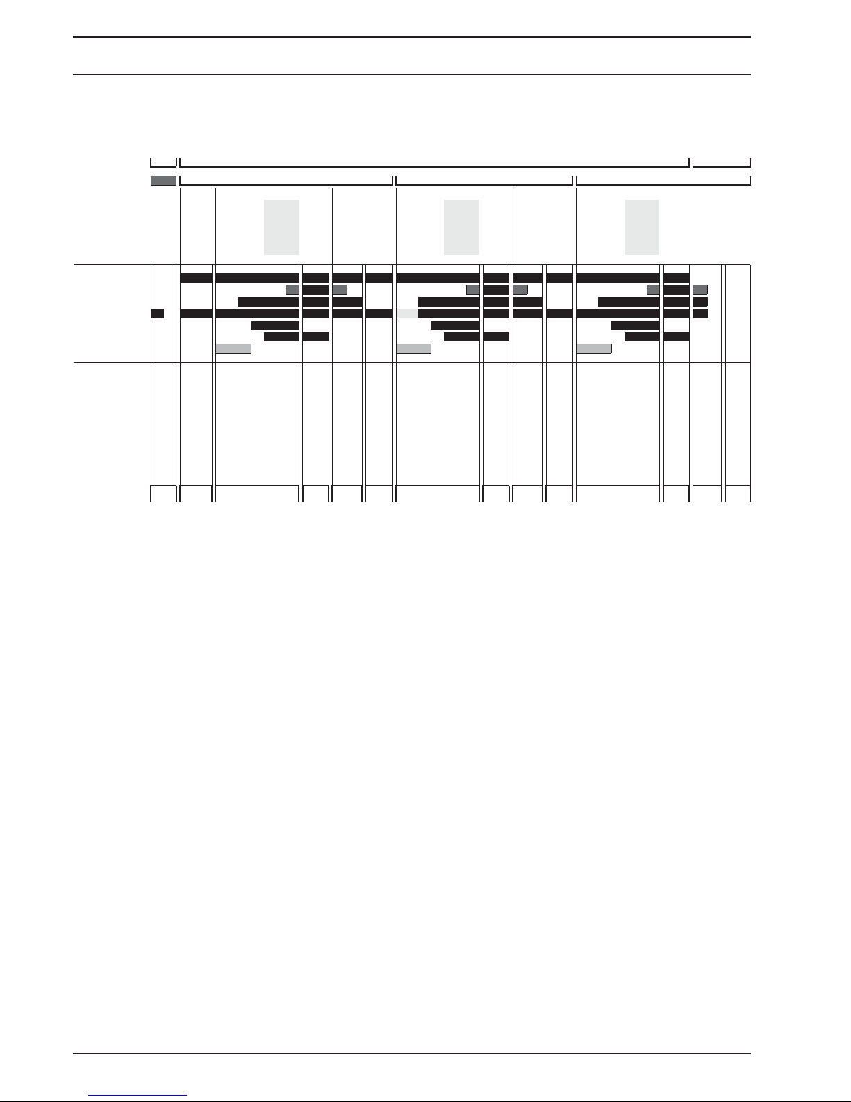
4.2 Operational heater sequence
Signals
Main switch o on o
Terminal 61
Tnim_T < Tnim_T > Terutarepmet tnalooC
nim_T < Txam_T => Tnim_T < Txam_T =>
)gnitaeh gnikrap( ffo)gnitaeh yrailixua( no)gnitaeh gnikrap( ffo
Flame
Initial cycle with light check
generation
Pre-ignition
Ignition
Stabilisation
Run-down with safety period
Run-down 2
down
Optional nozzle block
Standby Start Heating Run-
preheating
UPFA on
Actuators
Operating display
Flame display
Combustion air motor
Circulating pump
Electronic ignition unit
Solenoid valve
Nozzle block preheater
Time in s 0..108 12 1 0..15 5 ... 30 90 0..108 12 1 0..15 5 ... 30 90 0..108 12 1 0..15 5 ... 30 90
State
UPFA o
Look for
Optional nozzle block
OFF Standby Start Heating Run-
preheating
Initial cycle with light check
Flame
generation
Pre-ignition
Ignition
Stabilisation
Run-down with safety period
Run-down 2
down
Optional nozzle block
Standby Start Heating Run-
preheating
Initial cycle with light check
Flame
generation
Pre-ignition
Ignition
Stabilisation
Fig. 403 Operational sequence
4.2.1 Switching on and start
voltage the preheating time is determined. The duty cycle
is limited to a maximum of 120 seconds.
When switched on, the operating display is illuminated,
the control unit starts controlled operation and checks the
coolant temperature.
The burner motor does not run during the entire
preheating time. It starts latest 12 seconds prior to
expiration of the determined preheating time during initial
cycle.
If the coolant temperature is below the upper temperature
threshold, the initial cycle starts.
Combustion air fan and circulating pump are switched on.
The initial cycle time can be extended to a maximum of
120 seconds.
The further sequence takes place as described.
Run-down with safety period
down
Run-down 2
O
After approx. 12 seconds (initial cycle time) the highvoltage spark is ignited. Approx. 1 second later the
solenoid valve in the fuel pump is opened.
The fuel injected via the atomizer nozzle and mixed with
the air of the combustion air fan, is
ignited by the ignition
spark and burned in the combustion chamber.
The flame is monitored by a flame detector integrated into
the control unit.
A few seconds after a flame is detected, the control unit
switches the electronic ignition unit off. Until then the
flame is stabilised. The heater is not yet in heating mode.
With optional nozzle block preheater:
The integrated temperature sensor determines the
temperature on the nozzle holder as soon as the initial
cycle starts. Starting at a temperature of < 5°C the nozzle
block preheater is switched on. Depending
determined temperature and the vehicle electrical system
402
on the
4.2.2 Heating operation
After the flame is stabilised, the heater is in controlled
(normal) operation.
Depending on the coolant tempe
temperature is maintained at one level by switching the
burner alternately on and off.
Once the upper switching threshold is exceeded, heating
operation is finished and run-down initiated.
The solenoid valve is closed, the flame expires, however the
combustion air fan and circulating pump continue running.
The run-down ends approx. after 120 seconds. The
combustion air fan is switched off.
The heater is in a controlled break.
The operating disp lay is illuminated.
rature, the coolant
 Loading...