

Spheros thermo 230, thermo 300, thermo 350, thermo 301, thermo 231 Workshop Manual

Water Heaters Workshop Manual
Thermo 230
Thermo 300
Thermo 350
with control unit 1572
model .30 and up
Thermo 230
Thermo 300
Thermo 350
with control unit 1572D
model .030 and up
Thermo 231
Thermo 301
model .01 and up
Thermo Rail
12/2012
Ident Nr. 9003656C II


Thermo 230 / 231 / 300 / 301 / 350 List of Contents
List of Contents
1. Introduction
1.1 Scope and Purpose ............................................................................................................................... 101
1.2 Applicability of Manual ........................................................................................................................... 101
1.3 Meaning of Warnings, Cautions and Notes ........................................................................................... 101
1.4 Additional Documentation to be used .................................................................................................... 101
1.5 Safety Information and Regulations....................................................................................................... 101
1.5.1 General Safety Notes ................................................................................................................. 101
1.6 Legal Provisions for Installation ............................................................................................................. 102
1.7 Corrections and Improvements.............................................................................................................. 103
2. General Description
2.1 Combustion Air Fan ............................................................................................................................... 202
2.2 Fuel Pump ............................................................................................................................................. 202
2.2.1 Nozzle block preheater............................................................................................................... 203
2.3 Heat Exchanger ..................................................................................................................................... 203
2.4 Combustion Chamber............................................................................................................................ 203
2.5 Control Unit............................................................................................................................................ 203
2.6 Flame Sensor ........................................................................................................................................ 203
2.7 Igniter Box with Igniter Electrodes ......................................................................................................... 203
2.8 Temperature Sensor.............................................................................................................................. 204
2.9 Temperature Limiter .............................................................................................................................. 204
2.10 Overheat Thermostat (Thermo 231 and 301 only) ................................................................................ 204
2.11 Circulation Pump ................................................................................................................................... 204
2.11.1 Aquavent 5000 (U4814) and Aquavent 5000S (U4854) circulating pumps................................ 205
2.11.2 Aquavent 6000C (U4855) and Aquavent 6000SC (U4856) circulating pumps............................205
2.12 Fuel Filter............................................................................................................................................... 206
3. Functional Description
3.1 Switch On .............................................................................................................................................. 302
3.2 Heating Operation.................................................................................................................................. 302
3.3 Switch Off .............................................................................................................................................. 303
3.4 Power Save ........................................................................................................................................... 303
3.5 Auxiliary Heating Operation (heaters with control unit 1572D only) ...................................................... 303
3.6 Heater Lockout (heaters with control unit 1572D only).......................................................................... 303
3.7 Switch-off upon Failure (heaters with control unit 1572)........................................................................ 303
3.8 Switch-off upon Failure (heaters with control unit 1572D) ..................................................................... 305
3.9 Error Code Output (heaters with control unit 1572D) ............................................................................ 306
4. Technical Data
Electrical components...................................................................................................................................... 401
Propellant......................................................................................................................................................... 401
I

List of Contents Thermo 230 / 231 / 300 / 301 / 350
5. Troubleshooting
5.1 General ................................................................................................................................................. 501
5.2 General Fault Symptoms ...................................................................................................................... 501
5.3 Fault Symptoms during Functional Checkouts and Error Code Output or Tests with
Diagnostic Computer, Components Tester or PC Heater Diagnosis .................................................... 503
5.3.1 General...................................................................................................................................... 503
5.3.2 Fault Symptoms......................................................................................................................... 504
6. Functional Checkouts
6.1 General ................................................................................................................................................. 601
6.2 Adjustments .......................................................................................................................................... 601
6.2.1 Adjustment of CO2 Contents ..................................................................................................... 601
6.3 Components Testing............................................................................................................................. 602
6.3.1 Temperature Sensor Resistance Check.................................................................................... 602
6.3.2 Flame Sensor Resistance Check .............................................................................................. 602
6.3.3 Igniter Electrodes Check ........................................................................................................... 602
6.3.4 Igniter Box Check ...................................................................................................................... 603
6.3.5 Fuel Pump Check ...................................................................................................................... 603
6.3.6 Fan Motor Check ....................................................................................................................... 604
6.3.7 Solenoid Valve Check ............................................................................................................... 604
6.3.8 Nozzle Block Preheater Check.................................................................................................. 604
7. Circuit Diagrams
7.1 General ................................................................................................................................................. 701
8. Servicing
8.1 General ................................................................................................................................................. 801
8.2 Heater Servicing ................................................................................................................................... 801
8.3 Vehicle Servicing .................................................................................................................................. 801
8.4 Heater Test Run.................................................................................................................................... 801
8.5 Maintenance ......................................................................................................................................... 801
8.5.1 Inspection and Attachment of the Exhaust Muffler (only heaters from year of
production 1996 and up to production date 1996, calendar week 36; 3G......) .......................... 801
8.5.2 Burner Head Opening and Closing or Removal and Installation ............................................... 803
8.6 Visual Inspections and Regulations for Installation............................................................................... 804
8.6.1 Connection to Vehicle Cooling System ..................................................................................... 804
8.6.2 Connection to Vehicle Fuel System........................................................................................... 804
8.6.3 Combustion Air Supply .............................................................................................................. 806
8.6.4 Exhaust Line.............................................................................................................................. 806
8.7 Removal and Installation....................................................................................................................... 807
8.7.1 Heater, Removal and Installation .............................................................................................. 807
8.7.2 Temperature Limiter, Replacement ........................................................................................... 807
8.7.3 Temperature Sensor, Replacement .......................................................................................... 807
8.7.4 Burner, Replacement................................................................................................................. 807
II

Thermo 230 / 231 / 300 / 301 / 350 List of Contents
8 7.5 Igniter Box, Replacement ........................................................................................................... 807
8.7.6 Flame Sensor, Replacement ...................................................................................................... 808
8.7.7 Combustion Chamber, Replacement ......................................................................................... 808
8.8 First Operation ....................................................................................................................................... 808
8.8.1 Water Circuit, Bleeding............................................................................................................... 808
8.8.2 Fuel Supply System, Bleeding.................................................................................................... 808
9. Repair
9.1 General .................................................................................................................................................. 901
9.1.1 Work on Components after Disassembly ................................................................................... 902
9.1.2 Incorporation of Modifications..................................................................................................... 902
9.2 Disassembly and Assembly................................................................................................................... 906
9.2.1 Temperature Limiter, Replacement ............................................................................................ 904
9.2.2 Temperature Sensor, Replacement ........................................................................................... 904
9.2.3 Burner, Replacement.................................................................................................................. 904
9.2.4 Combustion Air Fan, Replacement............................................................................................. 906
9.2.5 Control Unit, Replacement ......................................................................................................... 908
9.2.6 Fuel Pump, Replacement ........................................................................................................... 908
9.2.7 High Pressure Nozzle, Replacement...........................................................................................908
9.2.8 Igniter Box, Replacement ........................................................................................................... 910
9.2.9 Flame Sensor, Replacement ...................................................................................................... 910
9.2.10 Heat Exchanger, Replacement................................................................................................... 912
9.2.11 Combustion Chamber, Replacement ......................................................................................... 912
10. Packaging, Storage and Shipping
10.1 General................................................................................................................................................ 1001
Annex A
Heater, Scheduled Maintenance...................................................................................................................... A-2
III

List of Contents Thermo 230 / 231 / 300 / 301 / 350
List of Figures
301 Functional Sequence (heaters with control unit 1572) .................................................................................... 304
302 Functional Sequence (heaters with control unit 1572D) ................................................................................. 305
501 General Fault Symptoms ................................................................................................................................ 501
701 Automatic Control Circuit with Control Unit 1572 and Switch ......................................................................... 702
702 Automatic Control Circuit with Control Unit 1572 and Timer (Triple Timer) .................................................... 703
703 Automatic Control Circuit with Control Unit 1572D and Switch....................................................................... 704
704 Automatic Control Circuit with Control Unit 1572D and Standard Timer......................................................... 705
705 System Circuit Daimler Chrysler Citaro, Ident.-Nr. 67131................................................................................ 706
706 System Circuit Van Hool, Ident.-Nr. 89401 ...................................................................................................... 707
707 System Circuit O405 / O407 / O408, Ident.-Nr. 91292..................................................................................... 708
708 System Circuit MAN, Ident.-Nr. 89404 ............................................................................................................. 709
709 System Circuit SETRA, Ident.-Nr. 90972 ......................................................................................................... 710
710 Automatic Control Circuit Rail with Control Unit 1572D and Standard Timer and filter heater ........................ 711
801 Swinging Burner Head open ........................................................................................................................... 803
802 Example of a Heater Installation in a Passenger Bus ..................................................................................... 805
901 Temperature Limiter, Temperature Sensor and Burner, Replacement........................................................... 905
902 Combustion Air Fan, Replacement ................................................................................................................. 907
903 Control Unit and Fuel Pump, Replacement..................................................................................................... 909
904 Igniter Box and Flame Sensor, Replacement ................................................................................................ 910
905 Heat Exchanger and Combustion Chamber, Replacement ............................................................................ 912
IV

Thermo 230 / 231 / 300 / 301 / 350 1 Introduction
1. Introduction
1.1 Scope and Purpose
This repair shop manual is intended to support
familiarized personnel in the repair of water heaters
Thermo 230, 231, 300, 301 and 350.
The water heater may only be operated with the specified
fuel (Diesel or also fuel oil EL) and the relevant designated
type of electrical connection.
1.2 Applicability of Manual
This manual is applicable only for heaters identified on the
title page. The different appearance of control units (see
2.5) allow to distinguish between model .30 and up with
control unit 1572 and the model .030 and up with control
unit 1572D.
In combination with control unit 1572D additionally a
different type of igniter box is installed (refer to 2.7).
The heaters Thermo 231 and 301 are variants for vertical
installation.
1.3 Meaning of Warnings, Cautions and
Notes
WARNINGS, CAUTIONS, and NOTES in this manual
have the following meaning:
WARNING
This heading is used to highlight that non-compliance with
instructions or procedures may cause injuries or lethal
accidents to personnel.
1.4 Additional Documentation to be used
This workshop manual contains all information and
procedures necessary for the repair of heaters Thermo
230, 231, 300, 301 and 350 as well as Thermo Rail.
Operating instructions and installation instructions may be
used as complementary information as necessary.
1.5 Safety Information and Regulations
The general safety regulations for the prevention of
accidents and the relevant operating safety instructions
have to be observed at all times.
"General Safety Regulations" beyond the scope of these
regulations are detailed in the following.
The specific safety regulations applicable to this manual
are highlighted in the individual chapters by Warnings,
Cautions, and Notes.
1.5.1 General Safety Notes
The year of first operation must be permanently
marked on the identification label by removing the
relevant number of the year.
The heaters are cleared for heating the vehicle engine
and the passenger cabin. The use of the heater in
vehicles not subject to the EU Directive 70/156/EEC (e.g.
ships) is partly governed by regional regulations.
For heaters designed for installation in rail vehicles, type
approval has been granted (not for Thermo 231 and 301)
by the Federal Railway Authority with the type approval
number: EBA 32AZ3/0174/08.
The heater may only be fitted in vehicles or in independent
heating systems with a minimum coolant capacity of
10 liters.
CAUTION
This heading is used to highlight that non-compliance
with instructions or procedures may cause damage to
equipment.
NOTE
This heading is used to highlight and draw specific
attention to information.
The heater may only be installed in motor vehicles or in
independent heating systems with a minimum coolant
capacity of 6 liters.
The heater must not be installed in the passenger or driver
compartments of vehicles. Should the heater neverthe
less be installed in such a compartment, the installation
box must be sealed tight against the vehicle interior.
There must be sufficient ventilation of the installation box
from the exterior in order not to exceed a maximum
temperature of 85 °C in the installation box. Excessive
temperatures may cause malfunctions.
WARNING
Due to the danger of poisoning and suffocation the
heater must not be operated, not even with timed
operation, in enclosed areas such as garages or
workshops not equipped with an exhaust venting
facility.
-
101

1 Introduction Thermo 230 / 231 / 300 / 301 / 350
At filling stations and fuel depots the heater must be
switched off to prevent explosions.
CAUTION
Where flammable fumes or dust may build up (e.g. in
the vicinity of fuel, coal, wood, cereal depots, or
similar installations) the heater must be swit ch e d off
to prevent explosions.
The heater must not be operated near flammable materials such as dry grass and leaves, cardboard
boxes, paper, etc.
In the vicinity of the water heater a temperature of 110 °C
(storage temperature) must not be exceeded under any
circumstances (e.g. during body paint work).
A violation of this temperature limit may cause permanent
damage to the electronics.
When checking the cooling water level proceed in
accordance with the vehicle manufacturer’s instructions.
The water in the heating circuit of the heater must contain
a minimum of 10% of a quality brand anti-freeze.
Additives in the heating circuit must not affect metals,
plastics and rubber and must leave no deposits.
The opening pressure in the vehicle cooling system normally indicated on the radiator filler cap - must be
between 0.4 and 2.0 bar above operating pressure (also
applicable to separate heating circuits).
1.6 Legal Provisions for Installation
(Extract from Directive 2001/56/EC Annex VII)
1.7.1. A clearly visible indicator within the user's field of
vision must show when the heater is switched on or off.
NOTE:
For further notes and provisions relating to the installation
of the heater in vehicles, refer to the installation instructions.
IMPORTANT
Failure to follow the installation instructions and the notes
contained therein will lead to all liability being refused by
Spheros. The same applies if repairs are carried out incorrectly or with the use of parts other than genuine spare
parts. This will result in the invalidation of the type approval for the heater and therefore of its homologation / EC
type licence.
Installation Instructions for Spheros fuel tanks for the fuel
supply of water heaters in vehicles:
• in busses and trains the installation is not permitted in
the passengers’ or driver’s compartment.
• the fuel filler neck must not be located in the passengers’ or driver’s compartment of any vehicle.
• fuel containers must either be equipped with a vent
cap or any other type of ventilation (vent line).
Only vent caps in accordance with DIN 73400 may be
used.All fuel containers offered in the Spheros Accesso
ries Catalogue are suitable for a maximum operating pressure of 0.15 bar overpressure.
-
With effect from 4/03, Type Approvals pursuant to EC Directives 72/245/EEC (EMC) and 2001/56EC (Heating Systems) were granted for the heaters Thermo 230 / Thermo
231 / Thermo 300 / Thermo 301 / Thermo 350 with the following EC Type Approval Numbers:
e1*72/245*95/54*1010*-e1*2001/56*0007*-- for Thermo 230
e1*2001/56*0008*-- for Thermo 300
e1*2001/56*0009*-- for Thermo 350
e1*2001/56*0010*-- for Thermo 231
e1*2001/56*0011*-- for Thermo 301
Up to 4/03, General Design Certifications existed for these
heaters.I
nstallation is governed above all by the provisions in
Annex VII of Directive 2001/56/EC.
NOTE:
The provisions of these Directives are binding within
the territory governed by EU Directive 70/156/EEC
and should similarly be observed in countries without
specific regulations.
All fuel containers offered in the Spheros Accessories Catalogue are subjected during manufacture to individual
pressure testing with at least 0.3 bar overpressure.
• The operational state of the heater, i.e. at least an
indication "on" or "off" must be easily and clearly visi
ble.
For heaters in vehicles not ruled by the EU Directive but
other regulations, the acceptance by the relevant authority is required as applicable.
-
102

Thermo 230 / 231 / 300 / 301 / 350 1 Introduction
1.7 Corrections and Improvements
Deficiencies, improvements, or proposals for correction of
this workshop manual are to be mailed to:
Spheros GmbH
Friedrichshafener Straße 9 - 11
D-82205 Gilching
Telefon: +49 (0)8105 7721 887
Telefax: +49 (0)8105 7721 889
www.spheros.de / service@spheros.de
103

1 Introduction Thermo 230 / 231 / 300 / 301 / 350
Page empty for notes
104
Thermo 230 / 231 / 300 / 301 / 350 2 General Description
2 General Description
The water heaters Spheros Thermo 230, 231, 300, 301
and 350 are used in combination with the vehicle’s own
heating installation to
– heat the passenger compartment
– defrost the windscreen
– preheat water-cooled engines
The heaters Thermo 231 and 301 are variants for vertical
installation. The difference in appearance are the different
identification label and the Z profiles on the installation interface.
The water heater operates independent from the vehicle
engine and is connected to the vehicle cooling system,
fuel system and the electrical system.
the
The heater designed to the heat exchanging principle
operates intermittently controlled by the temperature
sensor.
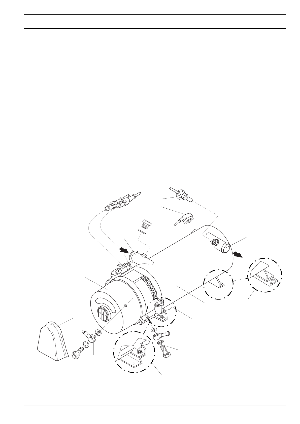
The heaters Thermo 230, 231, 300, 301 and 350 basically
consist of
– the combustion air fan
– the fuel pump with nozzle block and nozzle
– the heat exchanger and
– the combustion chamber
– the igniter box with igniter electrodes
For control and monitoring the heater includes
– a control unit
– a flame sensor
– a temperature sensor
– a temperature limiter
– a temperature limiter without reset button for Thermo
231 and 301 and the Rail variant .126.
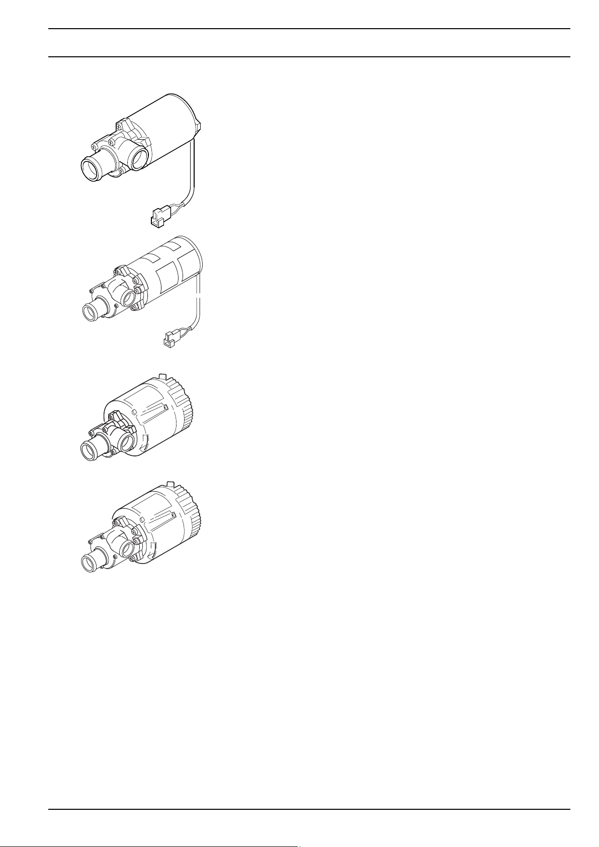
An external circulating pump is installed inside the vehicle,
or, in the case of compact units, directly at the heater.
11
4
3
2
1
6
10
7
8
9
Thermo 231/301
1 Burner
2 Coolant inlet
3 Temperature limiter
4 Temperature sensor
5 Coolant outlet
6 Heat exchanger
7 Exhaust outlet
8 Fuel return
9 Combustion air inlet
10 Fuel delivery
11 Splash protection cover
(instead of screen)
5
Thermo 231/301
201
2 General Description Thermo 230 / 231 / 300 / 301 / 350
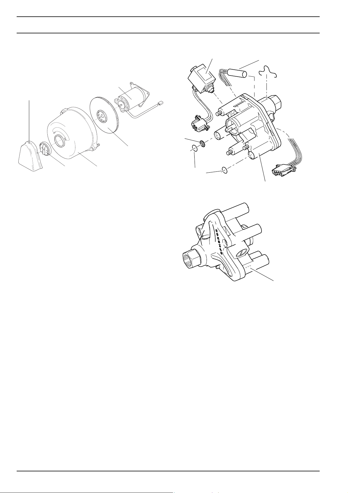
2.1 Combustion Air Fan
The combustion air fan supplies the air required for
combustion from the combustion air inlet to the combu
stion chamber.
Fan motor
Splash protection cover
Fan wheel
Screen
The fan consists of a fan motor with fan wheel. Air is taken
in through a splash protection cover or a screen and the
cap. The heaters Thermo 231 and 301 are provided with
a splash protection cover only.
Cap
-
Screen
O-ring
Solenoid valve
Nozzle block
pre-heater (optional)
Fuel Pump
2.2 Fuel Pump
The fuel pump is responsible for fuel supply.
The pump is driven by the burner motor via a coupling.
Fuel is compressed in the fuel pump to approx. 10 bar and
atomised via the atomiser nozzle.
The solenoid valve integrated into the fuel pump opens
and closes the fuel supply to the atomiser nozzle.
Three different fuel pumps are assigned to the different
heating capacity classes of the Thermo series.
These are identified by the heating capacity class specification as well as colour dots:
• 16 KW: 1 color dot
• 23-35 KW: 2 color dots
• 40 KW: 3 color dots
Color dots for
identification
of the heating
capacity class
The fuel pump can be used in dual-line operation (fuel
supply and return line).
If the heater is operated with
– a long fuel supply line
– check valves in the fuel supply and return line
– a fuel filter in the fuel supply line
– single-line operation
the fuel supply line must be filled prior to first heater
start-up.
202
Thermo 230 / 231 / 300 / 301 / 350 2 General Description
2.2.1 Nozzle block preheater
At extremely low temperatures malfunctions may occur
without a nozzle block preheater.
At a temperature of < 0°C a thermostat activates the
heater cartridge in the nozzle block. The heating period
depends on the heat reflected within the combustion
chamber. Preheating is deactivated when the thermostat
ambient temperature is +8°C.
If the heater is not equipped with a nozzle block preheater
a retrofit is possible.
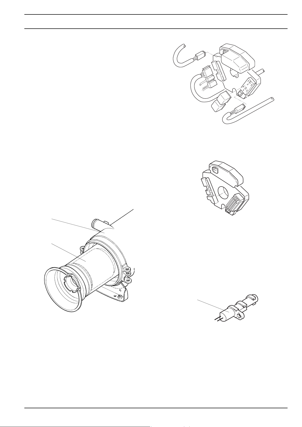
2.3 Heat Exchanger
IThe heat exchanger transfers the heat generated by
com-bustion to the coolant circuit.
2.4 Combustion Chamber
The fuel/air mix is dispersed in the combustion chamber
for combustion to heat the heat exchanger.
Heat exchanger
Combustion chamber
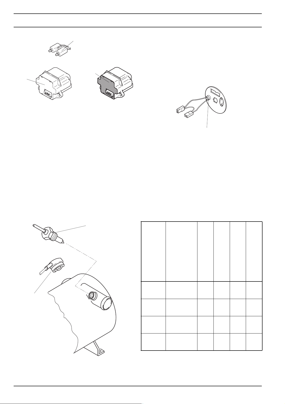
Control Unit 1572
Control Unit 1572D
2.6 Flame Sensor
The flame sensor continuously monitors the flame
condition during operation. The flame sensor is a photo
transistor changing its resistance depending on the flame
intensity. The signals are supplied to the control unit for
processing.
2.5 Control Unit
The control unit 1572 or 1572D is the central component
to ensure controlled operation and monitoring of
combustion. If the heater has a control unit 1572 installed,
a retrofit of control unit 1572D is possible (see Section 9).
Flame sensor
2.7 Igniter Box with Igniter Electrodes
The igniter box generates the high voltage for igniting the
fuel/air mix by a high voltage ignition spark across the
electrodes.
203
2 General Description Thermo 230 / 231 / 300 / 301 / 350
Igniter electrodes
Igniter box
(black connector
cover) only in
combination with
control unit
1572
Igniter box (green connector
cover; mechanically coded)
in combination with
control unit
1572D
and also
control
unit 1572
2.8 Temperature Sensor
The temperature sensor senses the coolant temperature
at the heat exchanger outlet as an electrical resistance.
This signal is supplied to the control unit for processing.
2.9 Temperature Limiter
The temperature limiter (bimetal) protects the heater
against undue high operating temperatures.
The temperature limiter can be reset manually.
The temperature limiter responds at a temperature in
excess of 125°C to switch off the heater.
In the case of Thermo 231 and 301 as well as the Rail
variant .126, the temperature limiter will trip at a
temperature in excess of 105°C.
After the temperature has dropped, an automatic reset will
occur.
Temperature sensor
2.10 Overheat Thermostat for burner
(Thermo 231 and 301 only)
The overheat thermostat is screwed onto the disk and
electrically connected to the solenoid valve of the fuel
pump. When the burner overheats the thermostat causes
an error lockout.
Overheat Thermostat
2.11 Circulation Pump
The externally mounted circulation pump ensures proper
coolant circulation in the vehicle and heater circuit.
Depending on the application, the circulating pump is
switched on via the control unit or directly via the vehicle
electrical system and operated during the entire heater
operation duration.
The heaters can be operated with the circulation pumps
Aquavent 5000 (U4814), Aquavent 5000S (U4854),
Aquavent 6000C (U4855) or Aquavent 6000SC (U4856).
Temperature
limiter
204
Circulating pump
U 4814
Aquavent
5000
U 4854
Aquavent
5000S
U 4855
Aquavent
6000C
U 4856
Aquavent
6000SC
(against 0,2 bar)
(against 0,2 bar)
(against 0,4 bar)
(against 0,4 bar)
Delivery rate
l/h V = V = W kg
5000
5000
6000
6000
Rated voltage
12
or
24
24 20…28 104 2,2
24 20…28 210 2,4
24 20…28 210 2,5
Operating voltage range
10…14
or
20…28
Rated power consumption
104 2,1
Weight
The circulating pump fuse may never be pulled, while the
pump is running, and may not be replaced, when the
pump is switched on.
Thermo 230 / 231 / 300 / 301 / 350 2 General Description
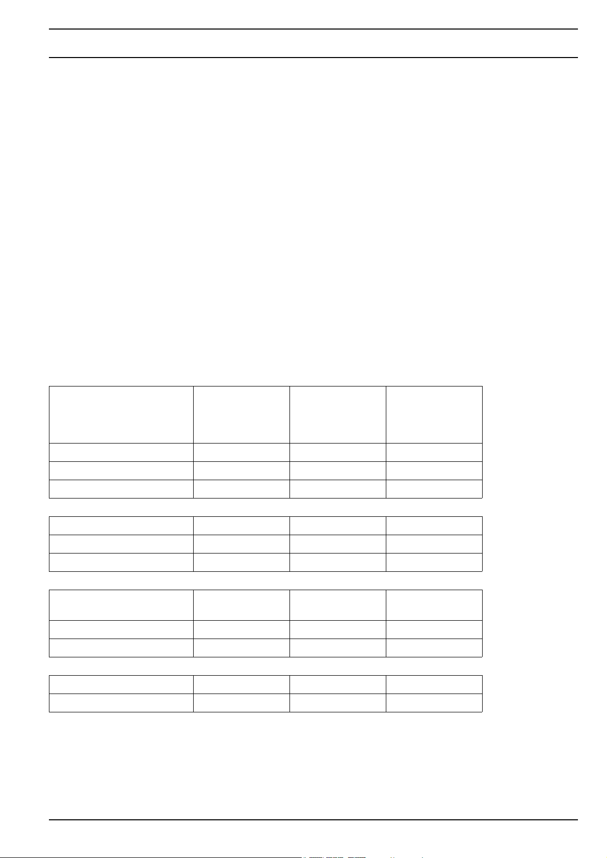
2.11.2 Aquavent 6000C (U4855) and Aquavent
6000SC (U4856) circulating pumps
The Aquavent 6000C (U4855) andAquavent 6000SC
Aquavent 5000
(U4814)
Aquavent 5000S
(U4854)
Aquavent 6000C
(U4855)
(U4856) circulating pumps are equipped with a brushless
motor.
NOTE
The Aquavent 6000C (U4855) has a floating-ring type
shaft seal.
The Aquavent 6000SC (U4856) is equipped wit a
magnetic coupling (no seal).
Soft start
The circulating pump motor starts slowly and gently. Max.
rotational speed is only reached after approx. 5 seconds.
Protection against dry running
Protection against dry running is integrated into the
circulating pump motor.
If the circulating pump motor consumes within a time
period of approx. 45 minutes significantly less current, dry
running is detected. The circulating pump motor is
switched off.
After approx. 2 minutes and circulating pump motor
reactivation, the operation can be continued.
Blocking protection
If the pump wheel is blocked, the motor will be switched
off via the error mode directly prior to standstill of the
pump wheel.
Aquavent 6000SC
(U4856)
2.11.1 Aquavent 5000 (U4814) and Aquavent
5000S (U4854) circulating pumps
The Aquavent 5000 (U4814) and 5000S (U4854) circulating pumps are equipped with a brush motor.
NOTE
Aquavent 5000 (U4814) with floating-ring type shaft seal.
Aquavent 5000S (U4854) uncoupled by a magnet (no
seal)
ATTENTION
The circulating pump motor is not equipped with an
internal inverse-polarity protection.
Overload protection
Overload protection is activated after the soft start is
completed. The current consumption will be limited.
In case of hydraulic overpressuring of the circulating
pump, the circulating pump motor will not be damaged.
Fehlermodus
In case of malfunctions the circulating pump motor is
switched off via the error mode. After approx. 5 seconds
the error mode switches the circulating pump motor into
energy-saving sleep mode.
Sleep mode
In sleep mode internal electronics consumers of the circulating pump motor are switched off.
Reactivation of the circulating pump motor
It is possible to reactivate the circulating pump motor from
sleep mode. For this purpose the power supply is
disconnected for > 2 min. After the power supply is
reconnected, the circulating pump motor restarts in softstart mode.
Inverse-polarity protection
The circulating pump motor is not equipped with an
internal inverse-polarity protection.
205

2 General Description Thermo 230 / 231 / 300 / 301 / 350
2.12 Fuel Filter
At compact devices of the series 230/300/350.126 and
.190 Rail an optional heatable fuel filter is provided, as an
additional option also for .124 and .155
If the electrical filter heating is hooked-up, the temperature
switch turns the integrated filter heating
on at ≤ 0,5 ± 2,5 °C and
off at ≥ 5,5 ± 2,5 °C fuel temperature.
Rail.
206
Thermo 230 / 231 / 300 / 301 / 350 3 Functional Description
3. Functional Description
Activation and deactivation is by means of a
• switch
•timer
• air conditioning
dependent on the type of installation.
For monitoring operation at least an operating indicator
light is provided.
Switch off releases a run-down procedure (see "Switch
off").
The heaters may be
• operated with power save for reduced fuel
consumption (see circuit diagram)
• equipped or retrofitted with a nozzle block preheater
for extreme low temperatures.
Heaters with control unit 1572D only
When connecting terminal +61 the heaters may operate in
the auxiliary heating mode of operation.
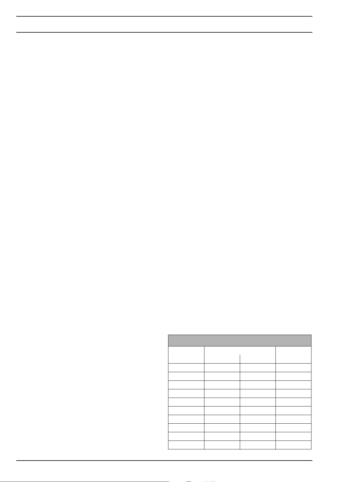
Switching thresholds
Control device Ident. No. 63482E
Ident. No. 97806B
Bus
Auxiliary heating
Upper operating point 85°C 85°C 85°C
Lower operating point 78°C 70°C 75°C
Parking heating
Upper operating point 85°C 80°C 85°C
Lower operating point 70°C 45°C 70°C
Parking heating (economic
setting)
Upper operating point 70°C 20°C 70°C
Lower operating point 55°C 75°C 55°C
Ident. No. 97810B
Rail
Standard
Ident. No. 63859D
Rail
J.E.S
Gradient evaluation Yes Yes Yes
Hysteresis adaption Yes Yes Yes
301
3 Functional Description Thermo 230 / 231 / 300 / 301 / 350
Switching thresholds for Thermo xxx Raill
230.040 230.056 300.124 xxx.126 300.155 350.190
Version Thermo xxx* 350.056 350.155
„VOSSLOH“„VOSSLOH
“
973 13A 90 162 37x 90 210 12B
Scope of delivery thru 90 162 36A
973 13D 90 162 35A
Heater
Control device 638 59D 679 81C 987 10x 978 04x
Auxiliary heating
Upper operating point 85°C 85°C 85°C 85°C
Lower operating point 75°C 72°C 70°C 70°C
Parking heating Preheating
Upper operating point 85°C 75°C 60°C 60°C
Lower operating point 70°C 60°C 45°C 45°C
Parking heating (economic
setting)
Upper operating point 70°C 57°C 20°C 40°C
Lower operating point 55°C 42°C 5°C 25°C
Gradient evaluation Yes Yes Yes
Hysteresis adaption Yes Yes Yes
Low voltage threshold 18,5V
* xxx means 230 or 300 or 350
3.1 Switch On
3.2 Heating Operation
keeping frost-free
(20 sec.)
Upon switch on the operating indicator light goes on.
Combustion air fan, fuel pump and circulation pump start
operation. (If fitted and temperature is < 0 °C nozzle block
preheater is also activated).
After approximately 12 seconds (run-up time) the high
voltage igniter spark is available. Approximately 1 second
later the solenoid valve in the fuel pump opens and the
nozzle sprays fuel into the combustion chamber to be
ignited by the igniter spark. A photo control circuit
deactivates the igniter box after flame-up.
302
After reaching operating temperature the control unit
takes over to provide controlled operation by activation
and deactivation of the burner in order to maintain a nearly
constant temperature of the heat exchanger (coolant).
The heating operation is terminated as soon as the upper
operating point is exceeded.
The heater now is in the control idle period. Heater
operation is resumed when the temperature drops below
the lower operating point.

Thermo 230 / 231 / 300 / 301 / 350 3 Functional Description
Heaters with control unit 1572D only
Gradient evaluation
In case of low coolant flow or poor coolant circuit venting
the temperature quickly increases in heating operation.
If gradient evaluation exists, the control unit recognises
the quick temperature increase and automatically sets the
upper switching threshold to a lower value. This prevents
residual heat triggering the overheating protection.
Control idle period
A rise in temperature above the upper switching point
makes the solenoid valve in the fuel pump shut off the fuel
supply initiating the run-down. The flame extinguishes,
the combustion air fan and the circulation pump however
continue their operation. After approximately 90 seconds
(120 seconds for heaters with control unit 1572D)
run-down is completed with deactivation of the
combustion air fan.
The circulation pump remains in operation during the
control idle period. The operating indicator light is on.
3.3 Switch Off
Switching off the heater stops combustion. The operating
indicator light goes out and run-down commences. The
combustion air fan and circulation pump are deactivated
after approximately 90 to 120 seconds (120 seconds for
heaters with control unit 1572D).
Reactivation of the heater during run-down is permitted.
The burner immediately resumes operation after the
run-up time.
burner after control idle period is raised above that for
normal operation and is automatically shifted up or down
dependent on the combustion time of the heater
(hysteresis adaptation).
Hysteresis adaptation (example)
After the first control idle period, the lower operating point
is 78°C.
Combustion operation is started when the temperature
falls below this threshold.
The length of combustion time until the upper operating
point is exceeded should be 120 seconds.
If combustion lasts more than 120 seconds, the lower
operating point is increased by 1 Kelvin, up to max. 80°C.
If combustion time is less than 120 seconds, the lower
operating point is lowered by 1 Kelvin, down to minimally
70°C.
3.6 Heater Lockout (heaters with control
unit 1572D only)
After the heater has performed eight start attempts due to
a malfunction or after five subsequent flame-outs the
heater enters a lockout and start attempts are suspended.
This lockout is superior to the normal error lockout.
Unlocking is performed by starting the heater and
disconnection of the main power supply of the heater
during error run-down.
3.7 Switch-off upon Failure (heaters with
control unit 1572)
3.4 Power Save
With power save on the control temperatures of the
heating circuit are kept low. Combustion performance is
not reduced.
This results in a reduced heat radiation loss when limited
heating performance is required (e.g. in heat hold opera
tion) cutting down fuel consumption.
3.5 Auxiliary Heating Operation (heaters
with control unit 1572D only)
When terminal +61 is connected and powered (engine is
running), the heater operates in the auxiliary heating
mode.
The power save mode is during auxiliary heating automatically deactivated by the control device.
The lower temperature threshold for reactivation of the
The heater switches off automatically when detecting one
of the following malfunctions.
The operating indicator light goes off. Combustion air fan
and circulation pump are deactivated after approximately
90 to 120 seconds.
-
Malfunctions during switch-on
– short or open circuit of temperature sensor.
– short or open circuit of flame sensor.
– open circuit of solenoid valve.
Malfunctions during start-up:
– flame detected by photo control circuit prior to high
voltage igniter spark.
– no flame detected after approximately 25 seconds
after heater start.
Malfunctions during heating operation:
– low voltage threshold of approximately 20V violated
for a duration of 12 seconds.
– no combustion for more than 10 seconds.
303

3 Functional Description Thermo 230 / 231 / 300 / 301 / 350
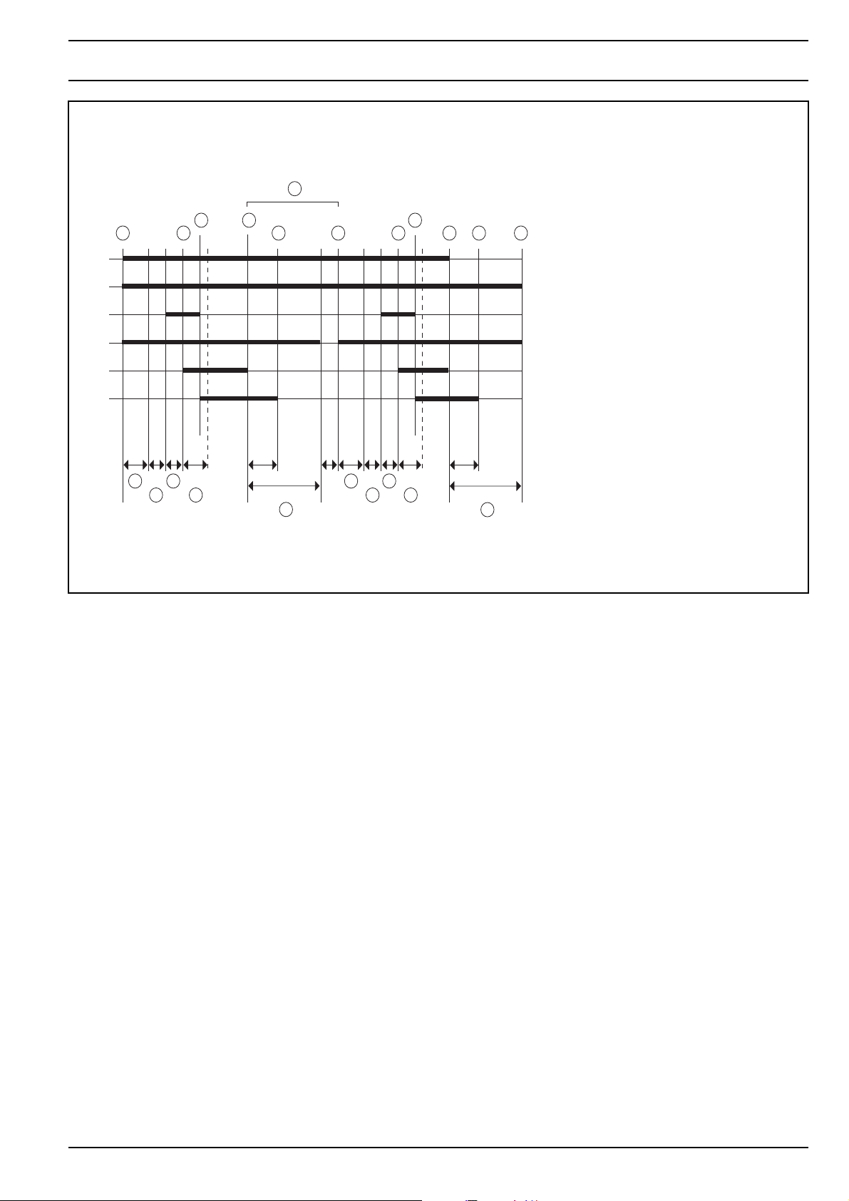
A H1 Operating indicator light
B E1 Heater cartridge
C M2 Circulation pump
D U1 Igniter box
E M1 Combustion air fan
10
F Y1 Solenoid valve
G B1 Flame sensor
1 Switch on
2 Start
3 Combustion operation
5 Temperature sensor – upper switching
threshold
6 Flame sensor – dark
7 Control idle
8 Temperature sensor – lower switching
threshold
9 Switch off
10 Heater – off
11 Nozzle block preheater
12 Start-up
13 Foreign light check
14 Pre-ignition
15 Safety period
16 Run-down
A
B
C
D
E
F
G
7
3
1
2
13 15 13 15
11
5
6
max.
8
16 12 14 161412
3
9
2
1s 12s12s 30s 90s1s12s
1s12s30s 90s1s
6
max.
Fig. 301:Functional sequence (heaters with control unit 1572)
– temperature sensor short circuit during control idle.
– temperature sensor open circuit during combustion.
– flame sensor short circuit during combustion.
– solenoid valve short circuit during combustion.
Malfunctions during run-down:
Detection of a flame after more than 30 seconds after start
of run-down with the circulation pump and combustion air
fan maintaining operation for the following 90 seconds.
Malfunctions by overheating:
Overheating results in deactivation of the heater by the
temperature limiter. After cool down of the unit and
correction of the fault the button of the temperature limiter
must be reset.
An error reset for a new start standby is achieved by
switching the heater off and on again.
304
Thermo 230 / 231 / 300 / 301 / 350 3 Functional Description
A H1 Operating indicator light
C M2 Circulation pump
D U1 Igniter box
E M1 Combustion air fan
F Y1 Solenoid valve
G B1 Flame sensor
10
1 Switch on
2 Start
3 Flame-up, combustion operation
5 Temperature sensor – upper switching
threshold
6 Flame sensor – dark
7 Control idle
8 Temperature sensor – lower switching
threshold
9 Switch off
10 Heater – off
12 Start-up
13 Foreign light check
14 Pre-ignition
15 Safety period
16 Run-down
A
C
D
E
F
G
7
3
1
2
max.
13 15 13 15
5
max.
6
max.
120s
16
8
3
2
max.
1s 12s12s1s12s
1s12s30s1s
12 141412
6
9
max.
30s
max.
120s
16
Fig. 302:Functional sequence (heaters with control unit 1572D)
3.8 Switch-off upon Failure (heaters with
control unit 1572D)
The heater switches off automatically when detecting one
of the following malfunctions.
Several subsequent switch-offs due to a malfunction will
cause the heater to enter an error lockout condition.
Flash pulses are output via the operating indicator light.
The combustion air fan and the circulation pump are
switched off after approx. 120 seconds.
Malfunctions during switch-on:
Short or open circuit of
– temperature sensor
– flame sensor
– burner motor
– solenoid valve
– igniter box
Malfunctions during start-up:
– short circuit of igniter box
– open circuit of igniter box
– flame detected by photo control circuit prior to high
voltage igniter spark.
– no flame detected after approximately 25 seconds
after heater start.
– short/open circuit or dry run (if programmed) of
circulation pump.
When using the circulation pump U 4851 approximately 15 seconds after switch-on the circulation
pump is automatically stopped and may only be
reactivated after approximately 2 minutes should
coolant be missing or the pump wheel be seized.
Malfunctions during heating operation:
– low voltage threshold of approximately 21V violated
for a duration of 20 seconds.
– no combustion for more than 10 seconds.
– temperature sensor short or open circuit.
– flame sensor short or open circuit.
– solenoid valve short or open circuit.
Malfunctions during heating operation:
(valid for application Thermo 350.190)
– low voltage threshold of approximately 18,5V violated
for a duration of 20 seconds.
– no combustion for more than 10 seconds.
– temperature sensor short or open circuit.
– flame sensor short or open circuit.
– solenoid valve short or open circuit.
305
3 Functional Description Thermo 230 / 231 / 300 / 301 / 350
Malfunctions during run-down:
Detection of a flame after more than 30 seconds after
start of run-down with the circulation pump and
combustion air fan only maintaining operation for the follo
wing 90 seconds.
Malfunctions by overheating:
Overheating results in deactivation of the heater by the
temperature limiter/thermostat. Dependent on heater
configuration:
– the reset button on the temperature limiter must be
reset.
– the reset of the thermostat is performed automatically
after cool down.
An error reset for a new start standby is achieved by
switching the heater off and on again.
Malfunctions by overheating of the burner
(Thermo 231 and 301):
Overheating of the burner causes the overheat thermostat
to initiate an error lockout at 150°C.
The solenoid valve closes, the fuel supply is cut off and a
run-down is launched. An auto-reset occurs after cooldown of the thermostat.
3.9 Error Code Output (heaters with
control unit 1572D)
When equipped with a standard timer an error code
readout appears on the display of the timer after a
malfunction.
NOTE
When the heater is operated by means of a switch the
type of error is output during heater run-down via a flash
code of the operating indicator light. After five short
signals the long flash pulses are counted. The flash
pulses correspond to the error number in the following
table:
F 01 no start
F 02 flame-out *
F 03 low voltage or excess voltage
F 04 foreign light detected during run-up and run-down
F 05 flame sensor defective
F 06 temperature sensor defective
F 07 solenoid valve defective
F 08 fan motor defective
F 09 circulation pump defective **
F 10 temperature limiter defective / overheating
F 11 igniter box defective
F 12 error lockout due to repeated malfunction or
repeated flame-out
(8x no start-up or 5x flame-out)
* A response of the overheat thermostat will be stored
in the control unit as a flame-out (F 02) (Thermo 231
and301).
** The error 09 is indicated only if the heater is equipped
with a circulation pump monitoring (see table below).
Table: Programmed SG1572D with integrated circulation
pump monitoring
EOL-Data record for SG 1572D
EOLData record
63317F
63860E
67980D X 67981D
96774B
97805C
97807C X 97810C
97809C X 97810C
97811B X 97812A
97813A
97815A
Circulation pump monitoring
Yes No
Ctr. device
programmed
306

Thermo 230 / 231 / 300 / 301 / 350 4 Technical Data
4. Technical Data
Where no threshold values are specified technical data
are understood to include standard tolerances for heater
units of ± 10% at ambient temperature of + 20 °C and at
nominal voltage.
Electrical components
Control unit, fan and circulation pump motors, solenoid
valve, igniter box, heater cartridge, nozzle block preheater
and timer are 24V components. Temperature limiter,
flame sensor, temperature sensor and switches are
voltage independent components.
NOTE
The allocation of circulation pumps to heater units must be
in accordance with coolant resistances.
Propellant
The suitable propellant is the Diesel fuel specified by the
vehicle manufacturer.
Only the type of fuel indicated on the identification plate
may be used. Also Diesel fuel with an addition of 5% PME
(vegetable oil methyl ester), class EL fuel oils (not fuel oil
L) or petroleum may be used if their quality is in accordance with the German standard.
A bad influence caused by additives is not known.
When using fuel out of the vehicle tank the information
about additives of the vehicle manufacturer must be observed.
When using fuel out of a separate fuel tank and at temperatures below 0°C, winter Diesel fuel must be used.
The use of flow improvers is permitted.
Mixing ratio for separate fuel tank and temperature below
0°C.
Temperature Winter Diesel
fuel
Additive petroleum or petrol
0 °C to –20 °C 100 % –
–20 °C to –30 °C 70 % 30 %
or special low temperature
Diesel fuel
–30 °C to –40 °C special low temperature
Diesel fuel or 100 % petroleum
401
4 Technical Data Thermo 230 / 231 / 300 / 301 / 350
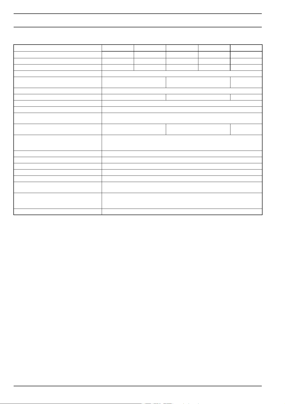
Heater Thermo 230 Thermo 231 Thermo 300 T hermo 301 Thermo 350
Type
Mark of conformity up to 4/03 ~ S230 ~ S327 ~ S229 ~ S328 ~ S228
EC type approval number e1*2001/56* 0007*-- 0010*-- 0008*-- 0011*-- 0009*--
Heater principle High pressure atomizer
Heating flow KW
Fuel Diesel / fuel oil
Fuel consumption kg/h 2.9 3.3 3.7
Nominal voltage V- 24
Operating voltage V- 20 ... 28
Operating voltage
(valid for application Thermo 350.190)
Nominal power consumption
(without circulation pump)
Permissible operating ambient
temperature range
(heater, control unit, circulation pump)
Permissible storage temperature °C +110 max.
Permissible operating overpressure bar 0.4 ... 2.0
Heat exchanger capacity l 1.8
Minimum capacity of circuit l 10.00
in exhaust at nominal voltage Vol.-% 10 ±0.5 related to 500 m above S.L.
CO
2
in exhaust at nominal voltage
CO
2
(valid for application Thermo 350.190)
Dimensions heater
(tolerance ± 3 mm)
Weight kg 19
(kcal/h)
Vol.-%
Thermo 230 Thermo 231 Thermo 300 T hermo 301 Thermo 350
23
(20 000)
V-
W
°C –40 ... +85
mm
mm
mm
65 110 140
19 ... 28
9,2 ... 10,1
length 610
width 246
heigh 220
30
(26 000)
35
(30 000)
402
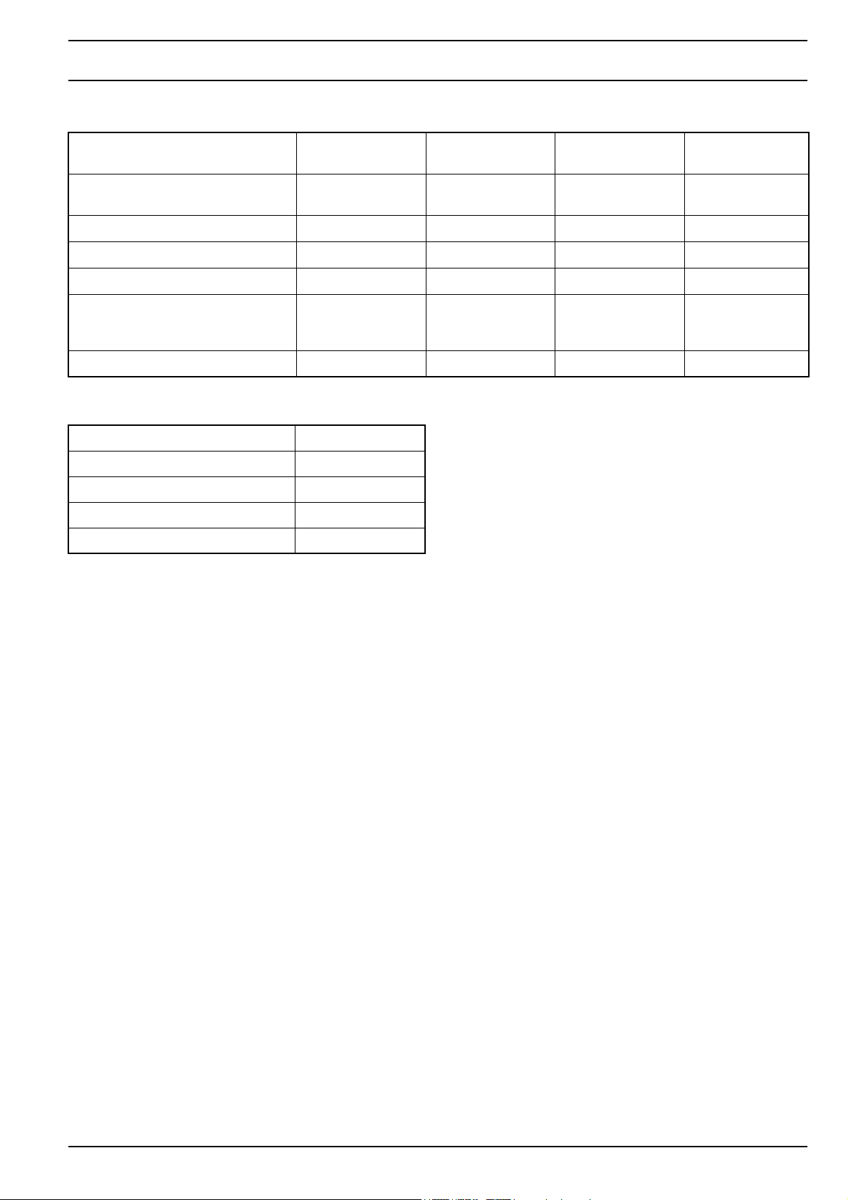
Thermo 230 / 231 / 300 / 301 / 350 4 Technical Data
Circulation pump U 4814
Aquavent 5000
Volume flow I/h 5000 (against 0,2
bar)
Nominal voltage V = 12 or 24 24 24 24
Operating voltage range V = 10...14 / 20...28 20...28 20...28 20...28
Nominal power consumption W 104 104 210 210
Dimensions Lenght 230
Width 100
Height 103
Weight kg 2,1 2,2 2,4 2,5
U 4854
Aquavent 5000S
5000 (against 0,2
bar)
Lenght 249
Width 100
Height 105
U 4855
Aquavent 6000C
6000 (against 0,4
bar)
Lenght 226
Width 115
Height 118
U4856
Aquavent 6000SC
6000 (against 0,4
bar)
Lenght 231
Width 115
Height 118
Optional Fuel Filter Heater
Filter Heater
Nominal power consumption W 240
Nominal voltage V - 24
Switch-on point C° 0,5 ± 2,5
Switch-off point C° 5,5 ± 2,5
403

4 Technical Data Thermo 230 / 231 / 300 / 301 / 350
404

Thermo 230 / 231 / 300 / 301 / 350 5 Troubleshooting
5 Troubleshooting
Troubleshooting is normally limited to the isolation of
defective components.
5.1 General
This section describes troubleshooting procedures for the
heaters Thermo 230, 231, 300, 301 and 350.
CAUTION
Troubleshooting requires profound knowledge about
components and their theory of operation and may only be
performed by trained personnel.
In case of doubt functional interrelations may be derived
from Sections 2 and 3.
Symptom Probable Cause
The following possible causes for trouble have not been
taken into consideration and must always be excluded
as a possible cause for malfunction:
corrosion on connector
loose contact on connector
wrong crimping on connector
corrosion on wiring and fuses
corrosion on battery terminals
After any fault correction a functional checkout in the
vehicle has to be performed.
5.2 General Fault Symptoms
The following table (Fig. 501) lists possible fault
symptoms of general nature.
CAUTION
Fault in electrical system
Operating indicator light is not on, no heater operation. • no power supply
• fuses
• wiring to terminals of connector A of control unit.
Fuse F2 blows. Short circuit in circulation pump or in wiring to heater.
Fuse F3 blows. Short circuit in wiring to heater/motor/nozzle block
preheater (if installed).
Normal heater operation, operating indicator light is out. Operating indicator light defective or wiring to light open
or shorted.
Fault in water system
Circulation pump not operating
(U 4851 and Aquavent 6000 S only)
• Failure mode activated
The failure mode switches the motor off in case of malfunctions. After approx. 5 sec the failure mode switches
the motor to the power saving sleep mode.
In the sleep mode the internal consumers of the motor
electronics are switched off. The power consumption in
this mode then amounts to < 2 mA.
The motor can be reactivated out of the sleep mode by
disconnection of the power supply for approx. 2 minutes.
After power reconnection the motor will again run up with
a soft start.
Fig. 501 General Fault Symptoms (Sheet 1 of 3)
501

5 Troubleshooting Thermo 230 / 231 / 300 / 301 / 350
Symptom Probable Cause
Heater operation stops because heat exchangers
connected do not dissipate enough heat.
Rate of flow too low, because
• air in heater, in heat exchangers or in system
sections.
• cocks (flow regulator) throttled, contaminated or
closed.
• contamination in system, e.g. in areas of restricted
flow.
• circulation pump rate of delivery insufficient (air in
pump housing).
wrong sense of rotation – check wiring colors
(black + / brown –).
• not enough anti-freeze.
• excessive system resistance (especially high when
cold).
• circulation pump defective.
Heat exchanger dissipate not enough heat,
because
• air in heat exchangers or in system sections.
• contaminated heat exchanger surfaces (external).
• insufficient air intake or exit.
• fan: rate of delivery low / wrong sense of rotation /
resistance too high.
• too much anti-freeze.
• heat exchanger of too low capacity.
Rough calculation of rate of flow
heat flow [kW] acc. to ident. label
Rate of flow in [l/h] = x 860
temperature difference ∆t in [K] or [°C]
measured between heater water inlet and outlet
(e.g. with contact thermometer)
Fault in fuel supply
No fuel delivery to heater. • fuel tank empty.
• kinked, closed, contaminated or leaking lines.
• paraffin deposits or water captured in fuel filter or fuel
lines.
• vent in tank clogged.
• fuel lines interchanged.
• fuel filter contaminated.
• fuel screen in pump contaminated.
Fig. 501 General Fault Symptoms (Sheet 2 of 3)
502

Thermo 230 / 231 / 300 / 301 / 350 5 Troubleshooting
Symptom Probable Cause
Wrong combustion
value cannot be set to rated value,
CO
2
combustion irregular.
Fig. 501 General Fault Symptoms (Sheet 3 of 3)
5.3 Fault Symptoms during Functional
Checkouts and Error Code Output or
Tests with Diagnostic Computer,
Components Tester or PC Heater
Diagnosis
5.3.1 General
Error Code Output
NOTE
Only heaters with a control unit 1572D provide an error
code output.
When equipped with a standard timer an error code
readout is available after a malfunction on the display of
the timer.
When the heater is operated by means of a switch a
coded flashing of the operating indicator light during
run-down of the heater or until switch-off indicates the
type of error (see 3.9).
• air bubbles in suction line (suction line leaking).
• fuel filter contaminated or leaking.
• fuel system integration leak (suction height, low
pressure in tank); observe installation instructions.
• fuel pump defective (pump pressure).
• return line throttled.
• filter screen in pump contaminated.
• O-ring sealing on fuel pump no longer effective
(ageing)
• nozzle jet defective.
• combustion air or exhaust lines throttled or closed.
• fan motor speed too low.
Operation of the diagnostic computer is menu controlled
by means of four push button switches.
For details refer to operating instructions for "Diagnostic
Computer".
Components Tester
NOTE
Checks with the components tester may only be
performed on heaters equipped with control unit 1572.
Using the components tester several types of faults and
component malfunctions may be analyzed in the vehicle.
The test of the individual components with the components tester is not intended. Faults like short or open
circuits may be detected with the components tester but
cannot be localized.
For details refer to operating instructions for "Components
Tester".
Diagnostic Computer
NOTE
Checks with the diagnostic computer may only be
performed on heaters equipped with control unit 1572.
By use of the diagnostic computer heaters may be
checked in the vehicle. The following tests are available:
• indication of measured values: water temperature,
control unit supply voltage, flame sensor bright/dark.
• indication and erasure of faults stored in the control
unit.
PC Heater Diagnosis
By use of the PC heater diagnosis heaters (with control
unit 1572 or 1572D) may be tested in the vehicle.
For details refer to operating instructions for "PC Heater
Diagnosis".
503
5 Troubleshooting Thermo 230 / 231 / 300 / 301 / 350
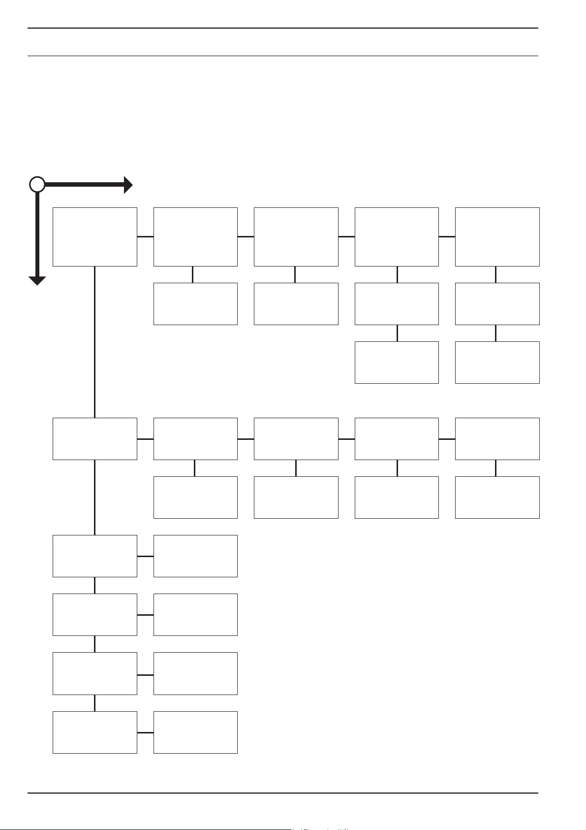
5.3.2 Fault Symptoms
5.3.2.1 Fault Symptom "No Start"
NOTE
Heaters with control unit 1572D:
If the heater performs 8 consecutive attempts to start due
NO
Switch on heater.
Is combustion air fan
operating?
YES
Motor and fan wheel
free to move?
Check motor electrics
and replace as
required.
Is fan wheel caught
in cap?
Replace cap
and fan wheel.
to a malfunction, the heater enters an error lockout and
stops any further attempts to start. This error lockout is
superior to the normal error lockout condition.
The error lockout reset is achieved by switching the heater
on and disconnection of the heater power supply during
run-down.
Is voltage present on
plug contact A3?
Is voltage too low?
Rated value >20,5 volts
(± 0,5 volts)
Low voltage switch
off during start-up.
Check battery.
Check fuses F1/F2/F3
and relais K1, K2 and
replace as required
(control unit 1572
only).
Does trouble persist?
Check electrical
wiring and
connections.
Does trouble persist?
Control unit defective,
replace.
Is fuel free of bubbles
in supply and return?
Is solenoid valve
connected to
electrics?
Is gap between igniter
electrodes ok?
Is nozzle free of foreign
matter and deposits
and properly secured?
Is fuel filter
contaminated?
Replace fuel filter. Retighten line
Connect solenoid
valve.
Check gap between
igniter electrodes.
Replace nozzle.
Fuel suction line
leak?
connections,
replace lines as
required.
Fuel lines empty? Are O-rings in fuel
Repeat start (several
times if necessary)
until lines are filled.
pump?
Is pump mounted
securely?
Fuel pump defective,
replace.
504
Is viewing glass of
flame sensor
contaminated?
Clean window and
viewing glass.
 Loading...