

Spheros NGW 300, GBW 300, LGW 300 Workshop Manual

Water heaters Workshop manual
NGW 300
LGW 300
GBW 300
NGW 300 / LGW 300 model
02/2006
Identification no. 27 101 03B

NGW 300 / LGW 300 / GBW 300 Table of contents
Table of contents
1 Introduction
1.1 Content and purpose ..............................................................................................101
1.2 Meaning of the headings in capitals .......................................................................101
1.3 Additional documentation to be used .....................................................................101
1.4 Safety information and regulations .........................................................................101
1.4.1 General safety regulations ........................................................................101
1.5 Legal installation regulations .................................................................................102
1.6 Suggestions for improvements and modifications ..................................................102
2 General description
2.1 Combustion air fan .................................................................................................202
2.2 Gas pressure regulator ...........................................................................................202
2.2.1 Heating the gas pressure regulator ...........................................................202
2.2.2 Delayed-action solenoid (only for the NGW 300) .....................................203
2.3 Heat exchanger ......................................................................................................203
2.4 Combustion chamber ............................................................................................203
2.5 Control unit .............................................................................................................203
2.6 Flame monitor electrode ........................................................................................203
2.7 Ignition spark generator with ignition electrodes ....................................................204
2.8 Vacuum switch .......................................................................................................204
2.9 Gas inlet nozzles ....................................................................................................204
2.10 Regulating thermostat ............................................................................................205
2.11 Temperature limiter ................................................................................................205
2.12 Circulating pump .....................................................................................................205
2.12.1 U 4851 and Aquavent 6000 S (U 4852) circulating pumps ......................205
3 Description of function
3.1 Switching on ...........................................................................................................301
3.2 Heating mode ..........................................................................................................301
3.3 Switching off ...........................................................................................................301
3.4 Fault lockout ...........................................................................................................301
3.4.1 Errors when switching on .........................................................................301
3.4.2 Errors during the starting process ............................................................301
3.4.3 Errors during the heating mode ................................................................301
3.4.4 Shutdown of the heater, if there is low voltage ...............................................302
3.4.5 Shutdown of the heater, if there is excessive voltage (not a fault lockout)) ......302
3.4.6 Fault lockout, if there is a flame, but the solenoid is deactivated ........................302
3.4.7 Errors due to overheating/disruption of the temperature limiter ...........................303
3.5 Removing the heater lock Heizgeräteverriegelung .................................................303
4 Technical data................................................................................................................. 401
I

Table of contents NGW 300 / LGW 300 / GBW 300
5 Troubleshooting and elimination of faults
5.1 General information ................................................................................................501
5.2 General fault symptoms ..........................................................................................501
6 Functional tests
6.1 General information ...............................................................................................601
6.2 Combustion test ......................................................................................................601
6.2.1 Test of the CO2content ............................................................................601
6.3 Tests of individual parts ..........................................................................................602
6.3.1 Test of the regulating thermostat .............................................................602
6.3.2 Test of the temperature limiter .................................................................602
6.3.3 Test of the ignition electrodes ..................................................................602
6.3.4 Test of the flame monitor electrode .........................................................602
6.3.5 Test of the ignition spark generator .........................................................603
6.3.6 Test of the burner motor ..........................................................................603
6.3.7 Test of the vacuum switch .......................................................................603
6.3.8 Test of the gas pressure regulator ...........................................................603
6.3.9 Test of the delayed-action solenoid in the gas intake pipe ......................604
7 Wiring diagrams
7.1 General information ................................................................................................701
8 Service work
8.1 General information ...............................................................................................801
8.2 Work on the heater .................................................................................................801
8.3 Work on the vehicle ................................................................................................801
8.4 Trial run of the heater ............................................................................................801
8.5 Maintenance work .................................................................................................801
8.5.1 Disassembly and mounting of the burner head
8.6 Visual inspections and installation regulations ......................................................802
8.6.1 Connection to the vehicle’s cooling system ..............................................802
8.6.2 Connection to the vehicle’s gas system ....................................................803
8.6.3 Combustion air supply .............................................................................803
8.6.4 Exhaust pipe .............................................................................................803
8.7 Disassembly and installation .................................................................................805
8.7.1 Heater: disassembly and installation ....................................................... 805
8.7.2 Replacing the temperature limiter .............................................................805
8.7.3 Replacing the regulating thermostat ........................................................805
8.7.4 Replacing the SG 1585 control unit ..........................................................805
8.7.5 Gas pressure regulator: Dismantling and installation ...............................805
8.8 Start-up ...................................................................................................................806
8.8.1 Ventilation of the coolant circuit ................................................................806
........................................802
II

NGW 300 / LGW 300 / GBW 300 Table of contents
9Repair
9.1 General information ...............................................................................................901
9.1.1 Measures for components when the system is disassembled ..................901
9.1.2 Implementation of modifications ...............................................................901
9.2 Disasssembly and reassembly ...............................................................................905
9.2.1 Replacing the temperature limiter ............................................................905
9.2.2 Replacing the regulating thermostat ........................................................905
9.2.3 Replacing the SG 1585 control unit .........................................................906
9.2.4 Replacing the ignition spark generator ....................................................906
9.2.5 Replacing the ignition electrodes .............................................................907
9.2.6 Replacing the flame monitor electrode ....................................................908
9.2.7 Replacing the burner ................................................................................908
9.2.8 Disassembly and reassemmbly of the burner head .................................908
9.2.9 Replacing the heat exchanger 911
9.2.10 Replacing the combustion chamber .........................................................911
9.2.11 Replacing the gas pressure regulator ......................................................912
9.2.12 Replacing the delayed-action solenoid in the gas intake line 912
10 Packaging/Storage/Shipping
10.1 General information ..............................................................................................1001
III

NGW 300 / LGW 300 / GBW 300 Table of figures
Table of figures
201 NGW 300 water heater................................................................................................201
301 Sequence of operation..................................................................................................302
501 General fault symptoms................................................................................................501
601 Setting the CO2-content................................................................................................601
602 Testing the electrode clearances..................................................................................602
603 Testing the CNG (NGW 300) gas pressure regulator...................................................604
604 Testing the LPG (LGW 300) gas pressure regulator ....................................................604
701 Basic wiring for the NGW 300 / LGW 300 / GBW 300 with switch ...............................702
702 Basic wiring for the NGW 300 / LGW 300 / GBW 300 with timer .................................703
703 System wiring for the GBW 300 - MAN ........................................................................704
704 System wiring for the GBW 300 - USA.........................................................................705
705 System wiring for the GBW 300 Standard....................................................................706
706 System wiring for the NGW IVECO ..............................................................................707
707 System wiring for the LGW / NGW 300 Standard and DC ...........................................708
708 System wiring for the NGW 300 EvoBus Citaro ...........................................................709
709 System wiring for the NGW 300 MAN ..........................................................................710
801 Disassembly and mounting of the burner head ............................................................802
802 Example of a heater installation in a bus......................................................................804
901 Replacing the SG 1578 control unit by the SG 1585....................................................902
902 U 4851 circulating pump...............................................................................................903
903 Aquavent 6000 S circulating pump...............................................................................904
904 Replacing the temperature limiter and regulating thermostat.......................................905
905 Replacing the SG 1585 control unit..............................................................................906
906 Replacing the ignition spark generator .........................................................................906
907 Replacing the ignition electrodes, the flame monitor electrode and the burner............907
908 Burner head: disassembly and reassembly.................................................................909
909 Replacing the heat exchanger and the combustion chamber.......................................911
910 Adapters .......................................................................................................................912
IV

NGW 300 / LGW 300 / GBW 300 1Introduction
1Introduction
1.1 Content and purpose
This workshop manual serves as support for trained staff
in the repair of the NGW 300, LGW 300 und GBW 300
water heaters.
The heaters may only be operated with the kind of gas
indicated on the model plate and and with the relevant
kind of electrical connection.
1.2 Meaning of the headings in capital
letters.
In this manual, the words CAUTION, ATTENTION and
PLEASE NOTE have the following meaning:
CAUTION
This heading is used, if a failure to follow instructions and
procedures accurately or to follow instructions and
procedures at all can lead to injuries or to fatal accidents.
ATTENTION
This heading is used, if a failure to follow instructions and
procedures accurately or to follow instructions and
procedures at all can lead to the damaging of components.
PLEASE NOTE
This heading is used, if attention should be drawn to a
specific feature.
1.3 Further documentation to be used
1.4.1 General safety regulations
"General model approvals " with an official test stamp have
been issued by the Kraftfahrt Bundesamt [Federal Bureau
of Motor Vehicles and Drivers] for the NGW 300, LGW 300
and GBW 300 water heaters in the area governed by the
StVZO [Road Traffic Licensing Regulation]:
~ S 291 for the NGW 300 heater
~ S 313 for the LGW 300 heater
~ S 330 for the GBW heater
and a model approval in accordance with EC Directives
72/245/EEC (EMC) with authorisation no:
e1*72/245*95/54*1260*xx
Liability claims can only be asserted, if the claimant can
prove adherence to the the maintenance and safety
instructions.
Failure to follow the installation instructions and the
directions they contain will result in the exclusion of
liability on the part of Spheros. The same shall also apply
for repairs which are not conducted by experts or for those
where original replacement parts are not used. This will
result in the revocation of the general model approval for
the heater and thus the general operating permit for the
motor vehicle as well.
CAUTION
• The heater may not be operated in enclosed spaces
(e.g. a garage or a workshop without an extraction
system) due to the danger of contamination and
suffocationr, and may not be operated with time
preselection.
This workshop manual contains all the necessary
information and instructions with respect to the repair of
the NGW 300, LGW 300 and GBW 300 water heaters.
The use of additional documentation can be required.
If necessary, installation and operating instructions can
also be used.
1.4 Safety information and regulations
Basically, general accident pevention provisions and the
valid industrial safety directions must be adhered to.
"General Safety Regulations" which exceed the
framework of these provisions are listed below. The
specific safety regulations which affect the present
manual are issued in the individual sections or procedures
with headings in capital letters.
• Due to the risk of explosion, the heater must be
switched off at petrol stations and fuelling tanks.
• Due to fire danger, the heater may not be operated in
the vicinity of combustible materials such as dry grass
and leaves, paper board, paper, etc.
ATTENTION
Where combustible vapours or dust can form (e.g. in
proximity to fuel, coal, sawdust and grain storage areas or
the like), the heater must be switched off.
The heaters must be operated only with the kind of gas
indicated on the model plate.
NGW 300 with CNG (natural gas)
LGW 300 with LPG (propane)
GBW 300 depending on the design with CNG
(natural gas) or LPG (propane)
The proportion of methane in the CNG (natural gas) must
amount to 95 % at least. If the proportion of methane is at
a still permissible 85-95 %, the CO
readjusted.
Withdrawal of gas in LPG (propane) sysrems must
happen in the gas phase.
value must be
2
101

1Introduction NGW 300 / LGW 300 / GBW 300
ATTENTION
The gas pressure regulator must be replaced after
4 years of operation, for safety reasons. Failure to do
so can lead to leakage and thus an escape of gas, due
to aging of the sealing elements.
PLEASE NOTE
Oil and condensate which have accumulated in the gas
pressure regulator must be drained out in accordance with
section 8.
CAUTION
As the combustion noise of the heater is barely audible,
special care must be taken when working in the vicinity of
the heater. In any event, the heater should be secured to
prevent its being switched on unintentionally.
When there is a rather sustained period of smoke
emission, unusual combustion noises or a smell of gas,
the heater must be put out of operation by removal of the
fuse and may only be put back into service after an
inspection by staff trained by Spheros.
In the area where the heater is the temperature may not
exceed 100 °C (storage temperature). If this temperature
is exceeded, permanent damage can be done to the
electronic system.
Checking the status of the coolant should be done in
accordance with the process described in documentation
provided by car manufacturers. The water in the heater’s
heating circuit must contain at least 20 % brand name
antifreeze solution. In the event of overheating, if pure
water is used, due to its lower boiling point, this can lead
to a partial loss of cool water. In this case, coolant must be
replenished.
Additives in the heating circuit should not adversely affect
metal, plastic or rubber and should not form deposits.
The opening pressure in a car’s cooling system (normally
indicated on the radiator cap) must be between 0.4 and
2 bar of the maximum allowable working pressure.
1.5 Legal regulations for installation
under the floor of the vehicle, into the vicinity of the side
boundary of the driver’s cab or of the vehicle. Exhaust
gas pipes must be laid in such a way as to preclude the
expectation of exhaust gas fumes penetrating into the
interior of the vehicle. The function of parts of the vehicle
which are important for its operation must not be curtailed.
Accumulation of condensate in the exhaust pipe
absolutely must be removed. If necessary, a condensate
drain hole may be drilled.
Combustion air intake and exhaust outlet:
The openings of the combustion air intake and the exhaust
outlet must be designed in such a way as to prevent a
sphere with a diameter of 16 mm from passing through.
The heater’s electrical lines and switching and control
units must be configured so that their flawless operation
cannot be restricted under normal conditions.
Installing the heater in the driver’s cabin or the
passsenger compartment of a bus is not permitted.
The heater is not approved for installation in motor
vehicles used for the transportation of hazardous
materials.
Gas pipes must be laid in compliance with the VdTÜV,
TRG, ECE-R110. ECE-R67 and DVGW [German
Technical and Scientific Association for Gas and Water]
guidelines.
Gas pipes must be designed in such a way that torsion of
the vehicle, engine vibrations and the like have no effect
on their durability. They must be protected from
mechanical damage.
Gas pipes in buses must not be installed in the passenger
compartment or the driver’s cab. Parts that convey gas
must be configured so that entrances and exits are not in
danger of being obstructed in the event of a fire.
A regular check of the parts which carry gas, must be
carried out annually. Leaky or damaged parts must be
replaced by original replacement parts.
The particular operating status of the heater (at least on or
off) must be easily recogniable.
PLEASE NOTE
These regulations are binding in the area subject to the
StVZO [Road Traffic Licensing Regulation] and should
also be observed in countries where there are no specific
provisions.
The installation of heaters must be performed in
accordance with installation instructions.
The year in which the heater was first put into operation
must be identified by the installer on its model plate by
striking out/removing the inapplicable years permanently.
The combustion air must not be taken from the interior of
the vehicle.
The opening of the exhaust pipe should be installed to
face upwards or to the side, or, if the exhaust pipe runs
102
NGW 300 / LGW 300 / GBW 300 2 General description
n
2 General description
The NGW 300, LGW 300 and GBW 300 water heaters
operate in conjunction with the on-board heating system
– to heat the passenger compartment
– to defrost the window panels and
– to heat the water-cooled engines
in busses.
Water heaters operate independently of the vehicle’s engine and are connected to the cooling system, the gas system and the electrical system of the vehicle.
Heater type:
NGW 300 for the CNG type of gas (natural gas)
LGW 300 for the LPG type of gas (propane)
GBW 300
NGW 300 version for the CNG type of gas (natural gas)
LGW 300 version for the LPG type of gas (propane)
The heater which is designed to work in accordance with
the heat exchange principle is controlled by the
regulating thermostat in intermittent operation
The heater basically consists of
– the burner head
– the heat exchanger and
– the combustion chamber zusammen
The following components are located in the heater:
– a control unit
– a flame monitor electrode
– an ignition spark generator with ignition electrodes
– a regulating thermostat
– a temperature limiter and
– a vacuum switch
imfor control and monitoring.
In addition, a circulating pump and a gas pressure regulator for the gas are installed in the vehicle to supply the heating system as well as a thermostat valve for heating the
gas pressure regulator. The NGW 300 also has a timedelayed solenoid installed in the heater’s gas suction hose.
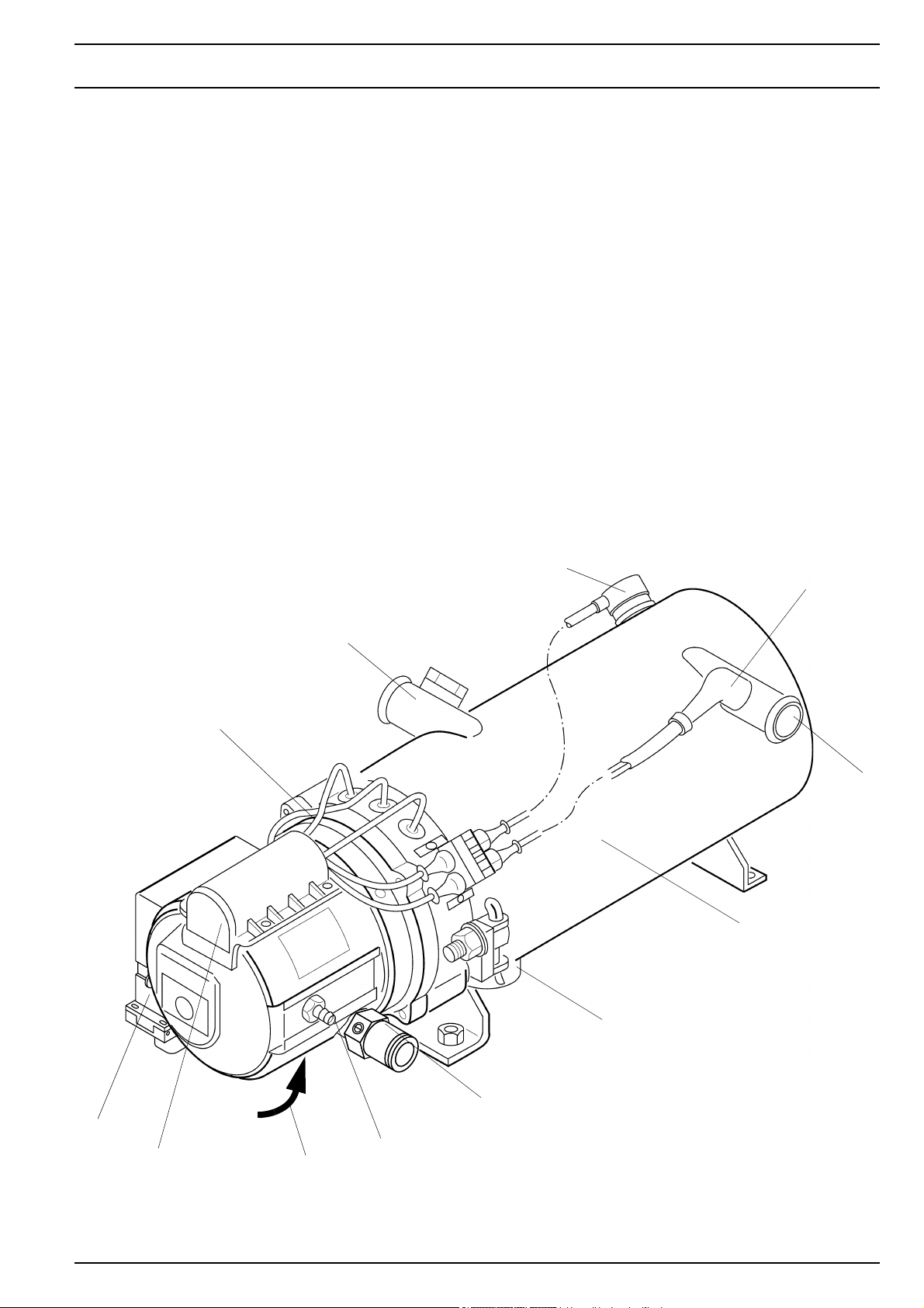
12
11
3
2
1
6
1 Burner head
2 Coolant inlet
3 Temperature limiter
7
4 Regulating thermostat
5 Coolant outlet
6 Heat exchanger
7 Exhaust fume outlet
8
9
10
Fig. 201 NGW 300 water heater
8 Gas inlet
9 Differential pressure connectio
10 Combustion air intake
11 Ignition spark generator
12 Control unit
4
5
201
2 General description NGW 300 / LGW 300 / GBW 300
2.1 Combustion air fan
The combustion air fan forces the air necessary for combustion from the combustion air inlet into the combustion
chamber. In addition, the necessary amount of gas is aspirated from the fan by means of the gas pressure regulator.
The fan comprises an impellent and a rotor which are joined together by means of a coupling. The air is sucked in
via a protective grille in the hood and mixed with gas in the
mixer.
There is a special version for a combustion air intake extension which commits the combustion air to be taken in
by means of this extension.
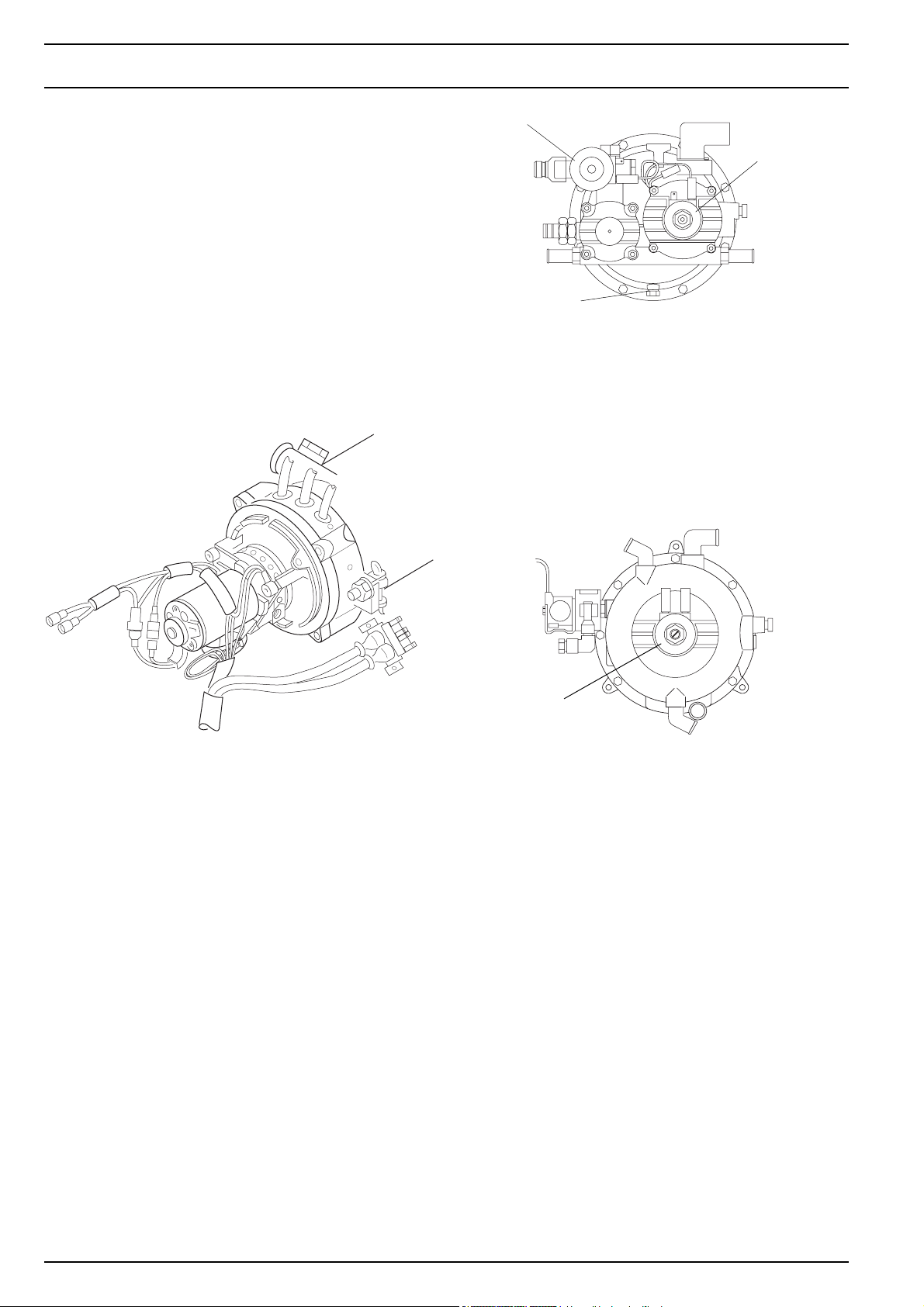
2
7
6
5
4
1 Gas outlet to the heater
2 Solenoid (2)
3 Water outlet
4 Drain plug (oil)
5 Water inlet
6 Safety valve
7 Gas inlet from the storage tank
CNG gas pressure regulator (NGW 300)
6
1
2
3
1
2.2 Gas pressure regulator
Gas is supplied by means of the vehicle’s gas supply system, in which the gas pressure regulator is incorporated.
Different types of regulators are utilised for operation with
CNG (natural gas) and LPG (propane).
In CNG gas pressure regulators, the gas pressure of the
system is regulated downward from a maximum of 220
bar of excess pressure in 3 steps to barely below atmospheric pressure. A safety valve protects the gas pressure regulator in the event of a pressure surge.
In LPG gas pressure regulators, the gas pressure of the
system is regulated downward from a maximum of 30 bar
of excess pressure in 2 steps to barely below atmospheric pressure.
After the solenoids have opened, the required quantity of
gas is sucked out of the gas pressure regulator by the
combustion air fan through the gas suction hose. The required quantity of gas is released by a diaphragm valve
in the gas pressure regulator. This is dependent on the
cross-section of the gas intake nozzle and the negative
pressure in the gas suction pipe.
4
5
4
2
3
1 Gas outlet to the heater
2 Drain plug (oil)
3 Water inlet
4 Solenoid (2)
5 Gas inlet from the storage tank
6 Water outlet
LPG gas pressure regulator (LGW 300)
2.2.1 Heating the gas pressure regulator
As the expansion of the compressed gas causes considerable cooling, the gas pressure regulator must be warmed up.
This is accomplished by integration into the cool water circuit. The flow rate is regulated by a thermostat valve.
At approximately 50 °C, the thermostat valve begins to restrict the flow rate and is in the final position at approximately 60°C. Further heating and regulation of the flow rate
are guaranteed by a leakage amount.
202
NGW 300 / LGW 300 / GBW 300 2 General description
2.5 Control unit
The control unit guarantees the function sequence and
monitoring of the firing operation.
The SG 1578 control unit for the NGW 300 and LGW 300
heaters is no longer available and is being replaced by the
modified SG 1585 control unit.
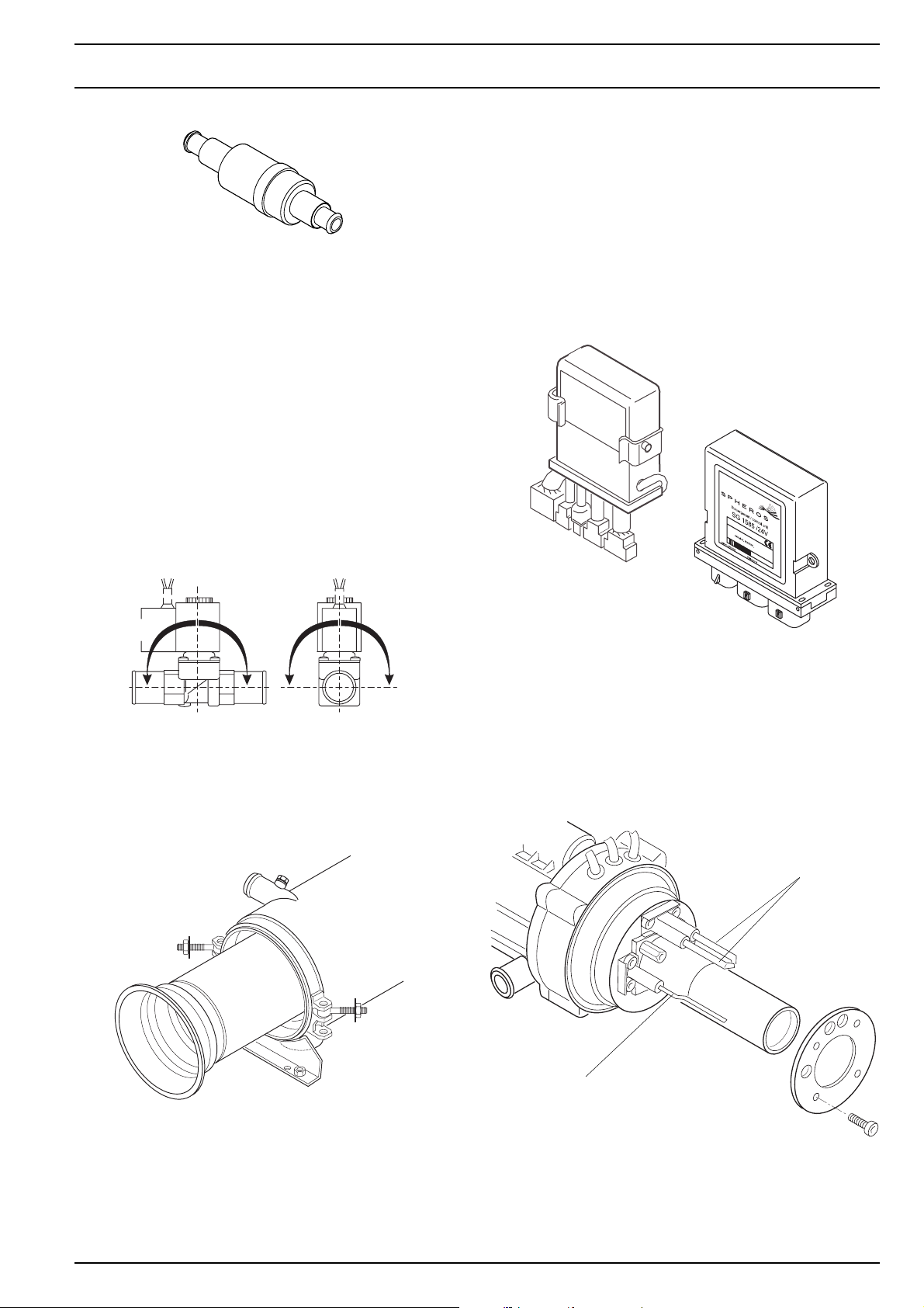
Thermostat valve
2.2.2 Delayed-action solenoid
(only for the NGW 300)
The delayed-action solenoid is necessary at gas supply
pressures of 8 bar for the safe functioning of the input solenoid valve on the gas pressure regulator.
The solenoid is installed in the gas hose from the gas pressure regulator to the heater and is connected electrically in
series to the solenoids in the gas pressure regulator.
After the solenoids in the gas pressure regulator are opened, the delayed-action solenoid releases the gas flow to
the heater with a second’s delay.
For higher gas supply pressures, the delayed-action solenoid can be installed as an additional safety element.
The delayed-action solenoid is a basic integral part of the
GBW 300, version NGW.
When refitting, the appropriate vehicle-specific adapter
wiring harness is required.
The GBW 300 heaters are already equipped with the SG
1585 control unit.
SG 1578
0-90°0-90° 0-90°0-90°
Delayed-action solenoid
2.3 Heat exchanger
In the heat exchanger, the heat produced by combustion
is transferred to the coolant circuit.
SG 1585
2.6 Flame monitor electrode
During the entire firing operation, the state of the flame is
monitored by the flame monitor electrode. By means of ionisation of the air, depending on the temperature (flame),
the signal is changed at the flame monitor electrode and
processed by the control unit.
Ignition
electrodes
2.4 Combustion chamber
The gas-air mixture is distributed in the combustion chamber and is burned there. The heat exchanger and the coolant flowing through it are heated by this process.
Flame monitor electrode
203
2 General description NGW 300 / LGW 300 / GBW 300
2.7 Ignition spark generator with ignition
electrodes
ImIn the ignition spark generator, high voltage is produced
to ignite the gas-air mixture.
Ignition occurs via a high voltage spark between the two
ignition electrodes.
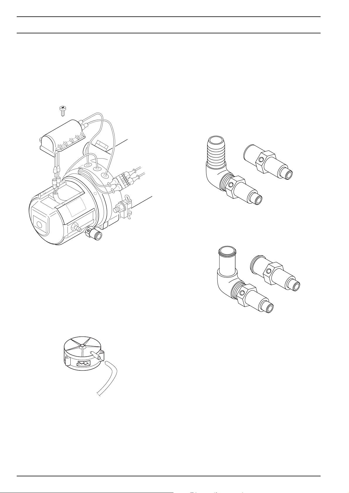
2.9 Gas inlet nozzles
The amount of gas required for combustion is determined
by the gas inlet nozzles on the burner.
The CO2 content in the exhaust gas can be set by means
of the setting screw.
Gas inlet nozzles are available in a straight form or an angular shape.
Gas inlet nozzles for NGW 300
2.8 Vacuum switch
The vacuum switch is mounted under the hood of the burner. It controls the negative pressure and thus the rotational speed of the combustion air blower. The signal is
processed by the control unit which then activates the solenoids on the gas pressure regulator.
When there is atmospheric pressure, the vacuum switch
is turned on. It is turned off by low pressure of from 2.5
±0.5 mbar.
Gas inlet nozzles for LGW 300
204

NGW 300 / LGW 300 / GBW 300 2 General description
2.10 Regulating thermostat
U 4814
The regulating thermostat (bimetal) measures the coolant
temperature at the water outlet of the heat exchanger. The
signal is conducted to the control unit and is processed
there.
The system is switched off at 75±3°C
and is switched on again at 68±5°C.
U 4851
2.11 Temperature limiter
The temperature limiter (bimetal) protects the heater
against incorrect high temperatures. The temperature limiter acts at a temperature above 125°C and switches off
the heater.
The temperature limiter may be reset mechanically, once
a temperature of 90 °C has been reached.
(U 4852)
Temperature limiter
Aquavent 6000 S
Regulating thermostat
2.12 Circulating pump
The circulating pump which is located externally guarantees that the coolant is conveyed in the vehicle’s or the
heater’s circuit.
The circulating pump is switched on by the control unit
and runs throughout the entire operation of the heater.
The heater can be operated with the U4814, the U4851 or
the Aquavent 6000 S (U 4852) circulating pump.
2.12.1 The U 4851 and Aquavent 6000 S
(U 4852) circulating pumps
The U 4851 / Aquavent 6000 S (U 4852) circulating pump
is equipped with a brushless motor.
Soft start
The motor starts slowly and protects its material from wear.
It reaches its maximum speed only after approx. 5 seconds.
Protection against dry running
A dry running protection system is integrated into the motor for speeds of 3,300 rpm.
If the motor consumes less than 4 A of current in a timeframe of 1018 revolutions, it detects that it is running dry.
The motor is switched off when it goes into error mode (after approx. 10 seconds of operation or approx. 15 seconds after being switched on.
For the Aquavent 6000 S circulating pump (U 4852) the
permitted dry running was extended to 45 minutes.
Blocking protection
If the operating speed falls below 57 rpm, the motor is
switched off by the error mode after approx. 1 second.
If the motor fails to complete a revolution in 1 second, despite having a current feed , it is switched off by the error
mode.
205

2 General description NGW 300 / LGW 300 / GBW 300
Overload protection
Overload protection is activated after completion of the
soft start. In this way, the consumption of current is restricted and the speed is regulated to 5,550 rpm. This means
that the motor will not be damaged, by the hydraulic compression of the circulating pump.
Error mode
The motor is switched off by the error mode in the event
of faults. After approx. 5 seconds, the motor will be switched from error mode into the power-saving sleep mode.
Sleep mode
In sleep mode, the internal users of the motor’s electronic
system are switched off. The consumption of current in
this mode then amounts to < 2 mA.
Reactivation of the motor
The motor can be reactivated from sleep mode. This is
done by disconnecting it from the power supply for approx. 2 minutes. After the voltage supply is restored, the
motor will restart in soft start.
Reverse polarity protection
The motor is not equipped with internal reverse polarity protection. The wiring harness in conjunction with
a15A fuse protect the motor against reverse polarity.
206

NGW 300 / LGW 300 / GBW 300 3 Description of function
3 Description of function
Depending on how it is equipped, the heater is turned on
and off by a switch, a timer or the airconditioning control
unit.
An operating indicator light is available to monitor the
opearting procedure.
After the heater is switched off ,there is an after-run.
(see 3.3 "Switching off".
NOTE.
Below is a description of of the operation cycle with the
SG 1585 control unit.
3.1 Switching on
When the heater is switched on, the operating indicator
lights up. The combustion air fan and the circulating pump
start.
The vacuum switch is shut off at the proper motor speed
(low pressure) and the signal is transferred to the control
unit and processed.
If the temperature falls to the lower switching point of the
regulating thermostat, the heater will be started again and
the after-run will be ended.
3.3 Switching off
When the heater is switched off, the solenoids in the gas
pressure regulator are closed and combustion ends. The
operating indicator light goes out and the after-run begins.
The combustion air fan and the circulating pump will be
switched off after approx. 125 seconds.
Switching the heater on again during the after-run is
permissible. It will restart only after the after-run has ended.
3.4 Fault lock-out
Upon detection of one of the fault characteristics listed
below, the heater performs a fault lock-out whereby the
operating indicator light goes out. The combustion air fan
and the circulating pump will be switched off after
125 seconds.
3.4.1 Faults when the heater is switched on
After approx. 15 seconds, the high voltage ignition spark
begins. If there is a shortlived drop in voltage when the
heater is switched on in the low voltage range, the lead
time is extended.
One second later, the solenoids open in the gas pressure
regulator (after another second, the delayed-action
solenoid in the gas hose for the NGW 300 opens, if
available) and the gas-air mixture is conveyed into the
burner by means of the combustion air fan, where it is
ignited by high voltage ignition sparks.
At the beginning of the flame monitoring, the ignition spark
generator is shut down so that flame detection is not
disrupted.
3.2 When the heater is in operation
Once the operating temperature has been reached, the
control unit takes over the regulated operation, whereby
the temperature of the heat exchanger (cooling liquid) is
maintained at a virtually constant level by alternately
switching it on and off.
If the temperature rises above the upper switching point
of the regulating thermostat, the solenoids in the gas
pressure regulator close off the gas supply and the afterrun is initiated.
The flame is extinguished, but the combustion air fan and
the circulating pump continue to run.
The circulating pump remains in operation during the
control pause; the operating indicator lights up.
– Interruption of the temperature limiter
– Short circuit of the vacuum switch
– Short circuit of the fan motor
– Short circuit of the circulating pump (when
programmed)
– Interruption of the circulating pump (when
programmed)
– Short circuit /interruption of the flame monitor mode
– Short circuit of the ignition spark generator
3.4.2 Faults during the starting process
– Intrerruption of the vacuum switch
– Interruption of the temperature limiter
– Solenoid valves don’t open
– Ignition spark generator defect
– Flame monitor electrode defect
– Flame detected in the supply line
– No flame detected after approx. 25 seconds
3.4.3 Faults while the heater is in operation
– Failure to reach the low voltage threshold of < 21.5 V
for a duration of 20 seconds
– Interruption of combustion for longer than 10 seconds
– Short circuit /interruption of the flame montor
electrode during combustion
– Interruption of the temperature limiter during
combustion
– Short circuit / interruption of the solenoid during
combustion
301

3 Description of function NGW 300 / LGW 300 / GBW 300
Operating indicator
Circulating pump
Ignition spark
generator
Combustion air fan
Solenoid
Vacuum switch
Flame monitor
CONTROL
Control pause 1
1 Main switch “ON”
2Start
3 Formation of flames
4 Upper switching threshold
5 Lower switching threshold
6 Switch off
7 Heater off
A Temperature monitoring
B Supply
C Extraneous light monitoring
D Preliminary ignition
E Flame ignition
F Flame stabilisation
G Firing operation
H After-run (control pause 1/
Fig. 301 Operating cycle
3.4.4 Shutdown of the heater when there is low
voltage
When there is low voltage of < 21.5 V, a fault lock-out and
an after-run occur. The heater is in a holding pattern
(control pause). If the voltage goes up again within 20
seconds to > 22.0 V, the heater starts anew.
3.4.5 Shutdown of the heater when theree is
low voltage (not a fault lock-out)
3.4.6 Fault lock-out when there is a flame but
the solenoids are deactivated
Upon detection of a flame when the solenoids have been
deactivated by the control unit, the heater is shut down
with an error.
In the error after-run , the fan motor is immediately shut
down, the circulating pump will continue to run until the
end of the error after-run.
If there is high voltage of more than 30 V for longer than
6 seconds, the users are shut down and the heater finds
itself in a holding pattern after the after-run.
If the voltage drops again to below 30 V, the heater will
switch itself on again.
302
– The operating indicator light blinks.
If there is a short circuit in the solenoids, with UB (terminal
30) the heater becomes locked.
The lock may be removed from the heater, only after the
cause of the fault has been removed. (see 3.5).
Where there are deactivated albeit permeable solenoids,
the heater will not be locked. After the cause of the fault
has been eliminated, the heater can be put into operation
once more by switching it on, off and on again,

NGW 300 / LGW 300 / GBW 300 3 Description of function
3.4.7 Faults due to overheating /interruption of
the temperature limiter
If the heater overheats there is a fault lock-out by means
of the temperature limiter and the heater becomes locked
after the error after-run.
After the system has cooled down and the cause has
been eliminated and the heater has been examined for
possible damage, in particular to the cabling, the
temperature limiter and the regulating thermostat, the
head of the temperature limiter must be reset manually.
Only then can the lock be removed from the heater.
3.5 Removing the heater lock
The heater lock must be removed as follows:
• By means of diagnosis: delete fault memory
or
• Switch on the heater; in the error after-run, remove the
heater from the power supply for 5 seconds (pull the
fuse). Restore the power supply and start the heater
again.
303

3 Description of function NGW 300 / LGW 300 / GBW 300
Blank page for notes
304
 Loading...