

Spheros DBW 230, DBW 160, DBW 300, DBW 2020, DBW 350 Workshop Manual
Water heaters Workshop Manual
DBW 160
DBW 230(2020)
DBW 300
DBW 350
Status: 07/2010
Visit www.butlertechnik.com for more technical information and downloads.
www.butlertechnik.com

Visit www.butlertechnik.com for more technical information and downloads.
www.butlertechnik.com
DBW 160 / 230 (2020) / 300 / 350 Contents
2
Contents
1 Introduction
1.1 Contents and purpose .......................................................................................................................... 101
1.2 Applicability of the manual.... ... ... ... ....................................................................................................... 101
1.3 Meaning of accentuations..................................................................................................................... 101
1.4 Further documentation to be used........................................................................................................ 101
1.5 Safety information and regulations....................................................................................................... 101
1.5.1 General safety regulations......................................................................................................... 101
1.6 Legal requirements regarding the installation.................... ... ... .... ... ... ... ................................................ 102
1.7 Suggestions for improvements and modifications ................................................................................ 103
2 General Description
2.1 Combustion air fan................................................................................................................................ 204
2.2 Motor..................................................................................................................................................... 204
2.3 Fuel pump............................................................................................................................................. 204
2.3.1 Nozzle-block preheater.............................................................................................................. 205
2.4 Heat exchanger .................................................................................................................................... 205
2.5 Combustion chamber............................................................................................................................ 206
2.6 Control unit ........................................................................................................................................... 206
2.7 Flame sensor........................................................................................................................................ 207
2.8 Electronic ignition unit with ignition electrodes ..................................................................................... 207
2.9 Temperature limiter /thermal fuse......................................................................................................... 208
2.10 Control thermostat................................................................................................................................ 208
2.11 Fan thermostat...................................................................................................................................... 209
2.12 Circulation pump................................................................................................................................... 209
3 Function Description
3.1 General................................................................................................................................................. 301
3.2 Operation.............................................................................................................................................. 301
3.2.1 Activation................................................................................................................................... 301
3.2.2 Heating operation...................................................................................................................... 301
3.2.3 Deactivation............................................................................................................................... 301
3.2.4 Malfunction cut-out................. ... ... ... ... .... ... ... ............................................................................. 301
4 Technical data
Electrical components..................................................................................................................................... 401
Fuel .............................................................................................................................................................. 401
Visit www.butlertechnik.com for more technical information and downloads.
www.butlertechnik.com
Contents DBW 160 / 230 (2020) / 300 / 350
3
5 Troubleshooting
5.1 General................................................................................................................................................ 501
5.2 General fault symptoms....................................................................................................................... 501
5.3 Troubleshooting – quick diagnostic...................................................................................................... 503
5.4 Fault symptoms........................ .... ........................................................................................................ 504
5.4.1 Heater does not start when being switched on......................................................................... 504
5.4.2 Heater repeatedly switches into malfunction mode approx. 30 s after bein g switched on ....... 505
5.4.3 Heater requires several attempts to start ................................................................................. 506
5.4.4 Heater turns off by itself during operation................................................................................. 506
5.4.5 Heater creates black smoke..................................................................................................... 507
5.4.6 Heater creates white smoke................................ ..................................................................... 508
5.4.7 Heater cannot be switched off.................................................................................................. 508
6 Function Checks
6.1 General................................................................................................................................................ 601
6.2 Settings................................................................................................................................................ 601
6.2.1 Adjusting CO
2
contents ............................................................................................................ 601
6.3 Checks of individual components ........................................................................................................ 602
6.3.1 Check of flame-sensor resistance ............................................................................................ 602
6.3.2 Check and adjustment of ignition electrodes............................................................................ 603
6.3.3 Check of electronic ignition unit................................................................................................ 603
6.3.4 Check of fuel pump................................................................................................................... 603
6.3.5 Check of burner motor.............................................................................................................. 604
6.3.6 Check of solenoid valve............................................................................................................ 604
6.3.7 Check of nozzle-block preheater.............................................................................................. 604
7 Wiring diagrams
7.1 General................................................................................................................................................ 701
8 Service and Maintenance
8.1 General................................................................................................................................................ 801
8.2 Heater servicing................................................................................................................................... 801
8.3 Vehicle servicing.......................................... ... ..................................................................................... 801
8.4 Heater test run..................................................................................................................................... 801
8.5 Maintenance work................................................................................................................................ 801
8.5.1 Swinging the burner head open and closed ............................................................................. 802
8.6 Visual inspections /
installation specifications 803
8.6.1 Connection to the vehicle's cooling system.............................................................................. 803
8.6.2 Connection to the vehicle's fuel system.................................................................................... 803
8.6.3 Combustion air supply.............................................................................................................. 805
8.6.4 Exhaust pipe............................................................................................................................. 805
Visit www.butlertechnik.com for more technical information and downloads.
www.butlertechnik.com

DBW 160 / 230 (2020) / 300 / 350 Contents
4
8.7 Removal and installation....................................................................................................................... 806
8.7.1 Heater, removal and installation................................................................................................ 806
8.7.2 Replacing the temperature limiter.............................................................................................. 806
8.7.3 Replacing the control thermostat............................................................................................... 806
8.7.4 Replacing the fan thermostat..................................................................................................... 806
8.7.5 Replacing the thermal fuse........................................................................................................ 806
8.7.6 Replacing the burner head........................................................................................................ 806
8.7.7 Replacing the electronic ignition unit......................................................................................... 806
8.7.8 Replacing the flame sensor....................................................................................................... 806
8.7.9 Replacing the combustion chamber.......................................................................................... 807
8.8 Start-up................................................................................................................................................. 808
8.8.1 Bleeding the coolant circuit........................................................................................................ 808
8.8.2 Bleeding the fuel-supply system................................................................................................ 808
9Repair
9.1 General................................................................................................................................................. 901
9.1.1 Measures on components in disassembled condition............................................................... 902
9.1.2 Carrying out modifications......................................................................................................... 902
9.2 Disassembly and assembly.................................................................................................................. 907
9.2.1 Replacing the temperature limiter.............................................................................................. 907
9.2.2 Replacing the control thermostat............................................................................................... 907
9.2.3 Replacing the fan thermostat..................................................................................................... 909
9.2.4 Replacing the thermal fuse........................................................................................................ 909
9.2.5 Replacing the control unit.......................................................................................................... 909
9.2.6 Replacing the burner head........................................................................................................ 909
9.2.7 Replacing the motor .................................................................................................................. 911
9.2.8 Replacing the high-pressure nozzle.......................................................................................... 912
9.2.9 Replacing the nozzle-block preheater....................................................................................... 912
9.2.10 Replacing the electronic ignition unit......................................................................................... 912
9.2.11 Replacing the flame sensor....................................................................................................... 912
9.2.12 Replacing the ignition electrodes............................................................................................... 912
9.2.13 Replacing the fuel pump............................................................................................................ 914
9.2.14 Replacing the solenoid valve..................................................................................................... 914
9.2.15 Replacing the combustion chamber.......................................................................................... 914
9.2.16 Thermostat of the nozzle-block preheater................................................................................. 914
9.2.17 Replacing the heat exchanger................................................................................................... 916
9.2.18 Replacing the nozzle block........................................................................................................ 917
9.2.19 Replacing the combustion air fan.............................................................................................. 917
10 Packaging / Storage and Shipping
10.1 General............................................................................................................................................... 1001
A Appendix
Regular maintenance of heater....................................................................................................................... A-2
Visit www.butlertechnik.com for more technical information and downloads.
www.butlertechnik.com
List of Figures DBW 160 / 230 (2020) / 300 / 350
5
List of Figures
301 Function sequence (heaters with control unit 1553)...................................................................................... 302
501 General fault symptoms ............................................... .................................................................................. 501
701 Au tomatic wiring diagram, DBW 160 with control unit 1553 and switch, system variants and pin allocation 702
702 Automatic wiring diagram, DBW 230/300 with control unit 1553, 24 volts..................................................... 704
703 Automatic wiring diagram, DBW 300/350 with control unit 1553, 24 volts..................................................... 706
704 Application ex ample for DBW 160/230/300, 12 and 24 volts, operation with timer and battery switch.......... 708
801 Swinging the burner head open and closed................................................................................................... 802
802 Example of heater installation in a bus .......................................................................................................... 804
901 Replacement of temperature limiter, control thermostat, fan thermostat and thermal fuse ........................... 908
902 Replacement of the control unit..................................................................................................................... 910
903 Replacement of the burner head.................................................................................................................... 910
904 Replacement of the motor.............................................................................................................................. 911
905 Replacement of nozzle block, nozzle-block preheater, high-pressure nozzle and flame sensor................... 913
906 Replacement of the thermostat of the nozzle-block preheater....................................................................... 915
907 Replacement of the solenoid valve................................................................................................................ 915
908 Replacement of the combustion chamber and the heat exchanger............................................................... 916
909 Replacement of the combustion air fan.......................................................................................................... 918
Visit www.butlertechnik.com for more technical information and downloads.
www.butlertechnik.com
DBW 160 / 230 (2020) / 300 / 350 1Introduction
101
1Introduction
1.1 Contents and purpose
This workshop manual serves to support trained personnel in the repair of coolant heaters DBW 160/230/300 /350.
The heater may only be operated with the specified fuel
(diesel) and only with the type of electrical connection
specified for the respective model.
1.2 Applicability of the manual
The manual is applicable for the heaters listed on the title
page. The heaters mainly differ with regard to their technical data (see Section 4).
1.3 Meaning of the warning and safety
notices
In this manual, the signal words DANGER, CAUTION and
NOTE have the following meanings:
DANGER
This heading is used when incorrect compliance or noncompliance with instructions or procedures may result in
injuries or lethal accidents.
CAUTION
This heading is used when incorrect compliance or non-
compliance with instructions or procedures may result in
damage to components.
NOTE
This headline is used to indicate particularly useful or
special information.
1.4 Further documentation to be used
This workshop manual contains all information and instructions required for the repair of coolant heaters DBW
160/230/300/350.
The use of additional documentation is normally not required.
If required, the installation instructions and the operating
instructions can be used in addition.
1.5 Safety information and
regulations
As a rule, the applicable general regulations and instructions concerning accident prevention and work safety
must be observed.
"General safety regulations" beyond the scope of these
regulations are listed in the following.
The special safety regulations of importance for this
manual are indicated in the relevant sections or process
descriptions in the form of signal words (warnings, cautions, notes).
1.5.1 General safety regulations
For the heaters DBW 160/230/300/350, type approvals
according to EC directives 72/245/EEC (EMC) and 2001/
56/EC (heater systems) have been granted, with the EC
approval number:
e1*2001/56*0006xx
For installation, primarily the provisions of Annex VII to di-
rective 2001/56/EC must be observed.
CAUTION
Non-compliance with the installation instructions and the
notes contained will lead to exclusion of liability by Spheros. The same applies to repairs not carried out by experts
or without the use of genuine spare parts. This will result
in the invalidation of the General Build-Type Approval of
the heater and hence the General Certification (German
'ABE').
The year the heater was initially commissioned must
be permanently marked on the type label
by removing the relevant year.
The heaters are approved for heating the vehicle engine
and the passenger compartment. When the heater is used
in vehicles not subject to the StVZO [German road-traffic
licensing regulations] (e.g. ships), locally applicable regulations must be complied with.
The heater may only be installed in vehicles or in independent heating systems with a minimum coolant volume
of 10 litres.
Visit www.butlertechnik.com for more technical information and downloads.
www.butlertechnik.com
1Introduction DBW 160 / 230 (2020) / 300 / 350
102
The heater may not be installed in the driver's or passenger's compartments of vehicles. If the heater is nevertheless installed in such a compartment, the installation case
must be tightly sealed towards the vehicle interior. From
the outside, the installation case must be sufficiently
vented so that a maximum temperature of 85 °C in the installation case is not exceeded. If this temperature is exceeded, malfunctions may occur.
DANGER
Because of danger of poisoning and suffocation, the
heater must not, not even with a timer, be operated in
enclosed rooms such as garages or workshops
without exhaust-gas extraction systems.
Because of explosion hazard, the heater must be
switched off at filling stations and filling systems.
CAUTION
Wherever flammable fumes or dust can form (e.g.
near fuel, carbon, wood-dust, cereal storage sites or
similar), the heater must be switched off due to explosion hazard.
The heater may not be operated in the vicinity of flammable materials, such as dry grass, leaves, cardboard
boxes, paper etc.
In the vicinity of the control unit, an ambient temperature
of 110°C (storage temperature) must not be exceeded
(e.g. when paint work is carried out on the vehicle).
If the specified temperature is exceeded, permanent
damage to the electronics may occur. When checking the
coolant level, proceed according to the vehicle manufac-
turer's instructions. The coolant in the heating circuit must
contain at least 10% of a brand-name anti-freeze agent.
Additives in the heating circuit may not be aggressive
against metals, plastics and rubber and may not cause
any deposits.
The opening pressure in the vehicle cooling syst em usually indicated on the radiator cap – must range
between 0.4 and 2.0 bar allowable working pressure (also
applies to separate heating circuits).
1.6 Legal requirements regarding the
installation
For installation, primarily the provisions of Annex VII to directive ECE R122 must be observed.
NOTE:
The provisions of these directives are binding in the
area of application of the ECE directive and should
also be observed in countries without specific regula-
tions!
(Excerpt from directive ECE R122, Appendix VII)
7.1 A clearly visible operation indicator in the operator's
field of vision must inform about the heater being switched
on or off.
Regulations regarding the installation in the vehicle
5.3.1 Area of application
5.3.1.1 As stipulated in Section 5.3.1.2, combustion
heaters must be installed according to the provisions of
Section 5.3.
5.3.1.2 In class-O vehicles with heaters for liquid fuel, it is
assumed that they comply with the pr ovisions of Section
5.3.
5.3.2 Positioning of the heater
5.3.2.1 Parts of the vehicle body and other components
in the vicinity of the heater must be protected from excessive heating and possible fuel or oil-induced soiling.
5.3.2.2 Even in the event of overheating, no fire hazard
may be caused by the combustion heater. This provision
is considered to be complied with if, during installation, relevant clearance to all components is maintained, sufficient ventilation is provided for or fire-resistant materials
or heat shields have been used.
5.3.2.3 In class-M2 and M3 vehicles, the combustion
burner may not be located in the passenger compartment.
Its installation in the passenger compartment is, however,
permissible when it is located in a properly se aled casing
which also complies with the provisions of Section 5.3.2.2.
5.3.2.4 The label named in Appendix 7, Section 1.4 or a
duplicate must be positioned to allow for easy reading
when the heater is installed in the vehicle.
5.3.2.5 The heater must be installed in a location where
the risk of injuring persons and damaging items carried is
as small as possible.
5.3.3 Fuel supply
5.3.3.1 The fuel-filler neck may not be located in the passenger compartment and must be equipped with a tigh tlysealing cap which prevents fuel from escaping.
5.3.3.2 In heaters for liquid fuel, where the fuel supply is
separated from the vehicle's fuel supply, the type of fuel
and the filler neck must be clearly marked.
5.3.3.3 On the filler neck, a note must be visible, saying
that the heater must be switched off before refuelling it. A
corresponding instruction must also be included in the
Visit www.butlertechnik.com for more technical information and downloads.
www.butlertechnik.com

DBW 160 / 230 (2020) / 300 / 350 1Introduction
103
manufacturer's operating manual.
5.3.4 Exhaust system
5.3.4.1 The exhaust outlet must be positioned so that no
exhaust fumes can get into the vehicle's interior via
venting devices, hot-air inlets or window openings.
5.3.5 Combustion air inlet
5.3.5.1 The air for the heater's combustion chamber must
not be drawn in from the vehicle's passenger compartment.
5.3.5.2 The air inlet must be protected and positioned in
a way that it cannot be blocked by garbage or luggage.
5.3.6 Heating air inlet
5.3.6.1 The combustion air supply may consist of ambient
air or circulating air and must be drawn in from a clean
area which can presumably not be contamina ted by
exhaust gas from the engine, the combustion heater or
another source in the vehicle.
5.3.6.2 The inlet opening must be protected by grilles or
other suitable means.
5.3.7 Heating air outlet
5.3.7.1 Hot air pipes in the vehicle must be protected and
positioned so touching them will not result in injuries or
damage.
5.3.7.2 The air outlet must be protected and positioned in
a way that it cannot be blocked by garbage or luggage.
5.3.8 Automatic control of the heating system
5.3.8.1 When the engine stalls, the heating system must
automatically be switched off and the fuel supply interrupt-
ed within five seconds. If a manually operated control
device has already been activated, the heating system
can remain in operation.
CAUTION:
Non-compliance with the installation instruction s and
the notes contained will lead to exclusion of liability
by Spheros. The same applies to repairs not carrie d
out by experts or without the use of original spare
parts. This results in the invalidation of the heater's
type approval and hence the ECE type approval.
Installation instructions for separate fuel tanks with regard
to the fuel supply of coolant heaters in vehicles:
• In busses, the installation in the passenger's or driv-
er's compartment is not permissible.
• In no vehicle may the fuel-filler neck be located in the
passenger's or driver's compartment.
• The fuel tanks must either be equipped with a vent ilat-
ed cap or any other type of ventilation (vent line).
Only caps in compliance with DIN 73400 may be used.
1.7 Suggestions for improvements and
modifications
Please address any complaints, improvements or suggestions for correction of this technical manual to:
Spheros GmbH
Friedrichshafener Straße 9 - 11
82205 Gilching
Phone: +49 (0) 8105 7721-201
Fax: +49 (0) 8105 7721-199
Visit www.butlertechnik.com for more technical information and downloads.
www.butlertechnik.com
1Introduction DBW 160 / 230 (2020) / 300 / 350
104
Notes
Visit www.butlertechnik.com for more technical information and downloads.
www.butlertechnik.com
DBW 160 / 230 (2020) / 300 / 350 2 General Description
201
2 General Description
The Spheros DBW 160, 230, 300 and 350 coolant heaters
supplement the vehicle's heating system
– to heat the passenger compartment
– to defrost the windows, and
– to preheat liquid-cooled engines.
The coolant heater functions independently of the vehicle
engine and is connected to the cooling system, fuel
system and electric system.
The heater is designed for heat transfer a nd is contr olled
by a temperature sensor. It's operation is intermittent.
The heaters of the type DBW 160, 230, 300 and 350 com-
prise the following main components:
– combustion air fan
– fuel pump
– heat exchanger
– combustion chamber
– electronic ignition unit with ignition electrodes
Some heater variants are equipped with a nozzle- blo ck
preheater.
The heater is controlled by
– a control unit
– a flame sensor
integrated in the device.
The control units are fitted laterally at the rear or on the
top, depending on the heater variant.
The heater may comprise
– a temperature limiter
– a thermal fuse
– a fan thermostat
depending on variant.
An external circulation pump is installed in the vehicle.
Visit www.butlertechnik.com for more technical information and downloads.
www.butlertechnik.com
2 General Description DBW 160 / 230 (2020) / 300 / 350
202
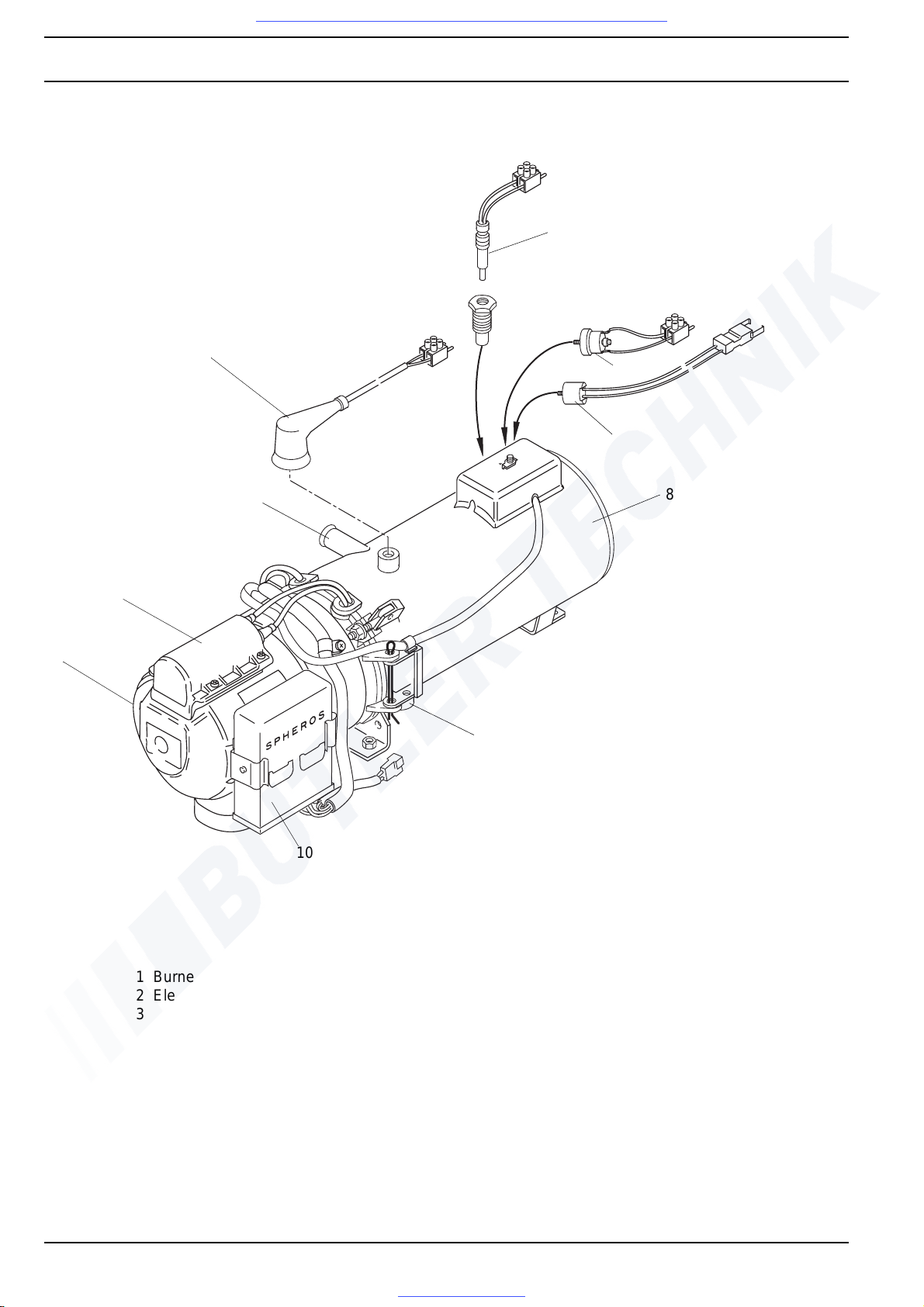
Heater DBW 160
1 Burner head
2 Electronic ignition unit
3 Coolant outlet
4 Control thermostat
5 Fusible link
6 Temperature limiter
7 Fan thermostat
8 Heat exchanger
9 Exhaust outlet
10 Control unit
8
7
6
4
3
2
1
9
10
5
Visit www.butlertechnik.com for more technical information and downloads.
www.butlertechnik.com

DBW 160 / 230 (2020) / 300 / 350 2 General Description
203
Heater DBW 230, DBW 300 and DBW 350
1 Burner head
2 Electronic ignition unit
3 Coolant inlet
4 Fusible link *
5 Control thermostat *
6 Temperature limiter *
7 Coolant outlet
8 Heat exchanger
9 Fuel return
10 Fuel supply
11 Exhaust outlet
12 Control unit
* for components installed in applicable
heater variants
3
2
1
4
5
6
8
7
9
10
12
11
Visit www.butlertechnik.com for more technical information and downloads.
www.butlertechnik.com

2 General Description DBW 160 / 230 (2020) / 300 / 350
204
2.1 Combustion air fan
The combustion air fan supplies the air required for combustion from the air intake into the combustion chamber.
Heaters are fitted with the following fan types:
DBW 160 – side-channel fan,
DBW 230 / 300 – radial fan,
DBW 350 – two-stage radial fan.
2.2 Motor
The motor drives the combustion air fan via a co up ling
and the fuel pump via a gearset.
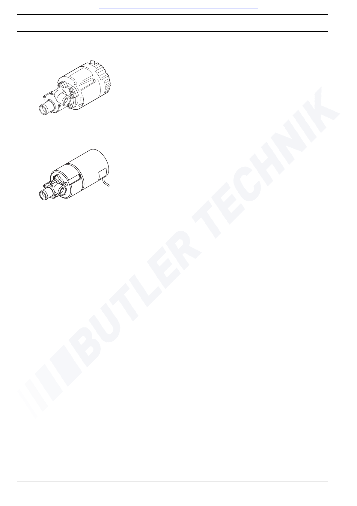
2.3 Fuel pump
The fuel pump supplies fuel for combustion. It is driven by
the combustion air fan motor via a coupling. Inside the fuel
pump, the fuel is pressurised to approx. 10 bar (DBW 160
11.5 bar) and is vaporised by the high-pressure atomiser.
Fuel supply to the atomiser is controlled by a solenoid
valve.
DBW 160
DBW
230 / 300
DBW 350
DBW
300.62
DBW 160 /
230 / 300 /
350
Visit www.butlertechnik.com for more technical information and downloads.
www.butlertechnik.com

DBW 160 / 230 (2020) / 300 / 350 2 General Description
205
2.3.1 Nozzle-block preheater
The nozzle-block preheater heats the fuel flowing to the
high-pressure nozzle.
Heaters without nozzle-block preheaters may show malfunctions at extremely low temperatures.
At temperatures < 0° C, the heating element in the nozzle
block is actuated via a thermostat.. Heating duration
depends on the heat reflected in the combustion chamber,
and the heater switches off when the thermostat reaches
a temperature of +8° C.
Heaters without nozzle-stock preheaters can be retrofitted.
For parts required please refer to parts list.
2.4 Heat exchanger
The heat exchanger transfers the heat generated by combustion into the cooling system.
DBW 160
Heating element
Nozzle block
Thermostat
DBW 230 /
300 / 350
Heating element
Nozzle block
Thermostat
DBW 160
to DBW
230(2020).32
to DBW
300.15
from DBW 230(2020).33
from DBW 300.15
from DBW 350.01
Visit www.butlertechnik.com for more technical information and downloads.
www.butlertechnik.com

2 General Description DBW 160 / 230 (2020) / 300 / 350
206
2.5 Combustion chamber
The fuel/air mixture is distributed in the combustion
chamber where it is burned, thus heating the he at
exchanger.
2.6 Control unit
The control unit is the core control element ensurin g th e
system function and the monitoring of the combustion.
Control unit 1553
DBW 160
to
DBW 300.15
from
DBW 230(2020).33
DBW 300.16
DBW 300.62 without flame pipe
DBW 350.01
to
DBW 230(2020).32
Visit www.butlertechnik.com for more technical information and downloads.
www.butlertechnik.com
DBW 160 / 230 (2020) / 300 / 350 2 General Description
207
2.7 Flame sensor
The flame sensor monitors the flame during the entire
combustion process. The flame sensor acts as a photoelectric resistor detecting the absence of a flame or as a
photoelectric transistor detecting the presence of a flame
and responding to its luminous intensity.
Its signals are received and processed by the control unit.
Flame sensor for control unit 1553
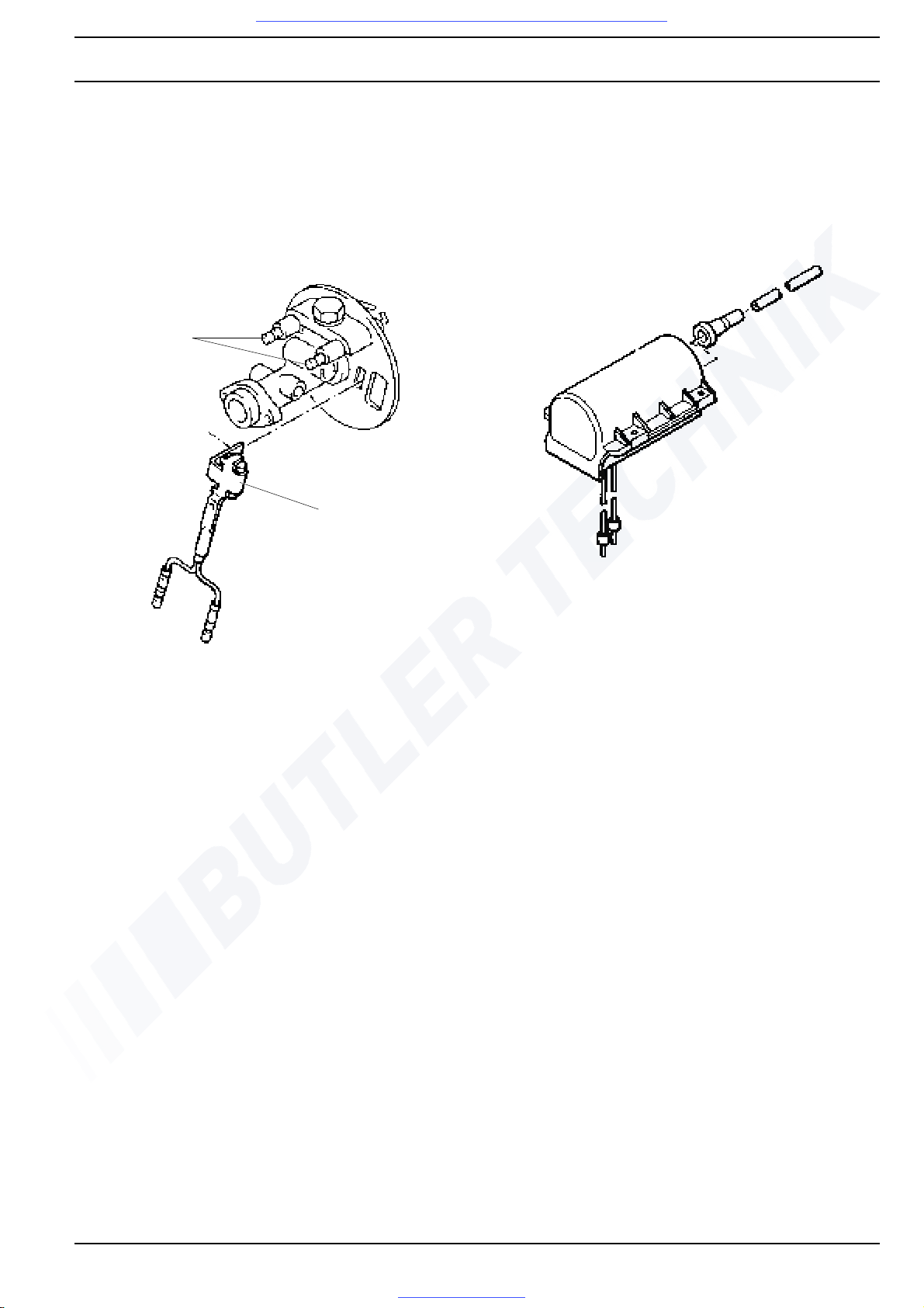
2.8 Electronic ignition unit with ignition
electrodes
The electronic ignition unit creates the high voltage
required to ignite the fuel/air mixture. Ignition is then realised by high-voltage spark-over between the two ignition
electrodes.
Ignition
electrodes
Flame sensor
Visit www.butlertechnik.com for more technical information and downloads.
www.butlertechnik.com
2 General Description DBW 160 / 230 (2020) / 300 / 350
208
2.9 Temperature limiter / Thermal fuse
Temperature limiter
The temperature limiter (bi-metal) protects the heater
against excessive operating temperatures. The temperature limiter trips when a temperature of 107° C or 117° C
is exceeded, turning off the heater. The temperature
limiter is resetable or self-resetting.
Thermal fuse
The thermal fuse protects the heater against excessive
operating temperatures. It comprises a fusible link that
trips at excessive temperatures, turning off the heater.
Heaters can be retrofitted with temperature limiters
replacing the thermal fuses.
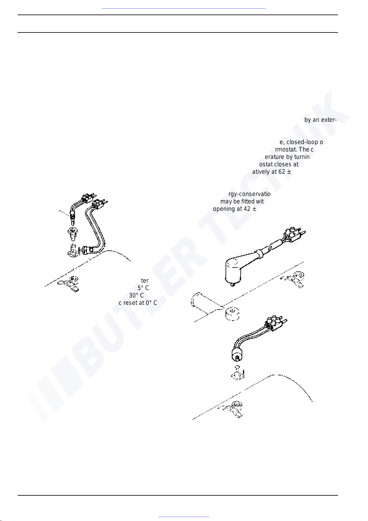
2.10 Control thermostat
Control thermostat at heater
After reaching operating temperature, closed-loop operation is performed by the control thermostat. The coolant is
maintained at a constant temperature by turning the
heater on and off. The thermostat closes at 63 ± 5° C and
opens at 70 ± 3° C.
External control thermostat
Closed-loop operation can also be executed by an exter-
nal control thermostat.
After reaching operating temperature, closed-loop operation is performed by the control thermostat. The coolant is
maintained at a constant temperature by turning the
heater on and off. The thermostat closes at 71 ± 2° C and
opens at 78 ± 2° C; alternatively at 62 ± 2° C and
70 ± 2° C.
Heaters with energy-conservation function (temperature
conservation) may be fitted with a thermostat closing at 35
± 2° C and opening at 42 ± 2° C.
Thermal
fuse
Reset
button
Temperature limiter
opens at 107 ± 5° C
resetable at 30° C
automatic reset at 0° C
DBW 160
DBW 230 / 300 / 350
Control thermostat at heater
Visit www.butlertechnik.com for more technical information and downloads.
www.butlertechnik.com
DBW 160 / 230 (2020) / 300 / 350 2 General Description
209
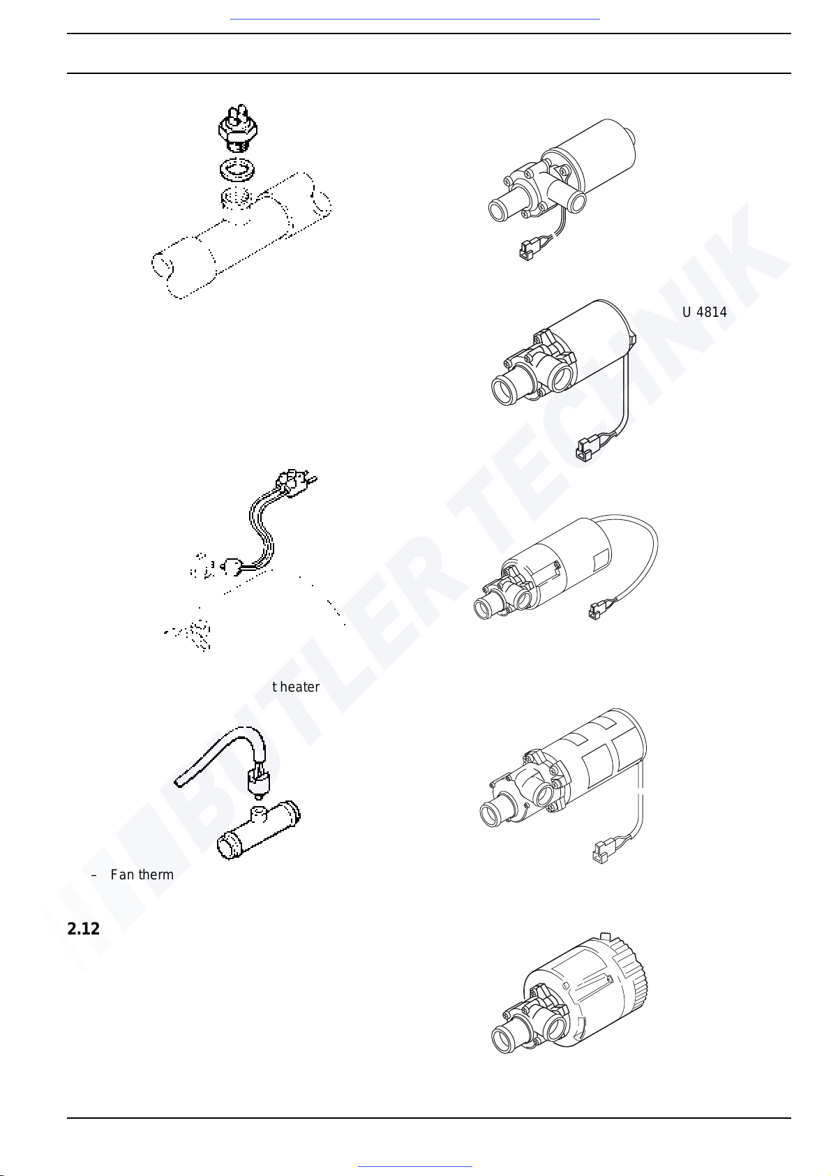
2.11 Fan thermostat
The fan thermostat turns the vehicle heater's fan on and
off at coolant temperatures between 30° C and 40° C. The
thermostat closes at 40 ± 3° C and opens at 30 ± 5° C.
Fan thermostat at heater
– Fan thermostat in coolant system
2.12 Circulation pump
The external circulation pump circulates the coolant in the
cooling system of the vehicle and in the heater. The pump
is activated by the control unit and runs througho ut the
entire operating period of the heater. Heaters are compatible with pumps of the type U 4810 (DBW 160 only),
U 4814, U 4851, U 4854, U 4855 or U 4856.
External control thermostat
U 4810
Recommended
for heater DBW
160
U 4814
Recommended
for heater DBW
230, 300 and
350
U 4851
Recommended
for heater DBW
230, 300 and 350
U 4854
Recommended
for heater DBW
230, 300 and
350
U 4855
(replaces
U 4851)
Recommended
for heater DBW
230, 300 and
350
Visit www.butlertechnik.com for more technical information and downloads.
www.butlertechnik.com
2 General Description DBW 160 / 230 (2020) / 300 / 350
210
U 4856
(replaces
U 4852)
Recommended
for heater DBW
230, 300 and 350
U 4852
Recommended
for heater DBW
230, 300 and 350
Visit www.butlertechnik.com for more technical information and downloads.
www.butlertechnik.com

DBW 160 / 230 (2020) / 300 / 350 3 Function Description
301
3 Function Description
3.1 General
The heaters are equipped with burners using high-pressure atomisers and run in intermittent operation. They are
thermostatically controlled (control unit 1553).
3.2 Operation
The heater is switched on and off at the
– switch (On/Off) or
– by the timer.
Its operating mode is shown by an operation indicator in-
tegrated in the timer or by a separate indicator light.
Heaters can be fitted with optional nozzle-block pre-
heaters and heater elements for operatio n at extremely
low temperatures.
Operation (see Fig. 301)
3.2.1 Switch on
When the system is switched on, the operation indicator
lights up. Combustion air fan, fuel pump and circ ulation
pump start. After approx. 15 seconds, the solenoid valve
opens and fuel is injected into the combustion chamber
via the atomiser. At the same time, a high-voltage ignition
spark is generated. When the flame sensor detects a
flame, it outputs a signal to the control unit which switches
the electronic ignition unit off.
If no flame is detected, please refer to 3.2.4.
3.2.2 Heating operation
After reaching operating temperature, closed-loop operation is performed by the control thermostat.
Coolant temperature is then maintained at a constant
level by switching the heater on and off. When the temperature exceeds the upper switch point, the solenoid valve
shuts of the fuel supply, causing the flame to extinguish.
The combustion air fan then runs on for approx. 150 seconds, switching off automatically. The circulation pump
keeps on running during the burner's off-periods, and the
operation indicator remains on. When the temperature
falls below the lower switch point, the heater is restarted.
3.2.3 Switch off
When the heater is switched off, combustion is stopped.
The operation indicator is turned off, and the purge cycle
begins. Combustion air fan and circulation pump are
switched off after approx. 150 seconds.
The heater cannot be restarted during purge cycle.
3.2.4 Malfunction cut-out
Heaters with control unit 1553
A malfunction cut-out occurs
– if no combustion is detected within approx. 30
seconds after the heater is switched on,
– if the fuel supply is interrupted for more than 10
seconds during heating operation,
– if thermal fuse or temperature limiter detect over-
heating of the heater. The thermal fuse must always
be replaced by a fuse of the identical type (observe
colour code). Reset the button of the temperature
limiter (once the heater has cooled down to below
60° C).
– if undervoltage is detected approx. 10 – 25 seconds
after the temperature falls below the switch point.
Once the cause of the malfunction has been eliminated,
the heater can be unlocked by switching it off and back on.
Visit www.butlertechnik.com for more technical information and downloads.
www.butlertechnik.com
3 Function Description DBW 160 / 230 (2020) / 300 / 350
302
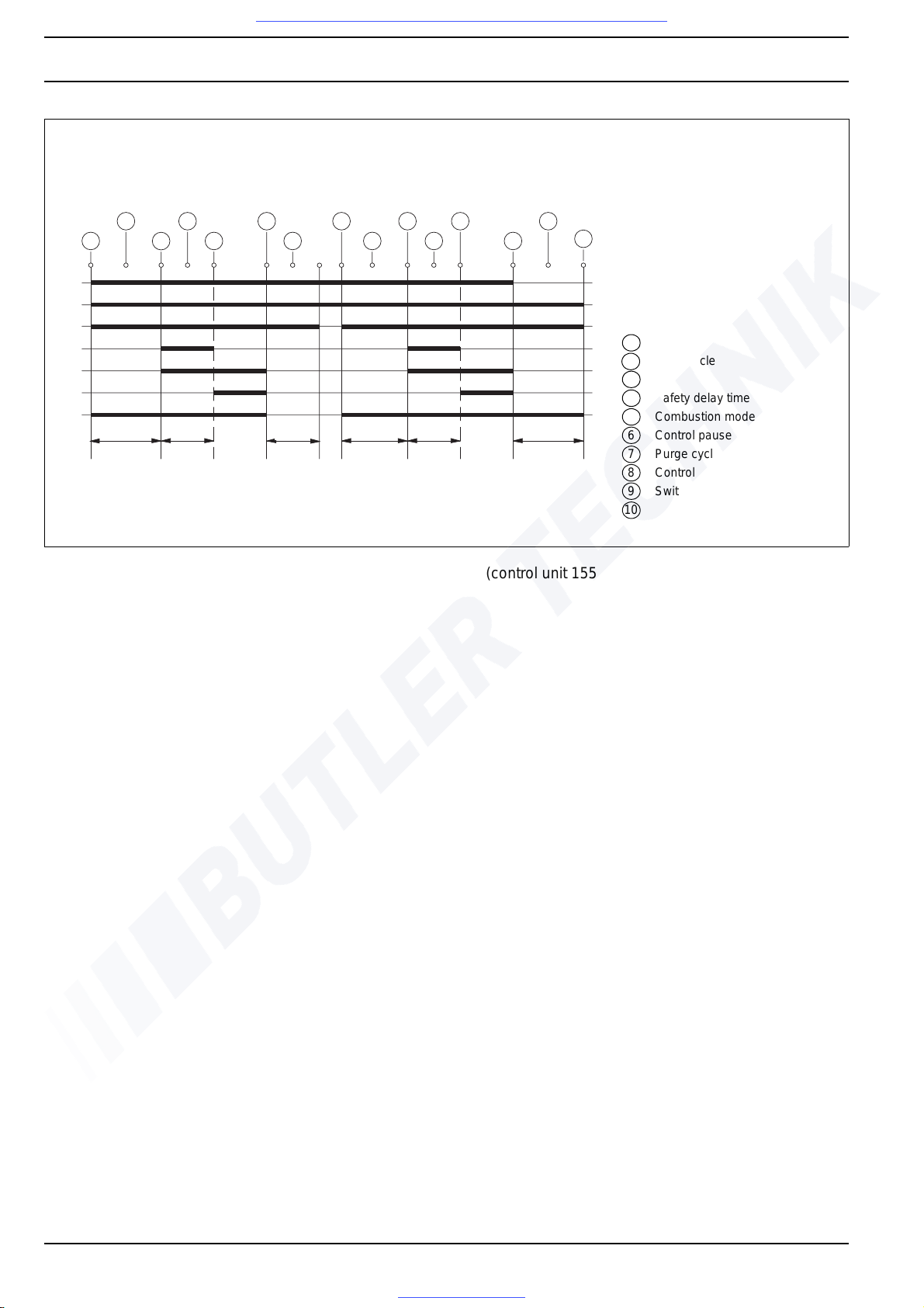
Fig. 301 Function sequence (control unit 1553)
1
10
3
5
82 4 6
7
3
2 4
5 7
9
10-25 s 5-25 s
ca.150 s
10-25 s
5-25 s
ca.150 s
A
B
C
D
E
F
G
A Operation indicator
B Circulation pump
C Combustion air fan
D Electronic ignition unit
E Solenoid valve
F Flame sensor
G Control thermostat
1 Activation
2 Initial cycle
3 Start
4 Safety delay time
5 Combustion mode
6 Control pause starts
7 Purge cycle
8 Control pause ends
9 Switch-off
10 Heater stops
Visit www.butlertechnik.com for more technical information and downloads.
www.butlertechnik.com
DBW 160 / 230 (2020) / 300 / 350 4 Technical Data
401
4 Technical data
Where no limit values are specified, technical data are understood to include standard tolerances for heaters of
±10% at an ambient temperature of +20° C and at nominal
voltage.
Electrical components
Control unit, motors for combustion air fan and circulation
pump, solenoid valve, electronic ignition unit, heating element, nozzle-block preheater and timer are designed for
24 volts. The components temperature limiter, flame
sensor, temperature sensor and switch are voltage-independent.
NOTE
Combinations of circulation pumps and heaters must be
selected in accordance with coolant flow resistance
Fuel
Only the type of fuel indicated on the heater's type label
may be used.
Commercially available diesel fuels in accordance with
DIN EN 590 (diesel fuel) may be used.
According to the diesel-fuel standard DIN EN 590, up to
5% of biodiesel additive is also permissible.
At temperatures below 0°C, a commercially available
winter diesel fuel should be used.
The use of flow improvers or additives is permissible.
Adverse effects are not known.
CAUTION:
For fuel taken from the vehicle tank, the vehicle manufacturer's specifications regarding additives apply.
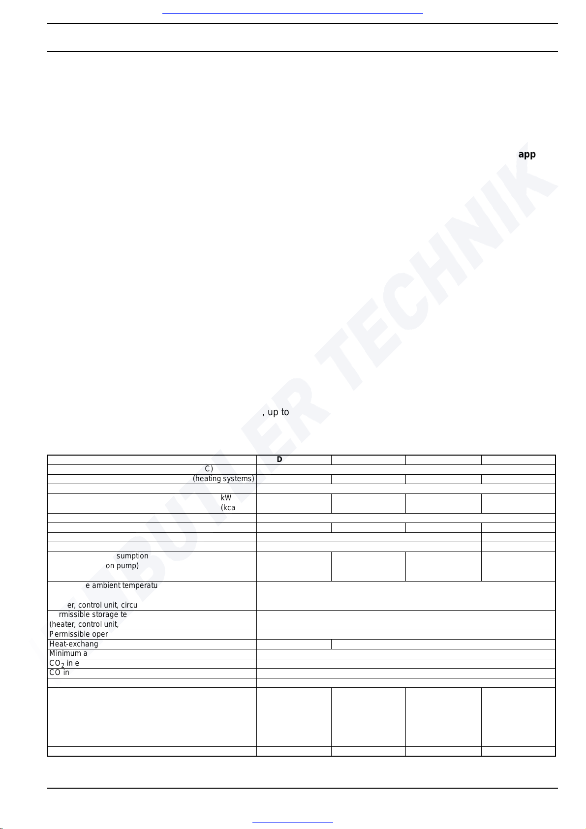
Heater DBW 160 DBW 230 DBW 300 DBW 350
ECE approval number according to R10 (EMC) 025038
ECE approval number according to R122 (heating systems) 000204 000205 000206 000207
Build type High-pressure atomiser
Heat flow kW
(kcal/h)
16
(13 800)
23.3
(20 000)
30
(26 000)
35
(30 000)
Fuel Diesel fuel as per DIN 51601
Fuel consumption kg/h 1.9 2.5 3.3 3.7
Nominal voltage V – 12 or 24 24
Nominal-voltage range V – 10...14 / 21...28 21...28
Nominal power consumption
(without circulation pump)
W 100 (12V)
90 (24V)
110 (12V)
110 (24V)
100 (12V)
130 (24V)
.62: 100 (24V)
170 (24V)
Permissible ambient temperature during operation
(heater, control unit, circulation pump)
°C -40... + 60
Permissible storage temperature
(heater, control unit, circulation pump)
°C -40... + 85
Permissible operating pressure bar 0.4...2.0
Heat-exchanger filling capacity l 1.1 2.4
Minimum amount of coolant in circuit l 10.00 I
CO
2
in exhaust gas at nominal voltage Vol % 10.5 ± 0.5
CO in exhaust gas Vol % max. 0.2
Bacharach smoke number Vol % < 4.0
Heater dimensions (tolerance ± 3 mm) mm
mm
mm
length 584
width 205
height 228
length 681 to .32
length 680 to .50
width 230 to .32
width 240 to .50
height 279 to .32
height 269 to .50
length 681 to .15
length 680 to .30
width 230 to .15
width 240 to .30
height 279 to .15
height 269 to .30
length 725
width 240
height 279 to .10
height 269 from .11
Weight kg 14.5 24 from .33: 22 24 from .33: 22 23
Visit www.butlertechnik.com for more technical information and downloads.
www.butlertechnik.com
4 Technical Data DBW 160 / 230 (2020) / 300 / 350
402
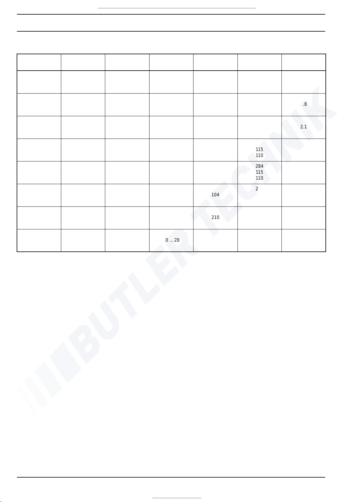
Circulationpump type
Volume flow Nominal voltage
Operating
voltage range
Nominal power
consumption
Dimensions Weight
l/h V – V – W
length
width
height
kg
U 4810
1600 (at approx.
0.15 bar)
12 or 24 10 …14 / 20 …28 25
173
94
77
0.8
U 4814
5000 (at approx.
0.2 bar)
12 or 24 10 …14 / 20 …28 104
228
100
105
2.1
U 4851
6000 (at approx.
0.4 bar)
24 20 …28 209
279
115
110
2.7
U 4852
6000 (at approx.
0.4 bar)
24 20 …28 209
284
115
110
2.95
U 4854
5200 (at approx.
0.15 bar)
24 20 …28 104
221
100
105
2.1
U 4855
6000 (at approx.
0.4 bar)
24 20 …28 210
225
110
115
2.4
U 4856
6000 (at approx.
0.4 bar)
24 20 …28 210
229
110
115
2.5
Visit www.butlertechnik.com for more technical information and downloads.
www.butlertechnik.com
 Loading...