

Spheros CC335SL, CC335DL, CC355 Operation Manual

CC335/CC355
To receive the best performance from the air conditioning system, we
suggest carefully reading this manual before operating the unit.
Keep this manual in the vehicle for future reference.
02/2013
P.N. 10000035A
Air Conditioning System
Operation Manual
CC335SL / CC335DL / CC355

CC335/CC355
Table of Contents
Page
INTRODUCTION……………………………………………………………………………….
2
SAFETY PRECAUTIONS……………………………………………………………………...
3
SPECIFIC WARNINGS………………………………………………………………………...
4
1 -
EQUIPMENT GENERAL ARRANGEMENT…………………………………………………
6
1.1 -
CC335 / 355 AIR CONDITIONER COMPONENTS………………………………..
6
2 -
CONTROLS AND INDICATORS……………………………………………………………...
7
2.1 -
FUNCTION OF THE MANUAL CONTROL PANEL………………………………..
7
2.2 -
MANUAL CONTROL AC REGULATION……………………………………………
8 2.3 -
FUNCTION OF THE DIGITAL CONTROL PANEL…………………………………
9
2.4 -
FUNCTION OF THE DIGITAL CONTROL AND INDICATOR…………………….
10
3 -
EQUIPMENT OPERATION……………………………………………………………………
11
3.1 -
COMMAND DESCRIPTION – NORMAL OPERATION……………………………
11
3.2 -
COMMAND DESCRIPTION – FAILURE MODE……………………………………
12 3.3 -
ELECTRICAL MALFUNCTIONS……………………………………………………..
13
3.4 -
AIR CONDITIONING SYSTEM MALFUNCTIONS…………………………………
13
4 -
PREVENTIVE MAINTENANCE ACTIVITIES………………………………………………..
15
4.1 -
GENERAL………………………………………………………………………………
15
4.2 -
PREVENTIVE MAINTENANCE SCHEDULE……………………………………….
16
5 -
TECHNICAL SPECIFICATIONS………………………………………………………………
17
6 -
FAILURE DIAGNOSIS TABLE………………………………………………………………..
18
7 -
ELECTRICAL SCHEMATICS OF RELAY BOARD AND CONTROL PANEL……………
20
7.1 -
RELAY AND FUSE LOCATION………………………………………………………
20
7.2 -
RELAY BOARD SCHEMATIC………………………………………………………..
21
8 -
ELECTRIC SCHEMATIC OF DIGITAL CONTROL PANEL AND RELAY BOARD..........
22
8.1 -
DIGITAL CONTROL PANEL………………………………………………………….
22
8.2 -
RELAY BOARD GL-R1HSP002 (12V) LAYOUT……………………….…………..
23
8.3 -
RELAY BOARD GL-R1HSP002 WIRING SCHEMATIC…………………………..
24
8.4 -
RELAY BOARD GL-T047 (24V) LAYOUT…………………………………………..
25
8.5 -
RELAY BOARD GL-T047 WIRING SCHEMATIC………………………………….
26
1

CC335/CC355
INTRODUCTION
At Spheros, we develop our products with the goal of providing a comfortable environment for vehicle passengers. We are always
looking for the best air condition concepts that provide the highest performance at the best possible value.
The compact systems are simple to operate and provide high cooling capacities at low noise levels.
This manual was developed with the purpose of presenting critical functional aspects, describing the ease of operation and
recommended maintenance necessary to obtain the best performance from the Spheros Air Conditioning system.
To ensure a long, useful and problem free life from the equipment it is essential that the operation and maintenance instructions
described in this manual are followed routinely and thoroughly.
All system controls provided by Spheros, are duly illustrated and explained in this manual.
It is important that the operator reads and understands the operation instructions carefully before starting the air conditioning
equipment.
Spheros makes every effort to maintain a network of authorized service professionals trained to perform any type of maintenance
within the quality standard.
Thank you for choosing Spheros Air Conditioning products. If you have any questions or concerns with our products, please contact
us or the nearest authorized service provider.
Spheros Climate Systems, LLC
5536 Research Drive
Canton, MI 48188
Phone 1-734-218-7350 Toll free 1-888-960-4849
2

CC335/CC355
SAFETY PRECAUTIONS
GENERAL SAFETY NOTICES
The following safety notices supplement warnings and cautions appearing elsewhere in this manual. The following are
recommended precautions that must be understood and applied during operation and maintenance of the equipment. Failure to
adhere to warnings and cautions may result in damage to equipment, fire, personal injury and even death.
OPERATING PRECAUTIONS
Keep hands, clothing and tools clear of the evaporator and condenser fans.
No work should be performed on the system unless battery power is disconnected.
In case of severe vibration or unusual noise, stop the system and investigate.
MAINTENANCE PRECAUTIONS
Always wear protective eye wear (safety glasses or goggles) and appropriate safety wear.
Never perform any maintenance or service on your equipment before consulting with authorized service personnel. Always unplug
unit before attempting any maintenance.
Avoid breathing any refrigerant vapor, lubricant vapor, or mist. Exposure to these, particularly PAG oil mist may irritate your eyes,
nose, or throat.
Never use compressed air (shop-air) to leak-test or pressure test a R134A system. Under certain conditions, pressurized mixtures of
R134A and air can be combustible. In addition, shop air will inject moisture into the system.
Always use mineral oil to lubricate “O” Rings, hoses, and fittings on R134A systems. PAG oils absorb moisture and become very
acidic and corrosive. Mineral oil does not absorb moisture and thus prevents corrosion. Always wear gloves when working with PAG
(Polyalkylene Glycol) and Ester (POE or Polyester) lubricants to prevent irritation to your skin. R134A lubricants can damage
vehicles paint, plastic parts, engine drive belts and coolant hoses.
Beware of unannounced starting of the evaporator and condenser fans. Do not remove the evaporator/condenser cover without
disconnecting the vehicle battery cable. Be sure power is turned off before working on motors, controllers, and electrical control
switches. Tag system controls and vehicle battery to prevent accidental energizing of the system.
In case of electrical fire, extinguish with CO2 (never use water). Disconnect vehicle battery power if possible.
3

CC335/CC355
SPECIFIC WARNINGS AND CAUTIONS
Be aware of unannounced starting of the evaporator and condenser fans. The unit may cycle the fans and compressor
unexpectedly as control requirements dictate.
The refrigerant contained in the air conditioning system when in direct contact with skin and eyes can cause frostbite,
severe burns or blindness.
Be sure to observe warning listed in the safety precautions in the front of this manual before performing maintenance
on the air conditioning system.
Never use air for leak testing. Pressurized, air-rich mixtures of refrigerants and air are combustible when
exposed to ignition source.
WARNING
WARNING
WARNING
WARNING
4
CC335/CC355
SPECIFIC WARNINGS AND CAUTIONS
Do not use a nitrogen cylinder without a pressure regulator. Do not use oxygen in or near a refrigeration
system as an explosion may occur.
The filter-drier may contain liquid refrigerant. Slowly open the fitting nuts and avoid contact with exposed
skin or eyes.
Unless there was a catastrophic failure, such as a blown or ruptured refrigerant hose, additional oil may
not be needed.
Use only the exact oil specified by the compressor manufacturer. Use of oil other than that specified will
void the compressor warrant
WARNING
WARNING
CAUTION
CAUTION
5
CC335/CC355
1. Equipment General Arrangement
1.1 CC335 / CC355 Air Conditioner Components
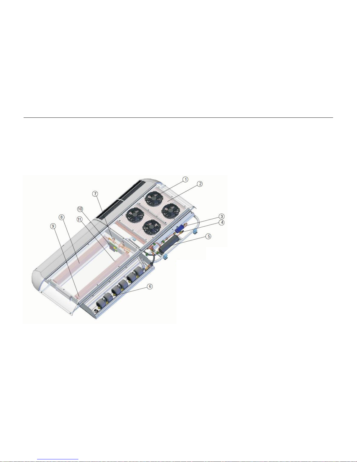
The CC335 / CC355 air conditioner and its main components are shown in Fig. 1.
Fig. 1
6
1. Condenser Fan
2. Condenser Coil
3. Filter Drier
4. Globe Valve
5. Receiver
6. Evaporator Blower
7. Expansion Valve
8. Left Evaporator Coil
9. Right Evaporator Coil
10. Relay Board
11. Evaporator Temperature Sensor

CC335/CC355
2. Controls and Indicators
2.1 Functions of the Manual Control Panel
The air conditioner control panel (one for single loop system and two for dual loop system) has two rotary switches, one for the
blower speed (E) and one for the temperature adjustment (G). It also has an LED indicator (F) to signal activation of the AC
compressor drive clutch. Figure 2 shows the features of the control panel.
Fig. 2: Manual Control Panel
Temperature Adjustment Switch
The Temperature Adjust Switch (G) is used to set the ideal or desired temperature level for the user. This can be varied between
approximately 64°F (18°C) and 78°F (26°C). The system is then automatically regulated and operates until the set value is obtained.
Cooling Compressor LED
The LED indicator (F) lights blue while the AC Compressor Clutch is activated, the condenser fans are running and the cooling
system is active. The LED turns off when the cabin temperature falls to the set level.
The Blower Switch
The blower motors have three modes of operation controlled by the Blower Switch (E) – Low, Medium and High speed. The blowers
do not run and no cooling occurs at the OFF position (A).
The Low (B) Medium (C) and High (D) switch positions keep the blowers continuously running at low, medium or high fixed speeds
respectively, independent of the set or actual temperature values.
A: A/C System OFF
B: Blower Switch, Low Mode
C: Blower Switch, Medium Mode
D: Blower Switch, High Mode
E: Blower Switch
F: Compressor Operation LED
G: Temperature Adjust Switch
7
CC335/CC355
2.2 Manual Control AC Regulation
AC Regulation
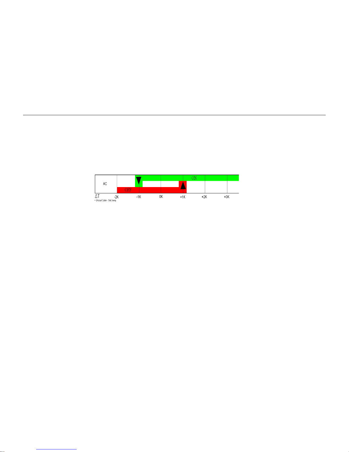
The A/C regulation is based on the difference between the actual cabin temperature and the set value. This is
Illustrated in Figure 3
Fig. 3: AC Regulation
Cooling (activated A/C Compressor Clutch and Condenser Fans) starts only after the temperature difference exceeds 1.8°F/1°C and
stops when the cabin temperature difference is 1.8°F/1°C less than the set value.
8
 Loading...