


CC335/CC355
To receive the best performance from the air conditioning system, we
suggest carefully reading this manual before operating the unit.
Keep this manual in the vehicle for future reference.
02/2013
P.N. 10000035A
Air Conditioning System
Operation Manual
CC335SL / CC335DL / CC355

CC335/CC355
Table of Contents
Page
INTRODUCTION……………………………………………………………………………….
2
SAFETY PRECAUTIONS……………………………………………………………………...
3
SPECIFIC WARNINGS………………………………………………………………………...
4
1 -
EQUIPMENT GENERAL ARRANGEMENT…………………………………………………
6
1.1 -
CC335 / 355 AIR CONDITIONER COMPONENTS………………………………..
6
2 -
CONTROLS AND INDICATORS……………………………………………………………...
7
2.1 -
FUNCTION OF THE MANUAL CONTROL PANEL………………………………..
7
2.2 -
MANUAL CONTROL AC REGULATION……………………………………………
8 2.3 -
FUNCTION OF THE DIGITAL CONTROL PANEL…………………………………
9
2.4 -
FUNCTION OF THE DIGITAL CONTROL AND INDICATOR…………………….
10
3 -
EQUIPMENT OPERATION……………………………………………………………………
11
3.1 -
COMMAND DESCRIPTION – NORMAL OPERATION……………………………
11
3.2 -
COMMAND DESCRIPTION – FAILURE MODE……………………………………
12 3.3 -
ELECTRICAL MALFUNCTIONS……………………………………………………..
13
3.4 -
AIR CONDITIONING SYSTEM MALFUNCTIONS…………………………………
13
4 -
PREVENTIVE MAINTENANCE ACTIVITIES………………………………………………..
15
4.1 -
GENERAL………………………………………………………………………………
15
4.2 -
PREVENTIVE MAINTENANCE SCHEDULE……………………………………….
16
5 -
TECHNICAL SPECIFICATIONS………………………………………………………………
17
6 -
FAILURE DIAGNOSIS TABLE………………………………………………………………..
18
7 -
ELECTRICAL SCHEMATICS OF RELAY BOARD AND CONTROL PANEL……………
20
7.1 -
RELAY AND FUSE LOCATION………………………………………………………
20
7.2 -
RELAY BOARD SCHEMATIC………………………………………………………..
21
8 -
ELECTRIC SCHEMATIC OF DIGITAL CONTROL PANEL AND RELAY BOARD..........
22
8.1 -
DIGITAL CONTROL PANEL………………………………………………………….
22
8.2 -
RELAY BOARD GL-R1HSP002 (12V) LAYOUT……………………….…………..
23
8.3 -
RELAY BOARD GL-R1HSP002 WIRING SCHEMATIC…………………………..
24
8.4 -
RELAY BOARD GL-T047 (24V) LAYOUT…………………………………………..
25
8.5 -
RELAY BOARD GL-T047 WIRING SCHEMATIC………………………………….
26
1

CC335/CC355
INTRODUCTION
At Spheros, we develop our products with the goal of providing a comfortable environment for vehicle passengers. We are always
looking for the best air condition concepts that provide the highest performance at the best possible value.
The compact systems are simple to operate and provide high cooling capacities at low noise levels.
This manual was developed with the purpose of presenting critical functional aspects, describing the ease of operation and
recommended maintenance necessary to obtain the best performance from the Spheros Air Conditioning system.
To ensure a long, useful and problem free life from the equipment it is essential that the operation and maintenance instructions
described in this manual are followed routinely and thoroughly.
All system controls provided by Spheros, are duly illustrated and explained in this manual.
It is important that the operator reads and understands the operation instructions carefully before starting the air conditioning
equipment.
Spheros makes every effort to maintain a network of authorized service professionals trained to perform any type of maintenance
within the quality standard.
Thank you for choosing Spheros Air Conditioning products. If you have any questions or concerns with our products, please contact
us or the nearest authorized service provider.
Spheros Climate Systems, LLC
5536 Research Drive
Canton, MI 48188
Phone 1-734-218-7350 Toll free 1-888-960-4849
2

CC335/CC355
SAFETY PRECAUTIONS
GENERAL SAFETY NOTICES
The following safety notices supplement warnings and cautions appearing elsewhere in this manual. The following are
recommended precautions that must be understood and applied during operation and maintenance of the equipment. Failure to
adhere to warnings and cautions may result in damage to equipment, fire, personal injury and even death.
OPERATING PRECAUTIONS
Keep hands, clothing and tools clear of the evaporator and condenser fans.
No work should be performed on the system unless battery power is disconnected.
In case of severe vibration or unusual noise, stop the system and investigate.
MAINTENANCE PRECAUTIONS
Always wear protective eye wear (safety glasses or goggles) and appropriate safety wear.
Never perform any maintenance or service on your equipment before consulting with authorized service personnel. Always unplug
unit before attempting any maintenance.
Avoid breathing any refrigerant vapor, lubricant vapor, or mist. Exposure to these, particularly PAG oil mist may irritate your eyes,
nose, or throat.
Never use compressed air (shop-air) to leak-test or pressure test a R134A system. Under certain conditions, pressurized mixtures of
R134A and air can be combustible. In addition, shop air will inject moisture into the system.
Always use mineral oil to lubricate “O” Rings, hoses, and fittings on R134A systems. PAG oils absorb moisture and become very
acidic and corrosive. Mineral oil does not absorb moisture and thus prevents corrosion. Always wear gloves when working with PAG
(Polyalkylene Glycol) and Ester (POE or Polyester) lubricants to prevent irritation to your skin. R134A lubricants can damage
vehicles paint, plastic parts, engine drive belts and coolant hoses.
Beware of unannounced starting of the evaporator and condenser fans. Do not remove the evaporator/condenser cover without
disconnecting the vehicle battery cable. Be sure power is turned off before working on motors, controllers, and electrical control
switches. Tag system controls and vehicle battery to prevent accidental energizing of the system.
In case of electrical fire, extinguish with CO2 (never use water). Disconnect vehicle battery power if possible.
3

CC335/CC355
SPECIFIC WARNINGS AND CAUTIONS
Be aware of unannounced starting of the evaporator and condenser fans. The unit may cycle the fans and compressor
unexpectedly as control requirements dictate.
The refrigerant contained in the air conditioning system when in direct contact with skin and eyes can cause frostbite,
severe burns or blindness.
Be sure to observe warning listed in the safety precautions in the front of this manual before performing maintenance
on the air conditioning system.
Never use air for leak testing. Pressurized, air-rich mixtures of refrigerants and air are combustible when
exposed to ignition source.
WARNING
WARNING
WARNING
WARNING
4
CC335/CC355
SPECIFIC WARNINGS AND CAUTIONS
Do not use a nitrogen cylinder without a pressure regulator. Do not use oxygen in or near a refrigeration
system as an explosion may occur.
The filter-drier may contain liquid refrigerant. Slowly open the fitting nuts and avoid contact with exposed
skin or eyes.
Unless there was a catastrophic failure, such as a blown or ruptured refrigerant hose, additional oil may
not be needed.
Use only the exact oil specified by the compressor manufacturer. Use of oil other than that specified will
void the compressor warrant
WARNING
WARNING
CAUTION
CAUTION
5
CC335/CC355
1. Equipment General Arrangement
1.1 CC335 / CC355 Air Conditioner Components
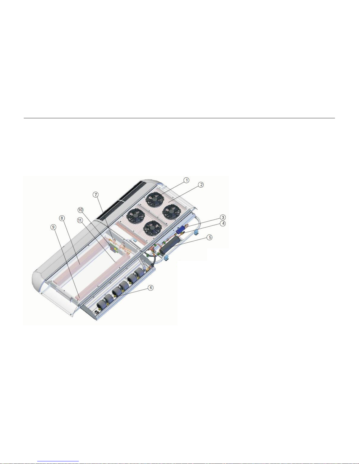
The CC335 / CC355 air conditioner and its main components are shown in Fig. 1.
Fig. 1
6
1. Condenser Fan
2. Condenser Coil
3. Filter Drier
4. Globe Valve
5. Receiver
6. Evaporator Blower
7. Expansion Valve
8. Left Evaporator Coil
9. Right Evaporator Coil
10. Relay Board
11. Evaporator Temperature Sensor

CC335/CC355
2. Controls and Indicators
2.1 Functions of the Manual Control Panel
The air conditioner control panel (one for single loop system and two for dual loop system) has two rotary switches, one for the
blower speed (E) and one for the temperature adjustment (G). It also has an LED indicator (F) to signal activation of the AC
compressor drive clutch. Figure 2 shows the features of the control panel.
Fig. 2: Manual Control Panel
Temperature Adjustment Switch
The Temperature Adjust Switch (G) is used to set the ideal or desired temperature level for the user. This can be varied between
approximately 64°F (18°C) and 78°F (26°C). The system is then automatically regulated and operates until the set value is obtained.
Cooling Compressor LED
The LED indicator (F) lights blue while the AC Compressor Clutch is activated, the condenser fans are running and the cooling
system is active. The LED turns off when the cabin temperature falls to the set level.
The Blower Switch
The blower motors have three modes of operation controlled by the Blower Switch (E) – Low, Medium and High speed. The blowers
do not run and no cooling occurs at the OFF position (A).
The Low (B) Medium (C) and High (D) switch positions keep the blowers continuously running at low, medium or high fixed speeds
respectively, independent of the set or actual temperature values.
A: A/C System OFF
B: Blower Switch, Low Mode
C: Blower Switch, Medium Mode
D: Blower Switch, High Mode
E: Blower Switch
F: Compressor Operation LED
G: Temperature Adjust Switch
7
CC335/CC355
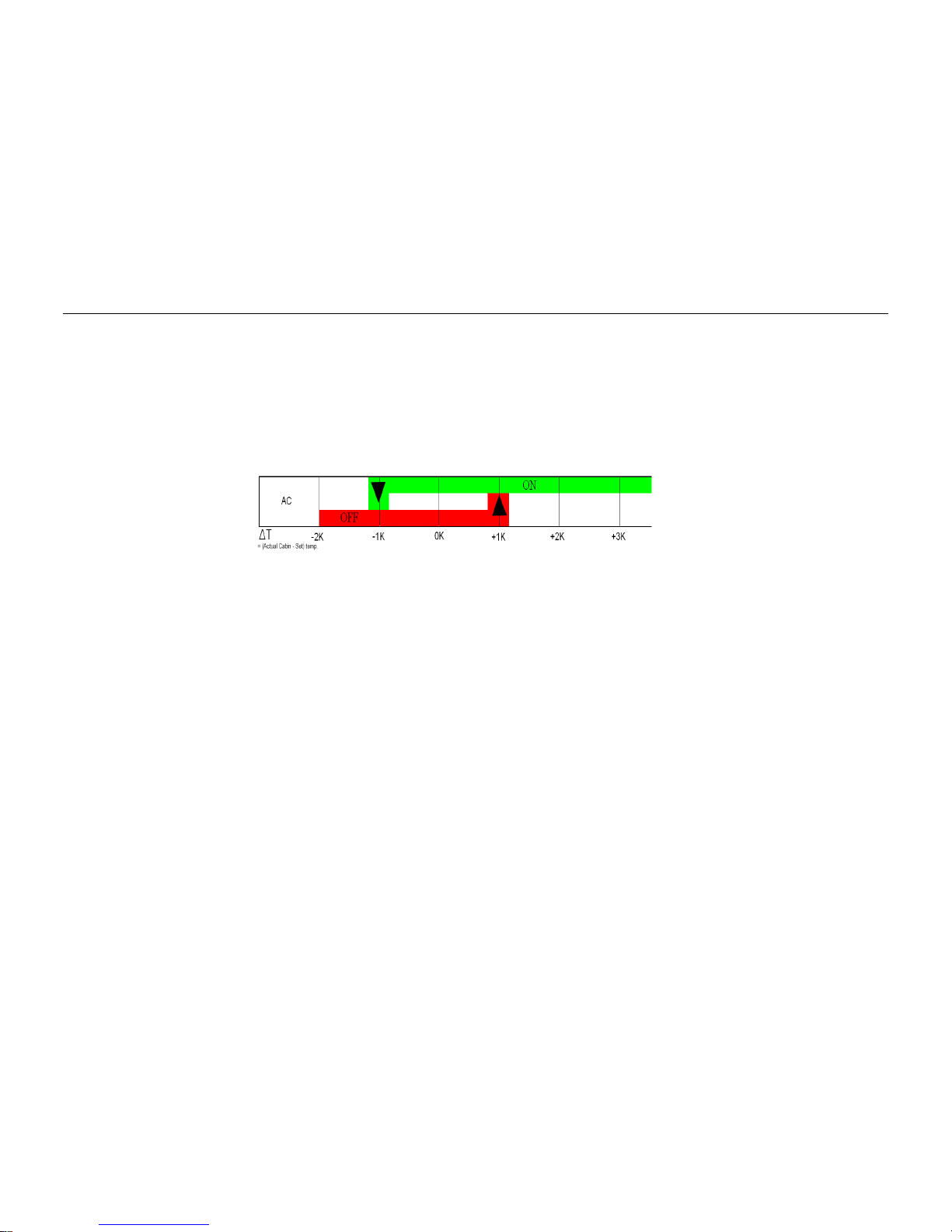
2.2 Manual Control AC Regulation
AC Regulation
The A/C regulation is based on the difference between the actual cabin temperature and the set value. This is
Illustrated in Figure 3
Fig. 3: AC Regulation
Cooling (activated A/C Compressor Clutch and Condenser Fans) starts only after the temperature difference exceeds 1.8°F/1°C and
stops when the cabin temperature difference is 1.8°F/1°C less than the set value.
8
CC335/CC355
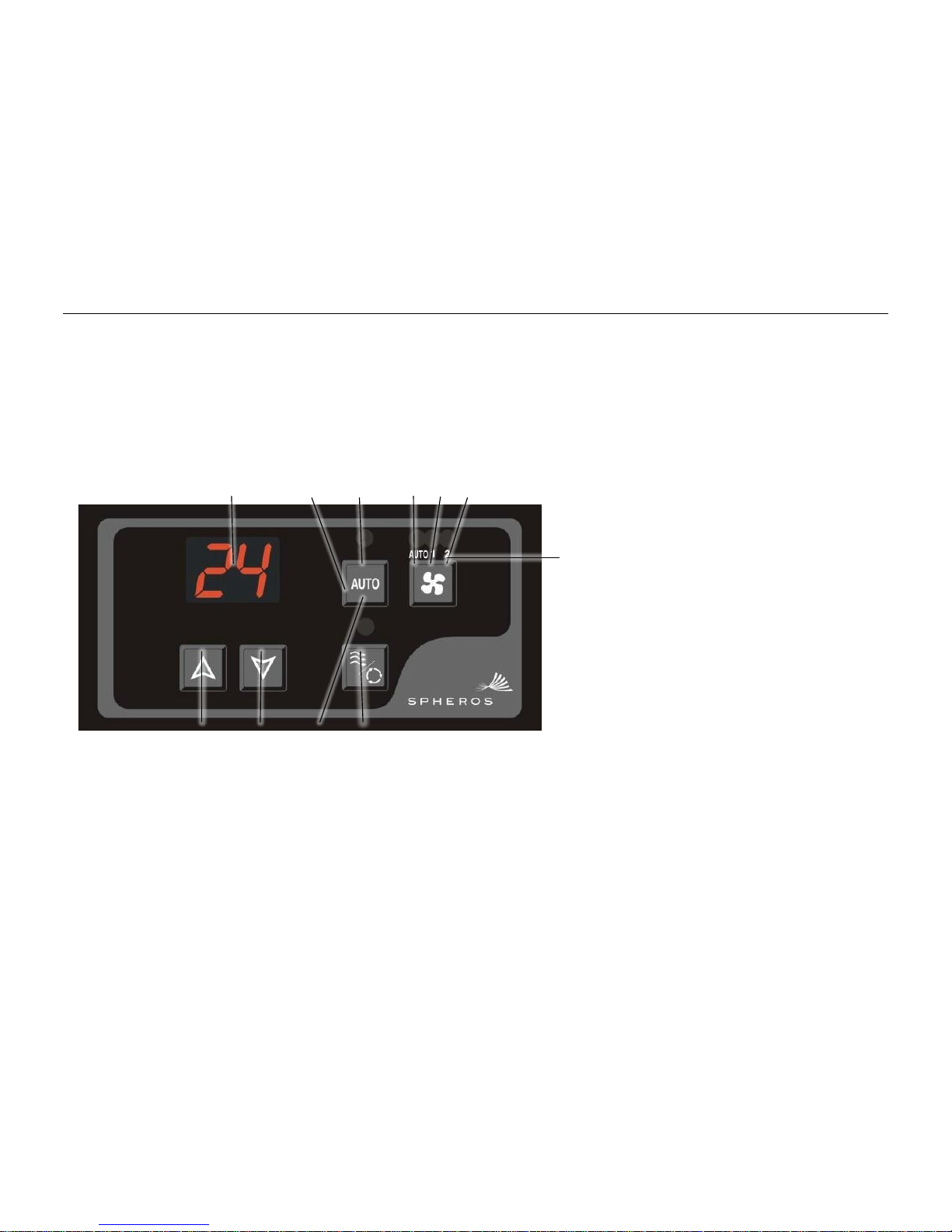
2.3 Functions of the Digital Control Panel
The air conditioner control panel has a main CPU and a keyboard to control the operation of the system and provides visual
display of operation status. The control panel and its controls and indicators are shown in Fig. 4.
Fig. 4: Automatic Control Panel
1. Numeric Display
2. Cooling Control Key
3. A/C On LED
4. Auto Mode LED
5. Ventilation Low Speed (LO) LED
6. Ventilation HI Speed (HI) LED
7. Ventilation Control Key
8. Fresh Air Key (Optional)
9. Fresh Air Vent Open LED
10. Set Point Down Key
11. Set Point Up Key
11
10
9
8
9

CC335/CC355
2.4 Function of Electronic Control and Indicators
The function of the controls and indicators is shown in Fig. 5.
Note:
All keys have backlit red LED’s,
Index Fig. 2
Control / Indicator
Setting / Indication
Function
1
Display
°F
Ignition on, system in standby for activation by pressing
Auto Key.
Ventilation only is possible by pressing Ventilation Key.
Number or Code
System in operation. Indication of temperatures,
ventilation speed, failure codes and status information
depending on system operational mode and indication
selections. For details refer to “Command Description”.
2
Auto Mode ON/OFF
Key
Pressed
The controller will automatically chose one of the
available functions (cooling or heating).
3
Auto Mode ON LED
Lit
A/C mode is on, system operates in air conditioning or
heating mode.
4
AUTO Ventilation
Mode LED
Lit
AUTO Fan Speed Mode is on, fan operates in AUTO
Mode.
5
LOW Speed
Ventilation LED
Lit
Indication of Low Speed Ventilation manually selected
with ventilation key. AUTO mode LED is off.
6
HI Speed
Ventilation LED
Lit
Indication of HI Speed Ventilation manually selected
with ventilation key. AUTO mode LED is off.
7
Ventilation Control
Key
Pressed
Ventilation Mode provides two operation speeds of the
fan.
8
Fresh Air Key
Pressed
Allows external air to enter the vehicle and can be
automatic depending upon internal temperature.
9
Fresh Air Vent Open
Led
Lit
Indication of Fresh Air Vent Open and Off when vent is
closed.
10
Set Point Down Key
Pressed
Lowers Temperature Set Point and operating
parameters
11
Set Point Up Key
Pressed
Raises Temperature Set Point and operating
parameters
Fig. 5 Function of Controls and Indicators
10
CC335/CC355
3. Equipment Operation
3.1 Command Description – Normal Operation
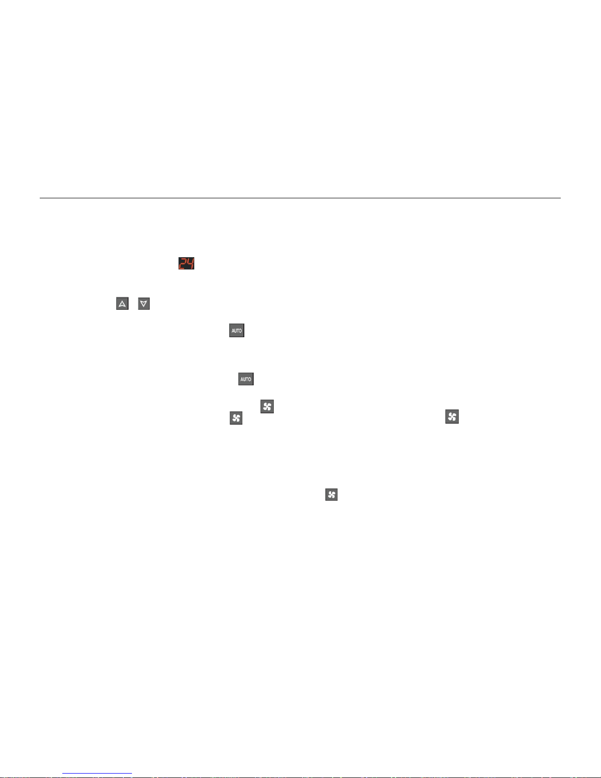
Display
The two digit numeric display is used for informing the operator about the selected set temperature.
Set-Point
The set-point is the desired temperature inside the vehicle. The actual selected set point temperature blinks and may be adjusted by
pressing the or keys.
Automatic Mode
1 - To select the Automatic Mode press the key.
In the Automatic Mode the controller will automatically chose one of the available functions (cooling or heating), according to the
set point temperature.
2 – To disable the Automatic Mode, press the key again.
Ventilation Mode
The Ventilation function is activated by pressing the key.
There are two operation speeds. Press the key once to select the LO ventilation speed, press the key a second time to
select HI ventilation speed.
Cooling Mode
After selecting the Automatic Mode and the internal temperature of the vehicle is above the desired set point, the system will start
operating in the cooling mode and selects the evaporator blower speed automatically.
When the system starts up in the cooling mode the evaporator’s blowers will start in the automatic mode according to the set point
programming. Ventilation speeds may be changed manually with the key.
11
CC335/CC355
3.2 Command Description – Failure Operation
Failure Operation – Control Panel Functions
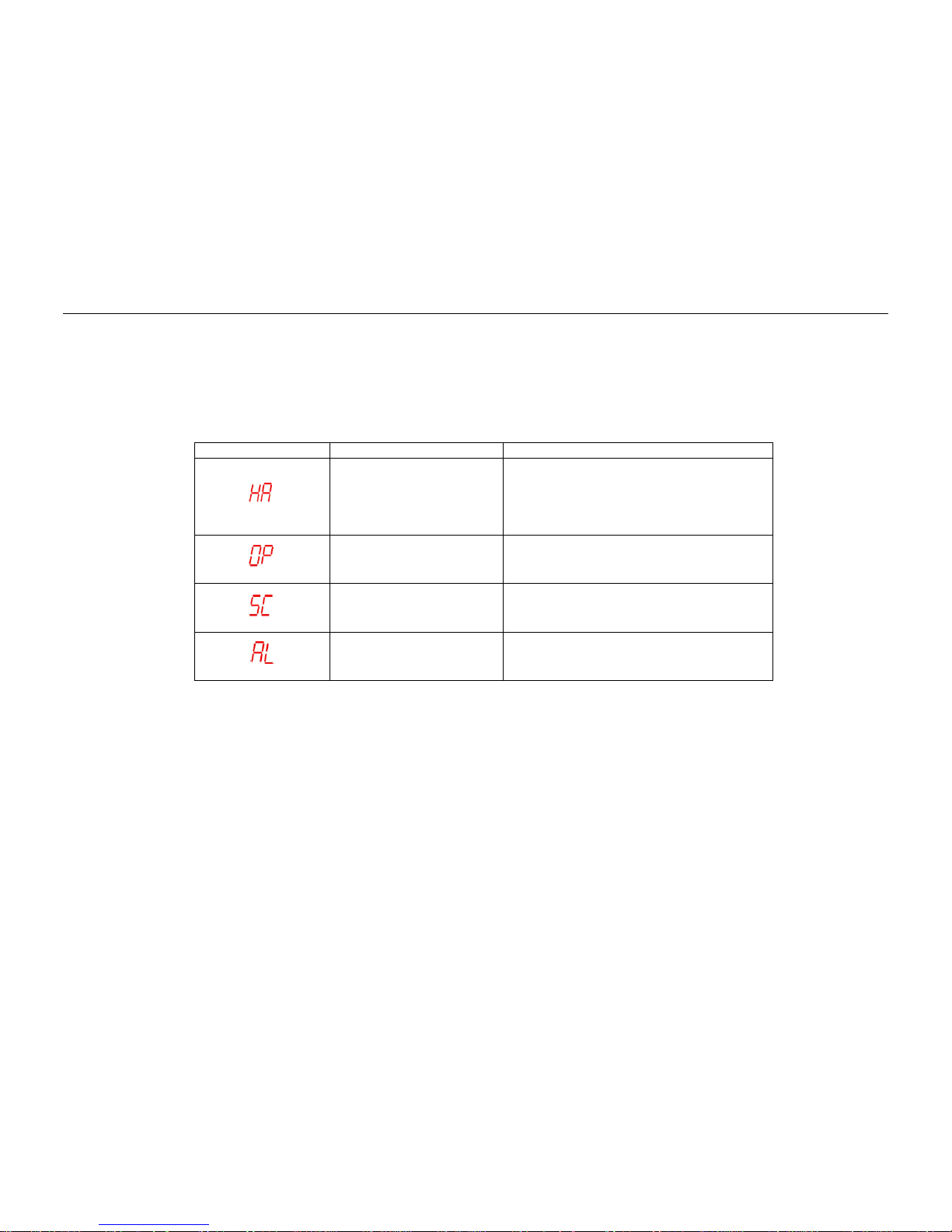
The system indicates failure codes on the display. The possible failure codes and their meanings are shown in Fig. 6.
Failure
Possible Cause
Check and Correct
Pressure switch failure
Anti-Icing Thermostat
Failure
Check pressure switch
Check anti-icing thermostat
Check evaporator
Check refrigerant pressure
Check evaporator blowers
Temperature Sensor Open
Check condition of temperature sensor
Check temperature sensor wiring
Temperature Sensor Short
Circuit
Check condition of temperature sensor
Check temperature sensor wiring
Electrical Power Failure
Check battery voltage
Check wiring
Check alternator
Fig. 6 Failure Code Indications
1 – If any failure occurs to the pressure switch, the display will show the message (HA) and the system will shut the compressor off.
The Controller has a 30 minute delay before allowing the compressor and condenser fans to restart.
2 – As the system operates according to the internal temperature, the controller has two failure codes to monitor the temperature
Sensors:
a) If the temperature sensor is open, the display will show (OP).
b) If the temperature sensor is shorted, the display will show (SC).
3 – The controller has a parameter to monitoring the alternator. If a failure occurs the display will show (AL).
12

CC335/CC355
3.3 Electrical Malfunctions
The individual circuits are to be checked systematically in accordance with the wiring diagram. The plug connections and electrical
components such as switches, relay, etc. should be checked.
The following are possible causes of electrical malfunctions and should always be checked first so they can be excluded as the
cause of the failure:
- Corroded plug contacts
- Loose plug contacts
- Corroded wires
- Corroded battery terminals
- Broken wires
- Defective fuses
3.4 Air Conditioning System Malfunctions
The following failures may occur in the air conditioning system and may lead to a fault lockout of the system:
- Activated freeze protection sensor
- Activated high / low pressure switch
- Defective compressor
- Defective evaporator or condenser fans
- Refrigerant loss due to leaks
- Plugged air filter or dirty heat exchanger fins
- Restricted refrigeration circuit (filter drier)
- Defective expansion valve
3.5 Malfunctions in the Refrigeration Circuit
If malfunctions occur in the refrigeration circuit of the air conditioning system, the system must be checked and properly repaired by
an authorized air conditioning service professional.
CAUTION
The refrigerant is not allowed to be released to the atmosphere. Regulatory requirements mandate that individuals who
open a system or container containing a controlled refrigerant be certified.
13

CC335/CC355
Check the refrigerant charge in the system:
- After the air conditioning system has been operating for approx. 5 min. with the electromagnetic clutch activated and the engine
running at a rapid idle, the refrigerant should flow through the sight glass without forming any bubbles.
During the cold season:
- To prevent the shaft seal of the compressor from drying out and leaking, operate the air conditioning system for approx. 15 min.
twice a month at ambient temperatures above 46°F (8°C).
The refrigerant receiver as well as all components of the air conditioning system should be visually inspected during the maintenance
activities. Special attention should be directed to any signs of corrosion and mechanical damage.
All components that are not in perfect condition must be replaced for safety reasons.
CAUTION
The pressure vessels directive requires the operator to have the refrigerant receiver checked by an authorized service
professional at regular intervals.
Note
To ensure trouble free operation of the air conditioner, the refrigeration oil and filter drier must be replaced 6 months after the initial
operation of the vehicle or if there is a change in color of oil.
a) Yellow – Normal oil
b) Black – Carbonized oil
c) Brown – Copper Corrosion, due to moisture in system
d) Metallic Gray – Suspended metallic particles
The filter drier should be replaced every year at the beginning of the season or every time system is exposed to contamination.
These activities must be performed by an authorized service company which should also perform a functional check of the air
conditioner as well as a leak test of the system.
Warranty claims can only be accepted if the claimant can prove that the maintenance and safety instructions have been strictly
observed.
14

CC335/CC355
4. Preventative Maintenance Activities
4.1 General
An air-conditioning system just as all other parts of the vehicle subjected to constant mechanical strain and stress. To ensure
trouble-free operation of the system and to avoid any damage to its parts, it is important that all required service activities on the air
conditioning system are performed by trained and qualified personnel who are knowledgeable in the field of refrigeration.
The proper handling of the system including proof of the service activities record is a prerequisite for acceptance of any warranty
claims in the event of damage to parts subject to maintenance.
Warranty replacement parts and out of warranty replacement parts must be supplied by Spheros Climate System, LLC to assure
the quality and reliability of the product.
Regardless of the maintenance intervals specified in the maintenance and service schedule, all attachments of the unit and the
connections of the refrigerant lines must be checked for tightness within the first four weeks following the initial start-up of the airconditioning system or the vehicle.
Even if the air-conditioning system is not in operation, wear caused by normal aging or the strain and stress occurring during the
driving operation of the bus may occur on individual components. All checks listed in the maintenance and service schedule need to
be independent of the operation hours of the system.
Loss of refrigerant is possible even if the refrigerant connections are tight due to the structure of the material of the refrigerant lines
and the ambient temperatures. In the event of a relatively high refrigerant loss within short intervals, leaks in the system can be
assumed.
During long periods of non-use, the air-conditioning system should be operated for about 15 minutes at least twice a month in order
to prevent the shaft seals of the compressor from hardening.
The drive pulley of the electromagnetic clutch is continuously rotating when the vehicle engine is in operation. Bearing wear or
possible damage to the clutch may occur and should be inspected independently of maintenance intervals based on the operating
time of the air-conditioning system. It is imperative that the clutch be checked for correct lubrication, belt tension etc.
CAUTION
- The refrigerant receiver is subject to the Pressure Equipment Directive. Check the receiver every 6 months for cracks,
mechanical damage or corrosion. The receiver must be replaced if any defects are found.
- The maintenance intervals indicated in the maintenance and service schedule are based on the operation hours of the vehicle,
with the exception of the compressor assembly, which are based on the air-conditioning unit’s hours of operation.
- These time intervals are empirical values that may vary widely depending on the type of system and type of bus concerned
15
CC335/CC355
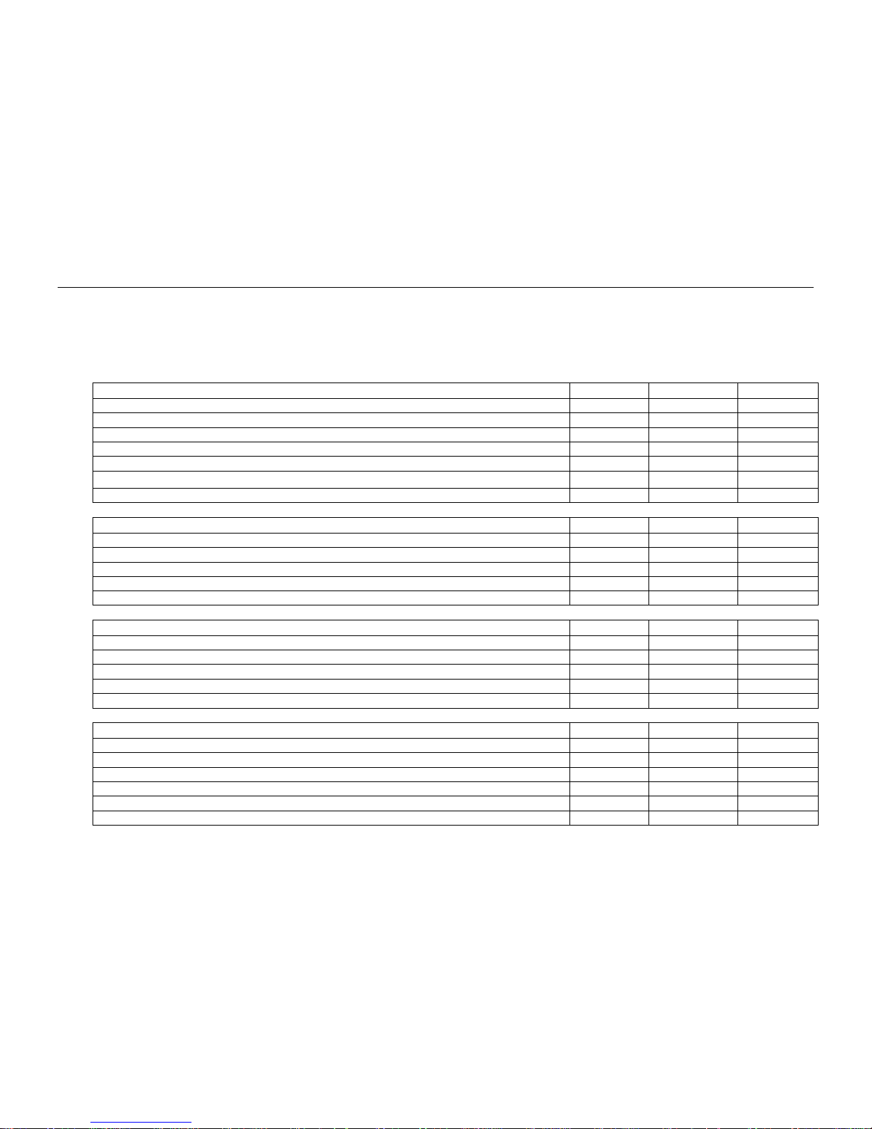
4.2 Preventive Maintenance Schedule
All preventive maintenance described below is based on typical operating conditions. The frequency outlined below is for
normal operating conditions and should increase if used under more sever conditions.
COOLING CIRCUIT
MONTHLY
QUARTERLY
ANNUALLY
Measure and record the refrigerant pressures and temperatures of the suction line
X
Measure and record the refrigerant pressures and temperatures of the liquid line
X
Visually inspect for signs of oil or refrigerant leaks
X
After 15 minutes of operation check refrigerant level using the sight glass
X
Visually inspect all components, tubes and hoses for signs of wear and deterioration
X
Change the filter drier once a year or each time the system is opened
X
Check the opening and closing pressures of the high and low pressure switches
X
COMPRESSOR / CLUTCH
MONTHLY
QUARTERLY
ANNUALLY
Visually inspect the clutch plate
X
Visually inspect the condition, tension and alignment of the compressor belts
X
Clean the compressor and clutch with steam or hot water
X
Measure the resistance and the voltage on the clutch coil
X
Check the compressor oil level after 15 minutes of operation
X
STRUCTURE
MONTHLY
QUARTERLY
ANNUALLY
Visually inspect for loose parts, damaged or broken wires
X
Clean or replace the return air filters
X
Clean the condenser and evaporator drains
X
Clean the fins the evaporator and condenser coils with coil cleaner or soap and water
X
Retighten all bolts on the compressor support and the unit using recommended torque
ELECTRICAL SYSTEM
MONTHLY
QUARTERLY
ANNUALLY
Check control panel operation, clean panel and thermostat sensor with air
X
Check the alternator for corrosion and inspect electrical connections
X
Visually check the alternator belt tension, check for mis-alignment and wear
X
Check the power cable at the relay plate, re-torque if necessary
X
Inspect all wires and terminals for damage and corrosion
X
Check the ventilation of the condenser and evaporator motors
X
Note: We recommend using this table to develop a plan for routine maintenance to you A/C System
16

CC335/CC355
IMPORTANT: The return air filter and the condenser coil must be checked and cleaned weekly. As a rule, the air ducts must be
cleaned every 3 months and more frequently depending on operating times of the system, the number of passengers and the
severity of the environmental conditions.
A cost effective preventive maintenance program can prevent costly down time and repairs and avoid cancellation of
warranty due to negligence.
5. Technical Specifications
The main specifications for the air conditioning system are shown in Fig. 7.
Technical Data
CC335 SINGLE LOOP
CC335 DUAL LOOP
CC355
Max. Cooling Capacity (BTU/H) / (KW)*
120,000 / 35
109,000 / 32
136,500 / 40
Dimensions: Length x Width x Height (in) / (mm)
137 x 67 x 7.8 / 3.480 x 1.700 x 200
Weight (lbs) / (kg)
342 /155
350 / 160
364 / 165
Evaporator Air Flow (CFM) / (m³/h)
3,700 / 6,300
3,700 / 6,300
3,700 / 6,300
Maximum Outside Temperature (°F) / (°C)
140 / 60
140 / 60
140 / 60
Supply Voltage (VDC)
12V
12V
24V
Current Consumption @ 24 VDC / 12 V (AMPS)
160A
160A
91A
Refrigerant Type
R-134A
R-134A
R-134A
Number of Evaporator Blowers
6 6 6
Number of Condenser Fans
3 3 4
*Evaporator air in 104°F / 40°C, 46% RH, Ambient 95°F / 35°C.
Fig. 7 Technical Data
17

CC335/CC355
6. Failure Diagnosis Table
As a troubleshooting aide, the table in Fig. 8 lists possible failure symptoms, possible causes and solutions to assist in correcting
the problem.
Symptoms
Possible Cause
Solution
Compressor does not work
Fuse or relay defective
Replace fuse or relay
Magnetic clutch burned
Replace clutch
Compressor locked
Replace compressor
Low pressure switch open
Low on refrigerant or defective pressure switch
HP switch opens
Overcharge of refrigerant
Adjust refrigerant charge
Condenser coil dirty
Clean condenser coil
Condenser fan(s) not working
Replace fan(s)
Faulty HP switch
Replace HP switch
LP switch opens
Loss of refrigerant
Check for possible leak, adjust charge
Plugged or defective expansion valve
Replace the expansion valve
Dirty evaporator coil
Clean the evaporator coil
Dirty air filter
Clean or replace air filter
Evaporator blower(s) not working
Replace blower(s)
Faulty low pressure switch
Replace low pressure switch
Condenser Fan not working
Electrical wiring connection bad
Locate and repair connection
Burned fuse or defective control relay
Replace fuse and/or relay
Open winding in motor
Replace fan
Evaporator Blower not working
Electrical wiring connection bad
Locate and repair connection
Burned fuse or defective control relay
Replace fuse and/or relay
Open winding in motor
Replace blower
Fig. 8 Failure Diagnosis Table
18

CC335/CC355
Symptoms
Possible Cause
Solution
AC does not cool and
Low on refrigerant charge
Check for leaks, adjust charge
Compressor remains on
Non-Condensables in system
Evacuate the unit to 1000 microns or less
and adjust charge to correct amount
Plugged or defective expansion valve
Replace the expansion valve
Dirty evaporator coil
Clean the coil
Dirty air filters
Clean or replace air filters
AC cools down too much and
Incorrect temperature set point selection
Adjust desired set point temperature on
Compressor continues to run
control panel
Temperature sensor location
Check and relocate temperature sensor
High discharge pressure
Overcharge of refrigerant in system
Adjust charge to correct amount
Restriction in sealed system
Locate and remove restriction, compressor
valve partially closed, expansion valve
partially closed, filter drier plugged
Condenser fan not working
Refer to symptom “Condenser Fan not
Working”
Dirty condenser coil
Clean condenser coil
Low suction pressure
Low system charge
Check for leak, adjust charge
Return air temperature too low
Relocate temperature sensor
Plugged or defective expansion valve
Replace the expansion valve
Evaporator Blower(s) not working
Refer to symptom “Evaporator Blower(s) not
Working
Restriction in sealed system
Locate and remove restriction
Dirty air filters
Clean or replace air filters
Dirty evaporator coils
Clean evaporator coils
Fig. 8 Failure Diagnosis Table
19

CC335/CC355
7. Electrical Schematics of Relay Board for Manual Control Panel
7.1 Relay and Fuse Locations
RELAY
FUNCTION
TYPE FUSE
FUNCTION
TYPE
K1
Blower Fan 1 – High Speed
40A F1
Relay Coils
ISO8820 – 5A
K2
Blower Fan 3 – High Speed
40A F2
Condenser Clutch
ISO8820 – 10A
K3
Blower Fan 2 – High Speed
40A F3
Condenser Fan 1
ISO8820 – 25A
K4
Blower Fan 4 – High Speed
40A F4
Condenser Fan 2
ISO8820 – 25A
K5
Blower Fans 1 & 2 – Med. Speed
40A F5
Condenser Fan 3
ISO8820 – 25A
K6
Blower Fans 3 & 4 – Med. Speed
40A F6
Blower Fan 1
ISO8820 – 25A
K7
Condenser Fan 1 & Clutch Switch
40A F7
Blower Fan 2
ISO8820 – 25A
K8
Condenser Fan 2
40A F8
Blower Fan 3
ISO8820 – 25A
K9
Condenser Fan 3
40A F9
Blower Fan 4
ISO8820 – 25A
K10
Control relay
11115103A
K11
Blower Fans 1 & 2 – Low Speed
40A
K12
Blower Fans 3 & 4 – Low Speed
40A
20

CC335/CC355
7.2 Relay Board 11117762A with 11116024A Manual Control Panel Schematic
21
Control Panel
Male Connector
Relay Board X1 Connector
(Pin Side)
D+ = Alternator
15 = Ignition
30 = Battery
Optional
Noise
Suppression
Switch
Field Supplied
Clutch Relay
Recommended

CC335/CC355
1-EVAPORATOR FAN LOW
2-GND
3-CONDENSER FAN
4-EVAPORATOR FAN HIGH
5-INTERNAL TEMPERATURE SENSOR
8 Electrical Schematic for Digital Control Panel and Relay Board
8.1 Digital Control Panel
6-ALTERNATOR D+
7-+12V / +24V
8-PRESSURE SWITCH
9-TEMPERATURE SENSOR
22
Note: 4 pressure
switches for dual
loop

CC335/CC355
8.2 Relay Board GL-R1HSP002 (12V) Layout
FUSE
FUNCTION
SIZE RELAY
FUNCTION
SIZE RELAY
FUNCTION
SIZE
F1
CONDENSER FAN 1
30A RL1
EVAP. BLOWERS LO RELAYS
40A RL12
CONDENSER FANS & SOLENOID RELAYS
40A
F2
CONDENSER FAN 2
30A RL2
EVAP. BLOWERS HI RELAYS
40A RL13
CONDENSER FAN 3
40A
F3
EVAPORATOR 5
30A RL3
CONDENSER FAN 1
40A RL14
SOLENOID VALVES
40A
F4
EVAPORATOR 3
30A RL4
CONDENSER FAN 2
40A RL15
EVAPORATOR BLOWER 6 LO
40A
F5
EVAPORATOR 1
30A RL5
EVAPORATOR BLOWER 5 HI
40A RL16
EVAPORATOR BLOWER 6 HI
40A
F7
CLUTCH
15A RL6
EVAPORATOR BLOWER 5 LO
40A RL17
EVAPORATOR BLOWER 5 LO
40A
F8
CONDENSER FAN 3
30A RL7
EVAPORATOR 3 HI
40A RL18
EVAPORATOR BLOWER 5 HI
40A
F9
SOLENOID VALVES
10A RL8
EVAPORATOR 3 LO
40A RL19
EVAPORATOR BLOWER 2 LO
40A
F10
EVAPORATOR 6
30A RL9
EVAPORATOR 1 HI
40A RL20
EVAPORATOR BLOWER 2 HI
40A
F11
EVAPORATOR 4
30A RL10
EVAPORATOR 1 LO
40A
F12
EVPORATOR 2
30A
CN1
1. Condenser Fan 1
2. N.C.
3. Condenser Fan 2
4. N.C.
5. N.C.
6. N.C.
7. Condenser Fan 3
8. N.C.
9. Solenoid Valves
CN2
1. Evaporator 5 HI
2. N.C.
Evaporator 5 LO
3. N.C.
4. N.C.
5. N.C.
6. Evaporator 6 LO
7. N.C.
8. Evaporator 6 HI
CN3
1. Evaporator 3 HI
2. N.C.
3. Evaporator 3 LO
4. N.C.
5. N.C.
6. N.C.
7. Evaporator 4 LO
8. N.C.
9. Evaporator 4 HI
CN4
1. Evaporator 1 HI
2. N.C.
3. Evaporator 1 LO
4. N.C.
5. N.C.
6. N.C.
7. Evaporator 2 LO
8. N.C.
9. Evaporator 2 HI
CN5
1. N.C.
2. N.C.
3. Clutch
4. N.C.
5. N.C.
6. N.C.
7. N.C.
8. N.C.
9. D+
CN6
1. Cond/Clutch ON
2. N.C.
3. N.C.
4. GND
5. +12V After IGN
6. N.C.
7. Blowers HI
8. N.C.
9. Blowers LO
23

CC335/CC355
`12` 8.3 Wiring Schematic for GL-R1HSP002 (12V) Relay Board with GL-P1HSP002 Digital Control Panel
GL-P1HSP002
24
Note: 4 pressure
switches for dual
loop.
CC335/CC355
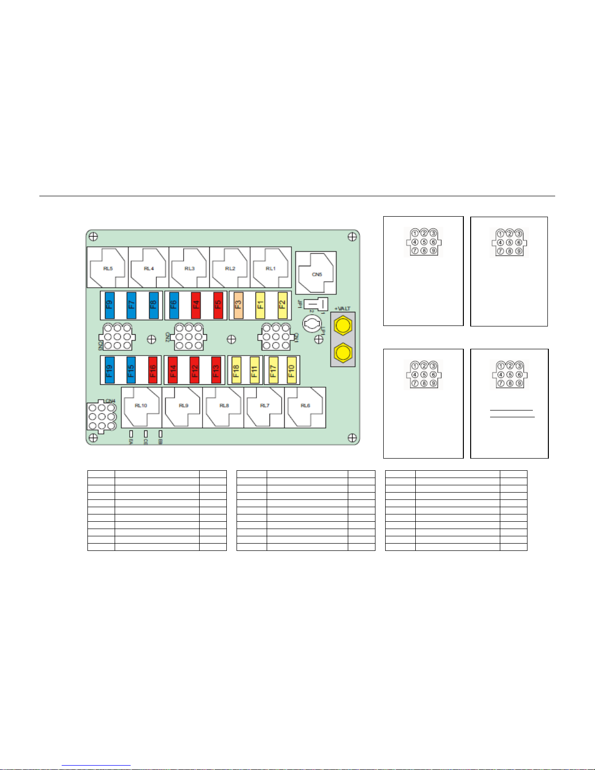
8.4 Relay Board GL-T047 (24V) Layout - CC355 SL
FUSE
FUNCTION
SIZE FUSE
FUNCTION
SIZE RELAY
FUNCTION
F1
CONDENSER FAN 1
15A F11
CONDENSER FAN 5
15A RL1
CONDENSER FAN 1, 2
40A
F2
CONDENSER FAN 2
15A F12
EVAPORATOR 4 LO
10A RL2
COMPRESSOR CLUTCH
40A
F3
COMPRESSOR CLUTCH
10A F13
EVAPORATOR 3 LO
10A RL3
EVAPORATOR 1, 2 LO
40A
F4
EVAPORATOR 1 LO
10A F14
EVAPORATOR 5 LO
10A RL4
EVAPORATOR 3, 4 HI
40A
F5
EVAPORATOR 2 LO
10A F15
EVAPORATOR 5 HI
15A RL5
EVAPORATOR 1, 2 HI
40A
F6
EVAPORATOR 4 HI
15A F16
EVAPORATOR 6 LO
10A RL6
CONDENSER 3,4
40A
F7
EVAPORATOR 2 HI
15A F17
CONDENSER FAN 4
15A RL7
CONDENSER 5,6
40A
F8
EVAPORATOR 3 HI
15A F18
CONDENSER FAN 6
15A RL8
EVAPORATOR 3, 4 LO
40A
F9
EVAPORATOR 1 HI
15A F19
EVAPORATOR 6 HI
15A RL9
EVAPORATOR 5, 6 LO
40A
F10
CONDENSER FAN 3
15A RL10
EVAPORATOR 5, 6 HI
40A
CN1
1. Condenser Fan 1
2. Condenser Fan 2
3. Condenser Fan 3
4. Compressor Clutch
5. Fresh Air
6. Alternator D+
7. Condenser Fan 6
8. Condenser Fan 5
9. Condenser Fan 4
CN3
1. Evaporator 1 HI
2. Evaporator 2 HI
3. Evaporator 3 HI
4. N.C.
5. Air Curtain
6. N.C.
7. Evaporator 6 HI
8. Evaporator 5 HI
9. Evaporator 4 HI
CN4
1. N.C.
2. Ground
3. Fresh Air HI ON
4. Fresh Air LO ON
5. +24V Ignition
6. Condenser Fan ON
7. +24V Direct
8. N.C.
9. N.C.
CN2
1. Evaporator 1 LO
2. Evaporator 2 LO
3. Evaporator 3 LO
4. N.C.
5. N.C.
6. N.C.
7. Evaporator 6 LO
8. Evaporator 5 LO
9. Evaporator 4 LO
25

CC335/CC355
8.5 Wiring Schematic for GL-T047 (24V) Relay Board with GL-P1HSP002 Digital Control Panel- CC355 SL
26
GL-P1HSP002
GL-T047

CC335/CC355
Spheros Climate Systems, LLC
5536 Research Drive
Canton, MI 48188 USA
Phone 1-734-218-7350, Toll free 1-888-960-4849
Fax 1-734-487-1569
www.spheros.us
 Loading...