

Page 1
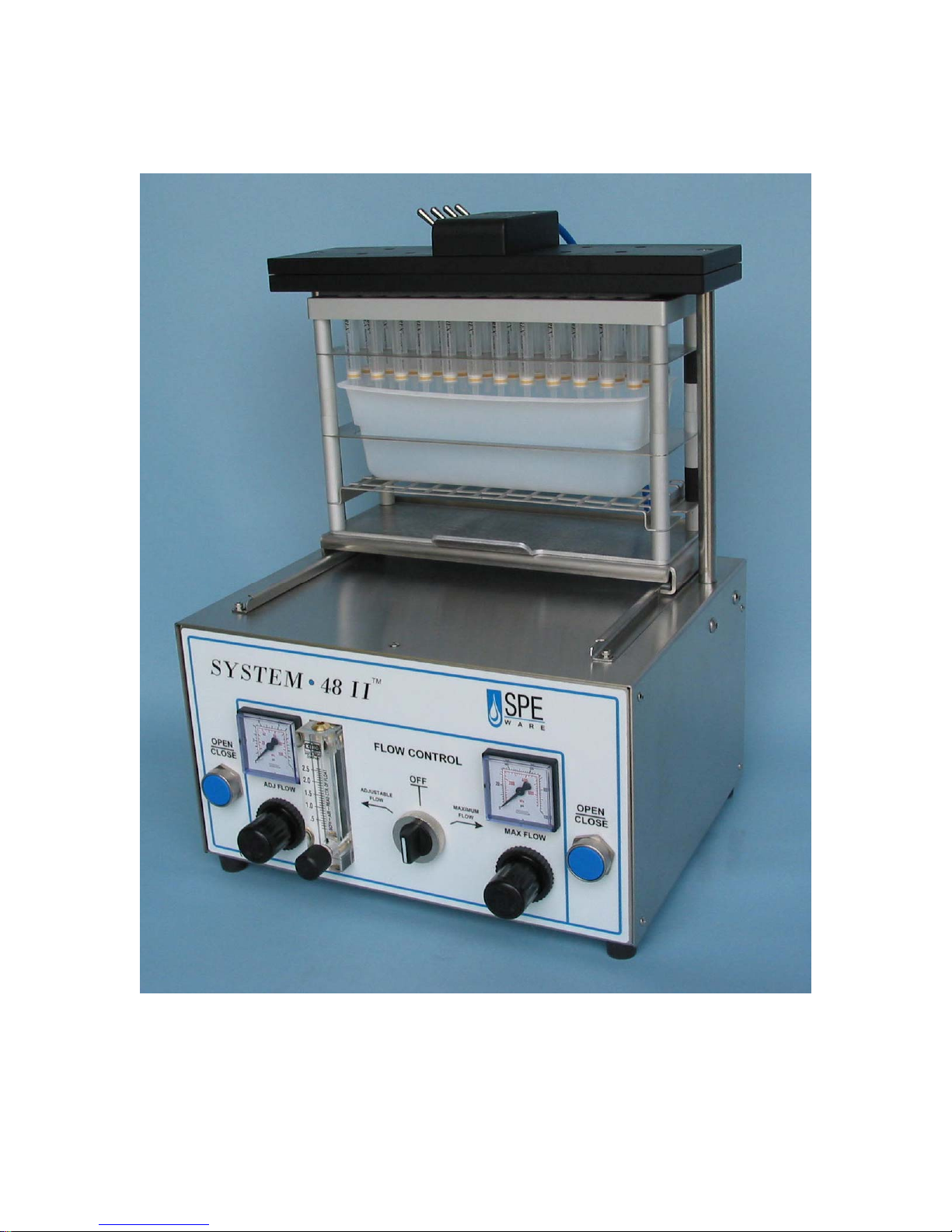
OPERATING INSTRUCTIONS
CEREX PRESSURE PROCESSOR
System
48-II
Page 2
Page 3

INSTALLATION
CAUTION
The SPE Processor does not include a filter on the source
gas input. A clean, oil-free gas source is essential to
prevent sample contamination.
Compressed nitrogen is the recommended pressure source in order to assure
inert atmosphere operation. If this is not a consideration, the unit can operate
using high purity filtered instrument air.
This instrument is supplied with an installation kit which includes 6 feet of 1/8”
i.d. (1/4” o.d.) polyethylene tubing and connectors to 1/8” NPT or 1/4” NPT.
Using the tubing and fittings provided connect the unit to a regulated oil free gas
source.
Optimum Source Pressure is 80 psig.
Min Pressure is 50 psig
Max Pressure is 100 psig
Page 4
SPE RACK CONFIGURATIONS and USE
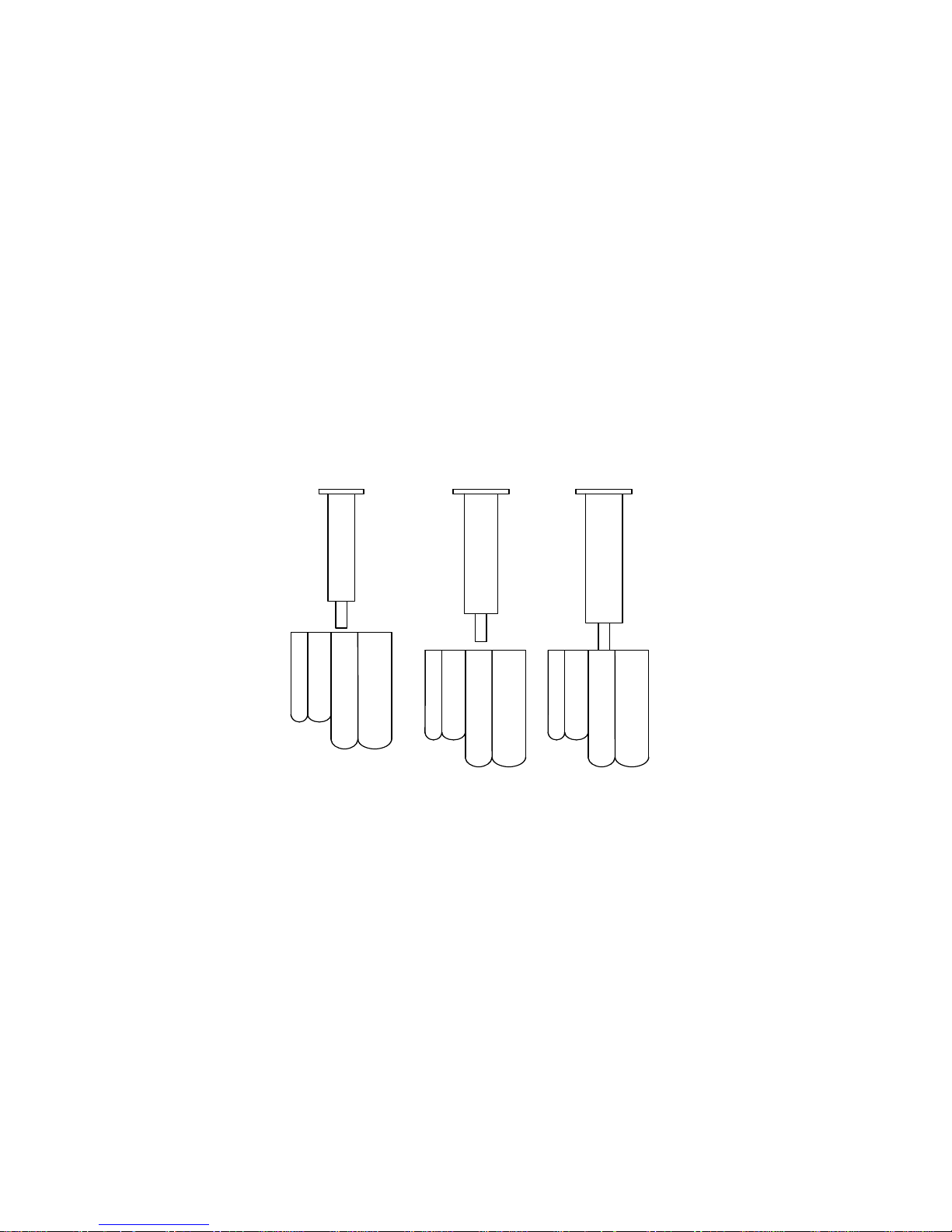
The System 48-II Pressure Processor provides the means to batch process solid
phase extraction columns in the 48-position format. The CEREX column racks
interface to several collection tube racks which are also in the 48-position format.
Depending upon the volume of the effluent, the appropriate collection rack can be
selected from the ancillary products available with the Pressure Processor.
The processor collection tube racks are optimally designed for 75mm or 125mm
high collection tubes. Ancillary collection racks are available to accommodate
common collection tube sizes (Auto sampler vial racks, 10x75, 12x75, 13x100, 13
x 125, 16 x 100 and 16x125). Contact customer service for further details and
availability of other sizes.
Standard SPE C olum n & Collection Tube Combinations...
10
x
75
1cc
12
x
75
13
x
100
16
x
100
3cc 6cc
12
10
x
75
x
75
13
x
100
16
x
100
12
10
x
x
75
75
13
x
100
16
x
100
The waste bin and tube racks are physically keyed to the platform by three
elevated pins on the platform that recess into the bottom of the rack. When
installed appropriately, the tub and rack should sit level on the platform.
System 48 column racks are keyed to the collection racks so that sample position
is preserved throughout the SPE sequence. The column rack is then positioned
directly on top of the waste bin or collection tray. Note that the When
appropriately placed, the stack should sit level on the platform. For each
extraction step, slide the platform toward the back until it stops on the guides.
All collection racks are compatible with the system 48 sample concentrator,
allowing for samples to be placed in the concentrator without the timely transfer
of samples from rack to rack.
Page 5

COLUMN COMPRESSION and DECOMPRESSION
The Processor is designed to accept up to 48 columns installed in the column
rack. Because of the unique manifold design, each column will be pressurized to
the same level even if columns are omitted. Refer to “Manifold Operation” in the
following section.
Assemble the appropriate collection rack and SPE column rack and position the
assembly on the System 48 Pressure Processor slide platform. Slide the
platform to the rear of the processor until it reaches the stop locating it under the
manifold.
The two blue push buttons used to activate the compression mechanism are
located on opposite sides of the front panel. Both push buttons must be pressed
at the exact same time to open or close the compression mechanism. Activate
the column compression mechanism by depressing the push buttons until the
manifold has stopped moving (2 to 3 seconds). If you let go too soon the manifold
mechanism will automatically open. This is a safety feature designed to keep your
hands clear of moving parts during the compression and decompression cycle.
Decompression of the rack assembly is activated similarly. Both push buttons
must be depressed simultaneously until the manifold has stopped moving. Slide
the rack assembly forward until it reaches the stop and proceed with the next
step of the SPE method.
The compression speed been pre-set and is not adjustable. The pressure applied
to the compression system has been pre-set and is not adjustable.
Page 6
MANIFOLD OPERATION
p
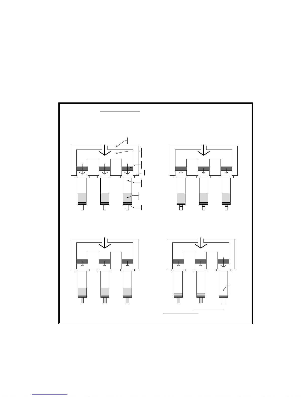
Each of the 48 holes in the Processor manifold are restricted in order to maintain
the manifold pressure even if all of the positions are not filled by columns. In
addition there are valves located on top of the manifold that shut off individual
rows of 12. With no column in place, there is approximately 0.75 +/- .05 scfh of
flow through a hole at 25 psig. The principle of the restrictor manifold design is
discussed in the following diagrams.
Po sitive P ressu re C o ntrol “w ith flow restrictors”
In itial s tate . M anifo ld p re ss u re b u ild s to
Fig A.
controller set pressure. The effect of the restrictors is
m in im al in lim iting flo w from m an ifo ld to c o lum n
reserv oir. R eserv o irs start at atm o sph eric p res sure .
manifold
block
30
psi
0
psi
manifold
pressure
chamber
gas flow
“res tricto r”
SPE column
rese rv oir
solvent or
sample fluid
30
psi
si
0
Input Pressure
P = 30psi
30
psi
0
psi
column seal
Sh o r tly a fte r th e in itia l sta te, th e p re ssu r e b u ild s in the
Fig B.
column reservoir due to the fluid being held up by the flow
ch a ra cte ris tics of th e c o lu m n so rb e n t b ed . R estr ictio n s till ha s
minimal effect. Eventually the pressure builds enough to
overcom e the fluid flow resistance and the fluid begins to
pass through the sorbent bed.
Input Pressure
P = 30psi
30
psi
24
psi
psi
psi
30
24
30
psi
24
psi
sorbent bed
Depending on flow characteristics of column
Fig. C.
sorb en t bed , pres sure in co lum n res erv oir stab ilizes.
Input Pressure
P = 30psi
30
psi
24
psi
Inh ibiting th e flow w ith th e co n stricto rs a t th is tim e is h elpfu l in tw o w a y s
minim ized as com pared to a system with no inhibitors. (2) the pressu re rem ains h igh
liquid as compared to the empty or dry columns.
30
psi
24
psi
30
psi
24
psi
W hen fluid passes through (one or more colum ns)
Fig. D.
co m ple te ly , an d th e re is m in im al p re ss u re d ro p ac ro s s th e
column bed, the effect of the restrictor is m axim ized. The
restrictor becomes the prim ary flow inhibitor of the gas as it
passes through the column to the atmosphere.
Input Pressure
P = 30psi
26
psi
18
psi
26
psi
18
psi
: (1) the amount of gas
in the colum n s containing
26
psi
10
psi
used is
empty
or dry
column
The manifold is segmented into 4 rows. Using the 4 toggle switches on the
manifold individual rows of 12 can be turned on or off to save nitrogen. The
adjustable flow reading on the rotometer equates to the total flow to the turned
on rows.
Page 7

EXTRACTION FLOW ADJUSTMENT
The System 48-II Pressure Processor has a two-level gas delivery system used to
pressurize the SPE columns.
One part of the system is controlled by the rotameter located on the left side of
the instrument panel. By switching the “SPE FLOW RATE” selector to the left,
“ADJUST FLOW” setting, the gas is delivered to the SPE Column Manifold
through the ADJ FLOW regulator and then thru the rotameter which is controlled
by the needle valve located at its base. The rotameter route provides a very
precise slow flow through the SPE columns by limiting the gas flow to the
manifold from 0 to 2.5 SCFH.
NOTE:
The rotometer needle valve is for adjustment only and is NEVER to be used as
an on off valve. Use the selector valve to turn off the nitrogen flow.
The second part of the gas delivery system provides for rapid gas flow to the
manifold which is controlled by adjusting the regulator located below the
pressure gauge labeled “MAX FLOW.” The pressure range is 0-80 psig and is
used to maximize flow through the SPE columns for processing viscous or high
particulate samples or to dry the columns in situ. By switching the “SPE FLOW
RATE” selector to “MAX FLOW”, gas is introduced to the manifold at the
pressure set on the “MANIFOLD PRESSURE” regulator as indicated by the gauge
located directly above it.
By turning the “SPE FLOW RATE” selector to off, no gas will flow to the manifold;
it should be in the off position when decompressing the column set between the
various SPE method operations.
Note that the regulator is of the “locking” type. The regulator can be adjusted by
pulling out on the regulator knob. Once the desired pressure is set, it can be
“locked in” by pushing in on the knob.
Page 8

MAINTENANCE
The System 48 Pressure Processor is a rugged unit constructed of anodized
aluminum, stainless steel and solvent resistant plastics. However, the following
items should be observed during operation:
1. Solvent spillage or overflow should be cleaned immediately in order to prevent
instrument damage.
2. The column seal is silicone rubber and can be cleaned with methanol.
WARRANTY
The System 48 Pressure Processor is warranted for 90 days. Warranty repairs
will be made given that the product has not been abused. It is constructed
primarily of stainless steel and anodized aluminum. Other materials include
silicone rubber, polyethylene and polypropylene. The controls and gauges are
not solvent resistant. Some components, including the column seal, may be
replaceable under the warranty. If there are any problems with the Processor
parts contact Customer Service at 626.814.2688 for further assistance.
Spare parts or replacements beyond the warranty period for such components as
waste bins, manifold seals, and plumbing items are available. Contact customer
service for current options and pricing.
Page 9
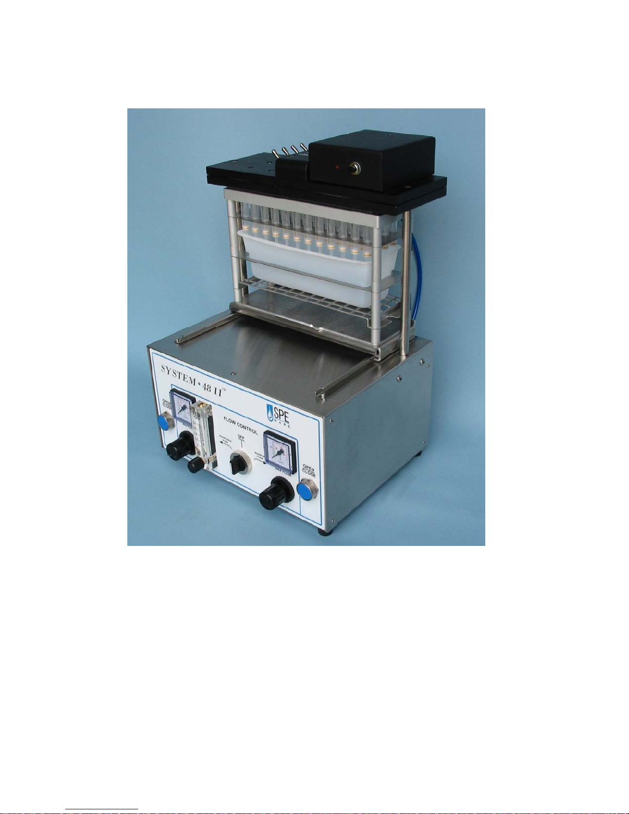
HEATED MANIFOLD OPTION
The Manifold Heater option provides heated gas flow through the sorbent bed
and assists in removing residual moisture. This in turn not only yields higher
analyte recovery, It also allows the sorbent bed to be eluted with a more selective
solvent like hexane or ethyl acetate. The result is an extract that is highly purified
and free of interferences.
The Manifold Heater operates on 110 VAC @ 13 amps.
The temperature is preset to 45 degrees Celsius and requires minimal heat up
time.
Page 10
Page 11
 Loading...