

Page 1

Installation Guide
Page 2

i-Watcher® is registered trademarks of Spetrotec LTD.
All other product or service names are the property of their respective owners.
© Spetrotec LTD, January 2015.
Page 3

Contents
General Description................................................................................ 1
Unpacking .............................................................................................. 4
Installation .............................................................................................. 5
Cautions.................................................................................................... 5
Tools and Service Aids............................................................................. 7
Installation Guidelines............................................................................... 8
Installing the SIM Card and Back-up Battery............................................ 10
Status LED Indications................................................................................... 13
System Connection Diagram.................................................................... 15
Setting the system to Arm/Disarm using the original car remote key..... 16
Post Installation Tests ............................................................................ 18
i
Page 4

Troubleshooting...................................................................................... 20
Specifications ......................................................................................... 22
ii
Page 5

General Description
i-Watcher® Cellular Alarm is a versatile and cost-effective GSM/GPS cellular
alarm and control unit that prevents stealing attempts and provides on-line
tracking capabilities for cars, trucks and motorbikes.
i-Watcher® Cellular Alarm unit utilizes the Global Positioning System (GPS) to
lock on vehicles coordinates and use the GSM cellular network for controlling
and monitoring the vehicle status by SMS or GPRS communication channels.
The smartphone application is a user friendly graphic interface that enables to
remotely control the i-Watcher® and receive essential information and alerts
from the vehicle.
The unit also incorporates interchangeable I/O ports to for flexible and most
effective interface to a vehicle.
The unit is designed to meet strict automotive standards for durability, power
consumption and temperatures.
1
Page 6

i-Watcher Cellular Alarm benefits:
• Enables to locate your vehicle in real time on an on-line map using a Smartphone application and offers Fleet Management and Control Application
(MABAT On-Line).
• Provide alerts on theft attempt, over speeding, towing, tilt, low battery and
battery cut off.
• Prevents ignition back in case of theft attempt.
• Enable to remotely Arm or Disarm the vehicle security system using one of
the following options:
• Original car remote keys
• Proximity card
• Wireless code remote
• Keypad on dash
• Smartphone application
2
Page 7

• GPRS or SMS based communication
• Firmware Over The Air (FOTA) update capability.
i-Watcher Cellular Alarm alerts and controls:
Alerts:
• Vehicle state (arm/disarm, alarm, driving)
• Vehicle position with time stamp
• Speed limit
• Ignition switch state (on/off)
• Low level of Vehicle battery Voltage
• Vehicle battery cut-off
• Tilt, towing
• Door open/close (only applicable for vehicle with doors)
3
Page 8

Controls:
• Remote arm/disarm
• Remote engine kill
• Remote siren activation
• Get status notifications
Important: The i-Watcher Cellular Alarm is designed to be customized to
operate in many modes and may have been programmed with additional features. For complete set of modes and features, contact your local dealer.
Unpacking
The i-Watcher Cellular Alarm kit includes the following items:
• i-Watcher Cellular Alarm unit
• 2 RF Proximity cards or 2 Wireless code remote for arming & disarming
when not using original remote keys.
• Installation harness
4
Page 9

• Back-up battery
• Fuse holder with a 2A fuse
• Installation guide (you are currently using it)
• Operation Guide
Important: To enable the operation of the i-Watcher Cellular Alarm unit, SIM
card is required. The SIM card is not provided with the i-Watcher Cellular
Alarm kit. To obtain a SIM card, contact your service provider or local dealer.
Installation
Cautions
• Do not install the i-Watcher Cellular Alarm unit in places that can hinder the
operation of air bags.
• Before installation, disconnect the negative cable of the vehicle battery and
remove the ignition key from the switch unless otherwise noted.
5
Page 10

• The i-Watcher Cellular Alarm unit must operate only in negative ground
electrical systems. Check the ground polarity of the vehicle before starting
the installation to verify that the polarity is correct.
• To check power in the vehicle, use only a power meter or a power probe
equipped with a LED. Do not use a filament bulb as a power tester. Using a
filament bulb may result in over current and cause severe damage to the
vehicle electronic systems.
• Plan wire and cable routing to provide maximum protection from overheating, battery acid, moving parts and sharp edges.
• Keep cables away from ignition circuits to reduce noise pickup from wireless
equipment.
• Hide and secure the i-Watcher Cellular Alarm unit under the dash of the car.
Wires should be routed through conduit/duct or along other electrical harnesses.
6
Page 11

• Do not route cables next to a fuel system or pipes.
• Do not locate cables where they can be tackled by the driver or passengers
or where they can interfere with the operation of the driver’s foot pedals.
• Ensure that the i-Watcher Cellular Alarm unit is kept away from water or
any other liquids.
• Always refer to local vehicle authority regulations and design rules.
Tools and Service Aids
The following tools and service aids are required for installation:
• Electrical screwdriver with Phillips bits
• Electrical drill with drill bits
• Cutters
• Wire isolation strippers
7
Page 12

• Soldering Iron
• LED power probe or power meter
• Isolation tape
• Plastic ties
Installation Guidelines
1. i-Watcher Cellular Alarm unit must be oriented parallel to the horizon, with
the Status LED (See “Status LED Indications” on page 13) set toward the
sky, to assure maximum visibility of the GPS satellites. The installation
location must not be obstructed by any metal structure.
2. To prevent unauthorized users tampering with system, hide and secure the
i-Watcher Cellular Alarm unit in a way that it will show as an original vehicle
component. The i-Watcher Cellular Alarm unit should not be visible and as
inaccessible as possible.
8
Page 13

3. Make sure all wires are solidly connected. Solder all wire connections and
isolate properly.
4. Connect the Green wire of the harness to an ignition switch terminal that
maintains +12/24V after ignition.
5. The Main Fuse (2A) should be located as close as possible to the power
source.
6. Install the i-Watcher Cellular Alarm unit far as possible from units emitting
radio frequency to avoid interference.
7. The ground wires (GND) must be connected to a solid chassis ground uninhibited by paint or plastics.
9
Page 14

Installing the SIM Card and Back-up Battery
Note: Before installing the SIM card inside the i-Watcher Cellular Alarm unit,
make sure that harness of the i-Watcher Cellular Alarm unit is disconnected from the unit.
Important: The SIM card is programmed with your subscriber number and
other information which enables the i-Watcher Cellular Alarm unit to register
with the GSM cellular network.
Before installing the SIM card inside the i-Watcher Cellular Alarm unit:
- Make sure to deactivate the PIN code of the SIM card, to prevent PIN protec-
tion lock.
- Use a mobile phone to make sure the SIM card can make and receive SMS
and phone calls without any problem.
- Before install the SIM card, use a mobile phone to empty all data storage
from the SIM card.
10
Page 15

To Install the SIM card & back-up battery:
1. Remove the screw and lift the Battery Compartment Cover.
2. Slide the SIM Card Holder to Unlock position.
Important: To avoid damage to the unit or SIM, do not install the SIM card
when the battery is connected.
3. Open the SIM Card Holder.
4. Slide the SIM Card into the SIM Card Holder with the contacts facing down.
Note the Card Notch position.
5. Close the SIM Card Holder and slide the SIM Card Holder to Lock position.
6. Connect the battery connector to the Battery Socket.
7. Make sure that the Status LED remains on steady for about 30 seconds
(unit in its’ initialize process).
8. Place the Back-up Battery in Battery Compartment.
9. Close the Battery Compartment Cover and secure the screw.
11
Page 16
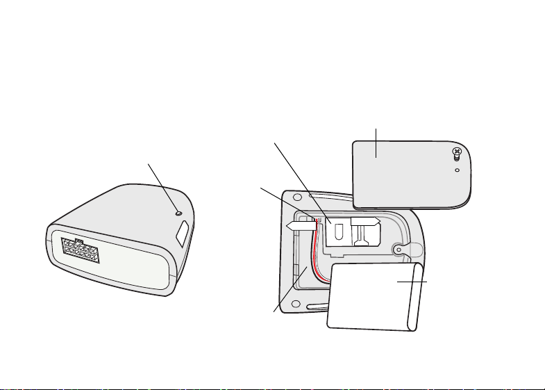
10. Make sure that the Status LED is blinking Red.
Battery Compartment Cover
Battery Compartment
Back-up
Battery
SIM Card Holder
Status LED
Lock
Unlock
Battery
Socket
After installing Back-up Battery, the unit needs few minutes to initialize and
retrieve information. During initialization, the Status LED shows Red.
12
Page 17

Following initialization, the Status LED displays the status of the i-Watcher
Cellular Alarm unit as detailed in following table (see “Status LED Indications”
on page 13).
Status LED Indications
When the back-up battery is connected to the unit, observe the Status LED to
determine if the unit operates properly. If the LED does not illuminate check the
back-up battery connection,
Status LED Indication Description
Red LED does not blink Vehicle power is disconnected or the unit is
in sleep mode
Red LED remains on steady i-Watcher initialization in progress (about 30
seconds)
Red LED blinks fast - 0.5
Normal operation
second on and 0.5 second off
13
Page 18
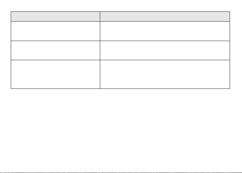
Status LED Indication Description
Red LED blinks fast twice
No GPS reception
every two seconds
Red LED blinks fast three
times every two seconds
No GSM registration. Check SIM card
installation and verify GSM coverage
Red LED blinks fast No GSM registration and no GPS reception.
Check SIM card installation and verify GSM
coverage. Move the vehicle to an open area
14
Page 19
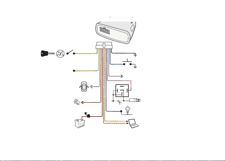
System Connection Diagram
30
87a
87
85
86
+
+
-
Input 4 - Ignition Switch (+15V)
+12/24 V Battery System
2A Fuse
Output 3 (-) 250mA
Note: Prefer this output if central door
Lock is used.
Output 1 - Buzzer DC (-) 250mA
i-Watcher Cellular Alarm Unit
Output 4 (-) 250mA
Note: Prefer this output if central
door Unlock is used.
+12/24V
RS232 Programming & Accessories
Com
Input 1 (-) Panic Button
GND
Door Input 3 (-)
Output 2 - Engine Cut off (-) 250mA
Input 2 - Blinkers (-) (See Note)
White/Orange (12) (TX)
White/Yellow (6)(RX)
Gray (3)
Pink (4)
Black (1)
Blue (2)
Green (11)
Yellow (10)
White
(9)
Orange (8)
Red (7)
Purple (5)
1
12
7
Note: If wireless code remote or proximity card is
connected, Input 2 blinkers should not be
connected.
Important: To connect a dashboard keypad, contact your dealer for parts and
connection diagram.
15
Page 20

Setting the system to Arm/Disarm using
the original car remote key
The i-Watcher Cellular Alarm System can be set to Arm/Disarm using the
original wireless remote control provided with the car remote key.
The system Arms or Disarms by counting the number of blinks received from
the car blinkers when he car doors are lock or unlock.
To set the system to Arm/Disarm using the original car remote keys, perform
the following:
To set the system to Arm/Disarm using the original car remote keys, perform
the following:
Important: Before starting this procedure, verify that the number of blinks is
different when the car locks and when unlocks.
1. Close the car doors.
16
Page 21

2. Continuously, switch the ignition key on and off five times - the last key
switch is followed by series of fast beeps. Wait about 20 seconds until a single beep is heard.
3. Press once on the ARM button of the car remote key and wait 3 seconds
until two fast beeps are heard.
4. Press once on the DISARM button of the car remote key and wait 3 seconds
until three fast beeps are heard.
5. Press once on the ARM button and wait 3 seconds until four fast beeps are
heard.
6. Press once on the DISARM button. A single long beep is heard.
Important: If three long beeps are emitted during the procedure, repeat the
procedure from step 1.
17
Page 22
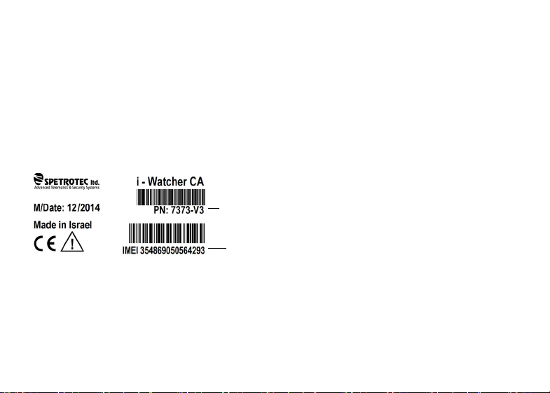
Post Installation Tests
Part Number
i-Watcher Cellular Alarm
Unit Identification Number
Before testing the i-Watcher Cellular Alarm unit, move the vehicle outside, so
that the unit can receive signals from the GPS satellites.
During testing, validation information may be required. Refer to the label
provided with your i-Watcher unit.
18
Page 23

The following tests should be performed and validated after installation by your
supervision and control center.
Verify the following:
• Status LED of the i-Watcher Cellular Alarm unit blinks fast red, once every
two seconds.
• Engine start/shutdown.
• Ignition switch on/off state detection.
• Vehicle location and movement detection.
• Input controls detection.
• Alarm, block engine and other output devices operation.
• Additional features operation (for details contact your dealer).
19
Page 24

Troubleshooting
Problem Cause Solution
Wireless code
remote or
Proximity Card or
Original car
remote key does
not work.
20
Depleted battery
inside Wireless Code
Remote or Proximity
Card or Original car
remote key.
1. Replace battery.
2. Use smartphone/iPhone
application or send SMS to
disarm the system (see
Operation Guide).
3. Perform Emergency neutralize
(see Operation Guide).
4. Contact Support Center/
Dealer.
Page 25

Problem Cause Solution
Vehicle location
cannot be
detected.
The i-Watcher
Cellular Alarm unit is
not receiving signals
Move the vehicle outside this
area and make sure that clear
sky can be viewed.
from the GPS
satellites.
No communication
with the vehicle
The unit is not
detecting the local
cellular system.
Poor signal strength from the
local cellular system. Move the
vehicle outside this area.
21
Page 26

Specifications
Dimensions
• Length 83 mm
• Width 71 mm
• Height 29 mm
Weight
• 82 gr (without interface cable)
Interfaces
• 4 digital input ports - 2 active low + 2 active high
• 4 digital output ports
• RS232 maintenance port
• 2.4 GHz wireless communication
22
Page 27

Electrical Characteristics
• Operating Voltage 12-24V DC
• RF receiver ON< 8.6mA
• Sleep mode < 2 mA
• Backup battery - Li-ion 3.7V/1000mAh
Communication Modes of Operation
Cellular mobile application (GPRS) or messaging based communication
(SMS)
GSM
• GSM Quad-Band: 850/900/1800/1900 MHz
• GPRS class 10
• On-board GSM quad band printed antenna - 50 Ohm
• Integrated SIM card holder
23
Page 28

• 3G - optional
GNSS
• Internal GPS Module based on 56-channel (U-Blox) Max 7 Engine
• GPS/QZSS L1 C/A, GLONASS L1 FDMA
• SBAS: WAAS, EGNOS, MSAS
• Accuracy GPS / GLONASS position of 2.5m CEP/4.0 m
• SBAS 2.0 m CEP
• Sensitivity: -162 dBm/-158 dBm
• GPS-GLONASS Internal antenna
Alerts
• Over speeding
• Tow and Tilt
• Door status (vehicle applicable)
24
Page 29

• Battery cut-off and low power level
• Ignition state (ON/OFF)
• Vehicle state (Arm, Disarm, Alarm, Driving)
• Position and Last Time Stamp
• Alerts can be simultaneously sent to two cellular phones
• Controls by mobile application or SMS
• Remote arm/disarm
• Remote "prevent ignition back"
• Remote siren activation
• Get status
Operating Temperature
o
C to +85oC
-30
25
Page 30

Miscellaneous
• Red LED indicator
• Built in 3D G sensor
Enclosure
• Nonflammable PC-ABS
• IP-67 version - optional
Optional Accessories
• RF proximity card for driver identification or wireless remote controls - 2
units per i-Watcher cellular alarm unit.
• Dashboard Keypad
• Normal arm/disarm is done by original vehicle RF - original keys
26
Page 31

Page 32

5 Mavo Kedem St. Industrial Area Gil Amal. Hod Hasharon 45317 ISRAEL
+972.9.743.4555 +972.9.742.3666
WWW.SPETROTEC.COM [email protected]
 Loading...