

Sperry Marine Visionmaster FT ECDIS User Manual
ECDIS User Guide
© Northrop Grumman Sperry Marine B.V.
Part Number: 65900012


ECDIS User Guide
Part Number: 65900012-12
Publication Revision : A
Software Version : 10.0
Before using the equipment, please read this manual.
© 2017 Northrop Grumman Sperry Marine B.V.
This publication and the information contained herein is and remains the intellectual
property of Northrop Grumman Sperry Marine B.V. Northrop Grumman Sperry
Marine B.V. provide a limited licence for the user to reproduce this material for their
own internal purpose and use, but not for distribution to third parties. Reproduction
of this material for resale or commercial gain is expressly prohibited. Northrop
Grumman Sperry Marine B.V. are not responsible for any loss or damage of any
nature or kind whatsoever that may arise from either the use of this publication or its
reproduction.

ECDIS User Guide
Intentionally Blank
65900012 iii

ECDIS User Guide Warnings and Cautions
Warnings and Cautions
The features, functionality and capability which are described in this
manual are not necessarily present in all versions or configurations of the
VisionMaster FT system.
WARNING: Lethal Voltage Hazard
WHEN ACCESS COVERS ARE REMOVED, LETHAL VOLTAGES MAY BE
EXPOSED. SOME CAPACITORS USED IN THE EQUIPMENT TAKE
SEVERAL MINUTES TO DISCHARGE THEIR STORED VOLTAGES AFTER
SWITCH OFF; THIS IS A LETHAL VOLTAGE HAZARD. ALWAYS SET THE
SUPPLY SWITCH-FUSE TO OFF AND REMOVE THE FUSES, BEFORE
REMOVING THE ACCESS COVERS OF THE EQUIPMENT.
WARNING: Health Hazard
WHEN CLEANING THE INSIDE OF THE EQUIPMENT, TAKE CARE NOT
TO INHALE DUST. THE DUST IS A TEMPORARY HEALTH HAZARD,
DEPENDING ON INDIVIDUAL ALLERGIES.
WARNING: Radiation Hazard
KEEP OUTSIDE THE HAZARD ZONE AROUND AN ANTENNA OR OPEN
WAVEGUIDE RADIATING POWER. REFER TO THE TABLE BELOW FOR
HAZARD ZONES. WHEN IT IS NECESSARY TO WORK ON THE SCANNER
UNIT, MAKE SURE THAT RADAR IS SWITCHED OFF, AND THAT BOTH
THE MAINS ISOLATOR AND THE SCANNER CONTROL UNIT ARE
TURNED TO THE OFF POSITION.
NEVER LOOK DIRECTLY INTO AN OPEN WAVEGUIDE.
RADAR AND OTHER FORMS OF RF RADIATION CAN CAUSE CARDIAC
PACEMAKERS TO MALFUNCTION. IF YOU USE A CARDIAC
PACEMAKER AND SUSPECT A MALFUNCTION, LEAVE THE VICINITY OF
THE RADAR SYSTEM IMMEDIATELY AND SEEK MEDICAL ADVICE.
Most countries accept that there is no significant radiation hazard at RF
power density levels of up to 100W/m
65900012 iii
2
(10mW/cm2).

Warnings and Cautions ECDIS User Guide
Hazard Zones
Antenna Length 100 W/m2 50 W/m2
1.2 m X-Band 1.7 m 8.5 m
1.8 m X-Band 1.05 m 5.25 m
2.4 m X Band 0.75 m 3.75 m
2.7 m S-Band 0.73 m 3.65 m
3.7 m S-Band 0.55 m 2.75 m
10 W/m2
17 m
10.5 m
7.5 m
7.3 m
5.5 m
CAUTION: Electrostatic Sensitive Devices (ESSDs)
This equipment contains ESSDs. Take care not to damage these
devices by discharge of electrostatic voltages.
CAUTION: Anti-Virus Protection
Before connecting an external device such as a USB memory
stick, or external media such as a CD or DVD to the VisionMaster
PC it is important that the external de vice/media should first be
scanned with a recognised virus and mal ware scanning program
that includes up-to-date virus definitions. Also, the external
device/media should be reserved for use with VisionMaster PCs,
with use on other computers kept to an absolute minim um.
VMFT USB ports must be used only for operati on al data transfer,
not for other purposes e.g. USB charging.
Care should be taken to ensure that any PCs (e.g. laptops) that
have been previously connected to other networks are subject to
the same checks as external media prior to being connected to
the network on which VisionMaster PCs are connected.
iv 65900012

ECDIS User Guide Preface
PREFACE
ABOUT THIS MANUAL
The structure of this manual and the design of the pages can help you to
find the information that you need. Consistent presentation techniques are
used throughout the manual, to make it easy to use.
Depending on the composition and configuration of your
installation, not all of the facilities presented in this User Guide may
be applicable to your system.
This manual is intended to be used by the VisionMaster FT operator and is
divided into the following chapters, appendices and annexes:
Chapter 1 - Overview
Chapter 2 - Getting Started with ECDIS
Chapter 3 - Basic Operation of ECDIS
Appendix A - Operational Functions specific to
Multi-node and Client/Serv er S ystems
Chapter 4 - Charts
Appendix A - Chart Datum Codes
Chapter 5 - Navigation Tools
Chapter 6 - Sensor Management
Chapter 7 - Alerts
Chapter 8 - Routes
Chapter 9 - Electronic Range and Bearing Lines
Chapter 10 - Targets
Chapter 11 - Radar
Chapter 12 - Brilliance
Chapter 13 - System
Annex A - Static Site
Your system may include optional features or purchased features that are not described in this manual. For information on these optional features, refer to Supplementary Features User Guide, 65900014.
65900012 v

Preface ECDIS User Guide
NOTICE
Northrop Grumman Sperry Marine (“NGSM”) products may include factory installed
software. By use of such product/s the user explicitly agrees and accepts the terms
and conditions contained within the NGSM End User License Agreement.
The EULA is available to view in the Ships Manual Volume 2, (65900011V2)
Introduction.
Northrop Grumman Sperry Marine B.V. has a policy of continuous development.
This may lead to the equipment described in this manual being at variance with
equipment manufactured after its publica t io n.
Industry Recommendations for ECDIS Training
Ship owners and operators should provide crews with a comprehensive
familiarisation program based on the IMO Model Course on ECDIS (1.27).
This training is recommended even when ECDIS is used on vessels to
which SOLAS and IMO STCW (Standards of Training, Certification and
Watchkeeping) do not apply.
Ship owners and operators should always refer to their national
Administrations for the latest regulations governing ECDIS carriage and
use.
vi 65900012

ECDIS User Guide Table of Contents
Table of Contents
Warnings and Cautions ................................................................... iii
PREFACE ................................................................................................ v
Industry Recommendations for ECDIS Training .............................. vi
Overview ................................................................... 1-1 Chapter 1
Hardware Configurations.............................................................. 1-1
Single System .............................................................................. 1-2
Interswitched System ................................................................... 1-4
Multi-Node System ....................................................................... 1-6
Dual Radar – Single System ........................................................ 1-7
Dual Radar – Interswitched System ............................................. 1-8
Dual Radar Features .................................................................... 1-9
Client Server Radar System ........................................................1-10
Product Types .............................................................................1-11
ECDIS Common Features ...........................................................1-12
Optional Features .......................................................................1-15
Purchasable Features .................................................................1-16
Radar Overlay Features ..............................................................1-17
Total Watch .................................................................................1-18
Information on Sensor Inputs to the System ................................1-19
Compass Input ................................................................................... 1-19
Log Input ............................................................................................. 1-19
Position Input ...................................................................................... 1-19
Getting Started with ECDIS ..................................... 2-1 Chapter 2
System Controls ........................................................................... 2-2
Control Panel ........................................................................................ 2-2
Monitor Controls ................................................................................... 2-4
Power On/Off ........................................................................................ 2-4
System Start-Up ........................................................................... 2-5
Switching on the System ...................................................................... 2-5
Software Start-Up ................................................................................. 2-6
Setup Procedures ................................................................................. 2-7
System Security ........................................................................... 2-9
65900012 vii

Table of Contents ECDIS User Guide
ECDIS Screen Layout ................................................................. 2-10
Main Menu and Sub Menu Area ......................................................... 2-10
Upper and Lower Toolbar Areas ........................................................ 2-11
Screen Layout for Widescreen Display .............................................. 2-11
Chart Display .............................................................................. 2-12
Accessing System Functions ...................................................... 2-13
Upper Toolbar Functions .................................................................... 2-13
Lower Toolbar Functions .................................................................... 2-14
Main Menu and Sub Menu Functions ................................................. 2-15
Accessing Context Window from the Display ..................................... 2-16
Controlling Popup Windows ........................................................ 2-17
Show/Hide Windows ........................................................................... 2-17
Using the Cursor ......................................................................... 2-18
Cursor Graphics.................................................................................. 2-18
Standby and Transmit Mode ....................................................... 2-20
Standby Mode ..................................................................................... 2-20
Transmit Mode .................................................................................... 2-21
Standby/Transmit Mode in Dual Radar .............................................. 2-21
Online Help ................................................................................. 2-22
Accessing Context Sensitive Help ...................................................... 2-22
Accessing the Help Guide .................................................................. 2-22
On-Screen Keyboard .......................................................................... 2-23
Accessing Tool Tips.................................................................... 2-23
Operator Messages .................................................................... 2-24
Action Required Messages ................................................................. 2-24
Operator Messages ............................................................................ 2-24
System Shut Down ..................................................................... 2-25
Basic Operation of ECDIS ....................................... 3-1 Chapter 3
Selecting Transmit Mode .............................................................. 3-2
Selecting Transmit Mode in an Interswitched System.......................... 3-2
Selecting Transmit Mode in a Client Server Radar System ................. 3-3
Dual Radar – Transmit Selection .......................................................... 3-3
Returning to Standby Mode .......................................................... 3-4
Heading Line, Beam Line and Stern Line...................................... 3-5
Beam Line ............................................................................................. 3-6
Own Ship Symbols ....................................................................... 3-7
viii 65900012

ECDIS User Guide Table of Contents
Outline Symbol ..................................................................................... 3-7
Custom Symbol .................................................................................... 3-7
Own Ship Vector ................................................................................... 3-8
Predicted Vector ................................................................................... 3-9
Cursor Readout ...........................................................................3-10
Position .......................................................................................3-12
Alert Status Indicator ...................................................................3-15
Alert Status ......................................................................................... 3-15
Sensor Data Display ...................................................................3-16
Stabilisation Options ........................................................................... 3-17
Multi-node System .............................................................................. 3-17
Presentation Modes ....................................................................3-18
North Uniformity .................................................................................. 3-19
Presentation Mode dictated by Raster Charts ................................... 3-19
Motion Modes .............................................................................3-20
True Motion ........................................................................................ 3-20
Vector Modes ..............................................................................3-21
Selecting the Vector Mode ................................................................. 3-21
Vector Time ........................................................................................ 3-23
Radar Overlay Mode ...................................................................3-24
Switching the Radar Overlay On ........................................................ 3-24
Setting Radar Overlay Transparency Levels...................................... 3-24
Radar Overlay Settings ...................................................................... 3-25
Dual Radar – Radar Overlay Control ................................................. 3-25
Scale Ratio .................................................................................3-26
Automatic Scale .................................................................................. 3-26
Manual Scale ...................................................................................... 3-27
Zoom Window ..................................................................................... 3-27
Chart Database & Chart Sub Menu Selection .............................3-29
Target Display Button ..................................................................3-31
AIS Display Button ......................................................................3-32
Access to Own Ship AIS..................................................................... 3-32
Messages ...................................................................................3-33
ECDIS Presentation Options .......................................................3-34
Picture in Picture Mode ...................................................................... 3-34
Split Screen Mode .............................................................................. 3-34
Functions Available in Secondary Chart Windows ............................. 3-35
65900012 ix

Table of Contents ECDIS User Guide
Off Centre, Pan and Goto ........................................................... 3-36
Off Centring Own Ship ........................................................................ 3-36
Panning ............................................................................................... 3-37
Goto .................................................................................................... 3-37
Centre & Maximum View Options ............................................... 3-40
Centring .............................................................................................. 3-40
Maximum View ................................................................................... 3-40
True Motion Limits ...................................................................... 3-41
Displaying the TM Limits .................................................................... 3-41
Setting the TM Limits .......................................................................... 3-41
Re-sizing the TM Limits box ............................................................... 3-43
Current Date and Time ............................................................... 3-44
Range Rings ............................................................................... 3-45
Brilliance Control ........................................................................ 3-46
Profiles ....................................................................................... 3-46
Zoom Window............................................................................. 3-47
Scale Bar .................................................................................... 3-48
Watch Mo de ............................................................................... 3-49
Total Watch Features ......................................................................... 3-50
Display Base .............................................................................. 3-51
Display Chart .............................................................................. 3-52
Pick Report ................................................................................. 3-53
Safety Checking ......................................................................... 3-54
Highlight Indicators ............................................................................. 3-55
Multi-node Support ............................................................................. 3-57
Print Screen ................................................................................ 3-57
Alternate Bow ............................................................................. 3-58
CID Windows .............................................................................. 3-59
Bearing to Wheelover ......................................................................... 3-59
Steering Mode & Route INFO ............................................................. 3-59
Docking Display .................................................................................. 3-61
HUD Widgets ...................................................................................... 3-61
Appendix A - Operational Functions specific to Multi-node and
Client/Server Systems ..................................................................... 1
Station in Control ..................................................................................... 1
Database Synchronization ....................................................................... 1
x 65900012

ECDIS User Guide Table of Contents
Charts ....................................................................... 4-1 Chapter 4
Accessing Charts Menus.............................................................. 4-2
International Hydrographic Organization (IHO) Standards and
Compliance .................................................................................. 4-3
About Charts ................................................................................ 4-4
Chart Types .......................................................................................... 4-4
Chart Rendering ................................................................................... 4-4
Factors affecting Chart Accuracy ......................................................... 4-5
Chart Overscale .................................................................................... 4-6
Larger Scale Available Prompt ............................................................. 4-7
Chart Safety Information....................................................................... 4-7
Chart One Presentation Library ............................................................ 4-7
Using Raster Charts ..................................................................... 4-8
Description ............................................................................................ 4-8
Selecting Raster Charts........................................................................ 4-9
Chart Tools .................................................................................4-11
Tool Functions ............................................................................4-13
Chart Match ........................................................................................ 4-13
Chart Information ................................................................................ 4-14
Chart Installation .........................................................................4-24
Importing Charts ................................................................................. 4-24
Chart Copy ..................................................................................4-28
View Logs ........................................................................................... 4-30
Permissions / User Permits .........................................................4-31
Chart Settings .............................................................................4-34
Settings Functions.......................................................................4-35
Layers ................................................................................................. 4-35
Symbology .......................................................................................... 4-36
AIO Data ............................................................................................. 4-41
ECDIS Standard Default Settings ................................................4-43
Chart Projections ........................................................................4-44
Effect of Projections ............................................................................ 4-44
Projection Types ................................................................................. 4-44
Chart Depths/Heights ..................................................................4-46
Ship Safety ......................................................................................... 4-46
Shallow and Deep Shading ................................................................ 4-47
Changing Chart Depth/Height Values ................................................ 4-47
65900012 xi

Table of Contents ECDIS User Guide
Chart Databases ........................................................................ 4-48
Enabling and Disabling Databases..................................................... 4-48
Enabling AUTO Scale Preferences .................................................... 4-49
Supported Chart Engines and Chart Databases ................................ 4-49
Official and Unofficial Chart Data ....................................................... 4-50
Chart Legend .............................................................................. 4-51
Chart Information at a Specific Point .................................................. 4-51
Legend Select ..................................................................................... 4-52
Legend Detail ...................................................................................... 4-53
Legend Update Review ...................................................................... 4-56
Notes .................................................................................................. 4-56
Manual Update ........................................................................... 4-57
Multi-node Support ............................................................................. 4-57
Manual Update Functions ........................................................... 4-58
Layers ................................................................................................. 4-58
Edit ...................................................................................................... 4-59
Create and Modify Manual Updates ................................................... 4-59
Modify Chart Update ........................................................................... 4-70
Display Chart Updates ........................................................................ 4-72
Archived .............................................................................................. 4-74
Report Query Features ............................................................... 4-75
Report Results .................................................................................... 4-75
Report Options.................................................................................... 4-77
Chart Dangers ............................................................................ 4-78
Danger List ......................................................................................... 4-79
Dangers Information ........................................................................... 4-80
Danger Settings .................................................................................. 4-80
Chart 1 ....................................................................................... 4-84
Chart 1 Catalog................................................................................... 4-84
Color Diagram ..................................................................................... 4-85
Tides/Currents ............................................................................ 4-86
Appendix A Chart Datum Codes ...................................................... 1
Navigation Tools ..................................................... 5-1 Chapter 5
Parallel Index Lines ...................................................................... 5-2
Description ............................................................................................ 5-2
Multi-node Support ............................................................................... 5-2
Edit Parallel Index Lines ....................................................................... 5-2
Display Parallel Index Lines ................................................................. 5-8
xii 65900012

ECDIS User Guide Table of Contents
Importing and Exporting PI Lines ......................................................... 5-9
Clearing Lines .............................................................................5-10
Editing Clearing Lines......................................................................... 5-10
Monitoring Clearing Lines ................................................................... 5-16
Import/Export Clearing Lines .............................................................. 5-17
Line Of Position ...........................................................................5-19
Creating LOPs .................................................................................... 5-20
LOP Fixes ........................................................................................... 5-22
Using a LOP Position Sensor ............................................................. 5-23
Optional Optical Bearing Sensor (OBD) ............................................. 5-24
Ownship History ..........................................................................5-25
Primary History Track ......................................................................... 5-25
Position Sensor Tracks....................................................................... 5-26
History................................................................................................. 5-26
Changing History Settings .................................................................. 5-28
Event Marks ........................................................................................ 5-28
Parallel Cursor ............................................................................5-29
Trial Manoeuvre ..........................................................................5-31
Adjusting Trial Manoeuvre Parameters .............................................. 5-31
Delay Countdown ............................................................................... 5-32
Displaying the Trial Manoeuvre .......................................................... 5-32
Display of Vectors ............................................................................... 5-33
Trial Manoeuvre Vector ...................................................................... 5-34
Trial CPA and TCPA ........................................................................... 5-34
Distance Line ..............................................................................5-35
Display Settings Features ...........................................................5-37
Display Settings .................................................................................. 5-37
Ownship .............................................................................................. 5-37
Next Turn EBL .................................................................................... 5-42
Grid ..................................................................................................... 5-43
Anchoring ....................................................................................5-44
Anchoring Description ........................................................................ 5-44
Anchoring Planning ............................................................................ 5-45
Anchoring Display ............................................................................... 5-49
Anchoring Status ................................................................................ 5-51
Man Overboard ...........................................................................5-53
Navigation Marks ........................................................................5-57
Sensor Management ................................................ 6-1 Chapter 6
65900012 xiii

Table of Contents ECDIS User Guide
Sensors Menu .............................................................................. 6-1
Sensor Data Source ............................................................................. 6-2
Primary Sensors on ECDIS Systems ............................................ 6-4
Sensor Data Sources .................................................................... 6-5
Heading Source Values ........................................................................ 6-5
STW Source Values ............................................................................. 6-6
COG Source Values ............................................................................. 6-7
SOG Source Values ............................................................................. 6-8
Position Values ..................................................................................... 6-9
Depth Source Values .......................................................................... 6-12
Set and Drift Values ............................................................................ 6-13
Rate of Turn Values ............................................................................ 6-14
Date and Time .................................................................................... 6-14
Wind Values ........................................................................................ 6-14
Alerts ........................................................................ 7-1 Chapter 7
Alerts ..................................................................................................... 7-1
Prompts ................................................................................................ 7-2
Alert Status Indicator .................................................................... 7-3
Alert Status ........................................................................................... 7-4
Alert Display ................................................................................. 7-5
Viewing Alert Details ............................................................................. 7-6
Hide Acknowledged .............................................................................. 7-6
Sort by Group ....................................................................................... 7-6
Alert Buzzer .................................................................................. 7-7
Alerts on a Multi-node System ...................................................... 7-8
Alerts on a Client/Server Radar System........................................ 7-8
Alert Behaviour Specific to ECDIS ................................................ 7-9
Prompts ...................................................................................... 7-10
Permanent prompts ............................................................................ 7-10
Temporary Prompts ............................................................................ 7-10
Prompts Window................................................................................. 7-10
Mute Settings ............................................................................. 7-11
Central Alert Management .......................................................... 7-12
Picture Freeze ............................................................................ 7-13
List of Alarms, Warnings and Cautions ....................................... 7-13
List of Alarms and Warnings specific to Client/Server Radar ............. 7-35
xiv 65900012

ECDIS User Guide Table of Contents
Routes ...................................................................... 8-1 Chapter 8
Routes ......................................................................................... 8-3
Multi-node Support ............................................................................... 8-4
Creating a Route .......................................................................... 8-5
Adding a Waypo i nt ............................................................................... 8-5
Changing a Waypoint's Position ........................................................... 8-7
Delete a Waypoint ................................................................................ 8-8
Changing a Waypoint's Turn Radius .................................................... 8-8
Editing a Route ............................................................................ 8-9
Edit Route ............................................................................................. 8-9
Route Tab Folder ................................................................................ 8-10
Waypoints Tab Folder ........................................................................ 8-15
Dangers .............................................................................................. 8-21
Critical Points ...................................................................................... 8-23
Editor Table ........................................................................................ 8-26
Monitoring a Route ......................................................................8-30
Monitor Route ..................................................................................... 8-30
Route .................................................................................................. 8-31
Dangers .............................................................................................. 8-36
Critical Points ...................................................................................... 8-37
Speed Planning ...........................................................................8-38
Speed Planning Setup ........................................................................ 8-38
Monitoring Speed Planning ................................................................ 8-43
ETA Calculator ............................................................................8-44
Route ETA ..................................................................................8-46
Required Speed ..........................................................................8-47
Route Status ...............................................................................8-48
Temporary Routes ......................................................................8-49
Creating and Editing a Temporary Route ........................................... 8-49
Monitoring a Temporary Route ........................................................... 8-50
Transitioning a Temporary Route to a Monitored Route .................... 8-51
Search and Rescue .....................................................................8-52
Creating SAR Patterns ....................................................................... 8-53
External Routes ..........................................................................8-57
Multi-node Support ............................................................................. 8-58
Importing and Exporting a Route .................................................8-59
Importing Routes ................................................................................ 8-59
Exporting Routes ................................................................................ 8-60
65900012 xv

Table of Contents ECDIS User Guide
Route Display Settings ............................................................... 8-61
Electronic Range and Bearing Lines ..................... 9-1 Chapter 9
Creating an ERBL ......................................................................... 9-2
Changing the ERBL Bearing ................................................................ 9-3
Changing the ERBL Range .................................................................. 9-3
Off-Centring, Carrying and Dropp ing an ER BL .................................... 9-4
Dropping an EBL/VRM on the Displa y ................................................. 9-6
Variable Range Marker (VRM) ...................................................... 9-7
Targets ................................................................. 10-1 Chapter 10
Tracking Targets ......................................................................... 10-2
Target Data received from TLB Sentence .......................................... 10-2
Tracking Targets on a Multi-Node System ......................................... 10-2
Cancelling Targets on a Multi-node System ....................................... 10-3
Tracking Targets on a Dual Radar System ........................................ 10-3
Tracked Targets Capacity .................................................................. 10-4
AIS Targets ................................................................................ 10-5
AIS Rendering Conditions .................................................................. 10-5
AIS Target States ............................................................................... 10-5
AIS Target Display Capacity ............................................................... 10-8
Active AIS Target Capacity ................................................................. 10-8
Target Alert States .............................................................................. 10-9
AIS Safety Messages ....................................................................... 10-10
Multi-node Support for AIS Targets .................................................. 10-10
Classes and Types of AIS ........................................................ 10-11
Target Monitoring ..................................................................... 10-13
Lost Target ........................................................................................ 10-13
CPA/TCPA and BCR/BCT Infringement Conditions ......................... 10-13
Target Monitoring Symbols ............................................................... 10-14
Multi-Node Support ........................................................................... 10-15
Selected Target Functions ........................................................ 10-16
Target Data ....................................................................................... 10-16
AIS INFO .......................................................................................... 10-18
Multiple Targets ........................................................................ 10-22
Automatic Sorting of Targets ............................................................ 10-22
Selecting Targets for the User Folder............................................... 10-23
Viewing Target Data from Multiple Targets ...................................... 10-23
Target Display .......................................................................... 10-24
xvi 65900012

ECDIS User Guide Table of Contents
Target Display .................................................................................. 10-24
Identification ..................................................................................... 10-25
Past Position Dots ............................................................................ 10-25
AUTO Drop Targets .......................................................................... 10-25
Other ................................................................................................. 10-25
Number of Targets ............................................................................ 10-25
AUTO Drop Targets .......................................................................... 10-27
AIS Display ............................................................................... 10-29
Settings All Nodes ............................................................................ 10-29
Filter Setting s .................................................................................... 10-30
AIS Target Information ..................................................................... 10-34
Other ................................................................................................. 10-34
Set All AIS Targets to Sleeping ........................................................ 10-35
Target Count All Nodes .................................................................... 10-35
Test Tracked Targets ................................................................ 10-36
Fixed Test Targets ............................................................................ 10-37
Moveable Test Targets ..................................................................... 10-38
Using Test Targets ........................................................................... 10-39
Using Test Targets as a Training Exercise ...................................... 10-40
Test Tracked Targets on Dual Radar ........................................ 10-41
Test Targets on Client/Server Radar ......................................... 10-42
Activation Zones ....................................................................... 10-43
Annular Activation Zones ................................................................. 10-44
Polygonal Activation Zones .............................................................. 10-46
Own Ship AIS ............................................................................ 10-47
Own Ship .......................................................................................... 10-47
Own Ship AIS Messages........................................................... 10-49
Message Tx ...................................................................................... 10-49
Message Rx ...................................................................................... 10-51
Limits and Settings .................................................................... 10-52
1) Collision Avoidance ...................................................................... 10-52
2) Target Association ........................................................................ 10-52
3) Lost Target Alerts ......................................................................... 10-52
Enablement and lost target range limit settings ............................... 10-52
Closest Point of Approach & Bow Crossing Limits ........................... 10-53
Target Association ............................................................................ 10-53
Lost Target Alerts ............................................................................. 10-54
Collision Avoidance Criter ia ............................................................. 10-54
PADs......................................................................................... 10-55
65900012 xvii

Table of Contents ECDIS User Guide
Radar .................................................................... 11-1 Chapter 11
Radar Settings ............................................................................ 11-2
Transceiver ........................................................................................ 11-2
Operational Mode ............................................................................... 11-2
Pulse Length ....................................................................................... 11-3
Tune .................................................................................................... 11-3
Dual Radar – Transceiver ........................................................... 11-5
Radar Overlay ............................................................................ 11-6
Video Processing Controls ................................................................. 11-6
Trails ................................................................................................... 11-9
Dual Radar – Video .................................................................. 11-10
Interswitch ................................................................................ 11-11
Request for Display .......................................................................... 11-11
Interswitch on Dual Radar ........................................................ 11-12
Interswitch on Client/Server Radar ........................................... 11-13
Disconnecting and Reconnecting a Client ........................................ 11-13
Radar Alerts ............................................................................. 11-14
Video Alerts ...................................................................................... 11-14
Communications Alerts ..................................................................... 11-14
Transceiver Alerts ............................................................................. 11-15
Brilliance .............................................................. 12-1 Chapter 12
Day and Night Modes ................................................................. 12-2
Multi-node Settings ............................................................................. 12-2
Brilliance Groups ........................................................................ 12-3
Chart Symbols ............................................................................ 12-4
Brightness Check ....................................................................... 12-5
System ................................................................. 13-1 Chapter 13
User Profiles ............................................................................... 13-2
Multi-Node Functionality ..................................................................... 13-2
Create New Profile.............................................................................. 13-3
Available Profiles ................................................................................ 13-4
Viewing or Editing Profiles .......................................................... 13-5
View/Edit Profile – Selection ............................................................... 13-5
View/Edit Profile – Editing .................................................................. 13-7
Options ....................................................................................... 13-8
xviii 65900012

ECDIS User Guide Table of Contents
Diagnostic Functions ...................................................................13-9
Diagnostics ......................................................................................... 13-9
Performance Monitor ........................................................................ 13-10
Report ............................................................................................... 13-12
Detail Log ......................................................................................... 13-14
Sensor Status ................................................................................... 13-16
Connection Status on a Multi-Node System..................................... 13-20
Connection Status on a Client/Server Radar System ...................... 13-21
Buzzer............................................................................................... 13-21
Database .......................................................................................... 13-21
Dual Radar – Diagnostic Functions .................................................. 13-22
Commissioning Functions ......................................................... 13-23
Authorization ..................................................................................... 13-25
Config Update ................................................................................... 13-27
Characteristics .................................................................................. 13-29
Service .............................................................................................. 13-30
Time Management .................................................................... 13-34
Local Offset ...................................................................................... 13-34
Shutdown .................................................................................. 13-35
Annex A - Static Site .................................................................... 1
Static Site Description ...................................................................... 1
Static Site Features .......................................................................... 1
Features specific to a Static Site ............................................................. 1
Features not available to a Static Site ..................................................... 2
Wide Screen Monitors on Static Site ....................................................... 2
Static Heading .................................................................................. 3
Heading Line ........................................................................................... 3
Static Position .................................................................................. 4
Target Anchor Watch ....................................................................... 5
Target Based Range and Bearing .................................................... 7
Trusted Targets ................................................................................ 8
Trusted Target List .................................................................................. 8
Range Limit ............................................................................................. 9
Adding a Trusted Target .......................................................................... 9
Removing a Trusted Target ................................................................... 10
65900012 xix

Table of Contents ECDIS User Guide
xx 65900012

ECDIS User Guide Overview
Overview Chapter 1
Hardware Configurations
The VisionMaster FT system consists of the following hardware
configurations:
• A single node system, comprising one console connected to a
transceiver, antenna and turning unit (collectively known as a
Scanner Unit), see Si ng le S ystem .
• An interswitched system, with each console connected via an
Interswitch to separate Scanner Units, see Interswitched System.
• A multi-node system, where consoles, configured to specific
product types, are connected via a LAN, see Multi-Node System.
• A single node dual radar system, comprising one console
connected to two Scanner Units, see Dual Radar Single System.
• An interswitched system, with a combination of dual radars and
single radars, connected via a six way Interswitch to Scanner
Units, see Dual Radar I nter s witc hed System.
• A Client /Server Radar (CSR) system where one or more servers
provide radar video over a network for display at Client nodes,
see Client Server Radar System.
On conventional radar systems radar video and other radar/chart radar
sensor data is output directly from the PCIO to the console (monitor and
1
. On a CSR system data is output from the PCIO to the Server unit
PC)
before the data is supplied on request to Client nodes via an Ethernet
network.
Traditional bridge equipment and most navigation sensors can be
interfaced to a VM FT system. On a CSR system Client nodes can
provide master or slave displays at any required location.
1
On VM FT systems that require no radar (for example, ECDIS without radar overlay or
Conning INFO Display) a PCIO is not required. Data can be received over a network
connection.
65900012 1-1
Overview ECDIS User Guide
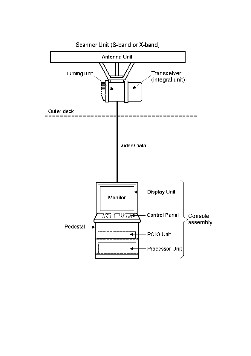
Single System
1-2 65900012

ECDIS User Guide Overview
Scanner Assembly2. Comprises an Antenna unit, a Turning unit and an
optional Performance Monitor. If the system includes an integral
transceiver then this also forms part of the Scanner Assembly. If the
system uses a bulkhead transceiver then the transceiver unit is not
included in the Scanner assembly.
Antenna Unit. 10cm S-band (9 or 12ft aperture) or 3cm X-band (4,
6 or 8 ft aperture).
Performance Monitor. If fitted, the performance Monitor Antenna
is mounted on the Turning Unit.
Transceiver. Masthead (mounted as an integral part of the
Scanner assembly) or Bulkhead (mounted as a separate unit below
decks).
Scanner Control Unit – for switching the scanner on and off – are
supplied for S-band radars only.
Console Assembly - supplied as a standalone 250 tabletop and 340
tabletop/deck mounted console (including pedestal); or a kit version for
installation into an existing console suite. The 250/340 console assembly
includes the following modules:
Input/Output (PCIO) Unit - receives data inputs from the
transceiver and external sensors; outputs data to the processor
unit.
Processor Unit - a single PC running Windows XP operating
system.
Display Unit - includes a flat panel monitor
Control Panel - There are two types of control panel: Basic and
Enhanced. The basic control panel only includes a trackball with
left and right keys. The enhanced control panel includes the
following additional group of controls: Rotary controls and
Adjustment & Acknowledgement buttons.
The console assembly may also be supplied as a 19" Integrated Tabletop,
where the Monitor, PCIO, Processor and control panel are all contained in
a single mechanical housing.
2
A Scanner assembly may also be referred to as a `Top Unit'.
65900012 1-3
Overview ECDIS User Guide
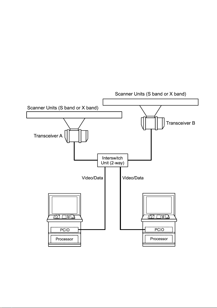
Interswitched System
The basic, single-scanner/single-console configuration can be expanded
by the introduction of an Interswitch Unit, plus additional scanners and
display configurations. The arrangement below shows two scanners (S
band or X band), two transceivers (A and B) with a two-way inters witc h
unit connected to two consoles. A 6-wa y inters witch unit is available for
systems with a maximum of six scanners and six consoles.
A console may be connected via the interswitch to any one of the scanner
units, and can be selected as the master display, or as a slave display.
1-4 65900012

ECDIS User Guide Overview
A console selected as a master display has full control of the connected
scanner. The controls available at a master display but NOT at a slave
display are as follows:
• switching the transceiver between standby and transmit mode
• selection of transmission pulse-length
• tuning the transceiver
• selecting Manual or AFC mode for tuning
• tuning the performance monitor.
65900012 1-5
Overview ECDIS User Guide
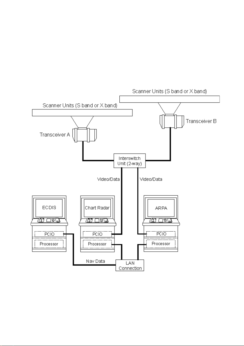
Multi-Node System
A multi-node system may include a number of consoles which have been
configured as specific product types, see Watch Mode.
Each console is linked via a LAN so that data input to one console is
available to all. Consoles providing radar video data will be connected via
the interswitch to one or more scanner units, and can be selected as the
master display, or as a slave display.
1-6 65900012
ECDIS User Guide Overview
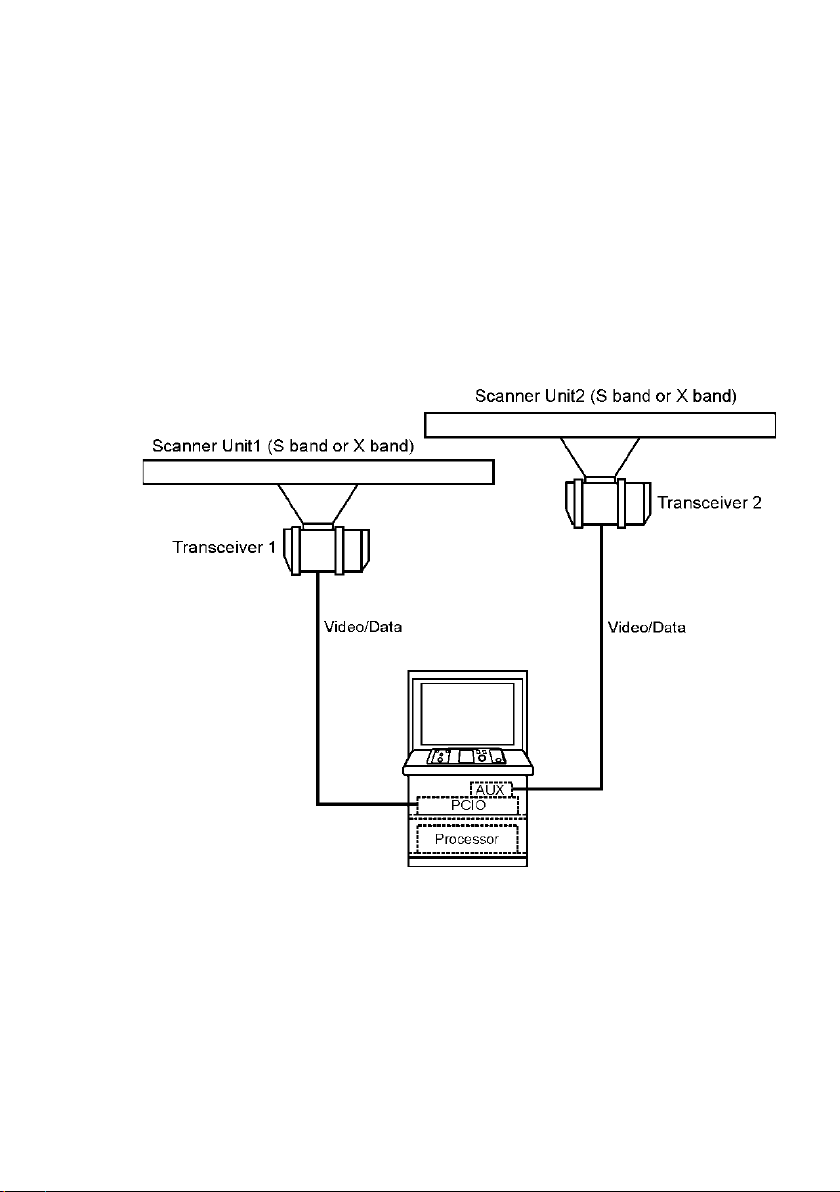
Dual Radar – Single System
A dual radar system can connect to two scanner units at the same time,
enabling the overlay of radar video from both scanners to form a
composite display. Each radar video source is known as a `Channel’.
A dual radar system includes an additional scan converter card and an
auxiliary PCIO unit.
For an overview on features specific to dual radar, see Dual Radar
Features
65900012 1-7
Overview ECDIS User Guide
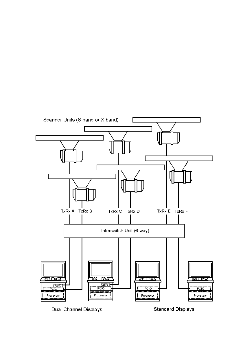
Dual Radar – Interswitched System
On an interswitched system a display radar channel can be associated
with any one of the scanner units in the system. A scanner unit can be
selected from its associated display as a Master radar channel for
controlling that scanner, or as a Slave radar channel if another display
radar channel has been selected as the Master.
The Master/Slave status of all display radar channels, and their specific
scanner couplings, can be monitored from any display unit in the system.
The figure below shows two dual channel displays with two standard
displays, connected to a 6-Way Interswitch unit.
1-8 65900012
 Loading...