

Sperry Marine 5016-CA, 5016-CB, 5016-CC, 5016-CD Operation, Installaion And Service Manual
Operation, Installation and Service Manual
Original Documentation / Keep for Future Reference
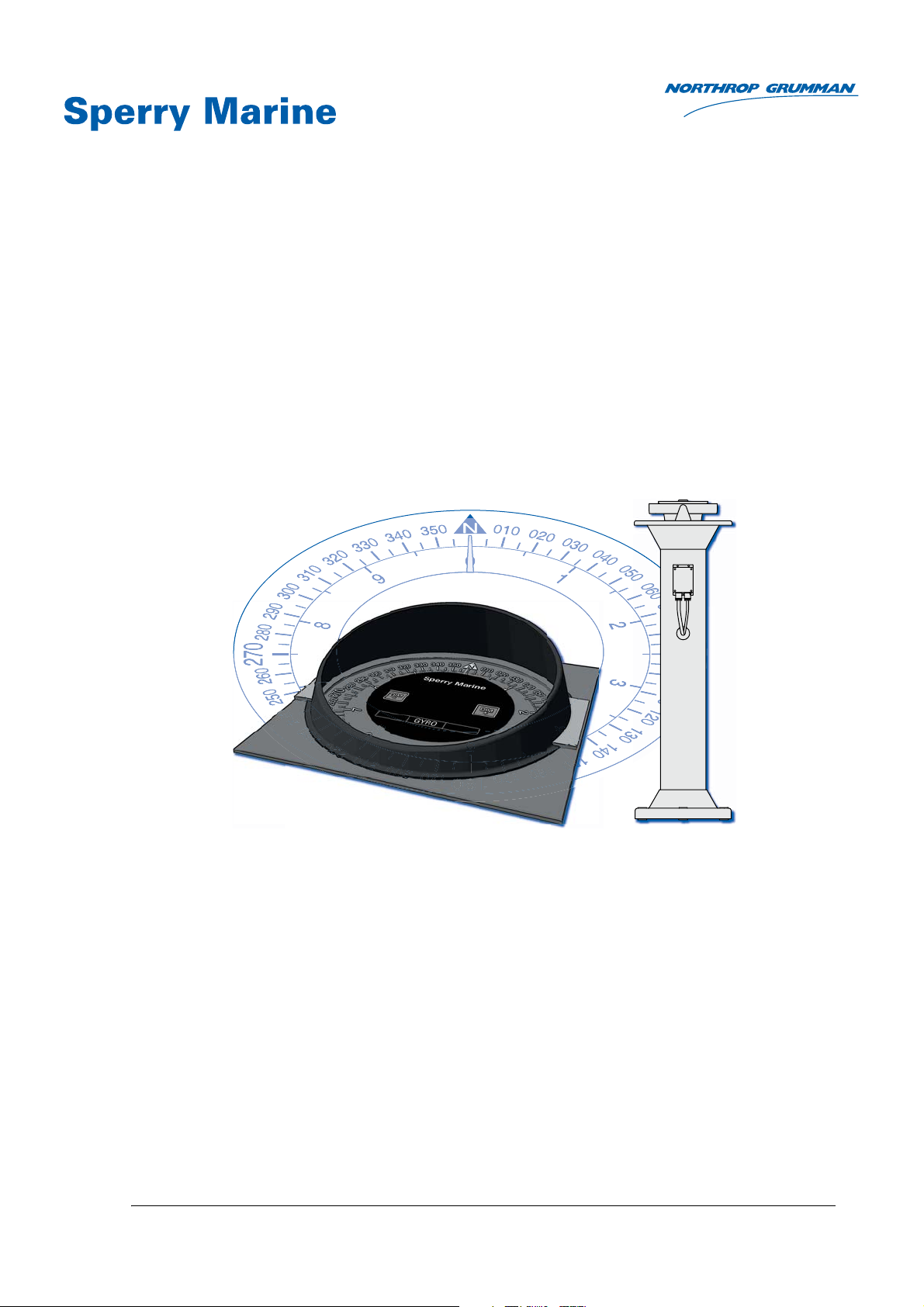
Analogue Compass Repeaters
Types 5016-CA, 5016-CB, 5016-CC, 5016-CD
with RS-422 Serial Interface
056376/A; 05016-0128-02, 03 Feb 2015
Northrop Grumman Sperry Marine B.V. (Representative Office)
Woltmanstr. 19 • D-20097 • Hamburg, Germany
Tel.: +49-40-299 00-0 • Fax: +49-40-299 00-146 • E-mail: service.eu@sperry.ngc.com

056376/A Analogue Compass Repeaters
© 2015 Northrop Grumman Sperry Marine B.V.
This document and the information herein is the intellectual property of Northrop Grumman
Sperry Marine B.V. [NGSM BV] and it’s associate companies and may not be copied, reproduced
or translated without the express permission of NGSM BV.
Specifications were correct at time of press but may be varied in accordance with NGSM BV’s
policy of continuous product development.
Any technical content should be verified with NGSM BV.
Sperry Marine, with major engineering and support offices in New Malden, England, and
Hamburg, Germany, is part of the Northrop Grumman Navigation & Maritime Systems Division
N&MSD.
Rev. Date Remarks
A 03 Feb 2015 Initial release; this manual applies for the analogue compass repeaters
types 5015-CA, -CB, -CC and -CD.
Manual 056359 remains valid for the now discontinued types
5016, 5016-AA, -AB and -AC.

Analogue Compass Repeaters 056376/A
Contents
Safety Instructions
Safety Notice Conventions ....................................................................... vii
General Safety Information for the Operator ........................................ viii
General Safety Information for Service Personnel ................................... x
Chapter 1: Introduction
1.1 System Description................................................................................... 1-1
Intended Use ............................................................................................. 1-1
Not Intended Use ...................................................................................... 1-1
1.2 Design and Main Features........................................................................ 1-2
1.3 Functional Description.............................................................................. 1-3
1.4 Compass Repeater Type Variants ............................................................ 1-4
Bearing Repeater....................................................................................... 1-4
Steering Repeater...................................................................................... 1-4
Magnetic Heading Repeater ..................................................................... 1-4
Bulkhead Repeater .................................................................................... 1-5
1.5 Accessories ................................................................................................ 1-5
Bearing Repeater Stand and Brackets ..................................................... 1-5
Bulkhead Repeater Bracket....................................................................... 1-5
Connection Box ......................................................................................... 1-6
Azimuth Device PV 23 ............................................................................... 1-6
Telescopic Alidade..................................................................................... 1-6
1.6 Technical Data............................................................................................ 1-7
1.7 Declaration of Conformity ...................................................................... 1-15
Chapter 2: Operation
2.1 Readout Elements, Indicators and Controls ........................................... 2-1
2.2 Powering up the Repeaters ...................................................................... 2-2
2.3 Data Protocol and Source Detection ....................................................... 2-2
2.4 Reading off Heading and Source Indication ........................................... 2-3
2.5 Adjusting the Illumination Brightness .................................................... 2-4
2.6 Synchronizing the Compass Cards.......................................................... 2-5
2.7 Initiating the Self Test............................................................................... 2-5
2.8 Bearing Repeater Capacitive Keys ........................................................... 2-5
2.9 Taking Bearings with the Azimuth Device PV 23 ................................... 2-6
Chapter 3: Error Indication
3.1 Error Blink Codes....................................................................................... 3-1
Heading Timeout with flashing Source Indicator................................... 3-2
iii

056376/A Analogue Compass Repeaters
Chapter 4: Preventive Maintenance
4.1 Maintenance by Shipboard Personnel .................................................... 4-1
Maintenance of externally installed Bearing Repeater .......................... 4-2
Chapter 5: Installation
5.1 Bearing Repeater....................................................................................... 5-1
Installing Bearing Repeater with Bearing Stand ..................................... 5-1
Installing Bearing Repeater with Bearing Bracket ..................................5-4
Installing Bearing Repeater with Adjustable Bearing Bracket ............... 5-6
5.2 Steering Repeater / Magnetic Heading Repeater .................................. 5-8
5.3 Bulkhead Repeater .................................................................................. 5-10
Chapter 6: Configuration
6.1 Using the Default Configuration .............................................................. 6-1
6.2 Configuring the Analogue Repeater with SUSI...................................... 6-1
6.3 Configuration Parameters ........................................................................ 6-6
RCS Type .................................................................................................... 6-7
Protocol Type ............................................................................................. 6-8
Baudrate..................................................................................................... 6-8
Gyro Selection ........................................................................................... 6-9
Magnetic Selection .................................................................................... 6-9
Status Selection....................................................................................... 6-10
Dimming Selection .................................................................................. 6-10
Dimming Group ID .................................................................................. 6-10
Dimming Offset ....................................................................................... 6-11
6.4 Dimming Values ...................................................................................... 6-12
Adjusting Dimming Values ..................................................................... 6-12
Serial Dimming Command Evaluation .................................................. 6-13
Chapter 7: Troubleshooting
7.1 Basic Service Checks ................................................................................ 7-1
All repeater types 5016-CA, -CB, -CC, -CD ............................................... 7-1
All repeaters, except bearing repeater, type 5016-CA ............................ 7-2
7.2 Viewing Error Information in SUSI .......................................................... 7-3
Analogue Repeater Error Page ................................................................. 7-3
Error IDs and Descriptions........................................................................ 7-4
7.3 Location of Parts on the Analogue Repeater PCB.................................. 7-6
Terminal Boards and Connectors............................................................. 7-7
Diagnostic LEDs......................................................................................... 7-7
Chapter 8: Corrective Maintenance
8.1 Updating the Repeater’s Firmware.......................................................... 8-1
Update Procedure...................................................................................... 8-2
iv

Analogue Compass Repeaters 056376/A
Abbreviations
Appendix
A Setup and Configuration Tables
B Drawings
v

056376/A Analogue Compass Repeaters
vi
Analogue Compass Repeaters 056376/A
DANGER
WARNING
CAUTION
Note
DANGER
CAUTION
Safety Instructions
Safety Notice Conventions
The following safety notice conventions are followed throughout this
manual:
A Danger notice contains an operating or maintenance procedure, practice, condition, statement, etc., which, if not strictly observed, will
result in injury or death of personnel.
A Warning notice contains an operating or
maintenance procedure, practice, condition,
statement, etc., which, if not strictly observed,
could result in injury or death of personnel.
A Caution notice contains an operating or maintenance procedure, practice, condition, statement, etc., which, if not strictly observed, could
result in damage to, or destruction of equipment.
A Note contains an essential operating or maintenance procedure, condition or statement,
which is considered important enough to be
highlighted.
Special safety symbols may be used in this
manual to indicate:
Danger: Risk of electrical shock.
Caution: Components are sensitive to electro-
static discharge.
vii
056376/A Analogue Compass Repeaters
WARNING
WARNING
WARNING
WARNING
WARNING
Note
General Safety Information for the Operator
Risk of Deviation
Never rely on the heading indication of an analogue compass repeater
alone to navigate a vessel or to perform other safety-critical operations.
The analogue repeater is an indicator only and will indicate ship’s heading as long as it receives formally valid data. It does not apply any filtering or plausibility checks of the incoming data.
Loss of data supply will result in a visual error indication but will not
raise an audible alarm.
Always confirm the plausibility of the heading indication at the repeater
against the respective source which generates the heading data.
In safety-critical operations, regularly check the data source and the
repeater’s indication against all available aids to navigation.
Risk of using magnetic heading data for steering
The magnetic heading repeater is equipped with a removable cover, hiding the compass card when navigating the vessel under normal use, as
the magnetic heading repeater is only classified for steering purposes in
case of emergency with other heading sources not available.
Never remove the cover from the magnetic heading repeater when navigating the vessel under normal use, to avoid steering the vessel mistakenly by magnetic compass heading.
Risk of using invalid heading data
The heading indication at the repeater is only valid if the error indicator
is off and exactly one of the source indicators is permanently lit.
In case the error indicator in on and one or all of the source indicators
are flashing the heading indication of the repeater must be considered
as invalid and the heading data must not be used for steering the vessel.
Risk of injury
Permanent eye damage may result, when looking directly at the sun or
at its reflection in the black azimuth mirror when using the azimuth
device PV 23.
The PV 23 is not suited for taking the azimuth of the sun itself, as the
anti-glare filters do not sufficiently block out direct sunlight.
Never look directly at the sun or at its reflection in the black azimuth mirror when using the azimuth device PV 23.
Risk of freeze
The bearing repeater 5016-CA is equipped with capacitive keys, sensitively reacting to the fingers skin resistance which will not function
when touched with gloves.
In case of minus temperatures always be extremely careful not to touch
the metal housing of the bearing repeater to avoid freeze of hands and
fingers.
viii
The capacitive keys of the bearing repeater 5016-CA are sensitive against
surface water, e.g. remaining rain drops, which may result in random
changing of the illumination brightness.
This effect does not have any impact on the functionality or handling of
the capacitive keys.
Analogue Compass Repeaters 056376/A
CAUTION
CAUTION
CAUTION
CAUTION
CAUTION
Note
Note
Risk of damage though solar radiation
The bearing repeater 5016-CA is equipped with a cover plate for protection against solar radiation.
It is recommended to always protect the bearing repeater with the cover
plate when not in use.
Risk of damage
The cover plate, protecting the bearing repeater 5016-CA against solar
radiation, must never be touched with tools to avoid any damage.
Always install and remove the cover plate with bare hands only.
Risk of damage through wrong cleaning agent
The front plates of the compass repeaters are sensitive against aggressive cleaning agents as organic solvents or acetone.
Do not clean the front plate with organic solvents, acetone or any other
aggressive cleaning agent.
Use only water and soap or a mild detergent to clean the front plate.
Risk of unnecessary wear
The bearing repeater 5016-CA can optionally be equipped with a watertight plastic cover for protection against environmental conditions.
It is recommended to always protect the bearing repeater with the plastic
cover when not in use.
Risk of damage
The prismatic azimuth device PV23 and the telecopic alidade are not
designed to stay permanently mounted on the bearing repeater.
Leaving the PV23 or the alidade on the bearing repeater after usage, will
cause wear and damage to the equipment.
Always remove the PV23 or the alidade from the bearing repeater and
store it carefully away in its storage box.
The repeater compasses do not possess an audible alarm indicator.
Sperry Marine Service:
In case of service refer to www.sperrymarine.com/offices for a list of
all Sperry Marine Offices and Service Agents worldwide.
ix
056376/A Analogue Compass Repeaters
CAUTION
CAUTION
CAUTION
CAUTION
CAUTION
CAUTION
CAUTION
General Safety Information for Service Personnel
Risk of wrong installation
Wrong positioning of the bearing stand will obstruct to take bearings.
Always make sure that the bearing stand is so positioned that the vessel’s superstructure does not unduly obstruct the view of the horizon.
In case one bearing stand does not allow to take bearings in a full circle
of 360°, a second bearing stand must be installed for compensation.
Risk of damage
The compass repeaters are heavy instruments. The compass repeater
cables are not designed for holding the repeater just with the cable.
Never hold or transport the repeater on the cable alone when installing
or wearing a compass repeater.
Risk of damage
The bearing repeater is a heavy instrument.
To avoid any damage during installation of the bearing repeater into the
gimbal ring, the installation should be carried out by two service persons.
Risk of malfunction
Do not lengthen the cable between the bulkhead repeater and the connection box as the USB service port will not work reliably.
If the connection box cannot be installed at an accessible location close
to the repeater, it will be required to unmount and disassemble the
repeater to gain access to the internal USB receptacle when configuring
or servicing the device.
If the repeater cable is connected directly to shipside terminals, the external USB port may not be used and its four wires must be connected to
blind terminals.
Risk of damage through unauthorized service
The housing of the bearing repeater 5016-CA is designed for increased
watertightness and shall therefore not be opened in the field.
Opening the housing in the field will diminish the watertightness and
may lead to condensation forming on the inside surfaces, especially the
top glass, at a later point in time.
Never open the bearing repeater housing in the field.
Always return a defective bearing repeater to Sperry Marine.
Risk of damage through unauthorized service
The analogue compass repeaters are complex electronic devices, which
are not serviceable in the field down to the level of individual circuit components.
Defective units must be sent back to Sperry Marine for repair.
x
Risk of damage of electrostatic-discharge-sensitive components
The analogue compass repeaters contain electrostatic sensitive components. Electrostatic discharge may permanently damage components.
When servicing an analogue compass repeater, take precautions to prevent electrostatic discharge. Avoid touching any of the electronic circuitry.

Analogue Compass Repeaters 056376/A
CAUTION
Note
Note
Risk of parameter settings loss
It cannot be guaranteed that the repeater’s configuration parameter settings are left intact during a firmware update.
Before updating firmware, record all parameter settings to be able to reenter them manually, if required.
The analogue compass repeaters are serviced and configured using the
Sperry Universal Setup Instrument (SUSI).
This tool is provided to authorized service personnel only and is generally not available to end-customers.
Exact voltage levels must be checked with a voltmeter true RMS.
The data content on serial I/O lines must be checked with the aid of suitable analysing tools, such as PC-based protocol interpreters or terminal
programs.
xi

056376/A Analogue Compass Repeaters
xii

Analogue Compass Repeaters 056376/A
Chapter 1: Introduction
1.1 System Description
Intended Use
The analogue compass repeaters are remote heading indicators which
display ship’s heading (secondary heading data), provided by a connected gyrocompass as active heading source (primary heading data),
and must only be operated from appropriately trained and educated
personnel familiar with all mandatory safety and operating procedures.
The prismatic azimuth device PV23 is a classified compass bearing
device designed for usage together with the bearing repeater 5016-CA.
Not Intended Use
The analogue compass repeaters are not allowed to be used for the navigation of inland water vessels and river boats. Any exception to this
restriction must be regulated by specific certification of an entitled
organisation or administration, for further details see certification information under ‘Design and Main Features” on page 1-2 and ‘Declaration
of Conformity” on page 1-15.
The magnetic heading repeater, type 5016-CC, is only classified for steering purposes in case of emergency when the gyrocompass(es) as primary heading source(s) are not available and must not be used for
navigating the vessel under normal conditions.
The telescopic alidade, stock no 60280, is not type approved as compass
bearing device, therefore it cannot be used to fulfil the carriage requirements.
System Description 1-1

056376/A Analogue Compass Repeaters
1.2 Design and Main Features
The analogue compass repeaters are remote heading indicators which
display ship’s heading (secondary heading data), provided by a connected gyrocompass as active heading source (primary heading data),
using a rotating compass card assembly.
The repeaters are available in four type variants:
• Bearing Repeater, Type 5016-CA
• Steering Repeater, Type 5016-CB
• Magnetic Heading Repeater, Type 5016-CC
• Bulkhead Repeater, Type 5016-CD
The analogue compass repeaters have been type-approved by Germanischer Lloyd (GL), in accordance with the Maritime Equipment Directive
(MED) 96/98/EC as amended, as
gyrocompass accessory equipment
in the type approval certificates of the
Sperry Marine gyrocompass systems
NAVIGAT X MK 1 (certificate no. 94418-10HH, 94428-10HH),
NAVIGAT X MK 2 (certificate no. 94420-10HH),
NAVIGAT 2100 (certificate no. 94416-10HH, 94426-10HH)and
NAVIGAT 3000 (certificate no. 37757-12HH, 37957-12HH).
The analogue compass repeaters comply with the following specified
standard as gyrocompass accessory equipment:
IMO resolution MSC.116(73).
For further details see “Declaration of Conformity” on page 1-15.
Heading data is received at an RS-422 serial data input, using the
NMEA 0183/IEC 61162 or the Plath binary protocol. The repeaters are
able to auto-detect the input data protocol and baudrate at power-up
and will self-synchronize with the input heading received.
Depending on the currently active heading source, the repeaters will
indicate true heading from a gyrocompass (GYRO), or a transmitting
heading device (THD1), or magnetic compass heading (raw or corrected
for deviation and/or variation) from a magnetic compass (MAG). The
active source is constantly highlighted at the repeater by a backlit indicator (“GYRO, “THD” or “MAG”).
Graduations and numbering of the cards’ scales appear white on a
matte black background. The cards are backlit by dimmable white LEDs.
A set of dimmer push buttons is integrated into the repeater front plate
of the steering repeater, type 5016-CB, magnetic heading repeater, type
5016-CC and the Bulkhead Repeater, type 5016-CD whereas the bearing
repeater, type 5015-CA, is designed with a new glass front and capacitive dimmer keys instead.
All repeater variants feature a 360° and a 10° compass card, except for
the magnetic heading repeater, where the 10° card is not assembled.
1. In the context of this manual, “THD” refers to a transmitting heading device
according to IMO MSC.116(73) or IEC 22090 parts 1-3 respectively.
1-2 Design and Main Features

Analogue Compass Repeaters 056376/A
The magnetic heading repeater, type 5016-CC, is preconfigured to indicate magnetic compass heading only, regardless of which source is currently active.
The magnetic heading repeater is equipped with a removable cover, hiding the compass card when navigating the vessel under normal use, as
the magnetic heading repeater is only classified for the indication of
magnetic heading data in case of emergency when the gyrocompass(es)
as primary heading source(s) are not available and the vessel is actually
steered by magnetic compass heading.
1.3 Functional Description
The compass card assembly is driven through a gear train by a stepper
motor. To ensure smooth and silent operation, the microprocessorized
motor control uses micro stepping. Photo interrupters detect when the
compass cards pass their zero positions at 360° and every 10°, respectively, allowing minor step losses to be automatically corrected during
operation.
Once valid heading data is received, the heading to be indicated is translated into a counter value representing the required compass cards’ offset from the North (zero) position. A second counter is maintained for
the cards’ current offset.
The motor control constantly executes a routine to minimize the difference between these two offsets, thus making the compass cards followup to the heading to be indicated.
The position of the cards is held in non-volatile memory, so that it is not
normally required to zero (re-synchronize) the cards upon power-up.
Functional Description 1-3

056376/A Analogue Compass Repeaters
Note
1.4 Compass Repeater Type Variants
Bearing Repeater
The bearing repeater, type 5016-CA, is gimbal-mounted for usage in a
bearing stand or in a repeater bracket attached to a bulwark. The bowlshaped watertight housing with new glass front permits installation at
exposed locations. The new capacitive keys of the bearing repeater front
increase additionally the watertightness of the housing.
The capacitive keys of the bearing repeater 5016-CA are sensitive against
surface water, e.g. remaining rain drops, which may result in random
changing of the illumination brightness.
This effect does not have any impact on the functionality or handling of
the capacitive keys.
The bearing repeater is equipped with a cover plate against solar radiation. For optimum protection and long term usage without unnecessary
wear, a watertight cover protecting against environmental conditions is
available as an optional accessory for the bearing stand.
In addition to the regular heading scales, the bearing repeater features
an azimuth scale on the 360° card and a graduated verge ring for taking
absolute and relative bearings with the azimuth device PV 23 (optional
accessory).
Steering Repeater
The steering repeater, type 5016-CB, is the type variant most commonly
used as steering compass repeater on the bridge.
It is suitable for direct console mounting or mounting in a console frame
and may be installed horizontally, vertically or inclined.
The steering repeater is normally installed at a protected location. It may
be installed at an exposed location if directly mounted to the console
using a watertight seal.
The repeater is equipped with a removable sun shade.
Magnetic Heading Repeater
The magnetic heading repeater, type 5016-CC, designed for console
mount, is preconfigured to permanently indicate magnetic compass
heading only.
It possesses no 10° card. Instead, the 360° card is graduated every 1°.
The magnetic repeater is to be used only as an emergency steering
repeater in case of failure of the gyrocompass(es).
To prevent its indication from being mistaken for the reference to steer
by, the magnetic repeater is equipped with a removable cover, which
should be removed only in case of failure of the gyrocompass(es), when
the vessel is actually steered by magnetic compass heading.
1-4 Compass Repeater Type Variants

Analogue Compass Repeaters 056376/A
Bulkhead Repeater
The bulkhead repeater, type 5016-CD, is equipped with the same compass card assembly as the steering repeater. It is suitable for mounting
onto a bulkhead or other flat surface, vertically, horizontally or inclined.
An optional mounting bracket is available to install the repeater at an
inclined angle relative to the mounting surface.
The watertight housing permits installation at exposed locations without
an additional hood or cover.
1.5 Accessories
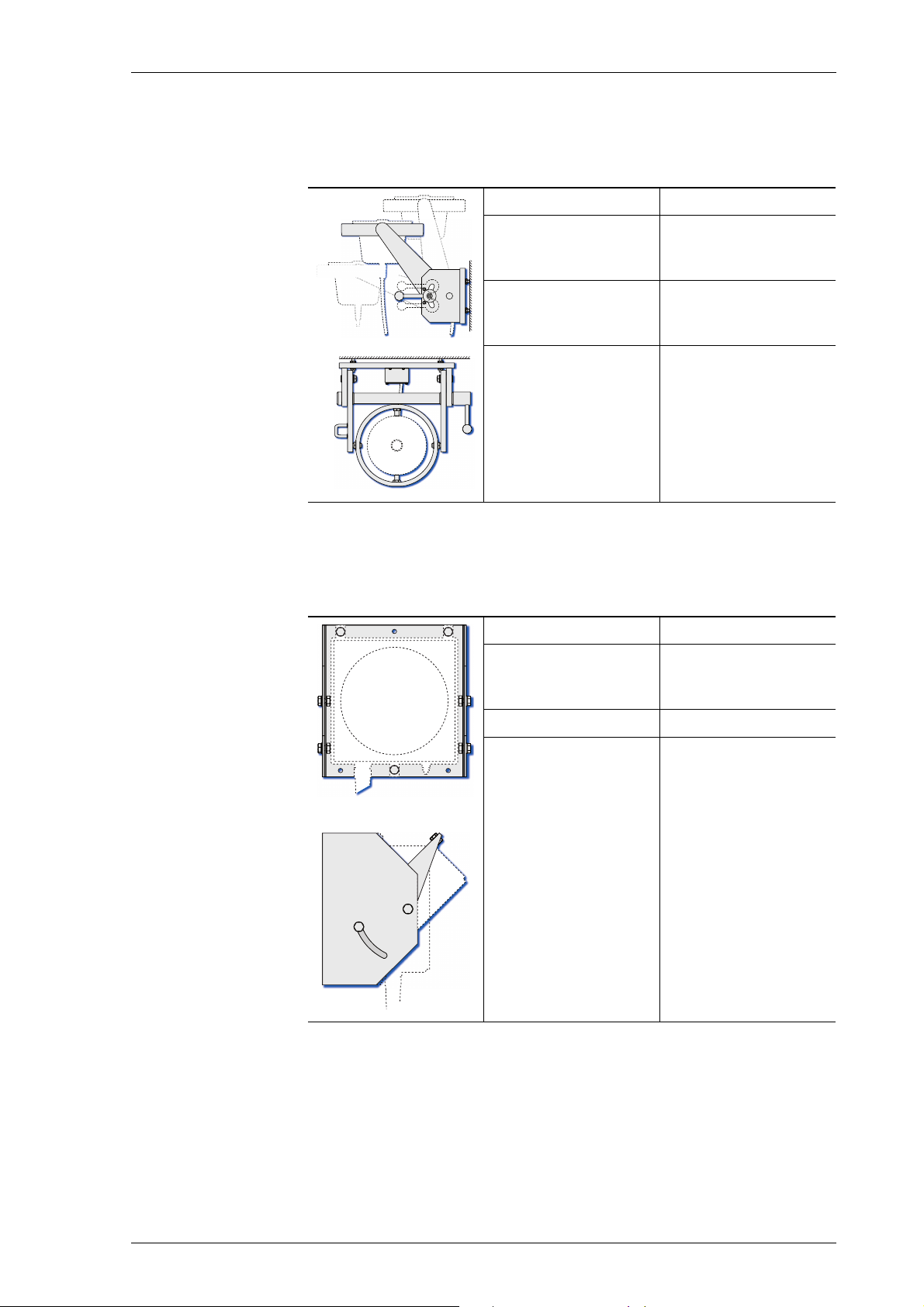
Bearing Repeater Stand and Brackets
The bearing repeater stands, type 4622-AC and -AD, comprise a base,
column and flared top rim in one integral part. It is made of a welded
aluminium alloy and is powder-coated. The repeater gimbal ring is held
in two bearing supports attached to the top rim.
• When the repeater is installed in bearing repeater stand 4622-AC, its
working height is 1.45 m.
• When the repeater is installed in bearing repeater stand 4622-AD, its
working height is 1.30 m.
The connection box, 4894-AD, is attached to the stand’s column.
An optional watertight cover is available to protect the bearing repeater
from the elements.
The bearing repeater bracket type 4890 is made of a welded aluminium
alloy and is powder-coated. It is to be fitted to a bulwark or other vertical
surface. The installation height of the bracket determines the repeaters
working height.
The connection box, 4894-AD, is attached to the side of the bracket.
The adjustable bearing repeater bracket type 4905 is made of aluminium
alloy and is powder-coated. It is to be fitted to a bulwark or other vertical
surface. The height-adjustable bracket arms permit to vary the repeater’s working height in three steps within a range of 250 mm.
The connection box, 4894-AD, is attached to the bracket’s mounting
plate.
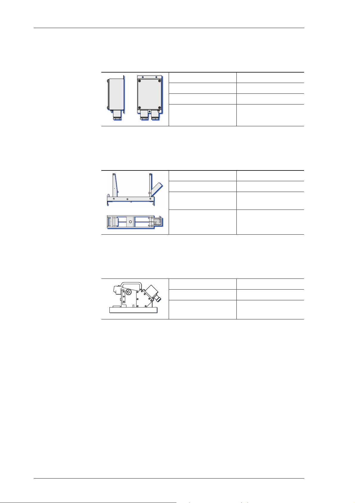
Bulkhead Repeater Bracket
The swivelling bulkhead repeater bracket is made of powder-coated
sheet metal. It permits to install the repeater at an inclined angle relative
to the mounting surface, e.g. when it is mounted high up a bulkhead or
on a ceiling. The angle is adjustable within a range of 45°.
Accessories 1-5

056376/A Analogue Compass Repeaters
Connection Box
The connection box, type 4894-AD, a stainless steel box with cable
glands, is for connecting the bearing repeater and bulkhead repeater to
the gyrocompass system.
umn, or to the side of the bracket/bracket’s mounting plate.
The connection box holds as well the standard USB type B receptacle
for service purposes.
It is either attached to the repeater stand’s col-
Azimuth Device PV 23
The prismatic azimuth device PV 23 (type no. 2535) is a vane-type azimuth device, classified as compass bearing device to be used in combination with the bearing repeater, type 5016-CA.
It is suitable for taking absolute and relative bearings of terrestrial
objects and of celestial bodies (stars and planets).
The near sight vane is equipped with a prism mirror to read absolute
bearings off the compass card and two coloured anti-glare filters.
An index mark at the near side of the PV 23 is used to read relative bearings off the repeater’s verge ring scale.
The far sight vane is equipped with a wire sight and with a pivoting
black azimuth mirror to pick up the reflections of objects at high elevation, i.e. terrestrial bodies.
For more details see “Taking Bearings with the Azimuth Device PV 23”
on page 2-6.
Telescopic Alidade
The telescopic alidade, stock no 60280, not classified as compass bearing device in combination with the bearing repeater, type 5016-CA, for
classified vessels, may also become used with the bearing repeater for
taking bearings on non classified ships only.
It is suitable for taking absolute and relative bearings of magnified terrestrial objects and celestial bodies (stars and planets).
For more details see the separate operation manual of the
telescopic alidade 056339.
1-6 Accessories

Analogue Compass Repeaters 056376/A
1.6 Technical Data
Common Features, all Repeater Types
Environmental Requirements
ambient temperature, operation -25 °C – +55 °C
ambient temperature, storage -25 °C – +70 °C
Power Supply
supply voltage 24 VDC
max. ripple content ±4 Vpp; extreme values may not
exceed 36 V or fall below 18 V
power consumption 6 W max.
Readout Elements
compass cards colour: white on black
illumination: LED backlight, white
card system follow-up speed ≥ 30°/s
max. error of indication ±0.1° at rest, ±0.5° at turn ≤ 20°/s
lubber line illuminated pointer, yellow
Data Input
protocol NMEA 0183 / IEC 61162 at 4800,
9600, 19200, or 38400 Bd., 8N1, or
Plath binary, 9600 Bd., 8N1
evaluated IEC 61162 sentences
gyrocompass heading
magnetic compass heading
heading from THD
nav. status (active source)
central dimming command
Service I/O Port
USB service port Standard USB type B receptacle
$--THS, $--HDT
(talker ID not HC or GP)
$HCHDT, $HCHDM, $HCHDG
$GPTHS, $GPHDT
$PPLAN, $PPNSD (proprietary)
$--DDC or $PPLAI (proprietary)
,
for connection to a Windows host
PC using a vendor-specific USB
communications device class
driver, directly accessible at the
back side of types 5016-CB and CC. For types 5016-CA and -CD the
USB receptacle is accessible inside the connection box housing.
The analogue compass repeater is
accessed via the “SUSI” application, using a proprietary data protocol.
Technical Data 1-7
056376/A Analogue Compass Repeaters
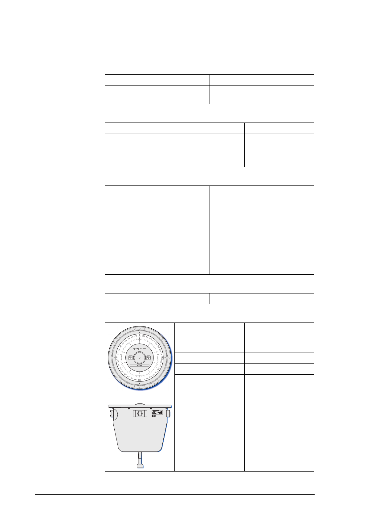
Bearing Repeater, Type 5016-CA
Environmental Requirements
protection grade IP 56 to DIN EN 60529
environmental conditions / EMC
Magnetic Clearance
to standard magnetic compass 0.80 m
to steering magnetic compass 0.50 m
reduced, to standard magnetic compass 0.50 m
reduced, to steering magnetic compass 0.30 m
Readout Elements
360° card diameter
scale graduations
heading scale, numbering
azimuth scale, numbering
10° card diameter
graduation
numbering
verge ring diameter
colour
graduation
numbering
according to IEC 60945, equipment
category “exposed to the weather”
172 mm
outer: every 1°; inner: every 5°
every 10°
every 5°
130 mm
every 0.5°
every 1°
225 mm
white on black
every 1°
every 10°
Controls
Capacitive keys
Dimensions and Weight
diameter at top
(verge ring outer dia.)
height 165 mm
depth 173 mm
weight 5.5 kg
free cable length 2 m
225 mm
1-8 Technical Data
Analogue Compass Repeaters 056376/A
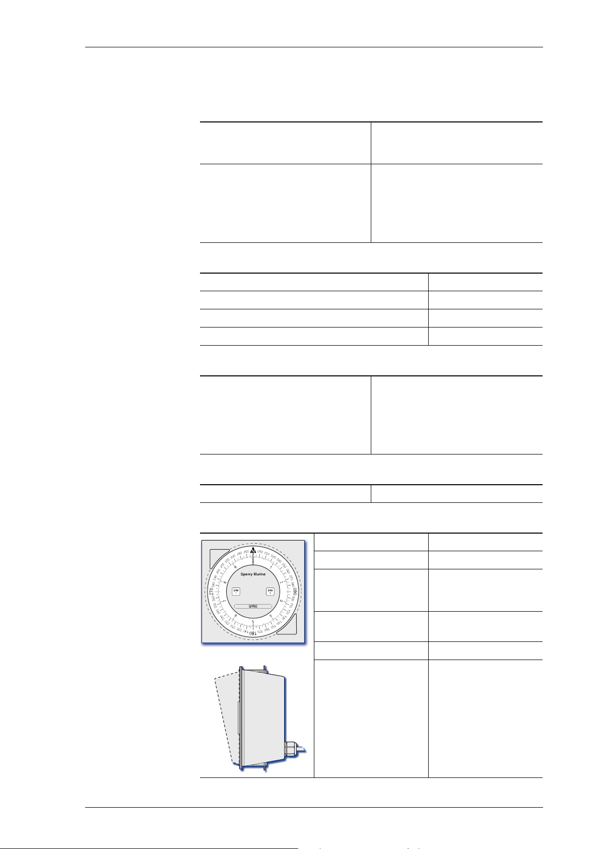
Steering Repeater, Type 5016-CB
Environmental Requirements
protection grade
front side
back
IP 56 to DIN EN 60529
IP 23 to DIN EN 60529
environmental conditions / EMC
installed in console frame
console-mounted, with seal
Magnetic Clearance
to standard magnetic compass 0.75 m
to steering magnetic compass 0.50 m
reduced, to standard magnetic compass 0.45 m
reduced, to steering magnetic compass 0.30 m
Readout Elements
360° card diameter
graduation
numbering
10° card diameter
graduation
numbering
according to IEC 60945,
equipment category “protected
from the weather”
in accordance with IEC 60945,
equipment category “exposed to
the weather”
172 mm
every 5°
every 10°
130 mm
every 0.5°
every 1°
Controls
Push buttons
Dimensions and Weight
width 192 mm
height 192 mm
installation depth
below front plate
projection of sun
shade from front plate
weight 1.25 kg
free cable length 3 m
approx. 125 mm
(including clearance
required for cable)
52 mm
Technical Data 1-9
056376/A Analogue Compass Repeaters
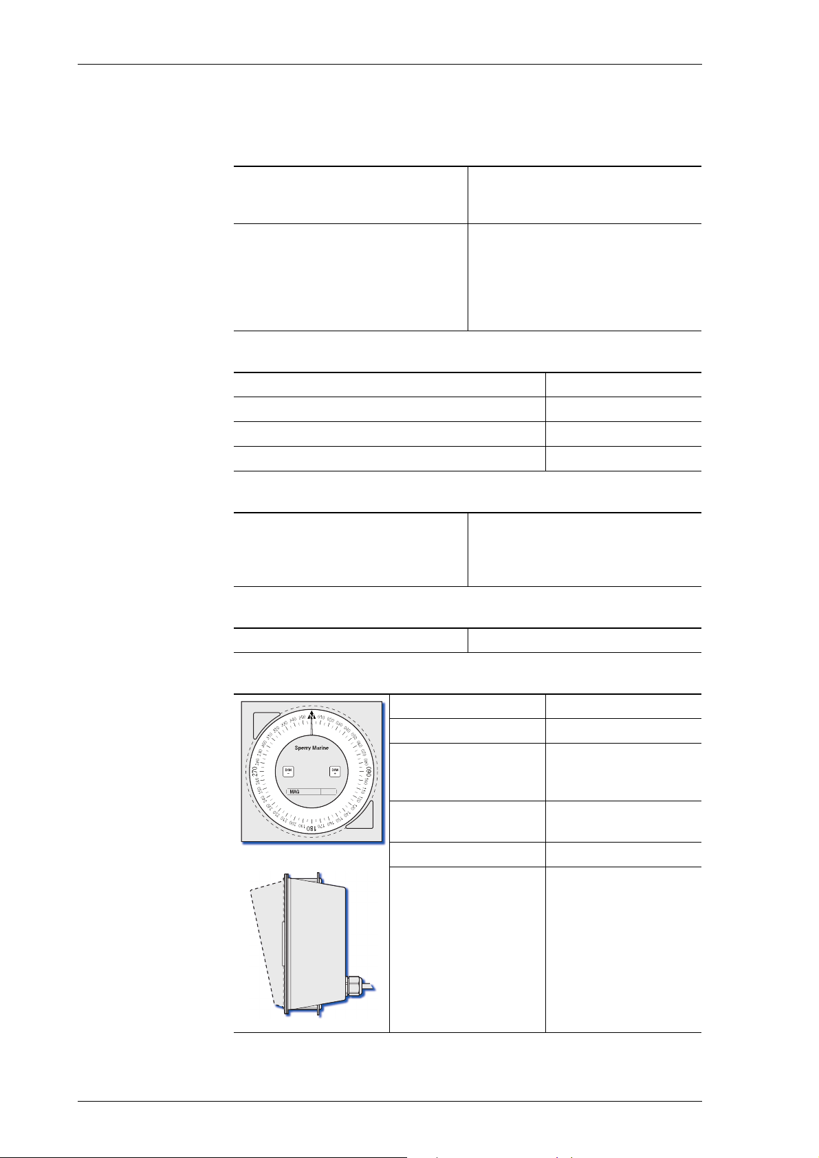
Magnetic Heading Repeater, Type 5016-CC
Environmental Requirements
protection grade
front side
back
IP 56 to DIN EN 60529
IP 23 to DIN EN 60529
environmental conditions / EMC
installed in console frame
console-mounted, with seal
Magnetic Clearance
to standard magnetic compass 0.75 m
to steering magnetic compass 0.50 m
reduced, to standard magnetic compass 0.45 m
reduced, to steering magnetic compass 0.30 m
Readout Elements
360° card
diameter
graduation
numbering
Controls
according to IEC 60945,
equipment category “protected
from the weather”
in accordance with IEC 60945,
equipment category “exposed to
the weather”
172 mm
every 1°
every 10°
Push buttons
Dimensions and Weight
width 192 mm
height 192 mm
installation depth
below front plate
projection of cover
from front plate
weight 1.25 kg
free cable length 3 m
approx. 125 mm
(including clearance
required for cable)
52 mm
1-10 Technical Data

Analogue Compass Repeaters 056376/A
Bulkhead Repeater, Type 5016-CD
Environmental Requirements
protection grade IP 56 to DIN EN 60529
environmental conditions / EMC according to IEC 60945, equip-
ment category “exposed to the
weather”
Magnetic Clearance
to standard magnetic compass 0.70 m
to steering magnetic compass 0.40 m
reduced, to standard magnetic compass 0.45 m
reduced, to steering magnetic compass 0.30 m
Readout Elements
360° card
diameter
graduation
numbering
10° card
diameter
graduation
numbering
172 mm
every 5°
every 10°
130 mm
every 0.5°
every 1°
Controls
Push buttons
Dimensions and Weight
width 200 mm
height 240 mm
depth 83 mm
weight 2.5 kg
free cable
length
3 m
Technical Data 1-11

056376/A Analogue Compass Repeaters
Bearing Stand, Type 4622
Dimensions and Weight
diameter, top rim 444 mm
height, type 4622-AC
type 4622-AD
weight 10 kg
Bearing Repeater Bracket, Type 4890
Dimensions and Weight
width 462 mm
1450 mm
1300 mm
(including connection
box fitted to right or
left hand side)
depth 390 mm
height 185 mm
weight 5.2 kg
1-12 Technical Data
Analogue Compass Repeaters 056376/A
Adjustable Bearing Repeater Bracket, Type 4905
Dimensions and Weight
width 512 mm
depth
lowest position
highest position
height
lowest position
highest position
weight 16.5 kg
560 mm
308 mm
231 mm
481 mm
Bulkhead Repeater Bracket, Stock No. 26857
Dimensions and Weight
width 241 mm
depth 226 mm
(at maximum inclination of repeater)
height 240 mm
weight 3.5 kg
Technical Data 1-13
056376/A Analogue Compass Repeaters
Connection Box, Type 4894-AD
Dimensions and Weight
width 90 mm
depth 60 mm
height 164 mm
weight 0.8 kg
Azimuth Device PV23, Type 2535
Dimensions and Weight
width 62 mm
depth 230 mm
height above repeater top glass
weight 0.6 kg
Telescopic Alidade, Stock no. 60280
Dimensions and Weight
width 236 mm
height 150 mm
weight 3.1 kg
135 mm
1-14 Technical Data

Analogue Compass Repeaters 056376/A
Note
1.7 Declaration of Conformity
Marine Equipment Directive EC Declaration of Conformity:
Northrop Grumman Sperry Marine B.V.
Woltmanstrasse 19
D-20097 Hamburg, Germany
as manufacturer hereby declares that the following specified equipment:
“Analogue Compass Repeaters types 5016-CA, -CB, -CC, -CD”
comply with the Marine Equipment Directive 96/98/EC, as amended.
This equipment has been tested to verify compliance with the
Regulations and Testing Standards as per EC Type Examination (B) and
EC Quality System (D) issued by:
Notified Body No. 0098 Germanischer Lloyd.
The current issue of the detailed Marine Equipment Directive EC
Declaration of Conformity of Northrop Grumman Sperry Marine B.V.
Hamburg is part of the client CD stock no. 56 800.
For further details please contact:
Northrop Grumman Sperry Marine B.V. Hamburg
Regulatory Support Group
Declaration of Conformity 1-15

056376/A Analogue Compass Repeaters
1-16 Declaration of Conformity
Analogue Compass Repeaters 056376/A
2
3
7
8
9
5
4
1
6
Chapter 2: Operation
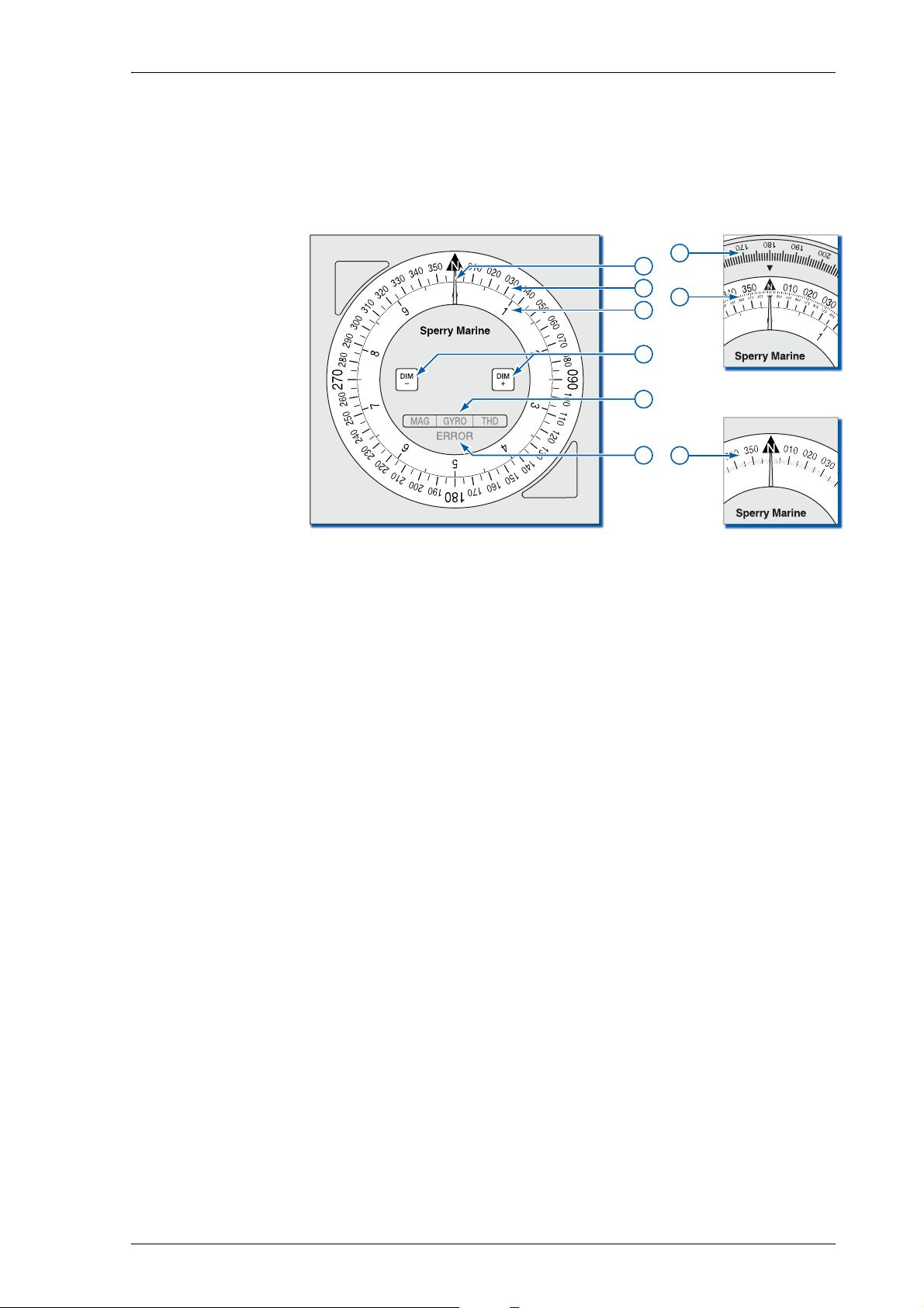
2.1 Readout Elements, Indicators and Controls
Figure 2-1:
Readout elements, indi-
cators and controls
Lubber Line
Indicates the “ahead” direction. Ship’s heading is read off the
compass card(s) at the lubber line.
360° Card
,
Indicates ship’s heading on a 360° (1x) scale. Numbered at 10°,
graduated every 5° (every 1° in magnetic repeater, type 5016-CC).
10° Ca rd
Indicates the “fine” portion of the heading on a 10° (36x) scale.
Numbered every 1°, graduated every 0.5°. Magnetic repeater, type
5016-CC possesses no 10° card.
DIM- / DIM+ keys
Adjust the illumination brightness.
Keep both keys pressed for more than 3 s, then release to initiate
synchronization; keep both keys pressed for more than 10 s, then
release to initiate self test.
Source Indicators
- GYRO = indicating true heading from gyrocompass,
- MAG = indicating magnetic compass heading (raw or corrected),
- THD = indicating true heading from transmitting heading device.
Error indicator
Indicates error conditions visually through blink codes.
Bearing Repeater Verge Ring Scale
Used for taking relative bearings with the azimuth device PV 23.
Bearings read off at the index mark at the “near” side of PV 23.
Bearing Repeater Azimuth Scale
Used for taking absolute bearings with the azimuth device PV 23.
Bearings read off via the mirror prism at the “near” side of PV 23.
Readout Elements, Indicators and Controls 2-1

056376/A Analogue Compass Repeaters
Note
Note
2.2 Powering up the Repeaters
The analogue compass repeaters are not equipped with power
switches. The devices power up as soon as supply power is applied.
2.3 Data Protocol and Source Detection
When it is first connected to the gyrocompass system, the repeater
auto-detects the communication parameters by checking for a valid protocol/baudrate combination in the following order:
• NMEA 0183 at 4800 Bd.
• NMEA 0183 at 38400 Bd.
• NMEA 0183 at 9600 Bd.
• NMEA 0183 at 19200 Bd.
• Plath binary format (9600 Bd.)
Once the repeater has recognized valid data, it stores the communication parameters and will re-activate them at subsequent power-ups to
become quickly operative. Should no data be recognized using the
stored communication parameters, the repeater executes the autodetection routine again.
The communication protocol and baudrate may be hard-set in the
repeater configuration. This will disable auto-detection.
Within a standard Sperry Marine NAVIGAT gyrocompass system, the
analogue repeater will receive the heading source selection status from
the compass system.
If the NMEA 0183 protocol is used, the repeater evaluates the proprietary $PPLAN or $PPNSD sentences. If the PLATH protocol is used, the
heading data itself contains a source indicator.
In systems where the NMEA 0183 protocol is used but no $PPLAN or
$PPNSD sentences are received, the repeater determines the active
source by searching the incoming data for valid heading sentences in
the following order of priority:
• $HETHS (source = GYRO)
• any $--THS, except $GPTHS (source = GYRO)
• $HEHDT (source = GYRO)
• any $--HDT, except $GPHDT or $HCHDT (source = GYRO)
• $GPTHS (source = THD)
• $GPHDT (source = THD)
• $HCHDT (source = MAG)
• $HCHDM (source = MAG)
• $HCHDG (source = MAG)
The range of recognized sentences for each source may be restricted by
hard-setting the accepted sentences in the repeater configuration.
Should the currently active heading source get lost, a timeout condition
will occur, the compass card may freeze and the repeater will search the
incoming data for other valid heading sentences in order of priority.
2-2 Powering up the Repeaters
 Loading...