

Page 1
OPERATING INSTRUCTIONS
DIGITAL CLAMP METER
Model DSA600TRMS
IMPORTANT: RECEIVING INSTRUCTIONS
Visually inspect all components for shipping damage. If you find damage,
notify the carrier at once.
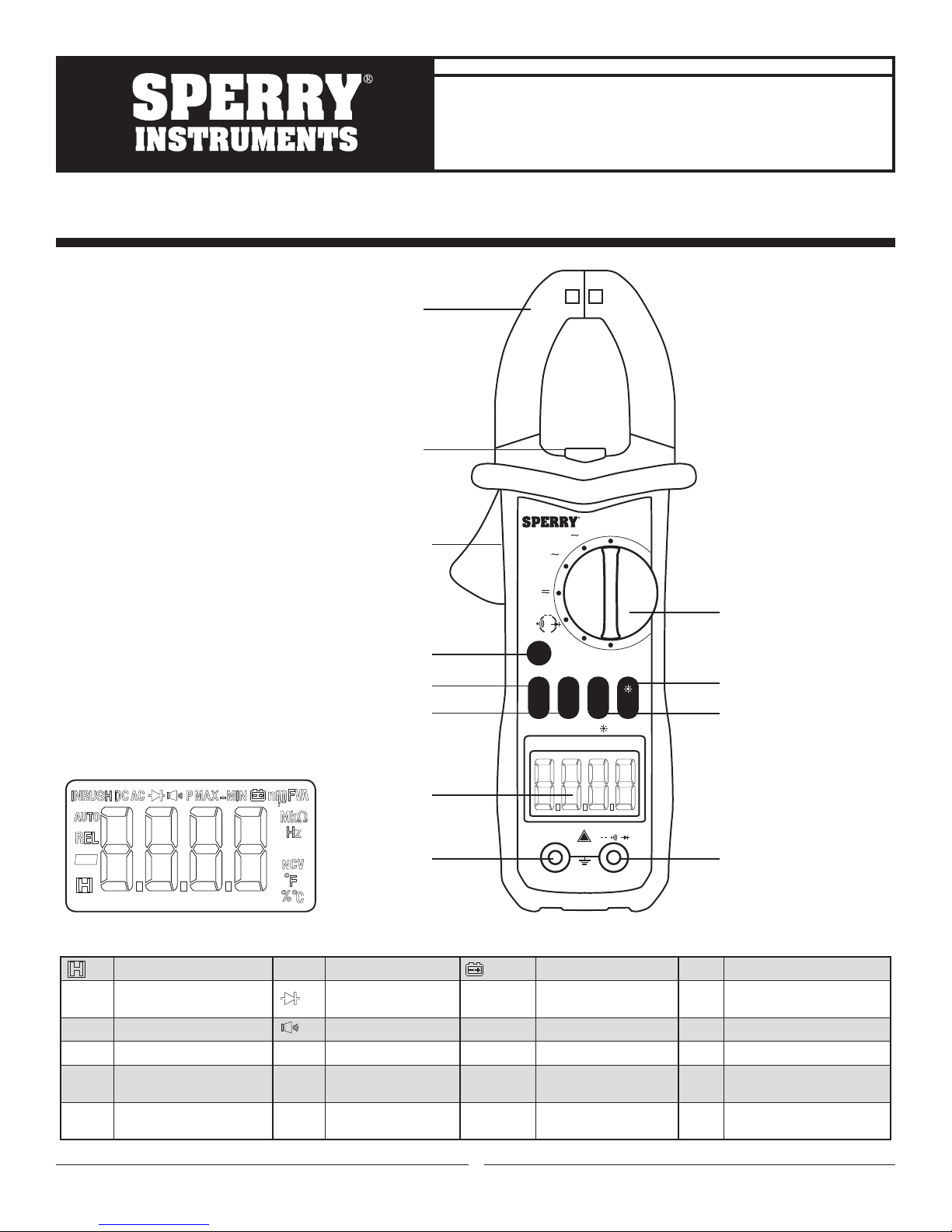
Clamp Jaw
Light
Trigger
Function Selection (SEL)
Frequency / Duty Cycle (Hz/%)
Inrush Current /
Relative Measurement (INR/REL)
Shipping damage is NOT covered by warranty. The carrier is responsible
for all repair or replacement costs resulting from damage in shipment.
NCV
600A
60A
Hz%
V
}
SEL
}
Ω
°C°F
OFF
Dial
HOLD / Backlight /
Clamp Light
PEAK
INR
HZ%
REL
- AUTO-POWER OFF Press 2 Sec
DSA600TRMS
HOLD
HOLD
Peak Button (PEAK HOLD)
Figure 2
Data Hold AC Alternating Current Low Battery NCV Non-contact Voltage Detection
-
REL
AUTO
INRUSH
DC
Negative Value Diode Check nF, µF, mF
Relative Measurement Audible Continuity Check mV, V Millivolt, Volt °C Degrees Celsius
Auto Ranging P MAX Peak maximum value A Ampere (Current) % Duty Cycle
Inrush Current Measurement P MIN Peak minimum value Ω, kΩ, MΩ
Direct Current
P MAXMIN
LCD Screen
!
CATIII
600V
Figure 1
V/Ω/Hz
}
}
V/Ω/Hz
°F Degrees Fahrenheit
OL Overload
EF Electric Field Detection
COM
COM Terminal Input Terminal
Nanofarad, Microfarad,
Millifarad (Capacitance)
Ohm, Kiloohm, Megaohm
(Resistance)
Peak to Peak value Hz, kHz, MHz
Hertz, Kilohertz,
Megahertz (Frequency)
1
Page 2
1. FEATURES AND MEASUREMENT FUNCTIONS
• 5999 count display
• Contoured body provides comfortable single handed grip
• Auto ranging
• Clamp illuminating LED and backlit LCD to facilitate working in dimly lit situations
• Auto shut off feature to extend battery life
• Auto shut off disable feature
• Low battery indicator
• Data hold
• Polarity indication: Automatic, + Implied, Negative Polarity Indicator
• Over-range indication: ‘0L’ or ‘-0L’
• Overload protection
• Non-contact voltage detection: 50 to 500 VAC
• Temperature measurement: -20°C to 1000°C (-4°F to 1832°F) The K type thermocouple
provide (TP-01A) is rated 400°C max.
• Resistance measurement: 0.1Ω - 60MΩ
• Continuity check: Provides an audible indication above 50Ω
• Diode check: Measure the forward voltage drop across a diode junction
• Capacitance measurement: 1nF to 1mF
• DC voltage measurement: 600 VDC max.
• AC voltage measurement: 600 VAC max.
• AC current measurement: 600A max.
• Frequency measurement: up to 9.999MHz
• Duty cycle measurement
• Inrush current measurement: First 100ms from being triggered
• Relative measurement: Used for comparative measurement
• Peak Hold measurement: Captures the + Peak value, - Peak value and Peak to Peak value
2. SAFETY WARNINGS
• This instruction manual contains warnings and safety rules which must be observed by
the user to ensure safe operation of the instrument and retain it in safe condition.
• Read through and understand the instructions contained in this manual before using the instrument.
• Keep the manual at hand to enable quick reference whenever necessary.
• The instrument is to be used only in its intended applications.
• Understand and follow all the safety instructions contained in the manual.
• It is essential that all safety instructions are adhered to.
• Failure to follow the safety instructions may cause injury, instrument damage
The symbol indicated on the instrument means that the user must refer to the related parts in the
manual for safe operation of the instrument. It is essential to read the instructions wherever the symbol
appears in the manual.
DANGER is reserved for conditions and actions that are likely to cause serious or fatal injury.
WARNING is reserved for conditions and actions that can cause serious or fatal injury.
CAUTION is reserved for conditions and actions that can cause injury or instrument damage.
DANGER
• Never make measurement on a circuit in which voltage over 600V exists.
• Do not exceed the CAT rating of the measuring device
• Do not attempt to make measurement in the presence of flammable gases.
The use of the instrument may cause sparking, which can lead to an explosion.
• Transformer jaw tips are designed to not short the circuit during a test. If equipment under test has exposed
conductive parts extra precaution should be taken to minimize the possibility of shorting.
• Never use the instrument if its surface or your hand is wet.
• Do not exceed the maximum allowable input of any measuring range.
• Never open the battery cover during a measurement.
• The instrument is to be used only in its intended applications or conditions.
Use in other than as intended may cause instrument damage or serious personal injury.
2
Page 3
WARNING
• Never attempt to make any measurement if any abnormal conditions are noted, such as broken case,
cracked test leads and exposed metal part.
• Do not turn the function selector switch with plugged in test leads connected to the circuit under test.
• Do not install substitute parts or make any modification to the instrument.
Return the instrument to your distributor for repair or recalibration.
• Do not try to replace the batteries if the surface of the instrument is wet.
• Always switch off the instrument before opening the battery compartment cover for battery replacement.
CAUTION
• Set the Function Switch to an appropriate position before starting measurement.
• Firmly insert the test leads.
• Disconnect the test leads from the instrument for current measurement.
• Do not expose the instrument to the direct sun, high temperature and humidity or dewfall.
• Be sure to power off the instrument after use. When the instrument will not be in use for a long period,
place it in storage after removing the batteries.
• Use only a soft cloth dampened with water or neutral detergent for cleaning the meter.
Do not use abrasives, solvents or harsh chemicals. Allow to dry thoroughly before use.
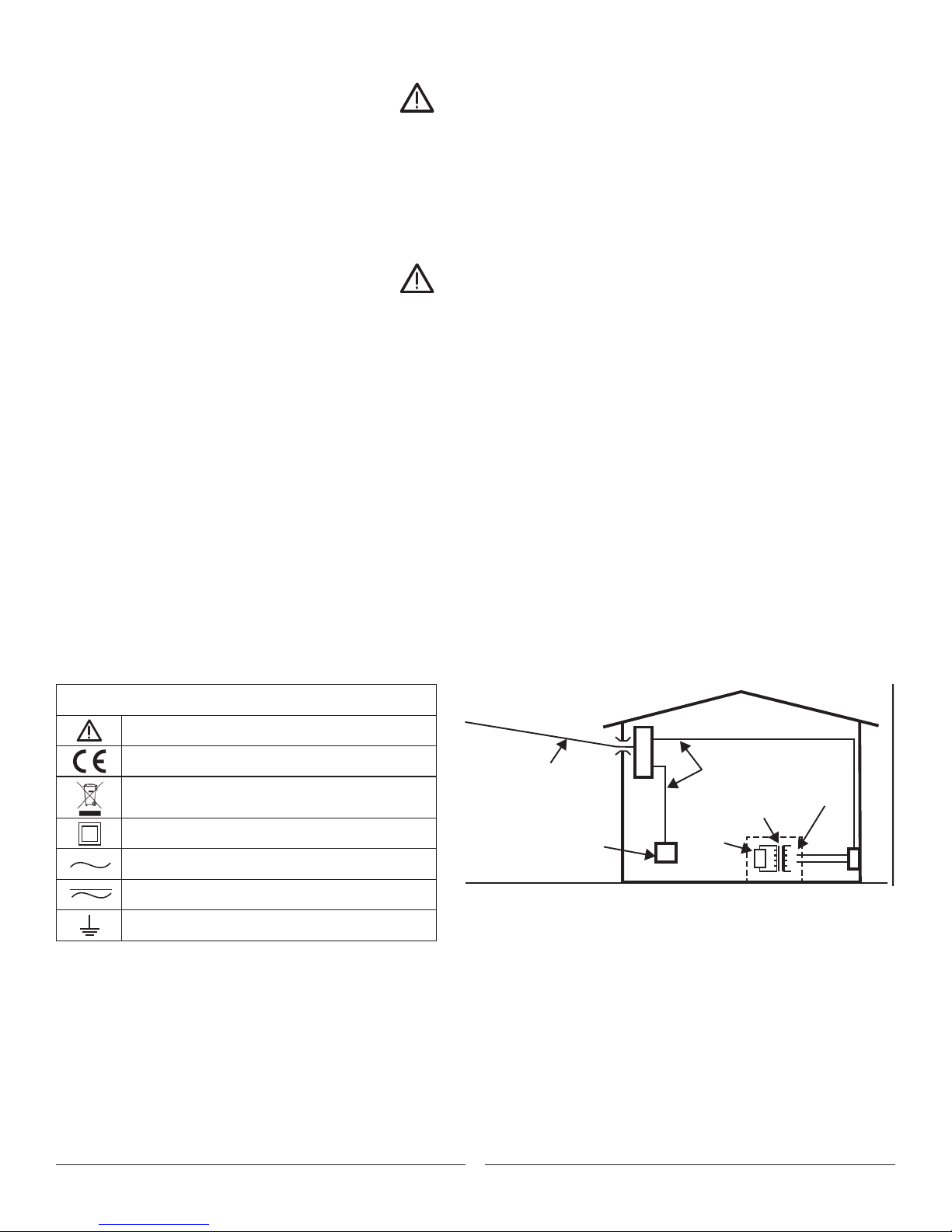
Measurement categories (Over-voltage categories)
To ensure safe operation of measuring instruments, IEC61010 establishes safety standards for various electrical
environments, specified as CAT I through CAT IV, and called measurement categories. Higher-numbered categories
correspond to electrical environments with greater momentary energy, so a measuring instrument designed for CAT III
environments can endure greater momentary energy than one designed for CAT II.
• CAT I: Secondary electrical circuits connected to an AC electrical outlet through a transformer or similar device.
• CAT II: Primary electrical circuits of equipment connected to an AC electrical outlet by a power cord.
• CAT III: Primary electrical circuits of the equipment connected directly to the distribution panel, and feeders
from the distribution panel to outlets.
• CAT IV: The circuit from the service drop to the service entrance, and to the power meter and primary over
current protection device (distribution panel).
Symbols
Incoming wire
Important Information; Refer to manual
Conformité Européene (“European Conformity”)
Designates the product as recyclable
electronic waste per WEEE Directive
Double Insulated
AC (Alternating Current)
AC/DC Selectable (Alternating Current/Direct Current)
Earth Ground
CAT. IV
Socket
Interior wiring
CAT. III
Transformer
CAT. I
CAT. II
3
Page 4
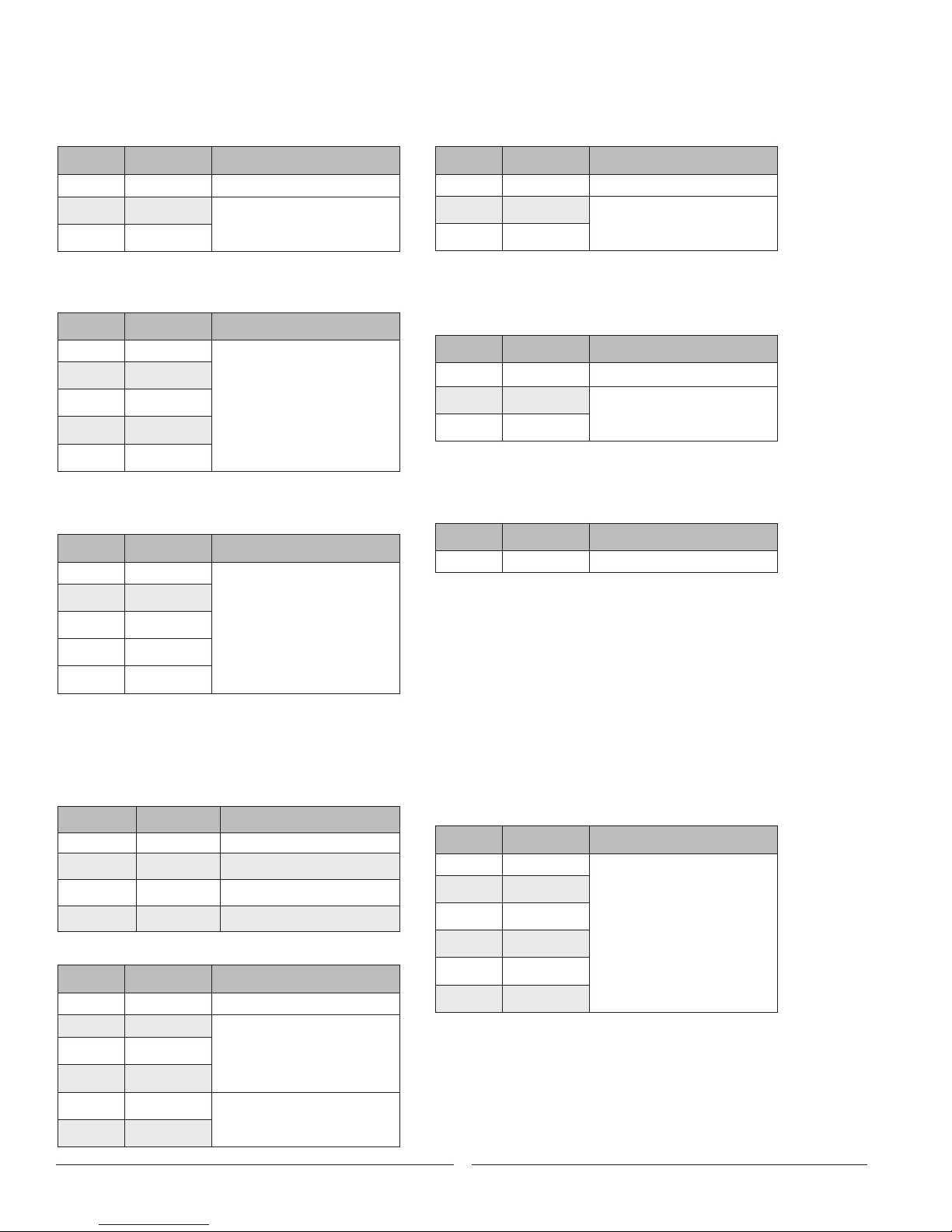
3 . SPECIFICATION
3-1. Measuring range & accuracy
(Accuracy guaranteed at 23ºC ± 5ºC, humidity <75%)
AC CURRENT
RANGE RESOLUTION ACCURACY
6A 0.001A
60A 0.01A
600A 1A
- maximum/input current: 1000A AC
- Frequency range: 50Hz
± (3.5% + 20)
± (2.5% + 8)
DC VOLTAGE
RANGE RESOLUTION ACCURACY
60mV 0.01mV
600mV 0.1mV
6V 0.001V
60V 0.01V
600V 0.1V
- Input impedance: 10MΩ
- Maximum input voltage: 600V DC
± (0.5% + 5)
FREQUENCY
RANGE RESOLUTION ACCURACY
99.99Hz 0.01Hz
999.9Hz 0.1Hz
9.999kHz 10Hz
9999HZ 1Hz
99.99kHz 100Hz
- Range: 10Hz ~ 100kHz
- Input voltage range: ≥ 2mV AC (RMS)
(Higher frequencies require a larger input voltage)
- Input impedance: 10MΩ
- Maximum/ input voltage: 250V AC (RMS)
± (.5% + 3)
TEMPERATURE MEASUREMENT
RANGE RESOLUTION ACCURACY
0˚C - 300˚C 1 ±(1.0%+3)
301˚C - 1000˚C 1 ±(1.9%+5)
32˚C - 600˚F 1 ±(1.2%+6)
601˚F - 1832˚F 1 ±(1.9%+6)
RESISTANCE
RANGE RESOLUTION ACCURACY
600Ω 0.1Ω
6kΩ 0.001kΩ
60kΩ 0.01kΩ
± (0.8% + 10)
± (0.8% + 3)
SURGE CURRENT
RANGE RESOLUTION ACCURACY
6A 0.001A
60A 0.01A
600A 1A
- Inrush measurement time: 100ms
- Amperage range: 20 ~ 600A
- Frequency range: 40 ~ 400Hz
<20A reference only
± (5% + 60)
AC VOLTAGE
RANGE RESOLUTION ACCURACY
6V 0.001V
60V 0.01V
600V 0.1V
- Input impedance: 10MΩ
- Maximum input voltage: 600V AC (RMS)
- Frequency range: 40 ~ 1000Hz
± (1.2% + 5)
± (0.8% + 5)
DUTY CYCLE
RANGE RESOLUTION ACCURACY
0.1–99.9% 0.1% ± 3% + 5
Duty ratio (Clamp Jaws):
- Frequency response: 10 ~ 1kHz ; - Input current range:
≥20A AC (RMS)
- Maximum input current: AC 600A
Duty ratio (Test Leads):
- Frequency response: 10 ~ 10kHz; - Input voltage range:
≥ 60mV AC
- Input impedance: 10MΩ; - Maximum input voltage:
600V AC (RMS)
Duty ratio HZ / % :
- Frequency response: 10 ~ 10MHz; - Input voltage range:
≥ 2V AC (RMS) (Higher frequencies require a
larger input voltage)
- Maximum /input voltage: 250V AC (RMS)
CAPACITANCE
RANGE RESOLUTION ACCURACY
6nF 1pF
60nF 10pF
600nF 100pF
6μF 1nF
60μF 10nF
600μF 100nF
± (3% + 5)
600KΩ 0.1kΩ
6MΩ 0.001MΩ
± (1.2% + 3)
60MΩ 0.01MΩ
4
Page 5

3-2. General Specification
• The maximum voltage allowed between terminal and ground: 1000 VDC or 750 VAC
• Altitude: Maximum 2000m
• Display: 5999 count Backlit LCD
• Sampling time: ~ 3 times / sec
• Automatic power off: 15 Minutes (Unless disabled)
• Power: DC 4.5V
• Battery type: (3) 1.5V AAA
• Temperature coefficient: <.1 x (specified accuracy) / °C
• Operating temperature: 18˚C ~ 28˚C
• Storage temperature: -10˚C ~ 50˚C
• Size: 2.75” x 8.25” x 1.55”
• Weight: ~266 grams (Including batteries, excluding leads)
3-3. Accessories
• 1 red & 1 black 1000V, 20A test lead
• 1 K-type thermocouple (Temperature probe)
• 3 AAA batteries
• Carrying case
4. PREPARATION FOR MEASUREMENT
4-1. Check the condition of the meter
Do not use a meter with visible signs of damage. Examine the meter housing before you use the product. Look for
cracks, missing plastic or exposed metal. Carefully examine the insulation around the Common and Input terminals.
4-2. Check the battery voltage
Start with the dial in the “OFF” position then rotate the dial to any position. Confirm that the low battery symbol
is not displayed on the LCD screen. If the low battery symbol is displayed follow the instructions in Section 7,
Battery Replacement. (It is important to start from the "Off" position to ensure that a blank screen is not due to the
auto off feature.)
4-3. Check the battery cover
The battery cover must be in place and securely fastened before powering on the meter or connecting test leads
to a circuit. See Section 7, Battery Replacement
4-4. Check test lead condition, continuity and rating
Do not use damaged test leads. Examine the test leads for worn or cracked insulation. Check test lead continuity.
Do not use test leads in applications that exceed their CAT rating. Check the CAT rating of the test lead and
refer to Figure 3.
4-5. Checking the switch setting & operation
Confirm the dial is set to the correct position for the measurement function being performed. Confirm that the
symbols displayed on the LED screen match the measurement function. (Refer to Figure 2). Ensure that the
Data Hold feature is disabled.
5. MEASUREMENT
5-1. Temperature
1. Remove the test leads
2. Connect the supplied K-type thermocouple (Temperature probe) to the common and input terminals.
Ensure that the red positive (+) side is connected to the input terminal.
3. Rotate the dial to the °C °F position
4. Contact the sensor (metal part) of K-type temperature probe to the object under test.
5. The temperature of the object will be displayed on the LCD screen
6. Press the SEL button to toggle between Celsius and Fahrenheit
5
Page 6

5-2. Resistance / Continuity / Diode / Capacitance
Resistance
1. Install the test leads
2. Rotate the dial to the position
3. Confirm “OL” is displayed on the LCD screen
4. Short the tips of the test leads together and
confirm the LCD screen shows near zero
5. Connect the test leads across the device
to be tested
6. The resistance of the device will be displayed
on the LCD screen
Continuity
1. Install the test leads
2. Rotate the dial to the position
3. Press the SEL button to toggle through the functions
until is displayed on the LCD screen
4. Confirm “OL” is displayed on the LCD screen
5. Short the tips of the test leads together and the LCD screen
should show near zero and the meter should emit a tone
6. Connect the test leads across the device to be tested
7. A tone will be emitted if the resistance is < 50Ω
Diode test
1. Install the test leads
2. Rotate the dial to the position
3. Press the SEL button to toggle through the functions
until is displayed on the LCD screen
4. Confirm “OL” is displayed on the LCD screen
5. Connect the test leads probes to the anode and
cathode of the diode
6. Record the measurement displayed
7. Reverse the connections and record the
measurement displayed
(The LCD screen should show ”OL” in one direction and a small
forward voltage drop in the other. The forward voltage drop
varies. Typical values are .7V for silicon diodes and .3V for
geranium diodes. Please refer to the diode datasheet for specific
values. If there is a voltage drop in both directions the diode is
shorted. If “OL” is displayed in both directions the diode is open)
Capacitance
1. Remove the capacitor from the circuit
2. Ensure that the capacitor is properly discharged
3. Install the test leads
4. Rotate the dial to the position
5. Press the SEL button to toggle through the functions
until "nF" is displayed on the LCD screen
6. Connect the test leads to the capacitor terminals. (It will take
a few seconds for the capacitance to be displayed)
5-3. DC Voltage
1. Install the test leads
2. Rotate the dial to the position
3. Confirm DC V is displayed on the LCD screen
4. If DC V is not displayed press the SEL key to toggle between ACV and DCV
5. Connect the test leads to the circuit
6. The DC voltage will be displayed on the LCD screen
5-4. AC Voltage
1. Install the test leads
2. Rotate the dial to the position
3. Confirm AC V is displayed on the LCD screen
4. If AC V is not displayed press the SEL key to toggle between DCV and ACV
5. Connect the test leads to the circuit
6. The AC voltage will be displayed on the LCD screen
5-5. AC Current
1. Remove the test leads
2. Rotate the dial to the 60Ã or 600Ã position
3. Press the trigger to open the clamp jaws and place the jaws around a single conductor.
4. The current flowing through the conductor will be displayed on the LCD screen
5-6. Frequency
1. Set up the meter for an AC voltage or current measurement and press the Hz% button
2. "Hz" should be displayed on the LCD screen
3. Connect the test leads probes to the circuit
2. The meter will display the measured frequency on the LCD screen
5-7. Duty cycle
1. Set up the meter for an AC voltage or current measurement and press the Hz% button
2. "Hz" should be displayed on the LCD screen
3. Press the Hz% button a second time and "%" should be displayed
4. The meter will display the measured duty cycle on the LCD screen
5-8. Inrush
1. Remove the test leads
2. Rotate the dial to the 60Ã or 600Ã position
3. Press the INR/REL button for 2 seconds or more
4. Confirm "INRUSH" is displayed on the LCD screen
5. Turn off the device of which you will be checking the inrush current
6
Page 7
6. Press the trigger to open the clamp jaws and place the jaws around a single conductor.
k
(Easily accomplished with the use of a line splitter)
7. Turn on the device being tested
8. The inrush current during the 100ms after start-up will be displayed on the LCD screen
9. Press the INR/REL button again to clear the display
10. Press and hold the INR/REL button to exit the function
5.9. Relative measurement
1. While taking a measurement press the INR/REL key
2. This puts the meter in the relative value measurement mode.
3. Pressing the INR/REL key makes the currently displayed value a reference value in memory.
4. Subsequent measurements will be displayed as the measured value minus the stored value.
5. The meter does not auto range during this function
6. The meter will display “OL” if the measurement exceeds the range
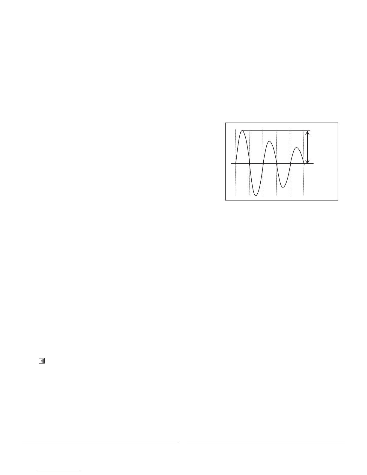
5-10. Peak Hold
1. The Peak Hold function can be used in either the voltage or current settings
2. The meter will capture and hold the highest and lowest values measured
3. The meter does not auto range during this function
4. Follow the first few steps for the measurement type being performed
5. Press the Peak/Hold button after the meter is set to take the measurement
6. "PMAX" will be displayed on the LCD screen
7. Begin taking the measurement
7. The highest value measured will be displayed on the LCD screen
8. If "OL" is displayed the range will need to be changed manually
9. To change the range press and hold the Hz% button for two or more seconds
followed by pressing the Peak/Hold button
10. "PMAX" will be displayed on the LCD screen
11. Retake the measurement
12. If "OL" is still displayed repeat step 9
13. Once the range is set properly the Peak/Hold button can be used to toggle
through PMAX, P MIN and PMAX-MIN
I pea
T
6. OTHER FEATURES
6.1. Clamp jaw light / Backlit LCD screen
1. Rotate the dial to any position other than off
2. Press and hold the HOLD button for 2 seconds or more
3. The backlit LCD screen will illuminate
4. If the meter is on either of the current settings the clamp jaw light will also illuminate
5. The backlit LCD screen and clamp jaw light will remain lit for 15 seconds,
or press the HOLD button for 2 seconds to turn them off
6.2. Auto shut off / Auto shut of disable
1. The meter has an auto shut off feature to preserve battery life
2. The meter will shut off after 15 minutes of non-use
3. Data hold information will not be retained if the auto off feature is enacted
4. If the meter is turned off by this feature the operator should rotate the dial back to the
"OFF" position to resume normal operation
5. The auto shut off feature can be disable by holding down the "SEL" key when rotating the dial from the off position
6.3. Low battery indicator
1. The meter has a low battery indicator that will alert the user when the voltage is too low to provide accurate readings
2. Replace the batteries when this indicator is displayed (See Section 7, Battery Replacement)
6.4. Data hold
1. The meter has a data hold feature that will retain the measured value on the LCD screen.
2. Press the HOLD button momentarily to retain the measured value
3. The symbol will be displayed while the value is being retained
4. Press the HOLD button again to resume normal operation
6.5. Polarity indication
1. The meter displays "-" for negative values, positive is implied
6.6. Overload indication
1. When the input exceeds the measuring range "OL" or "-OL" is displayed on the LCD screen
7
Page 8
DSA600TRMS
OFF
°C°F
COM
CATIII
600V
- AUTO-POWER OFF Press 2 Sec
PEAK
HOLD
INR
REL
HZ%
SEL
HOLD
!
Ω
V/Ω/Hz
V/Ω/Hz
}
}
}
}
60A
V
Hz%
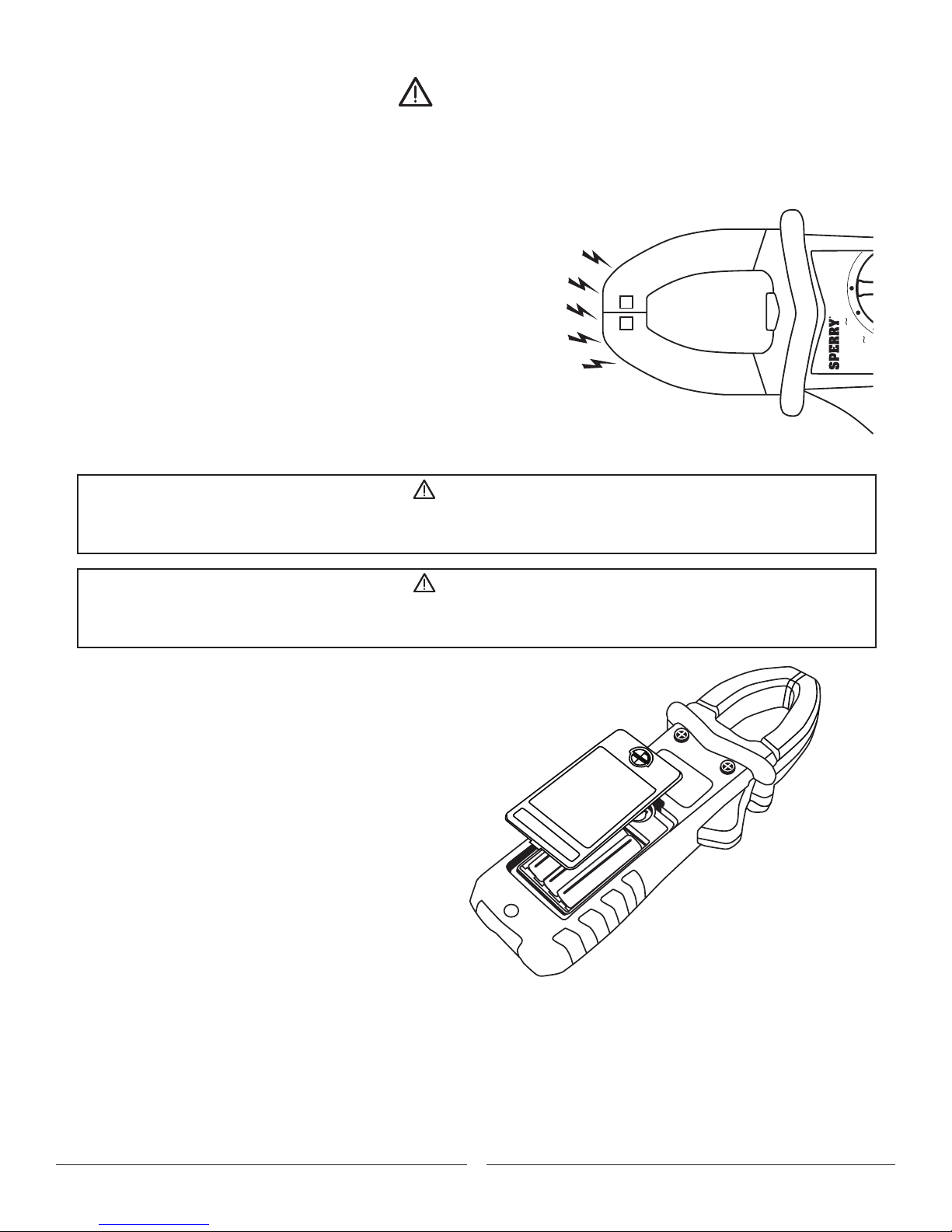
6-7. Non-contact Voltage Detection
WARNING
• Test on a known live source before use
• Even if the meter does not provide indication, potentially hazardous voltage could still be present
(The meter will only detect voltages above 50VAC and only when conditions are correct)
• The meter can be affected by: Distance from voltage source, Condition of meter and batteries, Shielded wires,
Metal enclosures, Insulation thickness, Static charge among other things
1. Remove the test leads
2. Rotate the dial to the “NCV” position
3. Confirm “EF” and “NCV” is indicated on the LCD screen
4. Position the tip of the clamp jaws near the voltage source
5. A continually cycling tone will be emitted and the clamp light will
flash when the meter senses AC voltage greater than ~50V
(The meter is sensitive to electrostatic fields. Occasionally a
static charge may interfere with the meter detection and the
meter may omit a tone momentarily.)
7. BATTERY REPLACEMENT
WARNING
• To avoid electrical hazard, set the Function Switch to “OFF” and remove the test leads from the
instrument before trying to replace batteries.
NCV
600A
CAUTION
• Do not mix old and new batteries.
• Install batteries in correct polarity as indicated in the Battery Compartment.
1. Rotate the dial to the "OFF" position and
remove the test leads
2. Rotate the 1/4 turn fastener CCW with a
screwdriver or coin and remove the cover
3. Replace the batteries observing correct polarity
4. Use new R03 (AAA) or LR03 / 1.5V batteries.
5. Reinstall the door and rotate the 1/4 turn
fastener CW to secure the cover.
Replace the batteries when a low battery symbol
is displayed on the LCD screen.
When the battery is completely exhausted, the display
will appear blank and no symbol will be shown.
8. MAINTENANCE
Cleaning: Use only a soft cloth dampened with water or neutral detergent for cleaning the meter.
Do not use abrasives, solvents or harsh chemicals. Allow to dry thoroughly before use.
8
Page 9

SPERRY INSTRUMENTS LIMITED LIFETIME WARRANTY
Subject to the exclusions and limitations detailed below, Sperry Instruments provides a limited lifetime warranty on products
of its manufacture will be free from defects in materials and workmanship under normal use and service.
Limited
Limited means that Sperry Instruments warrants to the original purchasers of products from Sperry Instruments authorized
distributors at the time of shipment such products shall be free of defects in material and workmanship while the tool is used
under normal working conditions. Standard wear and tear, dulling over time, overloading, misuse, and acts of God are not
covered under warranty. This warranty does not cover batteries, fuses, or test leads.
When a warranty claim arises, the purchaser must contact Sperry Instruments. If the defect comes under the terms of this
limited warranty, Sperry Instruments will arrange, at its sole discretion, one of the following options:
• Product will be replaced
The purchaser is solely responsible for determining the suitability of Sperry products for the purchaser’s use or resale, or
for incorporating them into articles or using them in the purchaser’s applications. The distributor is authorized to extend the
foregoing limited warranty to its original purchasers in connection with the sales of Sperry products, provided that such products
shall not have been altered by the distributor. The distributor shall be fully responsible for any warranties the distributor makes to
its purchasers which are broader or more extensive than Sperry’s limited warranty.
Lifetime Warranty
Warranty Limitation: The forgoing warranties are exclusive and are in lieu of all other express and implied warranties whatsoever,
including but not limited to implied warranties of merchantability and fitness for a particular purpose. The foregoing warranties
do not cover ordinary wear and tear, abuse, misuse, overloading, alterations, products which have not been installed, operated
or maintained in accordance with Sperry’s written instructions. Test leads, fuses, batteries and calibration are not covered under
any implied warranty. “Lifetime” of products that are no longer offered by Sperry will be either repaired or replaced with an item
of Sperry Instruments choice of similar value. Lifetime is defined as 5 years after Sperry discontinued manufacturing the product,
but the warranty period shall be at least ten years from date of purchase. Original proof of purchase is required to establish
original ownership of product.
No warranty will be honored unless an invoice or other proof of purchase date is provided to Sperry Instruments. Hand written
receipts or invoices will not be honored.
©2016 Product Power, LLC All rights reserved.
- See more at: http://www.sperryinstruments.com/en/resources/warranty-page#sthash.4sNKZu3b.dpuf
Sperry Instruments
800-645-5398
Menomonee Falls, WI 53051
sperryinstruments.com
DSA600TRMS 0416
9
 Loading...