

Page 1
WARRANTY
ONE YEAR LIMITED WARRANTY
SPERRY INSTRUMENTS, INC. warrants that this AWS
instrument has been carefully tested, inspected, and
warranted for one (1) year from the date of purchase by
the original end user purchaser, and the instrument has
not been misused, damaged due to negligence, neglect
or unauthorized repair, abused or used contrary to the
operating instructions. Instruments and proof of
purchase in the form of a legible copy or original of the
sales receipt clearly identifying the distributor, model
number and date of purchase must be returned to
SPERRY INSTRUMENTS, INC. Attention: Customer
Service Center, 2150 Joshua’s Path, Suite 302,
Hauppauge, NY 11788, Postage prepaid for
examination of verification of manufacturing defect
under warranty. SPERRY INSTRUMENTS, INC. shall
be the sole judge of such defect. Liability of SPERRY
INSTRUMENTS, INC. shall be limited to the repair or
11/02 Form #312
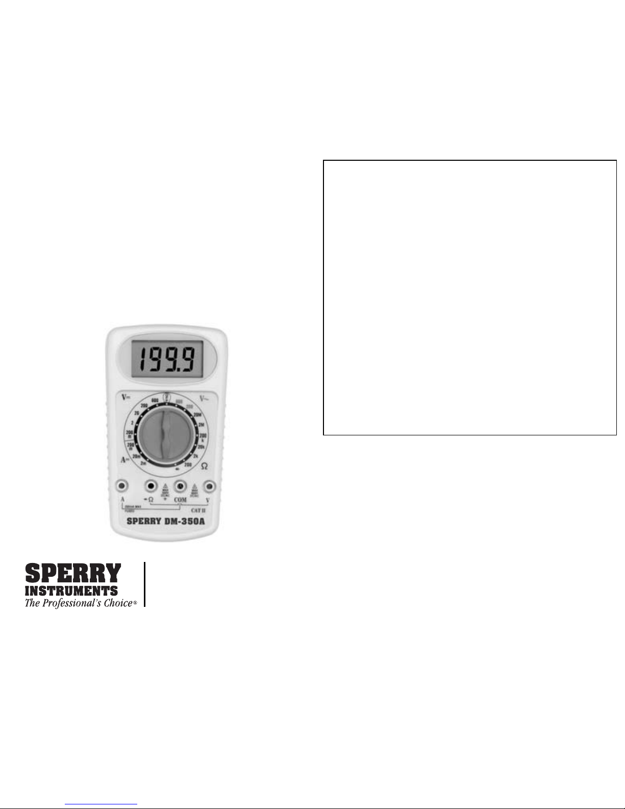
OPERATING INSTRUCTIONS
MODELS DM-350A, 360A, 370A
DIGITAL MULTIMETER
PLEASE READ THESE OPERATING
INSTRUCTIONS CAREFULLY
Misuse and or abuse of these instruments cannot be prevented by
any printed word and may cause injury and or equipment damage.
Please follow all these instructions and measurement procedures
faithfully and adhere to all standard industry safety rules and
practices.
2150 Joshua’s Path, Suite 302
Hauppauge, NY 11788
Phone:800-645-5398
www.sperryinstruments.com
WARRANTY RETURN
Refer to Section "Return for Repairs" for complete
instructions. All warranty returns must include a legible
copy or original of the sales receipt clearly identifying the
model number, serial number and date of purchase.
Sec. 1 DESCRIPTION
These DMMs offer a powerhouse of measurement
capability in a small self-contained housing. It is
designed for the professional at work in the field or in the
laboratory, yet simple enough to operate making it
perfect for the hobbyist too.
Safety was a prime consideration in the design of this
DMM.
Housed in shock resistant ABS plastic, this
instrument stands
up to the use and abuse of everyday
service, and electrically insulates the user from potential
shock hazards. Electronic overload protection against
accidental application of voltage to resistance and
1. Disconnect the test leads from any energized circuit
and then from the instrument.
2. Turn the range switch to the "OFF" position.
3. Remove screws and open the back case.
4. Remove the battery from the compartment and
unsnap the battery connector.
5. Replace the battery with a 9V transistor type battery
(NEDA #1604), AWS Part #B-4. For maximum battery
life, alkaline cells are recommended.
6. Reverse the above procedure to complete battery
damage, contamination (excessive dirt, grease, etc.) and
defects. Examine the test leads for cracked or frayed
insulation and make sure the lead plugs fit snugly into
the instrument jacks. If any abnormal conditions exist do
not attempt to make any measurements. Instead refer
to sec.14 Return for Repairs.
Sec. 8.1 VOLTAGE MEASUREMENTS
1. Insert the black and red test leads into the respective
"COM" and "V-Ω " jacks.
2. Place the range selector switch into the
600DCV/600ACV position if a dc voltage is to be
Page 2
Instrument complies with insulation category (over voltage
category) III. Industrial use. Pollution degree 2 in
accordance with IEC-664. Altitude up to 2000M. Indoor
use. If the equipment is used in a manner not specified,
the protection provided by the equipment may be
impaired.
DOUBLE INSULATION
WARNING: TO AVOID ELECTRIC SHOCK
DISCONNECT MEASURING TERMINALS
BEFORE REMOVING BATTERY COVER.
CAUTION: FOR CONTINUED PROTECTION
AGAINST FIRE, REPLACE ONLY WITH FUSE OF
THE SPECIFIED
VOLTAGE, CURRENT AND
RUPTURE SPEED RATINGS.
!
!
DC Voltage
25 Range, 7 Function 20 Range, 7 Function 17 Range
Function
DM-370A
DM-360A
DM-350A
Range
Basic
Accuracy
Resolution
Input
Impedance
Overload
Protection
200mV/2/20/
200/600V
1%
100 u V
10 M OHM
1100 VDC or
peak AC for
1 min
200mV/2/20/
200/600V
1.2%
100 u V
10 M OHM
1100 VDC or
peak AC for
1 min
200mV/2/20/
200/600V
2%
100 u V
10 M OHM
1100 VDC or
peak AC for
1 min
AC Current
For the DM-370A model only.
Range
20/m/20m/200mA/10A
Basic Accuracy
2%
Resolution
1 uA
Input Impedance
350 mVmax
Overload Protection
0.5A/250V FUSE mA input 10A Unfused,
11A for 30 sec.
Resistance
Function
Range
Basic
Accuracy
Resolution
Overload
Protection
RANGES:
continuity circuits, combined with it's rugged construction
make it durable and reliable instrument.
Sec. 2 FEATURES
• UL listed to both US and Canadian standards
• Pocket-size
• Simple operation
• True RMS Value Measurements (DM-370A)
• Recessed safety designed input terminals
• Overload protection on all ranges
• Diode test function
Sec. 3 SPECIFICATIONS
Display: 3-1/2 digit LCD, 0.625"
numerals, maximum
reading1999 with automatic
sign.
Overange Indication: "1" most significant digit
shows.
Sampling Rate: 3 times per second.
Operating Environment: 0° to 50°C (32° to 122°F),
Max RH 80% to 31°C
decreasing linear to 50% RH
at 40°C.
Storage Environment: -20° to 60°C (-4° to 140°F) at
<80% relative humidity.
Power Source: One (1) 9V Transistor Type
Battery AWS Part #B-4
(NEDA #1604).
Power Consumption: 30mW typical.
Battery Life: 200 hours typical with zinc
carbon.
Fuse: Part F-7; 0.5A, 250V,
5x20mm, fast acting.
Fuse: (DM-370) AWS Part F-31; 10A, 250V,
5x20mm, fast acting Ceramic.
Dimensions: 5.6"H x 3.1"W x 1.3"D
(143 x 79 x 33 mm).
Weight: Approximately 5.6 oz. (160g)
including battery.
are used to measure distorted waveforms such as
chopping, square of sawtooth waveform, a large amount
of measurement error will be introduced, thus making it
impossible to take accurate measurement of True RMS
values. The model DM-307A with True RMS capability
provides accurate measurement of True RMS values
regardless of the waveform. It also permits measurement
of AC only of AC plus DC coupled Current and voltage.
Here reference is made to the crest factor which is
defined to be the ratio of True RMS value to the peak
value as represented by the following formula:
CAUTION
The mA ranges are fuse protected. To avoid possible
electrical shock, instrument damage and/or equipment
damage do not:
1. Attempt to take mA current readings on circuits
having more than 200mA current flow.
2. Impress a voltage between the "COM" and "mA"
terminals exceeding 250Vac/dc. Some circuit
damage may result for voltages below 250Vac/dc.
3. Raise the "COM" terminal potential above 500V to
ground.
Page 3

DC Current
25 Range, 7 Function 20 Range, 7 Function 17 Range
Function
DM-370A
DM-360A
DM-350A
Range
Basic
Accuracy
Resolution
Input
Impedance
Overload
Protection
2m/20m/
200mA/10A
1.5%
1 uA
350 mVmax
0.5A/600V
FUSE mA
input
10A Unfused,
11A for 30 sec.
200u A/2m/
20m/200mA
1.5%
100nA
350 mVmax
0.5A/250V
FUSE mA
input
2m/20m/
200mA
1%
1 uA
350 mVmax
0.5A/250V
FUSE mA
input
Microwave Diode
For the DM-360A model only.
Instant Continuity
For the DM-370A and DM-360A models only.
Diode Test
25 Range, 7 Function 20 Range, 7 Function 17 Range,
Function
DM-370A
DM-360A
DM-350A
Test Currency
Test Voltage
1.0+/-.6mA
3.2V max
1.0+/-.6mA
3.2V max
1.0+/-.6mA
3.2V max
Resistance
25 Range, 7 Function 20 Range, 7 Function 17 Range
Function
DM-370A
DM-360A
DM-350A
Range
Basic
Accuracy
Resolution
Overload
Protection
200/2K/20K/
200K/2M/20M
1%
100m OHM
500VDC or AC
rms
Electronic
200/2K/20K/
200K/2M/20M
1.5%
100m OHM
500VDC or AC
rms
Electronic
200/2K/20K/
200K/2M/20M
1.5%
100m OHM
500VDC or AC
rms
Electronic
2/20/200/600V
1.5%
1 mV
10 M OHM
1100 VDC or
peak AC for
1 min
AC Voltage
25 Range, 7 Function 20 Range, 7 Function 17 Range
Function
DM-370A
DM-360A
DM-350A
Range
Basic
Accuracy
Resolution
Input
Impedance
Overload
Protection
200/600V
2%
100 mV
10 M OHM
1100 VDC or
peak AC for
1 min
200/600V
2.5%
100 mV
10 M OHM
1100 VDC or
peak AC for
1 min
to be measured. Connect the test leads to the device
(the red test lead is positive with respect to the black
test lead). When measuring a diode, connect the "VΩ" terminal to the anode. A reading of indicates an
overrange condition. This will occur with the test
leads open on all resistance ranges. If overrange
occurs
when taking a reading, switch to the next
highest range.
NOTE: On the diode test range, a [1] reading indicates a
resistance greater than 2K which normally means a
defective open circuit diode. Be certain the diode anode
Specify in writing that calibration is necessary. The
instrument will be returned to you normally within one
week. Estimates will be furnished upon request.
CAUTION
The following procedures should performed by persons
trained and qualified in electronics and electronic
equipment service. DO NOT attempt this procedure if
not qualified.
WARNING
Do not attempt calibration or service unless another
person capable of rendering first aid and resuscitation is
Sec. 4 SAFETY RULES
1. Read these operating instructions thoroughly and
completely before operating your DMM. Pay
particular
attention to WARNINGS and CAUTIONS
which will inform you of potentially dangerous
procedures. These instructions must me followed.
2. Always inspect your DMM, test leads and
accessories for any sign of damage or abnormally
before every use. If any abnormal conditions exist
(e.g. broken test leads, cracked cases, display not
reading, etc.),
do not attempt to take any measurements. Refer to
section 12 Return for Repair.
3. Never ground yourself when taking electrical
measurements. Do not touch exposed metal pipes,
outlets, fixtures, etc., which might be at ground
potential. Keep your body isolated from ground by
using dry clothing, rubber shoes, rubber mats, or any
approved insulating material.
4. Never touch exposed wiring, connections or any
live circuit conductors when attempting to take
measurements.
5. Never replace the protective fuse inside the DMM
with any other than the AWS Part number specified or
approved equal.
Page 4

GARANTÍA
GARANTÍA LIMITADA DE UN AÑO
A. W. Sperry Instruments, Inc. certifica que este instrumento
AWS fue cuidadosamente verificado e inspeccionado y que
está garantizado por el término de un (1) año desde la fecha
de adquisición por parte de comprador final original, y que el
instrumento no haya sido empleado erróneamente, dañado
por negligencia, reparación indebida o no autorizada, o por el
uso abusivo o contrario a las instrucciones de operación. Los
instrumentos y los comprobantes de la compra, en la forma
de una copia legible o el original de la boleta de venta que
6. Remember: Think Safety and Act Safely.
7. When testing for the presence of voltage, make sure
the voltage function is operating properly by reading
a known voltage in that range before assuming that
a zero reading indicates a no-voltage condition.
8. Calibration and repair should be performed by
qualified maintenance personnel only.
9. Do not attempt calibration or service unless another
person, capable of rendering first aid and
resuscitation is present.
10
. Do not install substitute parts or perform any
unauthorized modification of the instrument. Return
the instrument to SPERRY INSTRUMENTS for
service and repair to insure that safety features are
maintained.
11. To avoid electric shock use CAUTION when working
with voltages above 40Vdc or 20Vac. Such voltages
pose a shock hazard.
12.
Do not operate this instrument in an explosive
atmosphere (i.e. in the presence of flammable gases
or fumes, vapor or dust).
Sec. 5 PREPARATION FOR USE
Sec. 5.1 UNPACKING AND CONTENTS CHECK
The DM-350A comes complete and ready to use. Check
the following contents list when unpacking. If any pieces
are missing notify the distributor you purchased the
instrument from or A.W. Sperry Instruments, Inc.
• Operating Instructions #312
• Test Leads TL-76 (one black, one red)
• 9V Transistor Type Battery (AWS Part #B-4)
• One Fuse installed
Sec. 5.2 PRE-OPERATION PROCEDURE
1. Install the 9V transistor type battery.
2. Inspect the instrument for any external defects by
comparing with the diagram on page 1. If any
abnormal conditions exist, do not attempt to take any
measurements. Refer to sections 9 (Maintenance)
and 12 (Return for Repairs).
3. Insert the test leads into the "COM" and "V-Ω " jacks.
Connect the two ends of the test leads together.
4. Place the range selector switch into the off position.
Nothing will appear on the display. Place the range
selector switch into the following ranges shown in the
chart below. Check for the appropriate meter response.
Range Display Reading
600DCV 000 +/-4 digits
200DCV 00.0 "
20DCV 0.00 "
2DCV .000
200 1_ _.
2K 1.
20K 1_.
200K 1_ _.
5. As you can see, the decimal point moves as the
ranges are changed. The maximum display reading
is 1999. The 200DCV range will actually only read
199.9Vdc. We call this the 200DCV range for
convenience only.
6. You can now check the decimal point on each range
by referring to sec. 3 Specifications where the ranges
are all listed. Refer to the Range and Resolution
columns to compute the decimal point location.
7. If any abnormal conditions exist, do not attempt to
take any electrical measurements. Instead refer to
sec. 12 Return for Repairs.
Sec. 6 BATTERY REPLACEMENT
The DM-350A has a self-contained power supply
consisting of One 9V Transistor Type Battery (NEDA
#1604, AWS Part #B-4).
WARNING
Before attempting to replace the battery, first disconnect
the test leads from any energized circuit and then
disconnect the test leads from the instrument.
11/02 Formulario N° 312
INSTRUCCIONES DE
OPERACIÓN
MODELO DM-350A, 360A, 370A
MULTIMETRO DIGITAL
POR FAVOR LEA ESTAS
INSTRUCCIONES DE OPERACIÓN
CUIDADOSAMENTE
El mal uso o abuso de estos instrumentos no puede ser evitado
Page 5

2150 Joshua’s Path, Suite 302
Hauppauge, NY 11788
Phone:800-645-5398
www.sperryinstruments.com
1. Disconnect the test leads from any energized circuit
and then from the instrument.
2. Turn the range switch to the "OFF" position.
3. Remove screws and open the back case.
4. Remove the battery from the compartment and
unsnap the battery connector.
5. Replace the battery with a 9V transistor type battery
(NEDA #1604), AWS Part #B-4. For maximum battery
life, alkaline cells are recommended.
6. Reverse the above procedure to complete battery
replacement.
Sec. 7 FUSE REPLACEMENT
A 0.5A, 250V, 5 x 20mm fast acting fuse, AWS Part #F-7
is installed in the instrument and used to protect the
ampere ranges along with other solid state components.
Model DM-370A also has a 10A, 250V, 5x20mm
Ceramic, fast acting fuse.
WARNING
Before attempting to replace the fuse, disconnect the
test leads from any energized circuit and then
disconnect the test leads from the instrument. Replace
the fuse the AWS Part F-7 or approved equal only.
Always use fast acting, high interrupting type fuses
1. Disconnect the test leads from any energized circuit
and then from the instrument.
2. Turn the range selector switch to the "OFF" position.
3. Remove screws and open the back case.
4. Remove the fuse from the clip on the end of the PCB.
5. Install the replacement fuse being certain it meets the
AWS Part F-7 specifications.
6. Replace the back case.
Sec. 1 DESCRIPTION
These DMMs offer a powerhouse of measurement
capability in a small self-contained housing. It is
designed for the professional at work in the field or in the
laboratory, yet simple enough to operate making it
perfect for the hobbyist too.
Safety was a prime consideration in the design of this
DMM.
instrument stands
Housed in shock resistant ABS plastic, this
up to the use and abuse of everyday
service, and electrically insulates the user from potential
shock hazards. Electronic overload protection against
accidental application of voltage to resistance and
damage, contamination (excessive dirt, grease, etc.) and
defects. Examine the test leads for cracked or frayed
insulation and make sure the lead plugs fit snugly into
the instrument jacks. If any abnormal conditions exist do
not attempt to make any measurements. Instead refer
to sec.14 Return for Repairs.
Sec. 8.1 VOLTAGE MEASUREMENTS
1. Insert the black and red test leads into the respective
"COM" and "V-Ω " jacks.
2. Place the range selector switch into the
600DCV/600ACV position if a dc voltage is to be
measured or into the position if an ac voltage is to be
measured. Always start in the highest range of the
function to be measured.
CAUTION
To avoid possible electric shock, instrument damage
and/or equipment damage, do not attempt to take any
voltage measurements if the voltage is above 600Vdc or
if the voltage is unknown. 600Vdc is the maximum
voltages that this instrument is designed to measure.
The "COM" terminal potential should not exceed 600V
measured to ground.
3. Apply the test leads to the two points at which the
voltage reading is to be taken. Be careful not to
touch any energized conductors with any parts of
your body.
4. Turn the range selector switch to the next lower
range for a more accurate reading only if the reading
is within that next lower range.
5. When measurements are completed, disconnect the
test leads from the circuit under test. Remove the
test leads from the instrument.
True RMS Value Measurements (DM-370A)
Sec. 8 OPERATION
Before making any measurements always examine the
instrument and accessories used with the instrument for
resistente a los golpes, soporta el uso y el abuso del
servicio diario y a’sla electrónicamente al usuario de
riesgos de choque eléctrico potenciales. La protección
electrónica contra sobrecargas por aplicación accidental
de tensión a los circuitos para medición de resistencia y
continuidad, combinada con su construcción reforzada,
hacen de él un instrumento duradero y confiable.
Sección 2 CARACTERÍSTICAS
• Répertorié UL selon les normes américaines
et canadiennes
• Conçu pour la catégorie III 600 V
Most of the conventional Digital Multimeters (average
responding, calibrated in RMS of a sine wave) are
designed for sine waves of small distortion only. If they
Ambiente para almacenamiento
-20 a 60 °C con humedad
relativa inferior a 80%
Alimentación Una pila de 9 V, apta para
transistores, N° de pieza
AWS B-4 (N° NEDA 1604)
Requisitos de potencia Normal: 30 mΩ (típicos)
Vida útil de la pila Normal: 2000 horas con pila
de zinc-carbón
Fusible
N° de pieza AWS F-7; 0,5 A,
250 V, 5 x 20 mm, acción
Page 6

(NEDA #1604).
Power Consumption: 30mW typical.
Battery Life: 200 hours typical with zinc
carbon.
Fuse: Part F-7; 0.5A, 250V,
5x20mm, fast acting.
Fuse: (DM-370) AWS Part F-31; 10A, 250V,
5x20mm, fast acting Ceramic.
Dimensions: 5.6"H x 3.1"W x 1.3"D
(143 x 79 x 33 mm).
Weight: Approximately 5.6 oz. (160g)
including battery.
Overload
Protection
1100 VDC or
peak AC for
1 min
1100 VDC or
peak AC for
AC Current
For the DM-370A model only.
Range
Basic Accuracy
Resolution
Input Impedance
Overload Protection
20/m/20m/200mA/10A
2%
1 uA
350 mVmax
0.5A/250V FUSE mA input 10A Unfused,
11A for 30 sec.
1 min
1100 VDC or
peak AC for
1 min
are used to measure distorted waveforms such as
chopping, square of sawtooth waveform, a large amount
of measurement error will be introduced, thus making it
impossible to take accurate measurement of True RMS
values. The model DM-307A with True RMS capability
provides accurate measurement of True RMS values
regardless of the waveform. It also permits measurement
of AC only of AC plus DC coupled Current and voltage.
Here reference is made to the crest factor which is
defined to be the ratio of True RMS value to the peak
value as represented by the following formula:
Crest Factor =
Peak V
True RMS Value
alue
The crest Factor for model DM-370 is 3. This means that
a maximum voltage value to be measured is 3 times the
rated scale value of each range.
Sec. 8.2 CURRENT MEASUREMENTS
1. Insert the black and red test leads into the respective
"COM" and "mA" terminals.
2. Place the function switch to the 200mA position.
Always start with the highest range of the function to
be measured.
CAUTION
Do not attempt to take a current measurement if the
current is unknown or above 200mA. The "COM"
terminal potential should not exceed 500V measured to
ground.
3. Completely de-energize the circuit in which the
current is to be measured. Place the DMM in series
with the conductor carrying the current which is to be
measured. Energize the circuit.
CAUTION
Before changing ranges, always de-energize the circuit
completely. An open circuit exists between the test leads
during range change on the DMM.
CAUTION
The mA ranges are fuse protected. To avoid possible
electrical shock, instrument damage and/or equipment
damage do not:
1. Attempt to take mA current readings on circuits
having more than 200mA current flow.
2. Impress a voltage between the "COM" and "mA"
terminals exceeding 250Vac/dc. Some circuit
damage may result for voltages below 250Vac/dc.
3. Raise the "COM" terminal potential above 500V to
ground.
4. Energize the circuit. If the reading is within the next
lower range, switch to that range after completely deenergizing the circuit under test. Continue changing
to lower ranges if the reading is within the next lowest
range to obtain the best accuracy.
5. Completely de-energize the circuit before removing
the test leads.
Sec. 8.3 RESISTANCE AND DIODE MEASUREMENTS
1. Insert the black and red test leads into the respective
"COM" and "V-Ω" terminals.
2. Place the range selector switch into the Ω range
desired for a measurement. (The test range
measures resistance from 000 up to 1999 and is
used to test the forward resistance value of diodes.
The diode check entails injecting a given current into
the diode juction to be tested and reading the voltage
drop across the diode. Models DM-350A, DM-370A
CAUTION
All resistance and diode measurements should be taken
on de-energized circuits only. To avoid possible
electrical shock, instrument damage and/or equipment
damage do not connect the "COM" and "V-Ω " terminals
to circuits having a potential difference exceeding
250Vdc/ac. Do not connect the "COM" terminal to
potentials exceeding 500V to ground.
3. Completely de-energize the circuit or device which is
Tensíon Continua
Rango 26, 7 Funciones Rango 20, 7 Funciones Rango 17, 5 Funciones
DM-370A
Rango
Precisión
Básica
Resolución
Impedancia
de Entrada
Protección
Contra
Sobrecarga
200 mV/2/20/
200/600 V
1%
100 μ V
10 M OHMIOS
1100 VCC o CA
Pico por
DM-360A
200 mV/2/20/
200/600 V
1.2%
100 μ V
10 M OHMIOS
1100 VCC o CA
Pico por
DM-350A
200 mV/2/20/
200/600 V
2%
100 μ V
10 M OHMIOS
1100 VCC o CA
Pico por
Corriente Continua
Rango 26, 7 Funciones Rango 20, 7 Funciones Rango 17, 5 Funciones
DM-370A
Rango
Precisión
Básica
Resolución
Carga de
Tensión
Protección
Contra
Sobrecarga
2 m/20 m/
200 mA/10 A
1.5%
1 μA
350 mV máx
Entrada mA de
fusible 0.5 A/
DM-360A
200 μ A/2 m/
20 m/200 mA
1.5%
100nA
350 mV máx
Entrada mA de
fusible 0.5 A/
DM-350A
2 m/20 m/
200 mA
1%
1 μA
350 mV máx
Entrada mA de
fusible 0.5 A/
Page 7
 Loading...