


UTS 30
Single
System
Planning
Installation
Guide
Station
R
UP-9801 Rev. 2

This
document
contains
preparation. Therefore,
implemented
latest
availability,
contact
Sperry
No contractual
functional
It is
further
this
document,
it
by
any means
purpose
at
manual
information
please
your
local
reserves the
obligation
implementation
understood
the recipient
whatsoever,
without
prior
regarding
consult
Sperry
right
the
latest
it
may
distribution
levels
the
representative.
to
modify
by
Sperry
is
either
that
in
consideration
or
purchaser
nor
written
permission
information
contain
descriptions
time.
of
implementation
appropriate
or
revise
regarding
expressed
agrees
to
permit
from
available at
To
ensure
release
the
content
level, scope,
or
implied
of
the
receipt
not
to
such action
Sperry.
the
functions
you
have
and
functional
time
of
that
documentation
of
this
document.
or
this
document.
or
purchase
others,
timing
or
for
in
reproduce
by
of
not
the
or
of
of
copy
any
FASTRAND, SPERRY, SPERRY UNIVAC, UNISCOPE, UNISERVO,
UNIVAC are registered
FLOW-MATIC,
additional
MAPPER, PAGEWRITER, PIXIE, SPERRYLINK, and UNIS are
trademarks
trademarks
of
the
Sperry
of
the
Sperry
Corporation.
Corporation.
ESCORT,
and
© 1985 - SPERRY CORPORATION
PRINTED IN U.S.A.

SPERRY
6TH
FLOOR
8008
MCLEAN
This
library
Station
System
WESTPARK
VA
memo
announces
Installation
Z2
UAS
DRIVE
22102
the
release and
Planning Guide," UP-9801 Revision 2.
availability
of
Update
Package A
It
is a Standard
SPERRY®
UTS30
Single
System
Station
Installation
Planning Guide
for
"SPERRY UTS 30
Library
Item
Single
(SLI).
The UTS 30 is a low-cost, intelligent display terminal specially
receiving,
cartridge
SPERRY 8439 Double-Sided Diskette Subsystem. The
program
This update contains
30T desk station
various
This
representative.
manipulating,
that
is easily installed
products and user
through
configurations
book
is
included in
and displaying data. The
through a door
progammability
the
latest
information
the
8613 signal
of
Sperry
the
equipment
standard library
powerful
in
the
implemented
available
distribution
and the SL
for
the UTS
UTS 30 capabilities are
top
functions
through
for
connecting
module
1.
30.
tailored
of
the
of
the
and
Copies
in
two
different
terminal
the
low-cost 8439 diskette subsystem.
the
the
may
or
UTS 30 can be
UTS 30T single station and
Telecom SL 1 PBX. It also presents
also be ordered
provided
loaded
versions
from
further
by
for
by a program
diskette
enhanced
your
sending,
by
by
Model
Sperry
a
Lists MAC, MBR, MBSU, MCZ, MMZ,
8, 9, 9U, 10, 11, 18, 19, 20, 21, 30,
37, 37U, 38, 60, 61, 62, 63, 63U,
31U,
64, 64U, 65, 66, 75, 76, 77, 78, 81,
81U,83,83U,89,89U
Lists MCS, MCT, MZZ,
(30 pages
plus
library
82
memo)
Library
Memo
UP-9801 Rev.
May
1986
for
2-A

UTS30
SPERRY
6TH
FLOOR
8008
MCLEAN
This library memo announces
Planning
The
UTS
ceiving, manipulating, and displaying data. The powerful
cartridge
8439
Double-Sided Diskette Subsystem. The
and user
Revision 2 contains the latest
for
installation
peripheral equipment. This revision covers such items
considerations;
installation, and checkout
WESTPARK
DRIVE
VA
the
Guide." UP-9801 Rev. 2.
30
is
a low-cost,
that
is
easily installed
programmability
of
the
it
also defines general customer responsibilities under customer setup,
intelligent
implemented through the low-cost
information
UTS
30 Single Station and the
of
the equipment.
release and availability
It
is
a Standard Library Item (SLI).
display terminal specially tailored in
through a door
Z2
in the
functions
available
top
of
to
assist the customer in planning and making preparations
UAS
22102
of
"SPERRY UTS
UTS
30
capabilities
of
the terminal
the
UTS
30 can
8439
diskette subsystem.
SPERRYLINK
as
power and
SPERRY®
UTS30
Single
Station
System Installation
from
which
Guide
versions
diskette
for
sending, re-
by
a program
by
a SPERRY
by
program products
includes unpacking,
Planning
30
Single Station System Installation
two
different
are
provided either
or
loaded
be
further
Model 30 Desk Station and associated
space
enhanced
requirements and environmental
book
is
This
sentative.
Destruction Notice: This revision supersedes and
Planning
UP-9801 Rev. 1
Lists MAC, MCZ, MMZ,
18,
19,
61,
62, 63,
77,78,81,81U,83,83U,89,89U,MBSU,
MBR
included in the standard
Guide,"
20,
UP-9801 Rev. 1, released under
and/or
its
8,
21,
30,
31U,
63U,
64,
37,
64U,
library
9,
9U,
37U,
65, 66,
10, 11,
38,
75, 76,
memo.
60,
library
for
Lists MZZ, MCS, MCT,
(79
the
UTS
30. Copies may also
replaces
library
pages plus library memo)
"SPERRY
memo dated
82
be
ordered by
UTS
30 Single Station System Installation
April,
1984.
Please
your
Sperry repre-
destroy all copies
Library
UP-9801 Rev. 2
October
Memo
1985
of
for

SPERRY
UTS 30
Single
Station
System Installation
Planning Guide
This
document
preparation.
implemented
latest
information
availability,
contact
your
Sperry
reserves
No
contractual
functional
It is
further
this
document,
it
by
any
purpose
FASTRAND, MAPPER,
SPERRY
trademarks
PAGEWRITER, PIXIE, SPERRYLINK,
the
service
without
Sperry
marks
contains
Therefore,
at
manual
please
local
Sperry
the
obligation
implementation
understood
the
means
UNIVAC,
recipient
whatsoever,
prior
UNISCOPE, UNISERVO,
of
the
Corporation.
of
the
the
latest
it
may
distribution
regarding
consult
right
written
Sperry
levels
the
representative.
to
modify
by
Sperry
is
either
that
in
consideration
or
purchaser
nor
permission
=<>=SPERRY,
Sperry
USERNET, MAPPER,
Corporation.
information
contain
appropriate
to
Corporation.
descriptions
time.
of
implementation
or
revise
regarding
expressed
agrees
permit
from
SPERRY, SPERRY=<>=
UNIVAC
and
UNIS
To
the
or
of
such
Sperry.
are
available
ensure
release
content
level,
implied
the
receipt
not
action
and
ESCORT,
additional
and
to
at
the
time
of
functions
that
you
have
and
documentation
scope,
reproduce
by
=<>=
CUSTOMCARE
functional
of
this
document.
or
in
timing
this
document.
or
purchase
others,
are
registered
FLOW-MATIC,
trademarks
or
for
UNIVAC,
of
not
the
or
of
of
copy
any
of
are
© 1986 - SPERRY CORPORATION
PRINTED IN
U.S.A.

UP-9801 Rev.
2-A
SPERRY
UTS
30
SINGLE STATION
System Installation Planning Guide
PSS
1
Part/Section
Cover
Title Page
PSS
Contents
1
2
3
Page
Number
1,
2
3, 4
1
2,3
4, 5
6
1
thru
2
5
6
thru
9
thru
12thru
1
2
4
8
11
14
Update
Level
Orig.
A
A
Orig.
A
A
Orig.
A
Orig.
A
Orig.
A
Orig.
A
A*
A
Orig.
PAGE
STATUS SUMMARY
ISSUE: Update
Part/Section
Appendix
Appendix
Appendix
Appendix
Appendix
User
Sheet
H
I
J
K
L
Comment
A - UP-9801
Page
Number Level
1,
2
1, 2
1,
2 Orig.
1,
2 Orig.
1, 2
Update
Orig.
Orig.
Rev.
2
Part/Section
Page
Number
Update
Level
4 1
5
6 1, 2
7 1
8 1
9 1
Appendix
Appendix
Appendix
Appendix
Appendix
Appendix
Appendix
A
B 1, 2
C
D
E
F
G
2
1
8
3
1
1, 2
1, 2
1, 2
1, 2
1, 2
thru
thru
thru
thru
thru
A
Orig.
4
Orig.
7
A
Orig.
A
Orig.
Orig.
4
Orig.
3
Orig.
3
Orig.
Orig.
Orig.
Orig.
Orig.
*New
Pages
All
the technical changes are
technical changes begin
at
this line
denoted
line indicates a technical change in
changes in
both
lines
or
deletions.
by
an arrow (-+) in
and
continue
only
the
until
that
an upward
line. A horizontal arrow located
margin. A downward
pointing
arrow (
pointing
t)
between
arrow (
.J,)
next
to
is found. A horizontal _arrow(-+)
two consecutive lines indicates technical
a line indicates
pointing
that
to a

UP-9801 Rev. 2
CONTENTS
1.
INTRODUCTION
SPERRY UTS 30 SINGLE STATION
System Installation Planning Guide
Contents 1
Contents
1.1. GENERAL
1.2.
1.3. RELATED PUBLICATIONS
2.
COMMUNICATION CONFIGURATIONS
2.1. POINT-TO-POINT CONFIGURATIONS
2.2.
2.3. MULTIPLEXED CONFIGURATIONS
2.4. CASCADED CONFIGURATIONS
2.5.
2.6. UTS 30T AND SPERRYLINK MODEL 30T CONFIGURATIONS
2.7. UTS
3.
ENVIRONMENTAL CONSIDERATIONS
3.1. GENERAL
3.2. TEMPERATURE/HUMIDITY
3.3. ELECTROMAGNETIC
3.4. ELECTROSTATIC DISCHARGE
3.5. ELECTRICAL
3.6. LIGHTING
4.
POWER
SITE
MUL
TIDROP CONFIGURATIONS
MIXED CONFIGURATIONS
CONSIDERATIONS
.........................................................
PLANNING CONSIDERATIONS
...........................................
..........................................
30
X.25 PUBLIC DATA NETWORK CONFIGURATION
.........................................................
..........................................
INTERFERENCE
POWER
.........................................................
IMBALANCE
..................................
.................................
......................................
...................................
......................................
.................................
.......................................
...................................
............
..............
1-1
1-2
1-5
2-1
2-1
2-1
2-5
2-5
2-5
2-5
3-1
3-1
3-2
3-2
3-2
3-2
4.1. PRIMARY
4.2. VOLTAGE/FREQUENCY
4.3. BRANCH CIRCUIT CONSIDERATIONS
4.4.
POWER
POWER
RECEPTACLES
.................................................
...........................
.............................................
;
.................
.............................
·
...
4-1
4-1
4-2
4-2

Contents 2
5.
SPACE CONSIDERATIONS
SPERRY
System Installation Planning Guide
UTS 30 SINGLE STATION
UP-9801 Rev. 2
5.1. UTS 30 SINGLE STATION
5.2.
5.3. 8439 DOUBLE-SIDED DISKETTE SUBSYSTEM
5.4. MODEL
5.5. MODEL 258 PRINTER
5.6. MODEL
5.7. MODEL 35 PRINTER
5.8. 2712 DOCUMENT READER
5.9. 8609 TERMINAL MULTIPLEXER
5.10. 8610 DIRECT CONNECTION MODULE
5.11. 8613 SIGNAL DISTRIBUTION MODULE
5.12. DOPS/20 PROCESSOR
5.13. SPACE LAYOUT
5.14. SPACE LAYOUT
5.15.
6.
CABLING CONSIDERATIONS
7.
OTHER CONSIDERATIONS
7.1. UNPACKING/INSTALLATION. .
7.2. RELOCATION
MAGNETIC STRIPE READER
15
PRINTER
31
PRINTER
OF
UTS 30 SINGLE STATION
PRINTER
WITH
SPACE LAYOUT
AND
..........................................................
OF
UTS 30 SINGLE STATION
STAND
MODEL 35 PRINTER WITH STAND
.....................................................
OF
UTS 30 SINGLE STATION WITH MODEL 25B PRINTER
........................................................
..........................................
........................................
...............................................
..............................................
...............................................
...............................................
..........................................
......................................
AND
8441
MASS STORAGE SUBSYSTEM
......•.................................
.........................
................................
...............................
AND
MODEL 25B
AND
MODEL 35 PRINTER
..............................
........
5-1
5-2
5-2
5-3
5-4
5-5
5-6
5-7
5-7
5-8
5-8
5-9
5-10
5-11
5-12
7-1
7-1
8.
SITE PLANNING AND PREPARATION CHECKLIST
9.
TELEPHONE INTERFACE STATION (TIS) PLANNING CONSIDERATIONS
9.1. GENERAL
9.2. EQUIPMENT
9.3. RELATED PUBLICATIONS
. 9.4. SPACE AND LOCATION CONSIDERATIONS
9.5. ELECTROMAGNETIC INTERFERENCE
.............................................
......................................................
...........................................
.............
............................
~
...................
APPENDIXES
A. UTS 30 SINGLE STATION
B.
8439 DOUBLE-SIDED DISKETTE SUBSYSTEM
C.
MODEL 25B PRINTER
D.
MODEL
E.
MODEL 15 PRINTER
F.
MODEL 35 PRINTER
G.
8610 DIRECT CONNECTION MODULE
31
PRINTER
SUMMARY
SUMMARY
SUMMARY
SUMMARY
SUMMARY
DATA
DATA
DATA
DATA
DATA
SUMMARY
SUMMARY
DATA
DATA
·
............
9-1
9-1
9-2
9-2
9-3
H.
8609 TERMINAL MULTIPLEXER
SUMMARY
DATA

UP-9801
I.
Rev.
2-A
8613 SIGNAL DISTRIBUTION MODULE
SPERRY
System Installation Planning Guide
UTS 30 SINGLE STATION
SUMMARY
Contents 3
DATA
J. 2712 DOCUMENT
K.
DOPS/20 PROCESSOR SUMMARY DATA
L.
8441
MASS
STORAGE SUBSYSTEM
READER
SUMMARY
SUMMARY
DATA
FIGURES
1-1.
1-2.
2-1. Point-to-Point Communication Configurations
2-2.
2-3.
2-4. Cascaded Communication Configurations
2-5.
2-6.
2-7.
2-8.
2-9.
2-10
2-11. Configuration
2-12. UTS 30 in an X.25
4-1.
UTS 30 Single Station
UTS 30
Multidrop
Multiplexed
Mixed
Configuration
Configuration
Configuration
Series 1100 Host Computer
Configuration
the
Configuration
through
Power Plug Diagrams
with
Double-Sided Diskette Subsystem
Communication Configurations
Communication Configurations
Communication
of
of
SPERRYLINK Model 30T Desk Station
of
SPERRYLINK Model 30T Desk Station
of
UTS 30T Single Station
SDM
with
V.35
of
SPERRYLINK
SL 1 Using the V.35 SDM Interface
of
with
Configurations in UNISCOPE
UTS 30T Single Station
or
RS-232
SPERRYLINK Model 30T Deskstation
PDN
Configuration
....................................................
Peripherals
...............................................
Modem
Model
.....................................
with
with
......................................
30T Desktation
......................................
DATA
..............................
................................
...................................
..................................
...................................
Mode
a Host Processor
with a DCP
a Remote Host Processor
with a DCP
.................................
....................
with
through
a DOPS/20
and a
and Series 1100 Host
the
...............
........
through
SL1
.........
1-2
1-3
2-2
2-3
2-4
2-6
2-7
2-8
2-9
2-10
2-11
2-12
2-13
2-14
4-3
t
5-1.
5-2.
5-3. Dimensions
5-4. Dimensions
5-5.
5-6. Dimensions
5-7. Dimensions
5-8. Dimensions
5-9. Dimensions
5-10. Dimensions
5-11. Dimensions
5-12. Dimensions
5-13. Space Layout
5-14. Space Layout
5-15.
6-1.
6-2.
8-1.
Dimensions
Dimensions
Dimensions
Reader
Space Layout
with
Stand
Cable Feature Numbers
Configuration
Cable Feature Numbers
Configuration
Scale
of
of
of
of
of
of
of
of
of
of
of
of
..................................................................
Drawings
UTS 30/Model 30T Desk Station and Keyboard
Magnetic Stripe Reader
8439 Diskette Subsystem
Model 15 Printer
Model
Model
Model 35 Printer
2712 Document Reader
8609 Terminal
8610 Direct Connection
8613 Signal Distribution
DOPS/20 and
of
of
of
..............................................................
............................................................
............................................................
258 Printer
31
Printer
UTS 30 Single Station,
UTS
30
Sin~le
UTS 30
of
Sing~e
for
Connecting Components
for
Connecting Components
Equipment
...........................................
with
with
with
Multiplexer
8441
Station and Model 35 Printer
Station,
.............................................
.....................................
....................................
Stand
Stand
Stand
.....................................
Module
Module
Mass Storage Subsystem
Model
Model
...............................
.................................
.................................
...................................
..............................
........
258 Printer, and
258 Printer, and
of
a UTS 30
of
a SPERRYLINK
................
~
....................
..................
Magnetic
with
Stand
Model
35 Printer
Model
Stripe
......
30T
5-1
5-2
5-2
5-3
5-4
5-5
5-6
5-7
5-7
5-8
5-8
5-9
5-10
5-11
5-12
6-2
6-3
8-4
9-1.
Model
30
Desk Station
with
TIS Cartridge and Foot Pedal
....................
9-2

UP-9801 Rev.
2-A
SPERRY
System Installation Planning Guide
UTS 30 SINGLE STATION
1-1
1.1. GENERAL
This guide provides information on preparing
Terminal System 30 (UTS
Desk Station, the
the 8613 Signal Distribution Module (SOM), and the
•
SPERRY
•
SPERRY
•
SPERRY
•
SPERRY
SPERRY
8439 Double-Sided Diskette Subsystem
Model
Model 258 Printer
Model
15
31
30)
Single Station (figures 1-1 and 1-2), the SPERRYLINK Model 30
8609 Terminal Multiplexer, the 8610 Direct Connection
Printer
Printer
your
site
for
following
1.
installation
peripheral equipment:
Introduction
of
the
SPERRY
Universal
Module
(DCM),
,._
•
SPERRY
•
SPERRY
•
SPERRY
NOTE: The UTS 30 single station
with
an
module. In this guide, the single stations
be referred
(UTS 30T)
This
equipment
help you prepare
will
be packaged
will
provide installation
Sperry representative.
If
you plan
correctly
considerations, UP-11139, and the 8613 SOM installation/operation guide, UP-10897,
information
NO
TE:
contact
qualified
Model
2712 Document Reader
Magnetic Stripe Reader
RS-232-C
to
and
to
wired
about
If
you
Northern
Northern
35
Printer
processor module, an X.21 processor module,
as the UTS
the SPERRYLINK
is designed
your
site
with
the equipment.
for
attach the Model 30T
punch-down block in place before installing the SOM. See the twisted pair
twisted pair
plan
to configure
Telecom
Telecom personnel.
and
the SPERRYLINK
with
the RS-232-C
30.
The UTS 30 single station
Model
to
be
for
the equipment. The instructions
a fee. If you have any questions about
wiring
about
30T
desk station
unpacked, installed, and tested
If
you decide
to
the 8613 Signal Distribution Module, you
and punch-down block installation.
your
system using the Northern Telecom
planning
information.
not
Model
with
will
be
to
install the
All
SL
and
the
referred to as the
for
30 Desk Station are available
or a twisted
X.21
processor
twisted
installing and testing the units
1 installation
pair
by
the user. This guide
equipment
this
alternative, contact
pair
modules
processor
Model
yourself, Sperry
must
SL
1* PBX system,
must
be
processor
will
module
30T.
will
your
have a
wiring
for
more
done
by
*SL 1 is a registered trademark
of
Northern Telecom, Inc.
t

1-2
SPERRY
System
UTS 30 SINGLE STATION
Installation Planning Guide
UP-9801
Rev.
2
Figure
1-1.
UTS
30
1.2. SITE PLANNING CONSIDERATIONS
The
UTS
30,
conditions.
installation
Model
Normally,
and
30T, and
little
operation.
peripherals
or
no
In
planning
are
modification
your
factors:
•
The
•
communication
General
environmental
configuration
considerations,
you
are
3)
•
Power
•
Space
•
Cable
requirements,
for
and
placement
routing
(Section
including
of
the
6)
placement°
equipment
Single
designed
to
existing
site,
using
such
of
(Section
Station
with
to
site
however,
(Section
as
temperature,
power
receptacles
5)
Peripherals
operate
facilities
you
2)
under
is
necessary
should
humidity,
(Section
various
consider
and
lighting
4)
9801·1
environmental
for
successful
the
following
(Section

UP-9801 Rev. 2
SPERRY
System Installation Planning
UTS 30 SINGLE STATION
Guide
1-3
Before
following
your
factors:
• Cables
You
may
installing a
may
also need cable raceways
the
equipment.
•
Wiring
If
you
twisted
additional
wiring
equipment
need
to
number
For additional
are installing
pair
telephone
information
Figure 1-2. UTS 30
is installed,
route cables
of
UTS 30 single stations
information,
Model
30T desk stations,
lines
with
on the
with
you
through
or
similar
6-position
twisted
need
considerations manual, UP-11139.
Double-Sided
to
Diskette Subsystem
make
walls, ceilings,
at
various places
materials
refer
to
to
the
determine
wall
outlets
pair
wiring
requirements, refer
the
necessary preparations
or
false floors, especially
throughout
protect
applicable cable
loose cables
whether
wired
for
ordering
your
4-wire
facility
or
to
if
your
facility. You
that
interconnect
guides.
has standard
6-wire
the
twisted
9801-2
for
the
you
are
lines. For
pair

1-4
•
Equipment
If
you
to
order
to
operate
From Other Companies
are obtaining
and install
with
V.28 requirements at a
clear-to-send (CTS) signal
delay
of
not
less than 8 milliseconds
it
any
equipment
before any
modem
that
maximum
must
SPERRY
System Installation Planning Guide
UTS
(such
as
SPERRY
30
SINGLE STATION
modems)
equipment
from
another
company,
is installed. The UTS
UP-9801 Rev.
you
30
was designed
meets EIA* RS-232-C/CCITT** Recommendation V.24 and
of
9600 bits per second. The
be controlled
must
be
provided
by
the
request-to-send (ATS)
between the
only
requirement
ATS
and
signal
CTS
is
signals.
will
that
2-A
need
the
and a
The SDM
was
designed
Recommendation V.35 requirements at a
determined
If
you
for
information
t
• Storage Facilities
If
your
subsystem,
cartridges ready
by
connect
equipment
you
clock signals provided
your
SDM
about
compatible
configuration includes a
should have the necessary paper, diskettes,
for
use
additional storage facilities
• Operator Training
UTS 30/Model 30T desk stations have been designed
The
operator
familiar
information
When
the
training. However,
with
the
equipment
on the UTS 30 single station and
equipment
arrives,
• Unpack and inspect the equipment.
Sperry representative immediately.
to
operate
to
the
when
for
to
follow
with
any
SL 1
maximum
by
the
through
modem
modems.
the
that
meets EIA* RS-232-C/CCITT**
of
56000 bits per second. Data rates are
V.35 interface, contact
modems, couplers, etc.
printer
the equipment arrives. You
the
printer
supplies and
or
the
8439 double-sided diskette
print
wheels, and ribbon
should
the
reusable shipping containers.
also consider
to
require little
facilitate installation and checkout, operators
before
it
is delivered. Refer
the
SPERRYLINK
to
the
applicable
Model
30 desk station.
these procedures:
If
you find
any
damaged
or
missing items,
Northern
or
no
should
publications
notify
Telecom
providing
formal
become
for
your
• Install
communications
ready
•
Change factory-set operating parameters
the
UTS 30/Model 30T and peripherals, make the necessary cable connections
equipment, and install the cables
for
connection
by
Sperry personnel.
• Verify correct operation according
•
If
an
equipment
failure occurs, use the checkout procedures in
isolate and correct the problem.
If
you
•
relocation, and
*Electronic
**International
Industries Association
decide
to
Telegraph
relocate the equipment,
notify
your
Sperry representative.
and
Telephone Consultative Committee
(as
required) via keyboard entry.
to
the instructions in
follow
the
to
the
host
the
installation guide.
instructions
processor so
the
verification
provided
for
to
they
will
be
guide
to
repacking and

UP-9801
Rev.
2-A
1.3. RELATED PUBLICATIONS
SPERRY
System Installation Planning Guide 1-5
UTS
30
SINGLE STATION
Before
following
• UP-9796, SPERRY UTS 30 System Description
• UP-9355, SPERRY 8609 Terminal
• UP-9797, SPERRY UTS 30 Single Station
• UP-9798, SPERRY UTS 30 Single Station Operator's Reference
• UP-9799, SPERRY UTS 30 Single Station System Reference
• UP-9800, SPERRY UTS 30 Single Station Ordering Guide
• UP-10101,
• UP-9881, SPERRY
• UP-9884, SPERRY 8439 Double-Sided Diskette Subsystem
• UP-10201,
• UP-10699, SPERRY
you
begin planning
publications available
Preparation Guide
SPERRY
SPERRY
for
installation
for
reference:
UTS
30
Single Station Cable Ordering Bulletin
8439 Double-Sided Diskette Subsystem General Description
Model
Model
15
Printer General Description
15
Printer User Guide
of
the
Multiplexer
Introduction
UTS 30
and 8610 Direct Connection
or
Model
for
Operators
OperationNerification
30T,
you
should
Module
Guide
have
the
Site
• UP-10693, SPERRY Model 258 Printer General Description
• UP-10810, SPERRY Model 258 Printer User Guide
• UP-9868, SPERRY Model
• UP-11130,
• UP-11131,
• UP-10809,
• UP-9863, SPERRY Model 35 Printer General Description
• UP-10807,
• UP-10897,
UP-11139, Twisted Pair
•
following
The
SPERRYLINK
• UP-9751, SPERRYLINK Office System Model
SPERRY
SPERRY
SPERRY
SPERRY
SPERRY
publications are available
Model
30T Desk Station.
31
Printer General Description
Model
Model
Model
Model
8613 Signal Distribution
31
SCI
Printer General Description
31
SCI
Printer User Guide
31
Printer User Guide
35
Printer User Guide
Wiring
Considerations
to
Module
assist
30
(SOM) Installation/Operation Guide
you
in
Desk Station Installation Guide
efficient site
planning
for
f
f
the
• SL-0101, SPERRYLINK Office System
• PSL-0172, SPERRYLINK Office System Guide
Model
30 Desk Station
to
Documentation
Introduction

1-6
SPERRY
System Installation Planning
UTS
30
SINGLE STATION
Guide
UP-9801 Rev. 2
• UP-9349, SPERRYLINK Office System Concepts
• UP-9754, SPERRYLINK Office System DOPS/20 System Installation Planning Guide
• UP-9755, SPERRYLINK Office System DOPS/20 System Hardware Installation Guide
• UP-10897,
• UP-9873,
• UP-9875,
To
obtain
copies
SPERRY
SPERRY
SPERRY
of
8613 Signal Distribution
2712
Document
2712
Document
these publications, contact
Module
Installation and Operation
Reader General Description
Reader Installation and Operation Guide
your
Sperry representative.
Guide

UP-9801
Rev.
2-A
SPERRY
System Installation Planning Guide
UTS
30
SINGLE STATION
2-1
2.
The UTS
cascaded
through
Desk Station configurations are described
30
single station can be installed in point-to-point,
communication
configurations. These
2.5 and illustrated in figures 2-1
Communication Configurations
through
briefly
2-11.
2.1. POINT-TO-POINT CONFIGURATIONS
Point-to-point configurations (figure 2-1)
host
processor on a transmission line
30
is connected
directly
to
the
host processor
telephone transmission lines using modems.
not
allow
shared
multidrop,
configurations
2-5.
The UTS 30T and SPERRYLINK
are described
in 2.6 and illustrated in figures
direct
with
communication
by
another
UTS 30 (or
between a UTS 30 and a
similar
onsite transmission lines using DCMs,
multiplexed,
briefly
Model
2-6
and
in
2.1
30T
through
device). The UTS
or
with
2.2. MULTIDROP CONFIGURATIONS
Multidrop
transmission line
30
to
configurations (figure 2-2)
to
a host processor. A
the
transmission line.
allow
2.3. MULTIPLEXED CONFIGURATIONS
Multiplexed
the
UNISCOPE
multiplexer
terminal
multiplexer,
NOTES:
1.
When
required
time
2.
UTS
serial
configurations (figure 2-3)
mode
to
a single,
program
commonly
cartridge)
multiplexer, then directly
through a modem
including
for
is increased.
30
single
numbers
multiplexed
your
installation.
stations
lower
or
DCM, and then
cannot
than 8000.
allow
shared transmission line. Data travels
to
the host processor,
configurations
As
more
be
used
more
modem
to
or
up
to
be connected
to
the
in
devices
with
than one
DCM
must
16 basic UTS
through a fully
or
from
host
processor.
your
planning,
are
connected
SPERRY 8609
terminal
be used
30
to
share
to
connect each UTS
the
single stations (containing
configured
from
the
UTS 30
the
UTS 30
consider
to
multiplexers,
terminal
to a terminal
the access
the access
multiplexers
same
terminal
to
a
time
having

2-2
DIRECT CONNECTION
HOST
PROCESSOR
61
.M
(200
MAX.
SPERRY
UTS 30 SINGLE STATION
System Installation Planning Guide UP 9801 Rev. 2
MODEMS USED WITH
DCM'S
TRANSMISSION LINES
DCM
FT)
USED WITH IN-PLANT
IN-PLANT
TRANSMISSION
LINES
(SIGNAL
1524 M
MAX.
RATE
(NOTE
CABLES)
(5000 FT)
FOR TRANSMISSION
OF
3600
2)
TO
9600
BPS
TELEPHONE
TRANSMISSION LINES
TELEPHONE
TRANSMISSION
LINES
IANY
LENGTH)
8439
DISKETTE
SUBSYSTEM
8439
DISKETTE
SUBSYSTEM
NOTES:
1.
Up
to
two
Total length
not
One
2.
cable
meters
diskette subsystems can be connected
of
exceed 2.7 meters (9 feet).
printer
can
from
the UTS
(50 feet).
cable
be
UTS30
from
the UTS
connected
30
to
to
the
30
to
each
printer
to
the second diskette must
UTS 30. Total length
must
not
DCM
UTS
30
each
UTS
exceed 15.2
15.2 M
(50.0 FT)
30.
of
15.2 M
(50.0
FT)
(NOTE
2)
~ISKETTE
~
MODEL
258
3.
For
a transmission rate
maximum
mission rate
length
is
4572
MODEM
UTS
PRINTER
cable length
of
meters (15,000 feet).
of
is
2400 bits per second
3048 meters (10,000 feet).
15.2 M
(50.0
30
WITH
SUBSYSTEM
2400
to
FT)
15.2 M
(50.0
FT)
""
8439
~
~
MODEL
3600
bits per second (bps), the
or
less,
the
maximum
(NOTE
31
PRINTER
For
2)
a trans-
cable
9801-3
Figure
2-1.
Point-to-Point Communication Configurations

UP-9801 Rev. 2
CABLE A
DCM
(NOTE 1)
OR
MODEM
2)
(NOTE
SPERRY
UTS
30
SINGLE STATION
System Installation Planning Guide
HOST
PROCESSOR
16.2·M
(60.0 FT)
8439
DISKETT~
SUBSYSTEM
O~
MODEL
(NOTE
31
PRINTER
2-3
4)
CABLE
(NOTE 6)
NOTES:
1.
If
lines and
1524 meters
per second. For a transmission rate
second, the
transmission
cable length is 4572 meters (15,000 feet).
2.
If
transmission
3.
A diskette subsystem can be connected
length
exceed 2.7 meters
B
CABLE
C
CABLE
E
DCMs are used, cables A,
their
cumulative
(5000 feet)
maximum
rate
of
2400 bits
modems
are used, cables ·A,
lines and can be any length.
of
cable
from
(9
feet).
16.2 M
(60.0 FT)
DCM
OR
MODEM
(NOTE
DCM
OR
MODEM
(NOTE
5)
15.2 M
(60.0 FT)
5)
UTS 30
UTS 30 WITH 8439
DISKETTE SUBSYSTEM
DCM
OR
MODEM
(NOTE
15.2 M
(50.0 FT)
5)
UTS 30 WITH
DISKETTE SUBSYSTEM
B,
C,
D,
and E are
length
(A+
for
a transmission rate
length is 3048 meters (10,000 feet). For a
per
second
B,
the UTS
30
to
irfplant
B + C + D +
of
2400
or
C,
D,
·and
to
each UTS 30. Total
the
second diskette
transmission
E)
must
not
of
3600
to
9600 bits
to
3600 bits per
less, the
maximum
E are telephone
must
exceed
~
(NOTE
1-------~8439
8439
SUBSYSTEM
3)
(NOTE
(NOTE
DISKETTE
3)
~
41
DISKETTE
SUBSYSTEM
MODEL 25B PRINTER
8439
4.
One
printer
not
from
feet).
5.
Up
that
be arranged
cannot be
6.
T-connectors are required
modems
can be connected
the
UTS
30
to
three DCMs can be
can be
multidropped
with
multidropped
are used.
to
the telephone
the
printer
depends on
on
to
each UTS 30. Total length
must
not
exceed 15.2 meters (50
multidropped.
the same
when
The
telephone
company.
transmission
DCMs are used,
number
facilities and
DCMs and
line.
but
of
modems
modems
not
of
cable
must
when
9801-4
Figure
2-2.
Multidrop
Communication
Configurations

2-4
SPERRY
UTS 30 SINGLE STATION
System Installation Planning Guide
UP-9801
Rev.
2
HOST
PROCESSOR
1S.2 M
(50.0
DCM
IN-PLANT
TRAN°SMISSION
LINES
1524 M (5000
MAX.
TRANSMISSION
OF
3600
(NOTE
DCM
15.2 M
(50.0
,.
I I I
.....
DISPLAY
-----~---
UPTO
16
TERMINALS
FT)
FOR
FT)
TO
1)
FT)
RATE
9600
BPS
TERMINAL
MULTIPLEXER
1524 M
(5000
FT)
HOST
PROCESSOR
MODEM
I I I
~
UPT016
DISPLAY
TERMINALS
TELEPHONE
TRANSMISSION
LINES
(ANY
15.2
M
(50.0
FT)
1524
(5000
LENGTH)
M
FT)
1
TERMINAL
MULTIPLEXER
1524
M
(5000
FT)
HOST
PROCESSOR
UPTO
DISPLAY
8439
IN-PLANT
TRANSMISSION
LINES
1524
M
(5000
FT)
(NOTE4)
MAX.
I I
16
TERMINALS
DISKETTE
SUBSYSTEM
(NOTE
2)
MODEL
NOTES:
1.
For
a transmission rate
(bps),
the
feet).
For
less, the
feet).
2.
Up
to
two
UTS
30.
second diskette
35
PRINTER
(NOTE
3)
of
maximum
a transmission rate
maximum
diskette subsystems can
Total
length
must
2400
cable length
cable length
of
cable
not
Figure
UTS
DISKETTE
to
is
of
2400
is
4572
be
for
exceed
2-3.
30
WITH
SUBSYSTEM
3600
bits per second
3048
meters
bits per second
meters
connected
the UTS
2.7
meters (9
Multiplexed
8439
(10,000
or
(15,000
to
each
30
to
the
feet).
Communication
3.
4.
One
printer
length
of
exceed
15.2
For
SPERRY
troller
(CTMC)
second
or
(2500
feet)
Configurations
(50.0 FT)·
MODEL
31
(NOTE
can be connected
cable
from
the
meters (50
Communications
at
a transmission rate
higher, transmission line length
maximum.
UTS
feet).
to
30
to
Terminal
each
the
15.2
M
PRINTER
3)
UTS
printer
Module
of
4800
is
762
30.
must
bits
Total
not
Con-
per
meters
9801-5

UP-9801 Rev.
2-A
SPERRY
System Installation Planning Guide
2.4. CASCADED CONFIGURATIONS
UTS
30
SINGLE STATION
2-5
Cascaded
to
another
parameters
that
be reserved
multiplexer.
been
configurations
one
of
fully
configured.
terminal
that
apply
the
connections
for
the
Up
to
(figure
multiplexer
to a multiplexed
on
second
16
multiplexer.
terminals
2-4)
the
can
allow
which
configuration
terminal
Up
be
connected
one
or
more
is connected
apply
multiplexer
to
15
terminals
to
the
terminal
to
to
attached
multiplexers
the
transmission
a cascaded
to
the
can be connected
second
terminal
2.5. MIXED CONFIGURATIONS
Multidrop,
an
example
multiplexed,
of a mixed
and cascaded
communication
configurations
configuration.
may
be
intermixed.
2.6. UTS 30T AND SPERRVLINK MODEL 30T CONFIGURATIONS
The UTS 30T Single Station is connected
lines in
single stations
processor. The SPERRYLINK
Office Processing Station
the
The SOM
illustrate possible UTS 30T and
your
building
to
or
the
SPERRY Distributed
controls
the
through
lines
SPERRY 8613 Signal
Model
Model
30T Desk Station is connected
20
(DOPS/20)
Communications
data
flow
from
the
SPERRYLINK
to a host
of
the
SL 1 PBX system. The data is
Distribution
or
to
Processor (DCP)
the
desk stations
Model
processor
Module
the
SPERRY Series 1100
through
(SOM) and
through
to
the
host. Figures
30T
configurations.
to
the
to
line. The
configuration,
modem
to
(or
the
multiplexer,
Figure
the
existing
transferred
then
the
SPERRY
host
SDM
or
SDM and SL
2-6
be connected
same
except
DCM)
first
2-5
must
terminal
if
it
has
illustrates
telephone
from
the
to
the
host
Distributed
computer
through
via
2-11
1.
+-
+-
2.7. UTS 30 X.25
PUBLIC
DATA NETWORK CONFIGURATION
The UTS 30 single station, operating
(PSCS) can be connected
terminals
operate on one
are connected
of
the
(Austria and Germany),
TELENET
(U.S.A.). Figure
to a host
to
the
following
PDN
processor
through a modem.
networks: ARPAC (Argentina), AUSTPAC (Australia), DATEX-P
TRANSPAC (France), IBERPAC (Spain), PSS (United
2-12
illustrates
with
X.25 Packet-Switched
over
foreign
the
UTS 30 X.25
Communications
public
data
networks
The UTS 30 X.25 can be
PON
configuration.
Software
(PON). The
configured
Kingdom),
to
and


UP-9801 Rev. 2
SPERRY
UTS 30 SINGLE STATION
System Installation Planning
HOST
PROCESSOR
15.2 M
(~0.0
FT)
MODEM
OR
DCM
(NOTE 1)
1
@
CABLE
(NOTE
21
Guide
B
2-7
CASCADED
MULTIPLEXER
1524 M
(5000
FT)
-----
UP
DISPLAY
TO
16 SPERRY
TERMINALS
TERMINAL
1524 M
(5000 FT)
1524
(5000
M
FT)
MODEM
OR
DCM
(NOTE 3)
15.2 M
(50.0 FT)
TERMINAL
MULTIPLEXER
@
UP
TO
15 SPERRY
DISPLAY
CABLED
CABLE
E
(NOTE
21
MODEM
(NOTE 3)
M
15.2
(50.0
FT)
UTS30
TERMINALS
OR
DCM
(NOTE 2)
@
1524
(5000
15.2 M
(50.0
UTS40
M
FT)
MODEM
OR
DCM
(NOTE 3)
FT)
UTS
30
WITH
DISKETTE
NOTES:
1.
When
the
with a common
transmission
2.
For DCMs, total length
exceed 1524 meters (5000 feet)
9600
per second,
a
cable length is 4572 meters (15,000 feet).
DCM is used, connection is
lines are telephone lines.
bits
per
second. For a transmission rate
transmission
the
8439
SUBSYSTEM
primary
power
of
maximum
rate
of
2400 bits per second
all cables
length is 3048
Figure 2-5.
made
source.
for a transmission
within
When a modem
(A+
B + C + D +
meters
or
Mixed
UTS
400
3.
Up
to
a single
is used, the
E)
must
rate
of
of
2400
to
3600 bits
(10,000 feet). For
less,
the
maximum
building
not
3600
to
4.
three DCMs can be
that
can be
be arranged
cannot be
T-connectors are
multidropped
with
multidropped
depends on
the telephone company. DCMs and
on the same
not
required
Communication Configurations in UN/SCOPE
multidropped.
with
telephone
transmission
modems.
Mode
UTS40
The
number
facilities and
line.
of
modems
modems
must
9801-7

2-8
SPERRY UTS 30 SINGLE STATION
System
Installation
Planning
Guide
EXISTING
TELEPHONE
LINES
UP-9801 Rev. 2
HOST PROCESSOR
UP
TO 24 SINGLE
STATIONS
UTS 30T
PUNCH
DOWN
BLOCK
SDM
8439
DISKETTE DRIVE
(OPTIONAL)
2712
DOCUMENT
READER
(OPTIONAL)
Figure
PRINTER
(OPTIONAL)
2-6.
Configuration
of
UTS
30T
Single
Station
with a Host
9801-8
Processor

UP-9801 Rev.
2-A
SPERRY UTS 30 SINGLE STATION
System Installation Planning Guide
EXISTING
TELEPHONE
LINES
2-9
DOPS/20
UP TO
DESK
PUNCH
DOWN
BLOCK
SOM
24
STATIONS
8439
DISKETTE DRIVE
(OPTIONAL)
2712
DOCUMENT
READER
(OPTIONAL)
Figure
2-7.
PRINTER
(OPTIONAL)
Configuration
of
SPERRYL/NK
Model
30T
Desk
Station
With a DOPS/20
and
9801·30
a DCP

2-10
SPERRY UTS 30 SINGLE STATION
System Installation Planning Guide
EXISTING
TELEPHONE
LINES
UP-9801 Rev. 2
SERIES 1100
HOST
MODEL 30T
DCP
PUNCH
DOWN
BLOCK
SOM
UP TO 24 DESK
STATIONS
2712
DOCUMENT
READER
(OPTIONAL)
Figure 2-8. Configuration
~
PRINTER
(OPTIONAL)
of
SPERRYLINK
8439
DISKETTE DRIVE
(OPTIONAL)
Model
JOT Desk Station
with
a DCP
and
a Series 1100 Host
~A01·10
Computer

UP-9801 Rev.
2-A
SPERRY UTS 30 SINGLE STATION
System Installation Planning Guide
EXISTING
TELEPHONE
UP TO
24 SINGLE
STATIONS
LINES
PUNCH
DOWN
BLOCK
HOST PROCESSOR
V.35 OR
RS-232
MODEM
V.35
OR
RS-232
MODEM
2-11
2712
DOCUMENT
READER
(OPTIONAL)
Figure 2-9. Configuration
,
..
-=
UTS 30T
~
~
PRINTER
(OPTIONAL)
of
Through the SDM With V.35
UTS 30T Single Station With a Remote HOST Processor
8439
DISKETIE DRIVE
(OPTIONAL)
or
RS-232
SOM
98111·31
Modems

2-12
SPERRYUTS 30 SINGLE STATION
System Installation Planning Guide
EXISTING
TELEPHONE
LINES
SL1
UP-9801
ADM
Rev.
2-A
SERIES 1100
HOST
DCP
UP TO 24 DESK
STATIONS
MODEL 30T
V.35
INTERFACE
PUNCH
DOWN
BLOCK
SOM
8439
DISKETTE DRIVE
(OPTIONAL)
DOCUMENT
(OPTIONAL)
*Northern
2712
READER
Telecom
Figure 2-10. Configuration
Equipment
~
PRINTER
(OPTIONAL)
of
SPERRYL/NK
Through an
Model
30T
Deskstation With a
SL
1 Using the V.35 SOM Interface
DCP
and
Series
1100
9801-32
Host

UP-9801 Rev.
2-A
SPERRY
System Installation Planning Guide
UTS
30
SINGLE STATION
TELEPHONE
EXISTING
LINES
2-13
DESK
(SEE
DESK
DESK
STATION
NOTE)
STATION
STATION
MODEL 30T
MODEL 30T
---------
DESK
STATION
....
1100
HOST
~
SL1*
DCP
1
2712
DOCUMENT
READER
(OPTIONAL)
*
Northern
NOTE: The
Telecom
Figure 2-11. Configuration
Equipment
number
PRINTER
(OPTIONAL)
of
deskstations is limited
of
DISKETIE
(OPTIONAL)
only
by
SPERRYLINK
8439
number
Model
DRIVE
30T
of
lines in
the
SL1.
Desk Station Throughthe
SL
9801
33
-
1

2-14
SPERRY
System Installation Planning Guide
UTS 30 SINGLE STATION
HOST
PROCESSOR
MODEM
Gb
UP-9801 Rev.
2-A
MODEM
UTS 30
PUBLIC
0
DATA NETWORK
MODEM
UTS 30
0
--
-
!/
/;
\
..
-
M
MODE
)~
i
"11
UTS30
9801-11
Figure 2-12. UTS 30 in an X.25 PON Configuration

UP-9801 Rev.
2-A
SPERRY
System Installation Planning Guide
UTS 30 SINGLE STATION
3-1
3.
Environmental Considerations
3.1. GENERAL
The UTS
associated peripherals, can operate efficiently in a
However, you should avoid installing this equipment in
• Kitchens, air-conditioner exhaust areas,
• Workshops
• Basements
30
single station and
or
similar
or
similar
the
SPERRYLINK Model 30T desk station, along
or
similar areas having exceptionally high
areas producing high levels
areas susceptible
to
flooding
3.2. TEMPERATURE/HUMIDITY
wide
the
of
dust and
range
following
of
grit
with
their
environmental conditions.
areas:
humidity
Optimum
(60
should
form
The type
UTS 30/30T 113 130
8439 diskette subsystem (per drive} 9.7
Model 15 printer
Model 258 printer
Model
Model
8610 terminal multiplexer
(maximum
8609 direct connection module
8613 signal distribution
2712
NO
TE:
requirements
temperature and
to
90
degrees Fahrenheit) and
not
exceed
on
or
in the equipment.
of
cooling and the
31
printer
35
printer
configuration)
document
Contact Northern Telecom, Inc.,
reader
for
11.1
the
SL
humidity
degrees Celsius
maximum
module
1 system.
conditions
20
to
(20
heat dissipation
for
70
percent relative
degrees Fahrenheit) per hour,
Heat Dissipation
kcal/hr
for
information
this
equipment
of
this
watts
86 100
86 100
81
258
65
10.3
51.4
86 100
about
equipment
11
94
300
75 Convection
12·
60
are 16
humidity.
cooling
to
32 degrees Celsius
Temperature changes
as
condensation
are as
follows:
Type
Cooling
Fan
Convection
Fan
Convection
Fan
Fan
Convection
Fan
Fan
and
of
heat
may
dissipation

3-2
SPERRY
System Installation Planning Guide
UTS 30 SINGLE STATION
3.3. ELECTROMAGNETIC INTERFERENCE
UP-9801
Rev.
2
Although
should
close
• Electromagnetic fields radiating
• Industrial
• Three-phase
electromagnetic
plan
your
to
the
following:
or
electric
equipment
equipment
power
motors
and generators
interference (EMI)
layout
to
from
such
as
arc welders and
distribution
lines and related
minimize
radio
3.4. ELECTROSTATIC DISCHARGE
High electrostatic charges can accumulate
carpeting
charges are transferred
equipment
static
or
other
is located. Use
problems.
floor
coverings. Interference
to
metal
of
antistatic
equipment
floor
coverings
3.5. ELECTRICAL POWER IMBALANCE
Power
disturbances can
stations,
distribution
is connected
to
transformer
imbalance
the
host, then
Model
30T desk stations, and
transformer
directly
and
must
(grounding
damage
and
to
the
the
host
and
share
voltage differential) caused
equipment
components. To
their
must
share the same earth
host
or
if
terminal
multiplexers
the
same earth
ground
will
not
cause
interference.
or
television
insulation
distribution
when
with
parts,
people,
equipment
or
to
or
commercial
by
prevent
peripherals receive
ground
multiplexers
must
be
powered
are used in
system as
problems
Avoid
in
most
installing
installations,
equipment
antennas and radar installations
testers
panels, electric heating units,
equipment,
operation
the
desk
antistatic sprays
lightning
or
can result
or
table
or
other
furniture
on
when
which
will
contact
these
reduce
serious electrical
such damage, UTS 30 single
system.
from
the
power
UTS 30
the
from
the
same
If
a UTS 30/Model 30T
the
communications
same
or
power
Model
distribution
30T.
power
you
too
the
line
If
the
host
and
the
UTS 30/Model 30T are
transformers
internal DCMs,
or
will
or
not
DCMs
share
must
the
same earth
be used
3.6. LIGHTING
The UTS 30/Model 30T is designed
office
filter
The
environments.
to
reduce glare.
display
unit
The screen is etched and
Light
should
should
be oriented
be balanced,
to
to
for
avoid
to
isolate
use
under
direct
be
powered
ground
the
power
average
the
faceplate is
however,
sunlight
from
system, then
systems.
lighting
equipped
to
minimize
or
shadows
different
modems,
conditions
power
multiplexers
found
with
a neutral-density
distribution
in
distractions and eyestrain.
on
the
screen.
with
most

UP-9801 Rev.
2-A
SPERRY
System Installation Planning Guide
UTS
30
SINGLE STATION
4-1
4.1. PRIMARY
For
domestic
60-Hertz, single-phase power source. Equipment
60-Hertz
Primary
power
100
volts
120
volts
220
volts
240
volts
input
UTS 30/Model 30T
8439 diskette subsystem (per drive)
Model
Model 258 printer
Model
Model 35 printer
8609
terminal
8610 direct connection
8613 signal distribution
2712
document
POWER
use, the UTS 30/Model 30T and associated
and can be ordered
ac,
single phase
ac,
single phase
ac, single phase
ac,
single phase
power
15
31
requirements
printer
printer
multiplexer
reader
module
module
for
for
use
with
this
equipment
4.
for
any
Power Considerations
equipment
international use is designed
of
the
following
are as
follows:
0.13 kVA
0.02 kVA
0.10 kVA
0.10 kVA
0.15 kVA
0.22 kVA
0.07 kVA
0.01
0.06 kVA
0.25 kVA
are designed
voltages:
kVA
for
a 120-volt,
for
50-Hertz
or
NOTES:
1.
The 8439 diskette subsystem obtains
power
from
the UTS 30
desk station.
2.
Contact
Nothem
Telecom, Inc.
for
information
about
power
4.2. VOLTAGE/FREQUENCY
The UTS 30/Model 30T and associated equipment are designed
significant variations
concerning
voltage
that
may
occur in
or
frequency variations, contact
input
voltage and frequency.
your
power
company.
or
SPERRYLINK
requirements
to
operate effectively despite
If
for
SL
1 system.
you
have questions
Model
30T
......

4-2
SPERRY UTS 30 SINGLE STATION
System Installation Planning Guide
UP-9801 Rev. 2
Acceptable
Nominal
100
120
220
240
Acceptable
Nominal
50
60
volts
volts
volts
volts
Hz
Hz
input
voltage
Voltage
input
frequency
Frequency
variations:
Voltage
88
102
187
204
variations:
Frequency
49.0
58.8
4.3. BRANCH CIRCUIT CONSIDERATIONS
Generally,
outlets.
data
equipment
Data
powered
equipment
connected
circuits
must
you
can
connect
However,
random
transmission.
at
your
site
communications
from
the
same branch
(coffee pots, fans, calculators,
into
the
should
also be
be separately fused
properly
the
UTS
30/Model
or
transient
To
avoid
for
equipment
this
power.
circuit
problem,
such as
as
branch circuits used
or
equipped
grounded.
electrical
modems
the
or
for
your
Limits
to
110
volts
to
127
volts
to
233
volts
to
254
volts
Limits
to
51.0
Hz
to
61.2
Hz
30T and associated
noise
use branch
in
and
the
circuits
direct
peripherals
power
connection
circuit
may
dedicated
to
to
modules
UTS 30/Model 30T and peripherals.
other
electromechanical devices)
data
communications
with
appropriate
circuit
equipment.
breakers. These
existing
cause
the
errors
electronic
may
However,
should
The
circuits
power
in
be
other
not
be
branch
If
you
are
modifying
and ordinances.
4.4. POWER
As
part
of
the
equipment. A power
Model
signal
the
For
has a
wire
4--1
green/yellow
any
30T,
distribution
terminal
domestic
NEMA
is
for
and
questions
RECEPTACLES
your
the
multiplexer.
use, each
5-15P
ground.
figure
wire
concerning
power
circuits
or
adding
site planning, make sure
cord 2
meters
8439 diskette subsystem,
module. A power
power
3-prong plug
For
international
4--1
).
For
power
in the
power
selection
cord
for
(figure
use,
cords
cord
of
cord 1.5
the
without
is
the
new
you
have
(6.6 feet) in
the
printers,
meters
UTS
30/Model
4--1
),
which
specify
the
plugs,
connected
correct
plugs,
ones, be sure
enough
length
the
power
will
direct
(5.0 feet) in
30T
and
is used in
plug
required
3-wire
make certain
to
ground
contact
in
your
you
comply
with
local codes
receptacles located close
be
supplied
connection
length
will
with
the
module,
be
supplied
UTS 30/
and
with
associated peripheral devices
for
the
power
your
that
power
Sperry
circuits
locality
during
installation
circuit.
(refer
If
representative.
where
to
you
one
table
have
to
the
the

UP-9801 Rev. 2
SPERRY
System Installation Planning Guide
UTS 30 SINGLE STATION
4-3
A
c
E
125V
15A
250V
13A
NEMA
BS
1363: 1967
5-15P
B
IEC 83/C5
D
250V
10A
SEV 1011
250V
6A
NEMA
Figure ~ 1.
6-15P
Power
9355-6
Plug Diagrams

4-4
Table
SPERRY
System
4-1.
UTS
30 SINGLE STATION
Installation
International
Planning
Plug
Requirements
Guide
UP-9801 Rev. 2
Country
Algeria
Australia
Austria
Belgium
Bulgaria
Canada
Denmark
Finland
France
Germany
Hong
Kong
Hungary
Voltage
250 v
250 v
250 v
250 v
250 v
v
125
250 v
250 v
250 v
250 v
250 v
250 v
250 v
Plug
(See Fig.
None*
No
cable
or
plug
B
B
B
A
E
None*
B
B
B
c
B
4-1)
Country
Malaysia
Netherlands
New
Zealand
Norway
Poland
Portugal
Rumania
South
Africa
Spain
Sweden
Switzerland
United
Kingdom
Voltage
250 v
250 v
250 v
250 v
250 v
250 v
250 v
250 v
250 v
250 v
250 v
250 v
Plug
(See Fig.
B
B
No
cable
or
plug
B
B
B
B
None*
None*
B
D
c
4-1)
Iceland
Indonesia
Iran
Ireland
Italy
Japan
Korea
*Cable
purchased
without
250 v
250 v
250 v
250 v
250 v
125 v
125 v
power
plug.
Plug
None*
must
B
B
B
B
A
A
be
added
United
Yugoslavia
Eastern
Some
Ireland
Middle
Some
East
Countries
by
customer.
States
Europe
of
Southern
East
Middle
125 v
250 v
250 v
250 v
250 v
250 v
250 v
A
E
B
None*
c
None*
c

UP-9801 Rev. 2
SPERRY
System Installation Planning Guide
UTS 30 SINGLE STATION
5-1
The
way
you
plan
your
space
or
the
SPERRYLINK
system. The UTS 30 is available
cartridge,
a
downline
subsystem.
The
with a program
downline
subsystem.
help
To
briefly
for
this
30
single
and
the
load
SPERRYLINK
load
you
plan
in
the
following
equipment
station
Model
programmable
only
version designed
Model
cartridge,
only
and
30T desk
version designed
your
space requirements,
paragraphs and in figures 5-1
are
summarized
the
Model
will
30T desk station, and
the
programmable
258 and
depend
in
UTS 30 used
station
in
on
two
versions:
to
operate
is available
to
operate
the
appendixes.
Model
5.
the
the
with
Model
the
dimensions
35
printers
Space Considerations
configuration
additional
the
a diskette
without a program
in
three
30T used
without a program
through
Work
of
your
UTS 30
equipment
basic UTS 30 used
subsystem.
versions:
with
a diskette subsystem, and a
of
the
5-12.
The technical specifications
space
are
shown
layout
in
you
The UTS 30T
cartridge
the
basic
cartridge
equipment
examples
figures
single
select
with a program
or
Model
or
are described
5-13
station
for
your
provides
a diskette
30T used
a diskette
for
the
and
5-14.
UTS
5.1. UTS 30 SINGLE STATION
The UTS 30
keyboard
side
of
single
(figure
the
UTS 30, and a
-·---
I
station
5-1
). A minimum
minimum
41.4
CM
(16.2
IN.)----1•~
Figure
5-1.
or
the
Dimensions
Model
30T desk station consists
of
10.2 centimeters (4.0 inches) clearance is
of
11.4 centimeters (4.5 inches) is
of a display
I
·~~~~
of
UTS
30/Model
'-~
~(21.0IN.)
30T
Desk
Station
53.3CM~
and
unit
required
recommended
Keyboard
and detached
on each
at
the
rear.
9801-30

5-2
SPERRY
System Installation Planning
UTS 30 SINGLE STATION
Guide
UP-9801 Rev. 2
5.2. MAGNETIC STRIPE
The
magnetic
5-2).
In
accommodate
almost
stripe
all
the
magnetic
work
reader
areas
READER
is a
small
there
stripe
reader.
device
will
be
requmng
ample
~
21.6~M
(8.5
IN.)
Figure
5-2.
Dimensions·
5.3. 8439 DOUBLE-SIDED DISKETTE SUBSYSTEM
The SPERRY 8439
A clearance
inserting
the
and
rear.
of
38.1
removing
Double-Sided
centimeters
the
diskettes. A clearance
Diskette
(15 inches) is
Subsystem
11.1
CM
(4.4
IN.)
of
Magnetic
{figure
required
of
no
special space
space
I
Stripe
5-3)
at
the
10.2
centimeters
on
either
Reader
can be used
front
of
considerations
side
of
9801-13
on
the
diskette
(4 inches) is
the
UTS
a desk
or
subsystem
required
{figure
30
to
table.
for
at
Figure
5-3.
Dimensions
of
8439 Diskette
Subsystem

UP-9801 Rev. 2
SPERRY
System Installation Planning Guide
UTS 30 SINGLE STATION
5-3
The UTS 30 and Model 30T desk stations can be used
and 35)
interface cartridge,
be used
paper. The
paragraphs and illustrated in figures
5.4.
The
or
on
MODEL
Model
a correspondence-quality
your
a desk
or
dimensions
UTS 30
a table,
of
or
or
on specially designed stands
each
printer
15 PRINTER
15
printer
(figure 5-4) is a small desktop printer
printer
Model 30T
with
5-4
through
(Model
its stand are
with a dot-matrix
31
will
support
5-7.
the stand occupies a space 39.6 centimeters (15.6 inches)
deep. The stand has
the back
while
printouts
room
underneath
for
a 4-inch stack
accumulate on the desk behind the printers.
printer
).
If
you
have
(Models 15, 258,
the
RS-232 peripheral
a second printer. The printers can
that
wide
of
facilitate
briefly
with
described in
a mini-stand. The
and 40 centimeters (15.7 inches)
paper
to
be fed
bottom
into
the
the
printer
loading
following
printer
from
of
on
\
9801-15
Figure 5-4-.
Dimensions
of
Model
15
Printer

5-4
SPERRY
System Installation Planning Guide
UTS
30
SINGLE STATION
UP-9801 Rev. 2
5.5. MODEL
The
Model
258
258
printer
PRINTER
(figure
5-5)
is
normally
occupies a space 61.2 centimeters (24 inches)
stand has a
accumulate
for
power
centimeters
slot
for
paper
on
the
shelf
behind
cords. A clearance
(6
inches) is needed at
to
feed
into
the
printer. A second
of
38.1
centimeters (15 inches) is needed at
the
sides
the
of
used
wide
printer
the
printer.
with
its
and 81.3
from
slot
at
own
stand. The
centimeters
the
bottom
the
rear
of
printer
on
the
(32 inches) deep. The
shelf
while
the
stand provides access
the
printouts
rear and 15.2
stand
74.0 CM
(29.0 IN.)
Figure
5-5.
Dimensions
of
Model
258
Printer
with
9801-16
Stand

UP-9801 Rev. 2
SPERRY
System Installation Planning Guide
UTS
30
SINGLE STATION
5-5
5.6. MODEL
The
Model
own
stand. The stand has a
printouts
accommodates
31
31
correspondence-quality
accumulate
three cut-sheet feeders.
PRINTER
on
the
slot
top
for
or
paper
of
the
graphics
to
printer
feed
stand behind
59.0
-(23.2
into
CM
IN.)
(figure
the
-
printer
the
printer. The
5-6)
from
is
normally
the
bottom
Model
used
shelf
31
with
while
printer
its
68.9 CM
IN.)
(27.0
Figure
~6.
Dimensions
of
Model
31
Printer
with
Stand
40.2
(15.75
9801-17
CM
IN.)

5-6
SPERRY
System Installation Planning Guide
UTS
30
SINGLE STATION
UP-9801 Rev. 2
5.7. MODEL 35
The
an
optional
shelf
the
Model
rear
while
of
35
alphanumeric
printer
printouts
the
stand
PRINTER
and
graphics
stand. The stand has a
accumulate
provides
on
access
the
for
printer
slot
top
power
for
of
the
cords.
(figure
paper
stand
5-7)
to
can be used
feed
into
behind
the
the
on
printer
printer.
a desktop
from
the
A second
or
on
bottom
slot
at
68.9 CM
IN.)
(27.0
Figure 5-7.
Dimensions
of
Model
35
Printer
with
Stand
40.2
CM
(15.7 IN.)
9801-18

UP-9801 Rev. 2
SPERRY
System Installation
UTS
30
SINGLE STATION
Planning Guide
5-7
5.8. 2712 DOCUMENT
The 2712
into
should
openings
document
·the SPERRYLINK system. The
be
unobstructed
(both sides) and any
READER
reader (figure
with a minimum
surrounding
Figure 5-8.
5-8)
document
Dimensions
5.9. 8609 TERMINAL MULTIPLEXER
is a device
for
entering
reader can be installed
of
9 centimeters
structure.
of
2712
Document
(3
inches)
typed
Reader
documents
on
a desk
between
9801·19
automatically
or
table. The fan
the
fan and
vent
The 8609
a
SPERRY Series 1100 host processor.
terminal
multiplexer
Figure
(figure
~9.
5-9)
provides
Dimensions
communication
of
8609 Terminal
Multiplexer
between
the
terminals
and

5-8
SPERRY UTS 30 SINGLE STATION
System Installation Planning
5.10. 8610 DIRECT CONNECTION MODULE
Guide
UP-9801 Rev.
2-A
The 8610
communication
direct
distances.
connection
module
Figure 5-10. Dimensions
(figure 5-10) is used
of
8610 Direct Connection
in
systems requiring extended
9801·21
Module
5.11. 8613 SIGNAL DISTRIBUTION MODULE
The 8613 signal distribution
the
Model
transmitting
save space.
~
out-of-the-way places.
The SOM comes
interface is used
to
the
or
RS-232 device, such
232, used
30T desk stations
at the same time. The SOM is designed
It
can be installed in
with
to
connect up
OCP
or
OOPS/20.
for
connection depends on the cable used. The twisted pair and V.35/RS-232 host
interface boards are mutually exclusive, although all Model 30Ts are connected
block
through
the SOM.
module
two
host interface boards - twisted pair
(SOM) (figure 5-11) controls
to
the host and prevents
wiring
to
24 Model 30Ts
closets, in computer rooms,
to
the host or, in SPERRYLINK configurations,
to
be stacked
The V.35/RS-232 host interface is used
as
a modem
or
the
Northern Telecom SL
the
transmission
more
than one desk station
or
or
V.35/RS-232.The
to
connect the SOM
1.
Which interface, V.35
t
mounted
under
desks,
of
data
on
the
or
in
twisted
to
any V.35
to
a punch-down
from
from
wall
other
pair
or
to
RS-
Figure 5-11. Dimensions
42.6 CM
(16.8 IN.)
of
8613 Signal Distribution
9801-22
Module

UP-9801 Rev. 2
SPERRY UTS 30 SINGLE STATION
System
Installation
Planning Guide
5-9
5.12. DOPS/20
If
you
are
using
Station
Model
dimensions
installation
20 (DOPS/20),
of
this
guide,
PROCESSOR
the
SPERRYLINK
equipment
UP-9755,
for
you
are
site
AND
Model
will
shown
planning
8441
MASS STORAGE SUBSYSTEM
30T desk
also need
in
figure
station
the
SPERRY 8441 Mass
5-12.
with
Refer
the
to
considerations.
DOPS/20 PROCESSOR
Distributed
Storage
the
DOPS/20
Office Processing
Subsystem.
system
l!J
The
hardware
Figure
~12.
8441
MASS
Dimensions
STORAGE SUBSYSTEM
of
DOPS/20
and
8441 Mass Storage
9801-23
Subsystem

5-10
SPERRY
System Installation Planning
UTS
30
SINGLE STATION
.Guide UP-9801 Rev. 2
5.13.
The
diskette
SPACE
example
subsystem
centimeters
high. The
on
the
table.
space
required
deep.
LAYOUT
in
figure
(60 inches)
magnetic
Sufficient
OF
UTS 30 SINGLE STATION AND MODEL 258 PRINTER
5-13
shows a work
and a
stripe
Model
wide,
76.2
reader and
space has been
area
258
printer.
centimeters
the
Model
allowed
is an area 152.4 centimeters (60 inches)
63.0
I
(24.8 IN.)
41.4
(16.2 IN.)
UTS
8439
DISKETIE
SUBSYSTEM
I·
~
l ®
r--
43.2
CM
(17.0 IN.)
L
including
The
the
UTS 30
equipment
is located on a table 152.4
(30 inches) deep, and 66
258
CM
CM
30
for
I
printer
operator
are small and can
comfort
wide
and 171.4
·I
.L
®J
.,
D
MAGNETIC
STRIPE
READER
MODEL
single
station
with
centimeters
both
and efficiency. The
centimeters
WALL
OBSTACLE
fZZZ
(67.5 inches)
OR OTHER
771
~
©
PAPER-
STACKING
AREA
76.2
(30.0 IN.)
258
PRINTER
the
8439
(26 inches)
be located
total
~
CM
WORK
AREA
1
21.0
CM
(8.3 IN.)
l
.,.......
__________
l
DIMENSIONS:
@ 10.2
® 11.4 CM (4.5 IN.) REAR
Figure 5-13. Space Layout
CM
(4.0 IN.)
MINIMUM
CLEARANCE
KEYBOARD
1.
_;._
CLEARANCE
of
UTS 30 Single Station,
(21.0 IN.)
_____
OPERATOR'S
53.3
CHAIR
WORK
AREA
CM
152.4
(60.0 IN.) (12.0 IN.)
I I
-I
CM
-----------•
Model
258
Printer,
and
Magnetic
CM
171.4
N./ (67.5 I
'-1-
30.5
CM
9801-24
Stripe Reader

UP-9801 Rev. 2
SPERRY
System
UTS
30 SINGLE
Installation
STATION
Planning
Guide
5-11
5.14.
SPACE
LAYOUT
OF
UTS
STAND
The
example
the
Model
at
the
rear
for
air
inches)
The
equipment
centimeters
the desired
between
in
figure
35
printer
for
the
paper-stacking shelf, a clearance
circulation
for
raising
in
and
the
this
(67.5 inches) deep.
location
the
UTS 30 and
r~
CM
(4.5 IN.)
DISKETTE
SUBSYSTEM
76.2
(30.0
11.4
CM
IN.)
5-14
on
a stand. The
removal
top
cover
example
of
the
the
8439
shows
of
to
requires an area 274.6
Your
printer,
keyboard
c=J
;~:~1~1
KEYBOARD
30
SINGLE STATION AND MODEL 35 PRINTER WITH
a UTS 30
printer
printouts,
access
space
and
allows
single
requires
station
with
a clearance
of
15.2
and a vertical clearance
the
controls
and
maintenance
centimeters
requirements
the
space available
considerable
may
flexibility
the
8439 diskette
of
38.1
centimeters
(108 inches)
vary
depending
for
your
in
positioning
centimeters
(6 inches)
of
38.1
centimeters
areas.
on
installation.
«.
subsystem
on
wide
the
these
IL},
~
17
.3
t (6.8 IN
PAPER-
STACKING
SHELF
MODEL
35
PRINTER
AND
STAND
69.3
(27.3 I
_J
UTS
30
WORK
AREA
and
(15 inches)
the
sides
(15
and 171.4
equipment,
The
cable
units.
M
c
.)
•
M
c
N.)
30.5CM
(l
.o
2
IM:l--------152.4CM
IN.)
,._
_____________
Figure
5-14. Space
(60.0
OPERATOR'S
CHAIR
Layout
of
IN.)
UTS
-------tit
30
Single
...
~---
CM (26.0 IN.)
279_7
(110.0 IN.)
Station
____________
and
Model
66.3CM
35
Printer
---1-61.0CM
with
Stand
(24.0
IN.)
.......
..,,
9801-25

5-12
SPERRY
System Installation Planning Guide UP-9801
UTS
30
SINGLE STATION
Rev.
2
5.15. SPACE LAYOUT
MODEL 35
The
example
subsystem,
equipment
in
figure
with a Model
in
this
OF
UTS 30 SINGLE STATION WITH MODEL
PRINTER WITH STAND
5-15
shows
258
example requires an area 274.6 centimeters (108 inches)
a UTS 30 single station placed
printer
on
the
desktop and a
Model
centimeters (67.5 inches) deep. The printers require a clearance
the
rear
for
at
of
printouts.
your
printers, and
76.2
(30.0
;.::·~l~Mi
30.5
(12.o
paper, and 15.2 centimeters
Your
space requirements
the
available space.
,.~
CM (4.5
PAPER-STACKING
CM
IN.)
CM
·:-------
IN.)
....
,__
I
IN.)
AREA
MODEL 258
PRINTER
______
DISKETTE
SUBSYSTEM
I I
KEYBOARD
UTS 30
AND
8439
152.4
(_60_.0_1N_.)
(6
inches) on
may
vary
WORK
AREA
CM I 66.3 CM I
-------4•"•
___
279.7 CM
(110.0
the
sides
depending on the
..
- --+-
IN.)------------~
258
PRINTER AND
on
top
of
the 8439 diskette
35
printer
on a stand. The
wide
of
38.1
centimeters (15 inches)
for
air
circulation and removal
equipment,
PAPER-
STACKING
SHELF
MODEL
35
PRINTER
AND
STAND
the location
(.(_
IL
• 17.3 c
t (6.8 IN
_J
61.0
(26.0 IN.) (24.0
and 171.4
b
•
69.3
c
(27.3 I
CM
IN.)
of
M
.)
M
N.)
Figure 5-15. Space
Layout
OPERATOR'S
CHAIR
of
UTS 30 Single Station,
Model
258
Printer,
and
Model
35
Printer
With
9801-44
Stand

UP-9801 Rev. 2
SPERRY UTS
System
Installation Planning Guide
30
SINGLE STATION
6. Cabling Considerations
6-1
Before
system
planning
and
peripherals
on
the
8439 diskette subsystem. Figure
30
system.
to
the
UTS 30
and
to
determine
NOTE:
These
8610
If
you
Sperry
feature
to
the
No
cables
DCM
plan
representative
number
UTS 30
their
are
the
Figure
single
cables
are
site
preparation
to
use cables
wherever
single
cable
routing
and lengths,
requirements. The
10-foot coiled cable
6-2
illustrates
station
the
length
are
listed
the
responsibility
for
the
cable
and
the
to
guide,
or
cable
compatibility
appropriate
station
cable
only
on
6-1
cables
ordering
ordering
connect
of
the
UP-9355,
connectors
information.
to
indicate
ordering
you
need
standard cables
the
low-profile
illustrates
required
bulletin,
number
modems,
host
for
to
UP-10101,
for
DCMs,
site.
Refer
additional
from
vendors
install
In
that
you
bulletin,
UP-10101,
to
determine
provided
keyboard
the
cables
your
each
group
or
terminal
to
the
information.
other
addition,
will
supply
for
with
and
required
Model
for
the
of
8609
than
you
your
the
no-cost
the
components
the
UTS 30
the
built-in
to
install
of
and
2-foot
your
30T desk station. Refer
cable feature
cables
terminal
you
multiplexers
multiplexer
Sperry,
must
include a no-cost
own
equipment.
feature
numbers
need.
to a host.
contact
numbers.
your
its
cable
UTS
and
your
Refer

DISKETTE
8439
PRINTERS
RS-232
F8292 (NOTE
F8290, F8291, F8298
2)
F8209, F8210, F8211, F8212,
F8213, F8214, F8215, F8216
F8201, F8202, F8203, F8204, F8205,
F8206, F8207, F8208 (NOTE
F8217, F8218, F8219,
F8220 (NOTE 4)
3)
F8281, F8293
(NOTE
5)
MODEM
V.24
MODEM
RS-232-C
DCM
F8281, F8282, F8283 (NOTE
3)
DCM
T-CONNECTOR
f 8285
UTS30
CTMC
DCS/LTC
GCS
SCANNER I
SCANNER II
DCP 20/40
C/SP
NOTES:
1.
Total
cable
the
2.
Total
not
length
UTS 30
to a host
cable
length
exceed 2.7m (9 ft). 3048m (10,000
F8238 (NOTE
F8239
F8231, F8332
F8233
F8236, F8237
F8234, F8235
F8240
(with
system
from
the
or
1)
without a junction
cannot
exceed 60m (200
UTS 30
to
the
box)
diskette
F8224, F8225, F8226
---------41
F8224, F8225, F8226
from
3.
ft).
must
Total cable
exceed:
1524m (5,000
4572m (15,000
baud.
F8221, F8222, F8223 (NOTE 4)
JUNCTION BOX F8228, F8229, F8230
F8227
length
from
the
UTS 30
to
the
host
ft)
for
transmission
ft)
for
ft)
for
transmission
transmission
rate
rate
rate
of
of
3600-9600
2400-3600
of
less
must
than
baud;
baud;
2400
not
UNCTION
BOX
F8227
4.
Total
cable
from
the
of
1524m (5,000
5.
Total
cable
cannot
F8248 (NOTE
F8249 (NOTE 1)
F8241, F8242 (NOTE 1)
F8243 (NOTE 1 l
F8246, F8247 (NOTE 1 l
F8244, F8245 (NOTE
1--------t-1DCP
F8250 (NOTE 1)
length
from
multiplexer
exceed 15.2m (50
length
ft).
to
from
the
the
the
ft).
1)
HOST SYSTEMS
r-----,
I
1)
UTS 30
to
host
may
terminal
multiplexer
CTMC
DCS/LTC
GCS
SCANNER I
SCANNER II
10/20/40
C/SP
the
multiplexer
each be a
maximum
to
and
a DCM
9801·26
cncn
C/I.,,
,...m
ct>
::0
3 ::0
_-<
::::l
c
~
-i
~en
Ql(,.)
:::!'.O
g~
""tJz
- G')
Q)
r-
5 m
:;·~
co
)>
G')
-i
c:
-
-·O
g-z
Figure
6-1.
Cable
Feature
Numbers
for
Connecting
Components
of a UTS
30
Configuration

UP-9801 Rev.
2-A
SPERRY UTS 30 SINGLE STATION
System Installation Planning Guide
6-3
NOTE: A Wye
wall
same
outlet
Sperry provides
F8355
•
F8343
•
F8348
•
F8201
•
F8358
•
adapter
(F4454-00) is
as the telephone.
twisted
7
5
15
3 ft, 10 ft,
3
pair cables in the
ft, 14 ft, and
ft, 10 ft, 15 ft, and
ft, 25 ft,
ft, 10 ft,
26
26
26
ft, and
ft, and
25
ft
ft, and
provided
following
20
ft
52
ft
52
ft
52
ft
to
allow
lengths:
EXISTING
TELEPHONE
the data
LINES
terminal
to be connected to the
RS-232
DEVICE
OR
SL1
F8201
RS-232
V.35
DEVICE
OR
SL1
F8358
V.35
8439 DISKETTE
SUBSYSTEM
PRINTERS
RS-232
DOCUMENT
READER
F8292
F8290,
F8298
F8290,
F8298
F8291
F8291
MODEL
30T
F8355
WYE
ADAPTER
F4454
F8355
PUNCH
DOWN
BLOCK
F8355
F8343
F4230
(MODULE
WITH CABLE)
OR
SDM
DOPS/20
DCP
Figure
6-2.
Cable Feature
Numbers
for
Connecting Components
of
a SPERRYLINK
Model
30T
Configuration
9801·34


UP-9801 Rev. 2
SPERRY
System Installation Planning Guide
UTS 30 SINGLE STATION
7-1
7.1. UNPACKING/INSTALLATION
The SPERRY
customers.
printer,
When
to
Each UTS 30
the
cords.
a separate
Each
container.
before
the
place
UTS 30
If
diskette
the
equipment
Unpacking
printer
equipment
them
single
display
you
ordered
shipping
If
you
diskette
described in
and
installation
stand, and diskette
arrives,
at
installation
station
unit,
the
container.
subsystem
order
subsystem
two
locations. (Refer
will
the
keyboard,
optional
with
a second diskette
is shipped.
subsystem.
people
be packed
tilt/rotate
its attached
this
guide
instructions
should
to
in
the
magnetic
base
2-foot
drive
7.
is
designed
are
included
be available
the
applicable
a separate
stripe reader
for
the UTS 30, each base
cable
for
the
Other
to
be unpacked and
to
appendix
shipping
will
be packed in a separate
diskette
Considerations
with
each UTS 30
unpack
subsystem,
the
for
equipment
container,
(if
ordered), and
installed
single
heavier
which
will
it
will
by
our
station,
devices
weights.)
will
the
be packed in
be
and
contain
power
shipping
installed
Each
of
the
printers
feeder
sheet
Each
special-order
You
will
• A
cables.
A 6-inch
•
• Scissors
need
small
will
be
cable
the
following
screwdriver
(or
longer)
or a sharp
7.2. RELOCATION
If
you
you
did
Contact
Repack
during
through
decide
the
relocation.
the
your
Sperry
equipment
your
to
relocate
initial
Sperry
will
be packed in a separate
shipped
location.
representative
If
the
representative.
separately. The special stands
will
be packed in a separate
tools
to
unpack
with
a 1/s-inch
adjustable
knife
the
in
the
original
wrench
to
open
UTS 30 and
If
longer
for
original
shipping
and
flat
tip
to
the
containers.
peripheral
cable
details.
shipping
containers
shipping
shipping
install
assemble
lengths
containers
the
and a 2%-inch
the
equipment,
are required,
container.
(if
ordered)
container.
UTS 30 and
(or
printer
you
to
minimize
are
not
The
will
peripherals:
longer)
stand.
must
you
can
the
available,
forms
be packed separately.
tractor
blade
to
plan
the
order
possibility
order
replacements
and cut-
connect
new
site as
new
cables.
of
'damage
the


UP-9801 Rev. 2
SPERRY UTS 30 SINGLE STATION
System
Installation
Planning
Guide
8-1
Site
requirements
section
provided
changed
complete
8-1,
to
aid in selecting,
to
to
fit
each
UTS 30 is interchangeable
assist
your
item
and
you.
specific requirements.
in
station.
work
space
planning,
The
time
the
checklist, record
Table
8-1.
Recommended
Planning and
planning
and
period
with
UTS 30T,
Preparation
8.
Site Planning and
Preparation Checklist
are discussed in detail in Section
preparing
shown
When
the
Site
(Part
Steps
ready, fill in
date in the
Planning
in
Model
1of3)
your
site. The checklist in
the
checklist is
the
"Completion
30
desk station, and
and
Preparation Checklist
estimated
"Planned
Date"
Date"
Planned
Date
5.
Refer
table
and
should
column.
column.
Model
Completion
to
this
8-1 is
be
As
you
In
table
30T desk
Date
1.
2.
3.
4.
5.
6.
7.
8.
Review
its
Review
Analyze
30
Prepare an
of
preparing
%-inch
Prepare an
to
existing
changed
Discuss
your
with
be
Discuss
with
Decide
whether
your
the
options
thoroughly
single
this
grid
meet
initial
those
either
the
your
whether
Sperry
your
equipment
data
your
UTS 30
and
peripherals,
specific
stations
the
layout
your
Sperry
you
and
initial
layout
equipment
(or
quadrille)
initial
layout
needs
communications
required
initial
layout
responsible
Sperry
initial
representative.
the
are
going
representative
INITIAL PLANNING
system
the
contents
requirements
associated
showing
are
provided
layouts. These
paper.
of
required
of
your
for
layout
of
UTS 30
for
representative
layout
of
equipment
to
make
of
description
and
the
uses
of
this
and
equipment
locations
in
data
installation.
equipment,
your
UTS 30
of
data
communications
single
the
data
your
UTS 30
is
to
other
your
decision.
to
become
of
this
equipment.
site
preparation
determine
required
of
figure
drawings
stations,
communications
or
personnel
all
8-1
may
communications
If
layout
indicate
installation.
peripherals,
from
and
peripherals
be
installed
arrangements
familiar
guide.
the
total
for
your
equipment.
for
your
be
cut
devices
changes
the
present
devices
and
installation.
other
and
by
Sperry
for
installation.
with
the
quantities
installation.
Scale
drawings
convenience
out
and used
and
are
planned
layout
and cables
related cables
This
vendors.
related cables
personnel
UTS 30,
of
UTS
in
on
cabling
for
and
the
and
could
or
Inform

8-2
Table
8-1.
Recommended
SPERRY UTS 30 SINGLE STATION
System
Installation
Site
Planning
(Part 2
Planning
of
3)
Guide
and
Preparation
UP-9801 Rev. 2
Checklist
peripheral
1.
in
the
Determine
If a peripheral
NOTE:
2. Check site
showing
Section
which
5.)
could
auxiliary
3.
Select
the
positioning
4.
Determine
which
include
• Cables
multiplexers,
stations.
• Cables
5.
Use
the
UTS 30
printers.
Planning and Preparation Steps
90 DAYS BEFORE DELIVERY
is
not
following
space
dimensions
included
steps.
requirements
and
each UTS 30 and
Include
equipment,
location
the
the
affect
equipment
method
the
following:
between
any
the
installation
or
cables.
of
power
the
host
between
current
and
the
each
version
UTS 4000
with
for
building-access
peripheral
structural
receptacles
and
for
of
installation
modems,
processor
peripheral
of
the
UTS 30
peripheral
your
UTS 30,
each UTS 30
disregard
and
peripheral
dimensions
references
and
prepare a layout
located at its selected site. (Refer
changes
of
ease
the
UTS 30
to
of
maintenance.
and
direct
(direct
and
ordering
ordering
or
relocation
single
provide
suitable
connection
connection),
its
UTS 30.
guide,
guide,
of
stations,
maximum
routing
modules;
and UTS 30
UP-9800,
UP-9897,
other
of
to
(Section 5).
equipment
peripherals,
flexibility
signal
cables,
terminal
single
to
order
to
order
the
to
for
your
your
Planned
Date
Completion
Date
6.
Use
the
UP-11731,
If
any
delivered
7.
If necessary, revise
schedules.
1.
Check
Arrange
2.
Compare
equipment
representative
3.
Select
ribbons,
containers.
4.
Make
and
cables
current
cables are
to
determine
early
version
to
enough
environment
for
necessary
electrical facilities
to
ensure
or
change
storage
final
facilities
and
other
adjustments
and
of
UTS
of
the
cable
be installed
for
your
UTS 30 cable
lengths
during
you
to
planning
available
meet
schedules
site
preparation,
your
site
60 DAYS BEFORE DELIVERY
at selected site
reworking
with
they
are
compatible.
the
facilities,
for
supplies
operator
to
planned
30
single
for
of
lighting
compliance
and
power
If
not
as
required.
such as
supplies,
layout
boxes
and
of
stations, peripherals,
ordering
and
order
preparation
to
meet
air
conditioning.
requirements
compatible,
of
printer
for
the
data
communications
and
information
your
cables.
request
that
schedules.
equipment
with
requirements.
of
the
call
your
paper, diskettes,
reusable
cables.
manual,
they
be
delivery
ordered
Sperry
shipping
devices

UP-9801 Rev. 2
Table
8-1.
Recommended
SPERRY UTS 30 SINGLE STATION
System
Installation
Site
Planning
(Part 3
Planning
of
3)
Guide
and
Preparation Checklist
8-3
1.
Start
installation
2.
Start
any
the
work
3.
Install
wiring,
1.
Check electrical, structural, and
should
be
2.
Ensure
that
properly
been
3.
Ensure
when
4.
Determine
identifier
from
someone
equipment.)
5.
Notify
DCM
communications
to
that
the
the
installation/operating
connection,
be
established
or
structural
area.
circuit
completed
any
cables
installed.
preparations
equipment
the
remote
(DID) address codes
keyboard
at
your
host
multiplexer
baud
by
Planning and Preparation Steps
30 DAYS
improvement
modifications
breakers, and required electrical receptacles.
7 DAYS
by
is installed.
after
rate
operator
BEFORE
BEFORE
this
time.)
to
be installed before
have been
identifier
for
the
UTS 30 is installed. You
processor site
personnel
connection,
for
the
entry.
DELIVERY
of
air
conditioning,
required
DELIVERY
air-conditioning
completed
(RID),
system
your
equipment.
to
of
UTS 30. These are
if
required.
for
cable
routing
installation.
arrival
of
for
cables
identifier
(These codes are entered
obtain
the
specific codes
communications
or
direct
host
the
equipment
(SID),
may
connection)
operating
or
for
(This
to
be
and
have
mode
parameters
preparing
work
have
installed
device
to
contact
for
your
(modem/
and
Planned
Date
Completion
Date
6.
Complete
7.
Ensure
required
8.
Clean site location.
NOTE:
If
delivery
of
your
your
painting,
that
at
the
site
equipment,
draping,
desks, tables, chairs, storage cabinets, and
site are available
cannot
be
please
adequately
and carpeting
for
the
installation.
notify
prepared
your
of
the
Sperry
site, as required.
other
in
time
representative.
for
furnishings
the
scheduled

8-4
SPERRY
System Installation Planning
UTS
30
SINGLE STATION
Guide
UP-9801 Rev. 2
0
.
""'\
o~
D~
o~
o~
./
J
o~D
J
o~O[EJ
~
L:J
i----..
00
oo oo
oo
00
00
[E]
~
~
00
00
oo
oo
oo
o~
w
~
orn
orn
orn
D~
0
~
DD~
W
r:l
L.:J L.:J
0
r:-1
EJ
0 0 0
[G [G
[E
[G
[B [B
[G
[8
g
r:l
~
~
0
0
~
0
~
locMI
D~
o~
o~
1/4
INCH
= 1 FOOT (1/48TH SCALE)
MUX-TERMINAL
)
D~
J
o~o[EJ
J~~b~
MULTIPLEXER
~
~
[EJ
[EJ
oo
00
oo
oo
00
00
o~
orn
orn
om
D~
O[i]
[G [G
[G
[G
[E]
[8
[8 w
[G
~ ~
[E]
[8
~
00
oo
00
00
Figure
8-1.
Scale
Drawings
of
Equipment

UP-9801 Rev. 2
SPERRY UTS 30 SINGLE STATION
System
Installation
Planning Guide
9-1
9.1. GENERAL
The SPERRY
30 Desk
•
Dialing
•
Answering
•
Transmitting
cartridge
•
Monitoring
for
Processing
Telephone
Station
telephone
easier
has a
transcription
and
provides
numbers
incoming
data
built-in
the
foot
Station
9.
Interface
the
calls
with
to a host
modem)
pedal
[VIPS]).
(if
control
your
Telephone Interface Station (TIS)
Planning
Station
following
or
brief
prerecorded
remote
switches
desk
(TIS)
telephone
station
cartridge
terminal
Considerations
is a
functions:
messages
over
to
start, stop,
is
connected
feature
public
to
of
telephone
and
reverse
the
SPERRY Voice
the
SPERRYLINK
lines
the
(if
voice
Information
your
recording
Model
TIS
9.2. EQUIPMENT
The
following
optional
• Basic
• TIS
• 8439
•
• SPERRYLINK
• SPERRYLINK
•
NOTE:
equipment:
cartridge
5%-inch
Optional
If
upgrade kit to
installation
list
or
programmable
diskette
diskette
foot
your
Model
be
may
result in
includes
(with
modem
subsystem
interface
Desk
Station
low-profile
pedal
for
30
installed
the
equipment
Model
use
desk
loss
30 desk
or
without
(programmable
(programmable
Support
keyboard
with
VIPS
station
by
customer
of
data.
you
will
need
station
modem)
Model
Package (DSSP)
has
a serial
Model
30)
30)
engineering. Using
for
the
number
TIS
operation,
below
the
along
25,000,
you
TIS cartridge
with
will
need
without
some
an
this

9-2
SPERRY
System Installation Planning
UTS
30
SINGLE STATION
Guide UP-9801 Rev. 2
9.3.
• PSL-0172, SPERRYLINK Office
If
you
be
familiar
RELATED
are
using
with
PUBLICATIONS
the
TIS cartridge
the
following
publications:
with
System
the
SPERRYLINK desk
Guide
to
station
Documentation
support
package,
• UP-9751, SPERRYLINK Office System UTS 30 Desk Station Installation Guide
• UP-9349, SPERRYLINK Office Concepts
If
you
are
using
you
should
• UP-9766, SPERRY Voice
• UP-9768, SPERRY Voice
9.4.
terminal
SPACE
No
additional
The TIS
cartridge
and connects
the
be
familiar
optional
with
foot
pedal
the
following
Information
Information
with
publications:
Processing Station Site Preparation Guide
Processing Station Installation
AND LOCATION CONSIDERATIONS
space is required
is connected
to
the
wall
for
to
the
outlet
the
Model
desk station
and
to
your
the
Voice
Information
30 desk station
in
the
telephone
with
feature
(figure
Processing
Guide
the
TIS cartridge installed.
slot
B on
9-1
).
Station
the
you
back
should
(VIPS),
of
the
NOTE:
It
cannot
The TIS
be
connected
cartridge
to a
Figure 9-1.
can
party
Model
only
line
be
used
or a pay
30
Desk
with a Touch-tone*
telephone
Station
with
line.
TIS Cartridge
telephone
and
Foot
Pedal
and
telephone
line.
*Touch-tone
is a registered
trademark
of
American
Telephone
and
Telegraph
(AT&T)
Bell
Laboratories.

UP-9801 Rev. 2
The
work
area
following
standard
should
telephone
be
planned
SPERRY
System Installation Planning Guide
so
wall
outlets.
you
UTS
have
30
SINGLE STATION
convenient
access
to a telephone
and
one
of
9-3
the
• USOC-RJ11W, USOC-RJ11C
• USOC-RJ12W, USOC-RJ12C -
• USOC-RJ13W, USOC-RJ13C -
NO
TE:
If
this
type
of
telephone
to
install
one.
Refer
to
the
-
Single
Multiple
Multiple
wall
AT&T
line
outlet
manual
key
key
is
information.
If
you
are
using
site
preparation
pedal is a
small
Dimensions,
with
keyboard,
the
foot
pedal
guide,
device
UP-9766,
designed
clearances required,
diskette
subsystem,
with
for
to
and
the
space
fit
beneath
other
and
voice
and
technical
printers
9.5. ELECTROMAGNETIC INTERFERENCE
Although
Communications
manufacturer's
should
does
measures:
the
plan
occur,
TIS
cartridge
Commission
instructions,
your
equipment
however,
you
has been
(FCC),
it
may
layout
may
be able
certified
if
it
cause
to
minimize
is
not
interference
to
correct
connection
line
connection
line
connection
not
available
"Inside
information
location
the
requirements
desk and
specifications
are
provided
to
comply
installed
the
possibility
the
for
Wiring
processing
does
in
with
and used
to
radio
of
problem
your
desk
Maintenance"
station,
for
the
not
require
for
the
Section
the
5.
regulations
in
strict
and
television
any
interference.
by
trying
station,
you
for
refer
VIP
station.
additional
Model
30
of
accordance
reception.
If
one
of
the
will
need
installation
to
the
VIPS
The
foot
space.
desk
station
the
Federal
with
the
You
interference
following
•
•
•
•
Refer
Changing
Changing
Moving
Connecting
different
to
the
the
position
the
position
the
computer
the
branch
following
of
of
away
computer
circuits.
booklet
the
receiving antenna.
the
computer.
from
to a different
prepared
and Resolve Radio/TV Interference
Government
Printing
Office,
Washington,
the
receiver.
outlet
by
the
Problems."
FCC
so
for
(The
that
D.C. 20420, Stock No.
the
computer
additional
booklet
004-000.00345-4.)
and
suggestions:
is
available
the
receiver are
"How
from
to
Identify
the
on
U.S.


UP-9801 Rev. 2
SPERRY
System
UTS 30 SINGLE STATION
Installation
Planning Guide
A-1
PHYSICAL INFORMATION
Dimensions
Width
Depth
Without
With
Height
Without
base
With
With
enclosure
keyboard
key boa rd
tilt/rotate
ti
It/rotate base
Nominal
Maximum
8439 diskette subsystem
top
with
tilt
Nominal
Maximum
Appendix A.
cm
cm
cm
cm
cm
cm
cm
cm
(16.2 in.)
(17.0 in.)
(26.5 in.)
(12.8 in.)
(15.9 in.)
(18.6 in.)
(17.5 in.)
(19.5 in.)
41.4
43.2
67.3
32.5
40.43
47.2
base
44.6
49.0
UTS 30 Single Station
Summary
Weight
Without
With
Magnetic
Recommended
Front
Rear 11.4
Left 10.2
Right 10.2
keyboard
keyboard 22.1
stripe
Clearances
As
Data
20.0 kg (44.0 lb)
reader 1.07
required
kg
(50.0 lb)
kg
(2.4 lb)
by
operator
cm
cm
cm
(4.5 in.)
(4.0 in.)
(4.0 in.)
ENVIRONMENTAL INFORMATION
Maximum
120 kcal/hr (140
Air
Circulation
Forced
Heat
air
(fan)
Dissipation
watts)
Temperature
Operating:
Shipping
To 72
To 6
Relative
Operating:
Shipping
To 6
hours:
months:
Humidity
months:
Range
10°
and
20%
and
to
34° C (50°
Storage:
-40°
(-40°
-22°
(-8°
Range
to
85%
Storage:
1%
to
to
to
to
to
95%
to
62° C
144°
47° C
117°
F)
93°
F)
F)

A-2
ELECTRICAL INFORMATION
Power Requirements
SPERRY
System Installation Planning
UTS 30 SINGLE STATION
Guide
UP-9801 Rev. 2
0.13 kVA
(130
watts)
Recommended User Circuits
Domestic:
International:
60 Hz, 120 Vac,
50
or
60
Hz,
50
or
60
Hz,
single
phase, 2
100/120 Vac,
220/240 Vac,
single
single
wire
and
phase, 2
phase, 2
ground
wire
and
wire
and
ground,
ground
or

UP-9801 Rev. 2
SPERRY UTS 30 SINGLE STATION
System Installation
Planning Guide
·~~~~
A-3
67.3
CM
(26.5 IN.)
43.2
CM
(17 IN.)
'-~
r-------(21.0
PERIPHERAL
CABLE
I I
c==::7
~
53.3CM~
IN.)
_._
___
Figure
-11
I 41.4 CM
I I 24.1 CM
:
1
I I
I I
ALLOW
FOR
(16.2 IN.)
THIS
SPACE
KEYBOARD
L----------=~~----------j
(21.0 IN.)
A-1.
UTS 30 Single Station Installation
Planning
View
II
5
~I
J(g.
IN.)
980\
JO


UP-9801 Rev. 2
SPERRY
System Installation Planning
UTS 30 SINGLE STATION
Guide
B-1
Appendix
PHYSICAL INFORMATION
Dimensions
Width
Depth
Height
Weight
5.9 kg (13 lb)
ENVIRONMENTAL INFORMATION
Maximum
Heat
Dissipation
36.3
31.8
8.4
(per
cm
cm
cm
drive)
(14.2 in.)
(12.5 in.)
(3.3 in.)
B.
8439 Double-Sided Diskette
Subsystem
Recommended
Front
Rear
Left
Right
Top
Relative
Humidity
Summary
Clearances
38.1
10.2
None
None
None
Range
Data
cm
(15.0 in.)
cm
(4.0 in.)
required
required
required
9.74 kcal/hr (11.3
Air
Circulation
Natural
Temperature
Operating:
Shipping
convection
and
To
72
hours:
To 6 months:
Range
4°
watts)
to
46° C (40°
Storage:
-40°
-22°
to
to
to
62° C
47° C
ELECTRICAL INFORMATION
Power
Recommended
Requirements
0.0226
Domestic:
International:
kVA
User
Circuits
60 Hz, 120 Vac,
50
or
60
Hz,
50
or
60
Hz,
115°
F)
(-40°
to
(-8°
to
single
100/120 Vac,
220/240 Vac,
phase, 2
144°
117°
single
single
F)
F)
wire
phase, 2
phase, 2
Operating:
Shipping
To 6
NOTE:
Diskettes
relative
storage.
and
ground
wire
wire
20%
and
months:
are
humidity,
and
ground,
and
ground
to
80%
Storage:
1 %
limited
for
operating,
to
95%
to
or
80%
maximum
shipping,
or

8-2
FOR
WITH
DISKETTE
POWER
SPERRY UTS 30 SINGLE STATION
System
SUPPLY
Installation
SUBSYSTEM
ONLY
Planning
OPTIONAL
DISKETTE
Guide
TO
SUBSYSTEM
SECOND
TOUTS
UP-9801 Rev. 2
30
D
0
CJ
CJ
Cl
0.--
CJr-~~~-----:---~~~
36.3 CM
(14.2
IN.)
Figure
8-1.
8439
Double-Sided
Diskette
Subsystem
Installation
0
D
Planning
31.8 CM
·(12.5 IN.)
9801·31
View

UP-9801 Rev. 2
SPERRY
System Installation
UTS 30 SINGLE STATION
Planning Guide
C-1
PHYSICAL INFORMATION
Dimensions
50.5
25.0
30.7
13.7
16.5
cm
cm
cm
cm
cm
Width
Depth
Without
With
Height
Without
With
tractor
tractor
tractor
tractor
(19.9 in.)
(9.8 in.)
(12.1 in.)
(5.4 in.)
(6.5 in.)
Appendix
Weight
Without
With
Recommended
Front
Rear 38.1
Sides 15.2
Top
C.
Model
Summary
tractor
tractor
Clearances
As
38.1
258
Data
7.5 kg (16.6 lb.)
10.7 kg (23.5 lb.)
required
cm
cm
cm
by
(15 in.)
(6 in.)
(15 in.)
Printer
operator
ENVIRONMENTAL INFORMATION
Maximum
86 kcal/hr (100
Temperature
Operating:
Shipping
Relative
Operating:
Shipping
Heat
Dissipation
Range
10°
and
Storage:
To
72
hours:
To 6 months:
Humidity
20%
and
Storage:
To 6 months:
watts)
to
34° C (50°
- 40°
- 22°
Range
to
85%
1 %
to
to
62° C
to
47° C
95%
to
93°
F)
Air
Circulation
Convection
(-
40°
to
144°
F)
(-
8°
to
117°
F)

C-2
ELECTRICAL INFORMATION
Power Requirements
0.1
kVA
(Approx.
Recommended User Circuits
Domestic:
International:
100 W)
60
50
50
Hz,
or
or
60
60
120 Vac,
Hz,
Hz,
SPERRY
System
single
100/120 Vac,
220/240 Vac,
Installation
phase, 2
UTS
single
single
30 SINGLE
Planning
wire
phase, 2
phase, 2
STATION
Guide
and
ground
wire
wire
and
and
ground,
ground
or
UP-9801
Rev. 2
30.7
CM
(12.1 IN.)
25.0 CMr
(9.8
IN.)~
r r r [ [ [ [ [ l i
©
~~~~~
FORMS
C::J
I
~
~
~
1
TRACTOR
i
POWER
CABLE
~-15.6CM
___ 1
1
1
----/
1
2.8
CM
(1.1
IN.)
3.8 CM
IN.)
(1.5
1 (2.2 IN.)
1~~8CM
tllll•...,._
___________
1
Figure C-1.
Model
50.5
CM
(19.9 IN.)
258
------------·-__..:-
Printer Installation Planning View
(1.99aol1N-32.)

UP-9801 Rev. 2
SPERRY
System Installation Planning Guide
UTS 30 SINGLE STATION
D-1
PHYSICAL INFORMATION
Dimensions
Width
Depth
Height
With
With
forms
cut-sheet
tractor
feeder
59
38
33
53.5
cm
cm
cm
cm
Appendix D.
(23.2 in.)
(14.8 in.)
(13 in.)
(21
in.)
Model
Summary
Weight
Without
With
With
Recommended
Front
Rear 10.2
Sides 15.2
Top
forms
forms
cut
sheet
tractor
tractor
feeder
Clearances
As
required
cm
cm
38.1
cm
31
Printer
Data
16.7
kg
(37 lb)
19 kg (42 lb)
20 kg (49.2 lb)
by
operator
(4 in.)
(6 in.)
(15 in.)
ENVIRONMENTAL INFORMATION
Maximum
81
Air
Circulation
Forced
Heat
kcal/hr (94
air
(fan)
Dissipation
watts)
(at
117
watts)
Temperature
Operating:
Shipping
To 72
hours:
To 6
months:
Relative
Humidity
Operating:
Shipping
To 6
months:
Range
10°
and
10%
and
to
34° C (50°
Storage:
10°
to
(50°
-40°
(-40°
Range
to
90%
Storage:
10%
to
to
to
to
to
40° C
104°F)
60° C
169°
90%
93°
F)
F)

D-2
ELECTRICAL INFORMATION
Power Requirements
SPERRY
System
UTS
30 SINGLE STATION
Installation
Planning
Guide
UP-9801 Rev. 2
0.15 kVA
Recommended User Circuits
Domestic:
International:
(approximately
60
Hz,
120 Vac,
50
or
60
50
or
60
Hz,
Hz,
150 watts)
single
100/120 Vac,
220/240 Vac,
phase, 2
single
single
wire
and
phase, 2
phase, 2
INTERFACE
CABLE
ground
wire
and
wire
and
ground,
ground
POWER
or
CABLE
(4
38CM
(14.8 IN.)
(2.8 IN.)
10
CM
IN.)
7.0CM
0
...,_..,..,..__
.._
____________
Figure D-1.
1111111111
7.0C~
(2.8 IN.)
Model
1111111111
31 Printer Installation Planning View
1111111111
59.0 CM
(23.2
IN.)
ITililJ
7.0CM
(2.8 IN.) _
0
I
<D
_...~.....,.
9801·33

UP-9801 Rev. 2
SPERRY UTS 30 SINGLE STATION
System
Installation
Planning Guide
E-1
PHYSICAL INFORMATION
Dimensions
Width
Depth
Height
39.6
27.9
13.7
cm
(15.6 in.)
cm
(11.0 in.)
cm
(5.4 in)
ENVIRONMENTAL INFORMATION
Maximum
86 kcal/hr (100
Heat
Dissipation
watts)
Appendix
Weight
Air
Circulation
Convection
E.
Model
15 Printer
Summary
8.5
kg
Data
(18.75 lb)
Temperature
Operating:
Shipping
To 72
To 6 months:
Relative
Operating:
Shipping
To 6 months:
Range
10°
and
hours:
Humidity
20%
and
to
34° C (50°
Storage:
-40°
to
-30°
Range
to
85%
Storage:
1%
to
62° C (-40°
to
47° C
95%
ELECTRICAL INFORMATION
Power
Recommended
Requirements
0.1
kVA
(Approx.
Domestic:
International:
User
60
50
50
100 W)
Circuits
Hz,
120 Vac,
or
60
or
60
Hz,
Hz,
to
93°F)
to
144°
(-8°
to
117°
single
100/120 Vac,
220/240 Vac,
phase, 2
F)
F)
single
single
wire
and
phase, 2
phase, 2
ground
wire
and
wire
and
ground,
ground
or
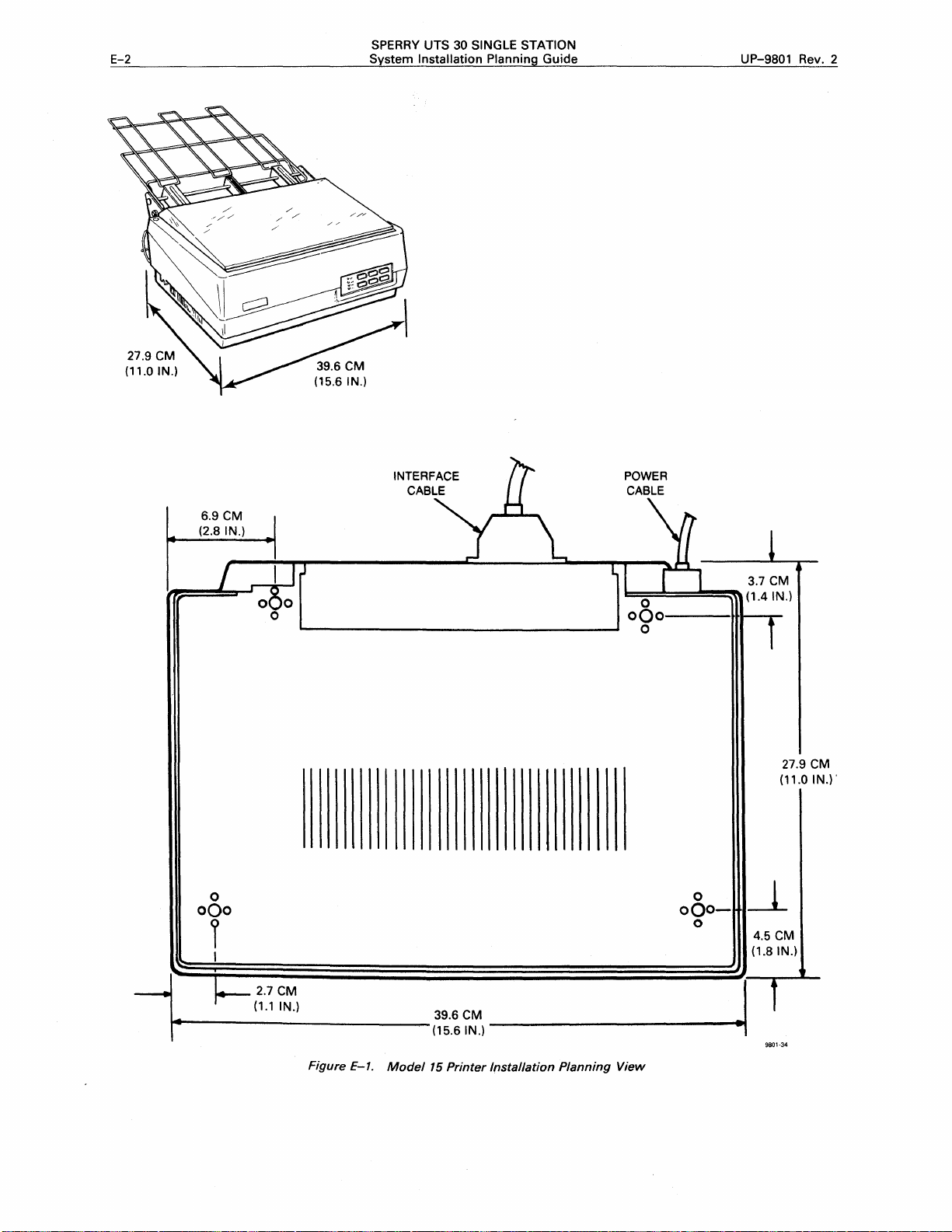
E-2
SPERRY UTS 30 SINGLE STATION
System Installation Planning
Guide
UP-9801 Rev. 2
6.9 CM
(2.8 IN.)
0
oQo
I
INTERFACE
CABLE
--~----------~--------------~----'
POWER
CABLE
1:::::
;:::::=:!::::::::::!~~
0
oQo---··•---.~
0
oOo-
0
3.7
( 1 .4 IN.)
_j_
4.5 CM
(1.8 IN.)
CM
27.9 CM
(11.0 IN.).
-•
______
,-
1
2.7CM
(1.1
IN.)
Figure E-1.
Model
39.6CM
(15.6
IN.)-------------•~
15
Printer
Installation
Planning
I
9801-34
View

UP-9801 Rev. 2
SPERRY
System Installation Planning Guide
UTS 30 SINGLE STATION
F-1
PHYSICAL INFORMATION
Dimensions
Width
Depth 46.0 cm
Height
With
cut-sheet
feeder
65.5 cm (25.8 in.)
23.9 cm (9.4 in.)
57.7
cm
ENVIRONMENTAL INFORMATION
Maximum
Heat
Dissipation
Appendix
(18.1
in.)
(22.5 in.)
F.
Model 35 Printer
Summary
Weight
Recommended
Front
Rear 38.1
Sides 15.2
Top
Temperature
Range
Clearances
As
required
cm
cm
38.1
cm
32.0
kg
by
( 15 in.)
(6 in.)
(15 in.)
Data
(70 lb)
operator
142 kcal/hr (165
258 kcal/hr (300
Air
Circulation
Forced
air
watts)
watts)
(fan)
ELECTRICAL INFORMATION
Power
Recommended
Requirements
0.22 kVA
Domestic:
International:
(Approximately
220
User
Circuits
60 Hz, 120 Vac,
50 Hz, 100 Vac,
50 Hz, 220/240 Vac,
watts)
single
single
phase, 2
phase, 2
single
wire
wire
phase, 2
Operating:
Shipping
To 72
To 6
Relative
Operating:
Shipping
To 6
and
ground
and
ground,
wire
and
10°
and
hours:
months:
Humidity
20%
and
months:
or
ground
to
34° C (50°
Storage:
-40°
(-40°
-22°
(-8°
Range
to
85%
Storage:
1%
to
to
to
to
to
95%
to
62° C
144°
47° C
117°
93°F)
F)
F)

F-2
SPERRY UTS 30 SINGLE STATION
System Installation Planning
Guide
UP-9801 Rev. 2
46.0
(18.1
CM
IN.)
5.0
CM
(2.0 IN.)
I
®
~
I
_.,.._---1~
Figure F-1.
60.5
CM
(23.8 IN.)
65.5
CM
(25.8 IN.)
CM
51.0
(20.0 IN.)
Model
35 Printer Installation Planning View
I
1
10.2
CM
(4.0 IN.)
31.2
(12.1
CM
IN.)
9801-35

UP-9801 Rev. 2
SPERRY UTS 30 SINGLE STATION
System Installation Planning Guide G-1
Appendix G.
PHYSICAL INFORMATION
Dimensions
Width
Depth
Height
Weight
ENVIRONMENTAL INFORMATION
Maximum
10.3 kcal/hr (12
Heat
Dissipation
watts)
20.3 cm (8.0 in.)
31.1
cm (12.3 in.)
9.2 cm (3.6 in.)
2.5
kg
(5.5 lb)
8610 Direct Connection
Module
Recommended
Top
Bottom
Rear
Temperature
5°
to
43° C (40°
Summary
Clearances
1.0
cm
(0.38 in.)
1.0
cm
(0.38 in.)
10.2
cm
Range
to
110°
F)
Data
(4.0 in.)
Air
Circulation
Natural
convection
ELECTRICAL INFORMATION
Power
NOTE: A
Recommended
Requirements
0.012 kVA
common
Domestic:
International:
User
power
Circuits
60
Hz,
50
or
60
50
or
60
source
120 Vac, single phase, 2
Hz,
Hz,
Relative
5%
to
and
power
100/120 Vac, single phase, 2
220/240 Vac, single phase, 2
ground
wire
are
not
and
Humidity
95%
required
ground
wire
and
wire
and
Range
between
ground,
ground
DCMs.
or

G-2
SPERRY
UTS
30
SINGLE STATION
System Installation Planning Guide
UP-9801 Rev. 2
31.1 CM
(12.3
IN.I
I
4.1 CM
(1.6
IN.I
POWER
CABl,.E
I '
\..
_____
[§]
_;
10000001 I 000000001
looooool
Jl
I
L----...1
I
000000001
J2
I I I
L
_______
[§]
J
Figure G-1. 8610 Direct Connection
4.1
CM
(1.6
IN.I
14----------f~g
Module
Installation Planning View
I~~}~-------•
I
9801·36

UP-9801 Rev. 2
SPERRY
System Installation Planning Guide
UTS 30 SINGLE STATION
H-1
Appendix H. 8609 Terminal Multiplexer
PHYSICAL INFORMATION
Dimensions
Width
Depth
Height
Weight
41.9
cm
(16.5 in.)
cm
36.8
20.3
8.6 kg (19.0
(14.5 in.)
cm
(8.0 in.)
ENVIRONMENTAL INFORMATION
Maximum
Minimum
Maximum
Heat
Dissipation
configuration
43.0 kcal/hr (50
configuration
64.5 kcal/hr (75
watts)
watts)
lb)
Summary
Recommended
5
cm
(2 in.)
Temperature
5°
to
43° C (40°
Relative
5%
to
on
Range
Humidity
95%
Data
Clearances
all
sides
to
110°
F)
Range
Air
Circulation
Natural
convection
ELECTRICAL INFORMATION
Power
Recommended
Requirements
0.075 kV A (75
Domestic:
International:
watts)
User
Circuits
60 Hz, 120 Vac,
50
or
60 Hz, 220/240 Vac,
single
phase, 2
single
wire
and
phase, 2
ground,
wire
and
or
ground

H-2
SPERRY UTS 30 SINGLE STATION
System Installation Planning Guide
41.9
CM
06.S
IN.I
--,
: POWER
I
CABLE
I
-
_,
UP-9801 Rev. 2
FRONT
Figure H-1. 8609 Terminal
12.2
IN.I
u~J
i.-------------(~~--~~~,---------.t•
Multiplexer
Installation Planning View
I
9355-16

UP-9801 Rev. 2
SPERRY
System Installation
UTS 30 SINGLE STATION
Planning Guide
1-1
Appendix
PHYSICAL INFORMATION
Dimensions
Width
Depth
Height
Weight
ENVIRONMENTAL INFORMATION
Maximum
Maximum
Air
Circulation
Forced
Heat
Dissipation
configuration
51.4 kcal/hr (60
air
(fan)
watts)
42.6 cm (16.8 in.)
44.6
cm
16.5
cm
kg
(20 lb)
9
(17.6 in.)
(6.5 in.)
8613 Signal Distribution
I.
Module
Recommended
10.2
cm
Temperature
Operating:
Shipping
To 72
To 6
Summary
Clearances
(4.0 in.)
and
hours:
months:
Range
10°
to
Storage:
on
34° C (50°
all sides
-42°
to
(-40°
to
-22°
to
(-8°
to
to
62° C
144°
47°C
117°
Data
93°
F)
F)
F)
ELECTRICAL INFORMATION
Power
Recommended
Requirements
0.06 kVA (60
Domestic:
International:
watts)
User
Circuits
60 Hz, 120 Vac,
50
or
60
Hz,
50
or
60
Hz,
single
100/120 Vac,
200/240 Vac,
phase, 2
single
single
Relative
Operating:
Shipping
wire
and
phase, 2
phase, 2
Humidity
To 6
ground
wire
wire
5%
and
Storage:
months:
and
ground,
and
ground
Range
to
95%
1%
to
95%
or

1-2
SPERRY
System Installation Planning
UTS 30 SINGLE STATION
Guide
UP-9801 Rev. 2
3.2 CM
r--
(1.3
~ ·~
IN.)
0
G
__________
42.6
CM
(16.8 IN.)
______
4.5 CM
(1.8 IN.)
[!)-
G-
I
-+--1
___
_t_
44.6 CM
(17.6 IN.
:--.-
~
..._
..
t
6.9
CM
(2.8 IN.)
9801·38
Figure
1-1.
8613
Signal
Distribution
Module
Installation Planning View
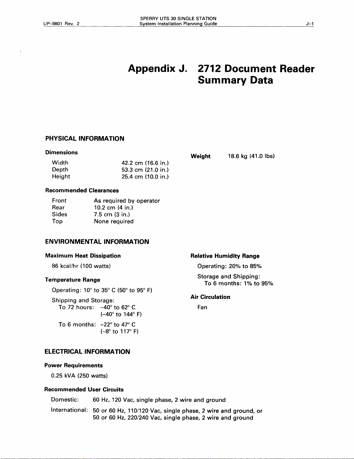
UP-9801 Rev. 2
SPERRY
System Installation Planning Guide
UTS 30 SINGLE STATION
J-1
PHYSICAL INFORMATION
Dimensions
Width
Depth
Height
Recommended
Front
Rear 10.2
Sides 7.5
Top
Clearances
As
required
cm
None
42.2
53.3
25.4
cm
(4 in.)
(3 in.}
required
Appendix J.
cm
(16.6 in.)
cm
(21.0 in.)
cm
(10.0 in.)
by
operator
2712 Document Reader
Summary
Weight
18.6 kg (41.0 lbs}
Data
ENVIRONMENTAL INFORMATION
Maximum
86 kcal/hr (100
Temperature
Operating:
Shipping
To 72
To 6
Heat
Dissipation
Range
10°
and
Storage:
hours:
months:
watts)
to
35° C (50°
-40°
(-40°
-22°
(-8°
to
to
to
62° C
to
47° C
117°
to
144°
95°
F)
F}
ELECTRICAL INFORMATION
Power
Recommended
Requirements
0.25 kVA (250
Domestic:
watts)
User
Circuits
60 Hz, 120 Vac,
single
F}
phase, 2
wire
Relative
Operating:
Storage
To 6
Air
Circulation
Fan
and
ground
Humidity
20%
and
Shipping:
months:
Range
to
85%
1%
to
95%
International:
50
50
or
or
60
60
Hz,
110/120 Vac,
Hz,
220/240 Vac,
single
single
phase, 2
phase, 2
wire
wire
and
and
ground,
ground
or

J-2
SPERRY
System Installation Planning
UTS 30 SINGLE STATION
Guide
2.0CM
(0.8 IN.)
UP-9801 Rev. 2
r
0
0
0
c
"
I
I
c
2.0
(0.8 IN
11.2 c
(4.4 I
53.3
(21.0 IN.)
M
.)
M
N.)
CM
_j_
"'
J
...
T
:...
,..
Figure J-1. 2712
3.8CM
(1.5 IN.)
42.2 CM
(16.6
Document
3.8
CM
l
(1.5 IN.)
IN.)
Reader Installation Planning
I
..I
--
-
~
9801·39
View

UP-9801 Rev. 2
SPERRY
System Installation Planning Guide
UTS 30 SINGLE STATION
K-1
PHYSICAL INFORMATION
Dimensions
54.6
cm
cm
cm
(21.5 in)
(18.5 in)
(21.5 in)
Width
Depth
Without
With
Height
Weight
cable
cable
cover
cover
47.0
54.6
16.0 cm (6.3 in)
24.9 kg (55
ENVIRONMENTAL INFORMATION
Appendix
Recommended
Front
Rear
Without
With
Sides
lbs)
Power
K.
Cord
DOPS/20 Processor
Summary
Clearances
cable
cover
cable
cover
Length
Data
As
required
operator
10.2
cm
cm
2.5
10.2
cm
2 m (6.6
by
(4.0 in)
(1.0 in)
(4.0 in)
ft)
Maximum
189 kcal/hr (220
Temperature
Operating:
Shipping
Heat
and
Up
to
72
Up
to 6 months:
Dissipation
watts)
Range
10°
to
Storage:
hours:
34° C (50°
-40°
to
(-40°
to
-22°
to
(-8°
to
ELECTRICAL INFORMATION
Power
Recommended
Requirements
0.26
kVA
(26
Domestic:
International:
watts)
User
Circuits
60 Hz, 120 Vac,
50
or
60 Hz, 110/120 Vac,
50
or
60 Hz, 220/240 Vac,
to
62° C
144° F)
47° C
117°
single
93°
F)
F)
phase, 2
single
single
wire
and
phase, 2
phase, 2
Relative
Operating:
Storage
Limited
diskette
Air
Circulation
Fan
ground
wire
and
wire
and
Humidity
10%
and
Shipping:
to
80% because
ground,
ground
Range
to
80%
or
of
integral

K-2
SPERRY UTS 30 SINGLE STATION
System Installation Planning Guide
UP-9801 Rev. 2
•
l_
1"'1
--------------
4
I
"I.
19.1
CM I J
7
5
52.6 CM
(21.5 IN.)
Figure K-1. DOPS/20 Processor Installation Planning View
__
:~~~~~~---(
_·
_1_N_.)_-_
47.0
CM
(18.5 I
N.)
::r1
I
'
--------~·~
...
9801-40

UP-9801
Rev.
2
SPERRY
System Installation Planning Guide
UTS
30
SINGLE STATION
l-1
Appendix
PHYSICAL INFORMATION
Dimensions
Width
Height
Depth
Weight
Recommended
Front
Rear
Sides
Top
Clearances
As
required
As
required
None
required
None
required
42.6
15.9
44.6
12.2
for
for
L.
cm
(16.8 in.)
cm
( 6.25 in.)
cm
(17.6 in.)
kg
(27 lb)
operating
cabling
8441
Mass
Summary
Storage
Data
Subsystem
Power
Cord
2 m (6.6
Length
ft)
ENVIRONMENTAL INFORMATION
Maximum
97 kcal/hr (113
Air
Circulation
Forced
Temperature
10°
Relative
20%
Heat
air
to
34° C (50°
Humidity
to
80%
Dissipation
watts)
(fan)
Range
to
Range
93°
F)
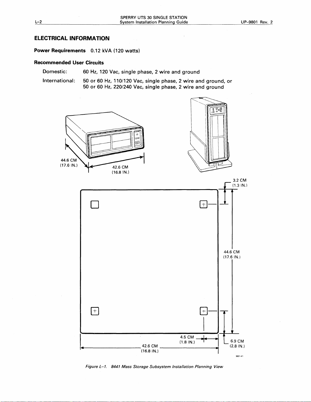
L-2
ELECTRICAL INFORMATION
SPERRY UTS 30 SINGLE STATION
System
Installation Planning
Guide
UP-9801 Rev. 2
Power Requirements 0.12 kVA ( 120
Recommended User Circuits
Domestic:
International:
60
50
50
Hz,
or
or
60
60
120 Vac,
Hz,
110/120 Vac,
Hz,
220/240 Vac,
D
watts)
single
phase, 2
single
single
wire
and
phase, 2
phase, 2
ground
wire
and
wire
and
ground,
ground
@-
1
•
_t_
or
--
3.2 CM
(1.3
•
IN.)
G
----------
Figure
L-1. 8441
Mass
42.6 CM
(16.8 IN.)
Storage
_______
Subsystem
4.5 CM
(1.8 IN.)
Installation
44.6 CM
(17.6
I
1-.
tr
j
L__
.,..
View
(2.8
G-
--+--1
___
Planning
•
6.9
IN.
CM
IN.)
9801-41

Your
Name
READER'S COMMENT SHEET
comments
of
on
this manual
manual:------------------------------------
will
help
us
improve
it.
Please
fill
in
the requested
information.
Manual number:
Name
of
your
company:-------------------------------~
Address
What
Your
With
How
Please
Add
of
company:---------------------------------~
is
your
position?---------------------------------
level
of
experience: Professional
what
system
do
you
use
As a reference source
As a classroom
rate this manual
As a reference source:
As a
text:
For
other
uses:
your
specific comments. Give
UP-__
is
the equipment
this manual?
D
text
O
revision number
used?--------------------------
Good0
Good0
Good0
page
___
___
As
As D
Adequate 0
Adequate 0
Adequate D
and paragraph references where appropriate.
, including update
Knowledgeable
a self-instructional
___
text
Not
adequate 0
Not
adequate 0
Not
adequate 0
numbers-----
Novice----
D
Thank
you
for
your
cooperation.

I
I
PLEASE
SEND
US
I
We feel
that
this
I
usable
with
the
carefully
manual
possible.
manual,
reviewed
manual
please
by
I
I
I
I
I
I
FOLD
1-----------------------
1
YOUR
is
Your
fill
the
persons
COMMENTS!
an essential
comments
in
the
other
responsible
part
will
side
of
help
of
for
our
equipment.
us achieve
this
form
writing
and
and
We
want
this
goal.
mail
the
publishing
to
When
form
this
be
sure
you
have
to
us.
manual.
it
is
become
Your
the
best,
reply
most
familiar
will
Qe
I
Bus
IN
POSTAGE
Es
s RE p
WILL
BE
Ly
PAID
MA
BY
IL
NO
POSTAGE
~~Si='E~V
322 NORTH 2200 WEST
SALT
ATTN: MANAGER,
I
-----------------------------
FOLD
NOTE:
Requests for copies
for assistance in getting the most use out
be
directed
LAKE CITY, UTAH 84116
GSD
PUBLICATIONS
of
this manual and other Sperry publications and
to
your local Sperry representative.
of
your Sperry equipment should
STAMP
NECESSARY
IF
MAILED
IN
THE
UNITED
STATES
 Loading...