

08/04 Form # 409
OPERATING INSTRUCTIONS
V.O. mA MULTIMETERS
PLEASE READ THESE
OPERATING INSTRUCTIONS
CAREFULLY
MISUSE AND OR ABUSE OF
THESE INSTRUMENTS CANNOT
BE PREVENTED BY ANY
PRINTED WORD AND MAY
CAUSE INJURY AND OR
EQUIPMENT DAMAGE PLEASE
FOLLOW ALL THESE
INSTRUCTIONS AND
MEASUREMENT PROCEDURES
FAITHFULLY AND ADHERE TO
ALL STANDARD INDUSTRY
SAFETY RULES AND
PRACTICES.
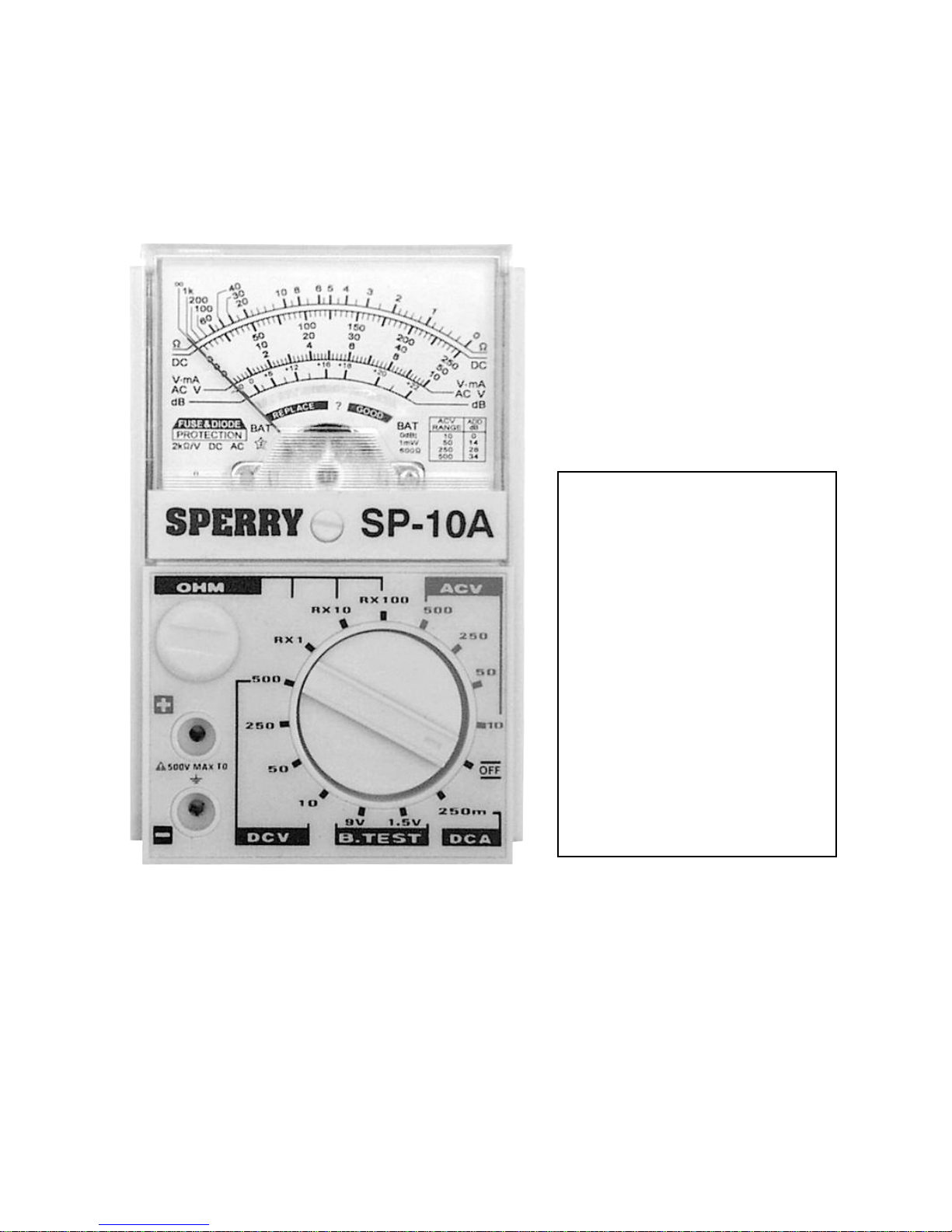
MODEL
SP-10A
PRINTED IN CHINA
MADE IN CHINA
A.W. SPERRY INSTRUMENTS INC.
Byram Laboratories, Inc. 1 Columbia Rd, Branchburg, NJ 08876
Phone: 800-766-1212 or 908-252-0852
Fax: 908-252-0822
www.byramlabs.com

SPECIFICATIONS
SP–10A
SENSITIVITY 2 kΩ/V AC & DC
AC V 10/50/250/500
DC V 10/50/250/500
DC MA 250
OHMS FULL RANGE 1K/10K/100KΩ
OHMS MID SCALE 5/50 /500Ω
dB -20 T0 +56
SPECIAL FEATURES SEPARATE 1.5V TO 9V
BATTERY CHECK RANGES
ACCURACY DC ± 3% FS - OHMS ± 3% OF ARC
INDOOR USE
TEMPERATURE 5
0
C TO 400C
MAXIMUM RELATIVE HUMIDITY 80% @ 31
0
C
MINIMUM 50% @40
0
C
BATTERY COMMERCIAL ELECTRIC ™ PART # B - 1, TYPE AA, 1.5VDC
FUSE COMMERCIAL ELECTRIC ™ PART # F - 7. MINIATURE GLASS
TYPE, 5x20MM1/2 AMP, 250VAC, FF
DIMENSIONS 4”H x 2.9”W x 15/16”D (100H x 63W x 34DMM)
WEIGHT 3.6OZ. (102GMS)
TEST LEADS TL-34
ONE YEAR LIMITED WARRANTY
A.W Sperry Instruments Inc. warrants that this A.W Sperry Instruments Inc. has been carefully tested,
inspected and warranted for one (1) year from the date of purchase by the original end user, provided the
instrument has not been misused, damaged due to negligence, neglect or unauthorized repair, abused or
used contrary to the operating instructions.
Instruments and proof of purchase in the form of a legible copy or original of the sales receipt clearly
identifying the distributor, model number and date of purchase must be returned to A.W Sperry
Instruments Inc., Attention: Customer Service Center, 245 Marcus Boulevard, Hauppauge, NY 11788
postage prepaid for examination and verification of manufacturing defect under warranty. A.W Sperry
Instruments, Inc. shall be the sole judge of such defect. The liability of A.W Sperry Instruments, Inc. shall
be limited to the repair or replacement at its sole option of any defective product.
THIS WARRANTY AND THE OBLIGATIONS AND LIABILITIES OF SELLER THEREUNDER ARE
EXCLUSIVWE AND IN LIEU OF AND BUYERS HEREBY WAIVES ALL OTHER REMEDIES, EXPRESS
WARRANTIES, GUARANTEES OR LIABILITIES OF AND FOR INCIDENTAL OR CONSEQUENTIAL
DAMAGES OR WHETHER OR NOT OCCASIONED BY SELLER’S NEGLIGENCE. THIS WARRANTY
SHALL NOT BE EXTENDED, ALTERED OR VARIED EXCEPT BY A WRITTEN INSTRUMENT SIGNED
BY SELLER AND BUYER. SOME STATES ALLOW LIMITATIONS ON HOW LONG AND IMPLIED
WARRANTY LASTS, SO THE ABOVE LIMITATION ON HOW LONG AN IMPLIED WARRANTY LASTS,
SO THE ABOVE LIMITATIONS MAY NOT APPLY TO YOU. THIS WARRANTY GIVES YOU SPECIFIED
LEGAL RIGHTS AND YOU MAY ALSO HAVE OTHER RIGHTS WHICH VARY STATE TO STATE.
2
OPERATING
ENVIRONMENT
Instrument complies with insulation category (over voltage category II)
Pollution degree 2 in accordance with IEC-644
This equipment has been evaluated to INSTALLATION CATEGORY (OVERVOLTAGE
CATEGORY II)
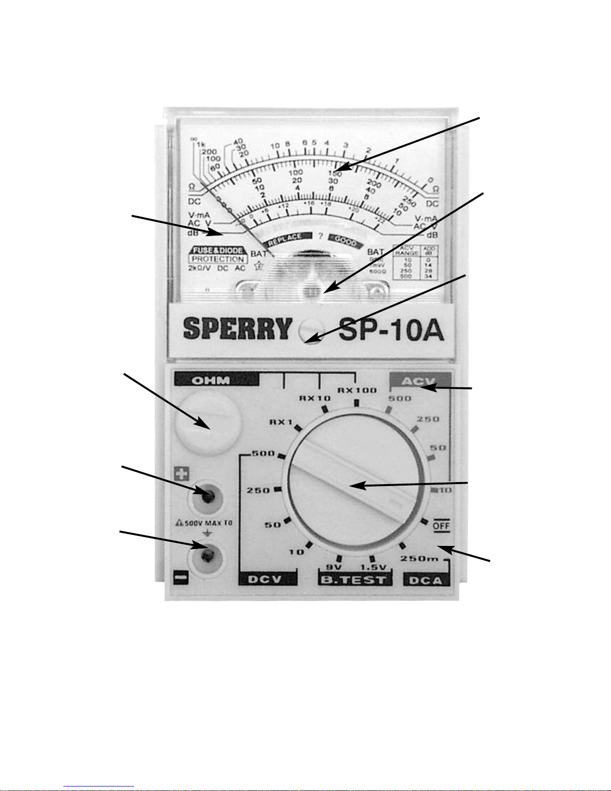
POINTER
ZERO
OHM
ADJUST
+ JACK
- JACK
RANGE
DECAL
RANGE
SWITCH
CASE
SCALE
PLATE
COVER
ZERO
ADJUST
FIG. 1
3

Always inspect your meter, test leads and accessories for any signs of damage or abnormality
before every use. If any abnormal condition exist: e.g. broken test lead, cracked case etc., do
not attempt to take any measurements. Return for repair to 245 Marcus Boulevard,
Hauppauge, NY 11788
DOUBLE INSULATION
WARNING:TO AVOID ELECTRIC SHOCK, DISCONNECT
MEASURING TERMINALS BEFORE REMOVING BACK COVER.
CAUTION:FOR CONTINUED PROTECTION AGAINST FIRE, REPLACE
ONLY WITH FUSE OF THE SPECIFIED VOLTAGE, CURRENT, AND RUPTURE
SPEED RATINGS.
TO PLACE MINI-METER™ IN OPERATION:
A. BATTERY
1. A battery is furnished with each instrument. Remove back case and make certain it is in
place, in proper polarity + and – is molded in well under battery.
2. For replacement, use "AA" battery.
3. If instrument is not in service for a long time, remove battery and store separately.
4. To avoid battery drain, always set Range knob at OFF position.
B. FUSE
1. A fuse is furnished with each instrument, installed in a fuse holder. Check to make sure
the fuse is securely in its clips at the time you check the battery.
2. For replacement, use A.W. Sperry Instruments Inc. Part # F-7 fuse.
CAUTION: DO NOTshort fuse out of the circuit, or use a fuse with a higher rating
than Ω amp., or alter circuit to eliminate fuse. These actions negate the safety purpose of the
Fuse, can cause damage to the instrument and or equipment being measured and or injury to
the user.
C. ZERO ADJUSTMENT
1. Before use and for greatest accuracy, make certain that the pointer is set exactly on the
Zero Line, at the extreme left of the arc.
2. If not on zero, rotate the Zero Adjuster Screw, at middle bottom of window, until pointer
is directly over the line zero.
3. It is good practice to check the zero adjustment daily, since changes in atmospheric
conditions can cause it to drift in position.
D. TESTLEADS
1. One (1) pair consisting of a Red Lead and a Black Lead, is furnished with
each instrument.
2. The short insulated probe tips fit into the two receptacles on the front cover.
3. The long insulated prod handles are used to make contact with the circuit
being measured.
4
!
!

Before taking any measurements, ALWAYS REMEMBER TO
CAREFULLY CHECK THE FUNCTION DESIRED, THE POSITION OF THE ROTARY
SWITCH AND THE RANGE TO BE USED. START WITH THE HIGHEST RANGE AND WORK
DOWN TO LOWER RANGES UNTIL POINTER READS IN UPPER HALF OF SCALE.
MEASUREMENT PROCEDURE
To minimize possibility of damage to the instrument and to obtain a long trouble-free field
life, the following procedure is recommended.
E. ACCURACY
1. For best accuracy, the pointer should read in the upper half of the scale, preferably in
the fourth quadrant of the arc, where accuracy is best.
F. SWITCH POSITION
1. Prior to use, SET THE SWITCH TO THE HIGHEST RANGE OF THE FUNCTION TO
BE MEASURED.
Work down to lower successive ranges of this function until the pointer reads in the
upper half of the scale.
.
For example, in preparing to read AC volts, set the switch to highest range then take
measurement. Work the switch down to lower ranges of AC volts until the pointer reads in
the upper half of the arc.
.
In this fashion, the instrument is protected against overloads where circuit values are
not known.
2. When finished with measurements of one function, remove Test Leads COMPLETELY
from the circuit, if another different function is to be measured, FIRST set switch to the
highest range of the new function, THEN take measurements.
HOW TO READ AC VOLTS
1. Connect Red short probe in + Jack, Black in – Jack. Read all AC Volt Ranges on the
third arc down.
2. Voltage measurements are taken by connecting the instrument in parallel with thecircuit
being checked. The long insulated prod handles are used to make contact with the circuit.
NOTE: For maximum safety, do NOT hold the Mini-Meter in your hand on the two highest
AC Volt ranges. (250 & 500V AC)
HOW TO READ DC VOLTS
1. Connect Red short probe into + Jack, Black in - Jack.
2. Read all DC volt range on the second arc down.
3. Voltage measurements are taken by connecting the instrument in parallel with the circuit
being checked. The long insulated prod handles are used to make contact with the circuit.
NOTE: For maximum safety do NOT hold the Mini-Meter in your hand on the two
highest DC Volt ranges. ( 250 & 500 VDC)
5

6
HOW TO READ DC MILLAMPS
1. Connect Red short Probe in + Jack, Black in - Jack.
2. Read all DC Milliamp Ranges on the second arc down.
3. For current measurements, open the circuit and connect the instrument in series with
the circuit being measured.
CAUTION
Make certain that the circuit to be measured is completely De-Energized
(
DEAD)with NO
live voltage in the circuit whatsoever.
Before taking any resistance measurement, disconnect line voltage fro circuit being
measured, or feeder voltage from any component being checked.
HOW TO READ OHMS
1. Set Range knob selector to suitable OHM Range.
2. Connect Red short Probe in + Jack, Black in – Jack
3. Short the Long Prod handles and adjust the Zero Ohm adjust pot (see Fig. 1) until the
pointer is directly over the Zero position on the Ohm Range (at extreme right).
Note: If Ohm Zero position cannot be adjusted, change the battery
4. Touch the long prod handles across the circuit, or component to be measured and
read on the Ohm arc. (Top Arc).
IMPORTANT - PLEASE READ CAREFULLY
Impressing live voltage across the Ohm circuit by mis-use or abuse may result in injury to
the operator and/or damage to the instrument and the equipment being checked. The extent
of the damage will depend on the volts and amps going at time of measurement.
CAUTION
Make certain that the circuit to be measured is completely De-Energized
(
DEAD)with NO
live voltage in the circuit whatsoever.
Before taking any resistance measurement, disconnect line voltage for circuit being
measured, or feeder voltage from any component being checked.
HOW TO USE THE BATTERY CHECK RANGES
1. The SP-10A comes with two separate battery check ranges that enable you to test either
1.5VDC or 9VDC batteries
2. Connect Red short Probe to + Jack, Black to - Jack.
3. Set the range selector switch to the 1.5V battery test range
4. Connect the test leads to the 1.5VDC battery under test. A good 1.5VDC battery will
read in the green portion of the Arc.
5. To check 9V batteries follow the above procedures with the range selector switch set
to 9V.
6. The “REPLACE” section of the scale plate shows that the battery may be starting
to decay.
Note: May not read various 1.5VDC button cell batteries.

HOW TO READ DECIBLES (DB)
Note:
In order to eliminate the DC components I the circuit, connect a O. 1 microFarad
Capacitor, or larger, in series with one of the Test Leads.
1. The db arc is 4th down, in Red.
2. Connect Red Short probe to + Jack, Black to – Jack.
3. Set switch knob selector to 10V AC Range, read direct on upper db arc, -20 to 22.
4. For measurement above the basic db range, set switch to the next highest AC Voltage
range and add db as shown in the table on the scale plate.
ACCESSORIES
Battery-Replace with
"AA"
Battery.
Fuse-Replace with A.W. Sperry Instruments Inc. Part # F-7 Fuse.
Test Leads-Replace with A.W. Sperry Instruments Inc. Part # TL-34 Test Leads.
IN STOCK- AT YOUR LOCAL WHOLESALER
GENERAL USAGE & MAINTENANCE
THINK SAFETY - ACT SAFELY.
DO NOT SOLDER WIRE ACROSS THE FUSE CLIPS, OR RE-INSERT BURNED
OUT FUSE WITH METAL FOIL ENCLOSING IT OR BYPASS THE SAFETY FUSE IN
ANY WAY.
DO NOT exceed the published maximum for each function.
DO NOT polish the window or attempt to clean it with cleaning fluid, kerosene or
gasoline - damage will result.
When volt measurements are completed, FIRST remove the Test Leads from circuit
being checked, AND THEN remove Test Leads from instrument jacks.
Remove grease and grime with a clean dry cloth.
When instrument is NOT in use, set Switch knob to “OFF”.
When measuring OHMS, MAKE SURE the circuit being checked is DEAD, completely
DE-ENERGIZED.
Avoid severe continuous mechanical shock or vibration, extreme temperature or very
strong magnetic fields.
7

RETURN FOR REPAIRS
Before returning your analog multimeter for repair be sure to check that the failure to operate
is not due to the following:
1. Weak Battery
2. Open Fuse
3. Open, loose or intermittent test leads.
If these conditions do not exist and the instrument fails to operate properly, return the
instrument and accessories prepaid:
State in writing what is wrong with the instrument. All warranty repairs must include proof of
purchase in the form of a legible or original copy of the sales receipt, clearly identifying the
distributor, model number and date of purchase and must have a warranty card on file. See
warranty statement on page 2 for full warranty disclosure. Repair estimate will be furnished if
requested for out of warranty instruments. Be sure to include all accessories, which may be
related to the problem and a note describing the malfunction you observed.
8
A.W. SPERRY INSTRUMENTS INC.
Byram Laboratories, Inc. 1 Columbia Road, Branchburg, NJ 08876
Phone: 800-766-1212 or 908-252-0852
Fax: 908-252-0822
www.byramlabs.com
 Loading...