


Users Manual
Read this manual thoroughly before use
Digital Multimeter


SAFETY INFORMATION
This meter has been designed according to IEC 61010 concerning
electronic measuring instruments with a measurement category
( CAT III 600V ) and pollution degree 2.
Warning
WARRANTY
This instrument is warranted to be free from defects in material and
workmanship for a period of one year. Any instrument found
defective within one year from the delivery date and returned to the
factory with transportation charges prepaid, will be repaired,
adjusted, or replaced at no charge to the original purchaser. This
warranty does not cover expandable items such as battery or fuse. If
the defect has been caused by a misuse or abnormal operating
condition, the repair will be billed at a nominal cost.
To avoid possible electric shock or personal injury, follow these
guidelines:
Do not use the meter if it is damaged. Before you use the meter,
inspect the case. Pay particular attention to the insulation
surrounding the connectors.
Inspect the test leads for damaged insulation or exposed metal.
Check the test leads for continuity. Replace damaged test leads
before you use the meter.
1

Do not use the meter if it operates abnormally. Protection may be
impaired. When in doubt, have the meter serviced.
Do not operate the meter around explosive gas, vapor, or dust.
Do not apply more than the rated voltage, as marked on the
meter, between terminals or between any terminal and earth
ground.
Before use, verify the meter's operation by measuring a known
voltage.
When measuring current, turn off circuit power before connecting
the meter in the circuit. Remember to place the meter in series
with the circuit.
When servicing the meter, use only specified replacement parts.
Use caution when working with voltage above 30V ac rms, 42V
peak, or 60V dc. Such voltages pose a shock hazard.
When using the probes, keep your fingers behind the finger
guards on the probes.
When making connections, connect the common test lead before
you connect the live test lead. When you disconnect test leads,
disconnect the live test lead first.
Remove the test leads from the meter before you open the
battery cover or the case.
Do not operate the meter with the battery cover or portions of the
case removed or loosened.
To avoid false readings, which could lead to possible electric
shock or personal injury, replace the batteries as soon as the low
battery indicator ( ) appears.
2

3
Warning: Any changes or modifications to this unit not expressly
approved by the party responsible for compliance could void the
user's authority to operate the equipment.
This device complies with part 15 of the FCC Rules. Operation is
subject to the following two conditions: (1) This device may not
cause harmful interference, and (2) this device must accept any
interference received, including interference that may cause
undesired operation.
NOTE: This equipment has been tested and found to comply
with the limits for a Class B digital device, pursuant to part 15 of
the FCC Rules. These limits are designed to provide reasonable
protection against harmful interference in a residential
installation. This equipment generates, uses and can radiate
radio frequency energy and, if not installed and used in
accordance with the instructions, may cause harmful
interference to radio communications. However, there is no
guarantee that interference will not occur in a particular
installation. If this equipment does cause harmful interference to
radio or television reception, which can be determined by turning
the equipment off and on, the user is encouraged to try to correct
the interference by one or more of the following measures:
— Reorient or relocate the receiving antenna.
— Increase the separation between the equipment and receiver.
— Connect the equipment into an outlet on a circuit different
from that to which the receiver is connected.
— Consult the dealer or an experienced radio/TV technician for
help.

To avoid electric shock, do not touch any conductor with hand or
skin; and do not ground yourself while using this meter.
When in Data Hold mode, the symbol " " is displayed. Caution
must be used because hazardous voltage may be present.
Do not use the meter in a manner not specified by the
manufacturer or the safety features provided by the meter may
be impaired.
Adhere to local and national safety codes. Individual protective
equipment must be used to prevent shock and arc blast injury
where hazardous live conductors are exposed.
Do not use the meter if the meter, a test lead or your hand is wet.
For measurements on main or within Measurement Category
III/IV circuits, the attached test probes must be set in
Measurement Category III/IV mode; otherwise electric shock
may occur!
Remaining endangerment:
When an input terminal is connected to dangerous live potential
it is to be noted that this potential can occur at all other terminals.
CATIII - Measurement Category III is for measurements
performed in the building installation. Examples are
measurements on distribution boards, circuit breakers, wiring,
including cables, bus-bars, junction boxes, switches, socket-outlets
in the fixed installation, and equipment for industrial use and
some other equipment, for example, stationary motors with
permanent connection to the fixed installation.
Do not use the meter for measurements within Measurement
Category IV.
4

Alternating Current
Direct Current
DC or AC
Caution, risk of danger, refer to the operating manual before
use.
Caution, risk of electric shock.
Earth ground
Fuse
Conforms to European Union directives
The equipment is protected throughout by double insulation or
reinforced insulation.
Symbols
5
Caution
To avoid possible damage to the meter or to the equipment
under test, follow these guidelines:
Disconnect circuit power and discharge all capacitors thoroughly
before testing resistance, diode, continuity, temperature or
capacitance.
Use the proper terminals and function for your measurements.
Before measuring current, check the meter's fuse and turn off
power to the circuit before connecting the meter to the circuit.
Before turning the rotary switch to change function, remove the
test leads from the circuit under test.

Figure 1
INTRODUCTION
This instrument is a compact 3 3/4 digits autorange true-rms digital
multimeter designed to measure DC and AC voltage, DC and AC
current, resistance, continuity, diode, capacitance, frequency, duty
cycle and temperature. It features data hold, relative measurement,
MIN MAX recording mode, backlight, non-contact ac voltage
detection, Bluetooth communication, data recording, and etc. It is easy
to operate and is a useful test tool.
6
FRONT PANEL
1
2
3
7
8
9
4 5 6

1. Display
3 3/4 digits LCD, 4000 counts.
2. " SELECT " Button
This " SELECT " button can be used to switch the meter
between:
DC voltage and AC voltage measurement functions.
DC current and AC current measurement functions.
Resistance, diode and continuity test functions.
Frequency and duty cycle measurement functions.
Celsius temperature and Fahrenheit temperature measurement
functions.
In addition, you can hold down this " SELECT " button for about
2 secs to enable or disable the Bluetooth communication
function. When the Bluetooth communication function is enabled,
the automatic power-off function is disabled automatically.
3. "
RELATIVE
" Button
This "
RELATIVE
" button can be used to enter or exit Relative
mode. In addition, you can hold down this button for about 2 secs
to start or stop recording readings in the memory of the meter.
When the recording starts, the meter's automatic power-off
function is disabled automatically.
For detailed information about the recording function, please read
the relevant section of the operation instruction of the
communication application.
7

8
4. " 10A " Terminal
Input terminal for current measurements.
5. " COM " Terminal
Common ( return ) terminal for voltage, current, resistance,
diode, continuity, frequency, duty cycle, capacitance and
temperature measurements.
6. " INPUT " Terminal
Input terminal for voltage, resistance, diode, continuity, duty
cycle, frequency, capacitance and temperature measurements.
7. Rotary Switch
Used to select desired function as well as to turn on or off the
meter.
To save battery power, set this rotary switch in the " OFF "
position to turn off the meter when the meter is not in use.
8. " MAX/MIN " Button
Used to enter or exit MIN MAX recording mode.
The meter's automatic power-off function will be disabled
automatically when the meter enters MIN MAX recording mode.
9. " HOLD " Button
This " HOLD " button can be used to enter or exit Data Hold
mode. In addition, you can hold down this button for about 2 secs
to turn on or off the backlight. The backlight will turn off
automatically about 30 secs later after it is turned on.

Figure 2
9
UNDERSTANDING THE DISPLAY
123
4
5
6
7
8
9 10 11 12131415
16
17
Explanations:
1. ..... Continuity test is selected.
2. ..... Diode test is selected.
3. ..... Autorange mode is selected.
4. ..... Relative mode is active.
5. ..... Data hold is enabled.
6. ..... Negative sign

10
7. ..... AC
8. ..... DC
9. ..... Maximum reading is being displayed.
10. ..... Minimum reading is being displayed.
11. ..... Non-contact ac voltage detection is selected.
12. ..... The batteries are low and must be replaced
immediately.
13. ..... Automatic power-off function is enabled.
14. ..... Bluetooth communication function is enabled.
15. ..... Data recording is ongoing and the meter is saving
readings in the memory of the meter.
16. ..... Dangerous voltage is present, be cautious.

11
17. Units:
mV, V
A
Unit of voltage
mV: Millivolt ; V: Volt
1V = 103mV
Unit of current
A: Ampere
, k ,
M
nF, µF
°C, °F
Hz, kHz,
MHz
Unit of resistance
: Ohm; k : Kilohm; M : Megohm
1M = 103k = 10
6
Unit of capacitance
nF: Nanofarad; µF: Microfarad
1µF = 103nF
Unit of temperature
°C
: Celsius degree; °F: Fahrenheit degree
Unit of frequency
Hz: Hertz; kHz: Kilohertz; MHz: Megahertz
1MHz = 103kHz = 106Hz
%: Percent
Unit of duty cycle
%

GENERAL SPECIFICATION
Display: 3 3/4 digits LCD
Negative Polarity Indication: Negative sign "-" shown on the
display automatically
Sampling Rate: About 2 to 3 times per second
Low Battery Indication: " " shown on the display
Memory: 2MB
Max. Record Length: Continuous 36 hours; the meter records
reading one time per second
Battery: 1.5V battery, AAA or equivalent, 2 pieces
Operating Environment: Temperature: 0°C to 40°C
Relative Humidity: < 75%
Storage Environment: Temperature: -10°C to 50°C
Relative Humidity: < 85%
IP Degree: IP20
Operating Altitude: 0 ~ 2000m
Dimensions: 176 X 81 X 17.5mm
Weight: About 194g ( including batteries )
12
SPECIFICATIONS
Accuracy is specified for a period of one year after calibration and
at 18°C to 28°C, with relative humidity < 75%.
Accuracy specifications take the form of:
± ( [ % of Reading ] + [ number of Least Significant Digits ] )
13
Except where specified specially, accuracy is specified from 5 % to
100% of range.
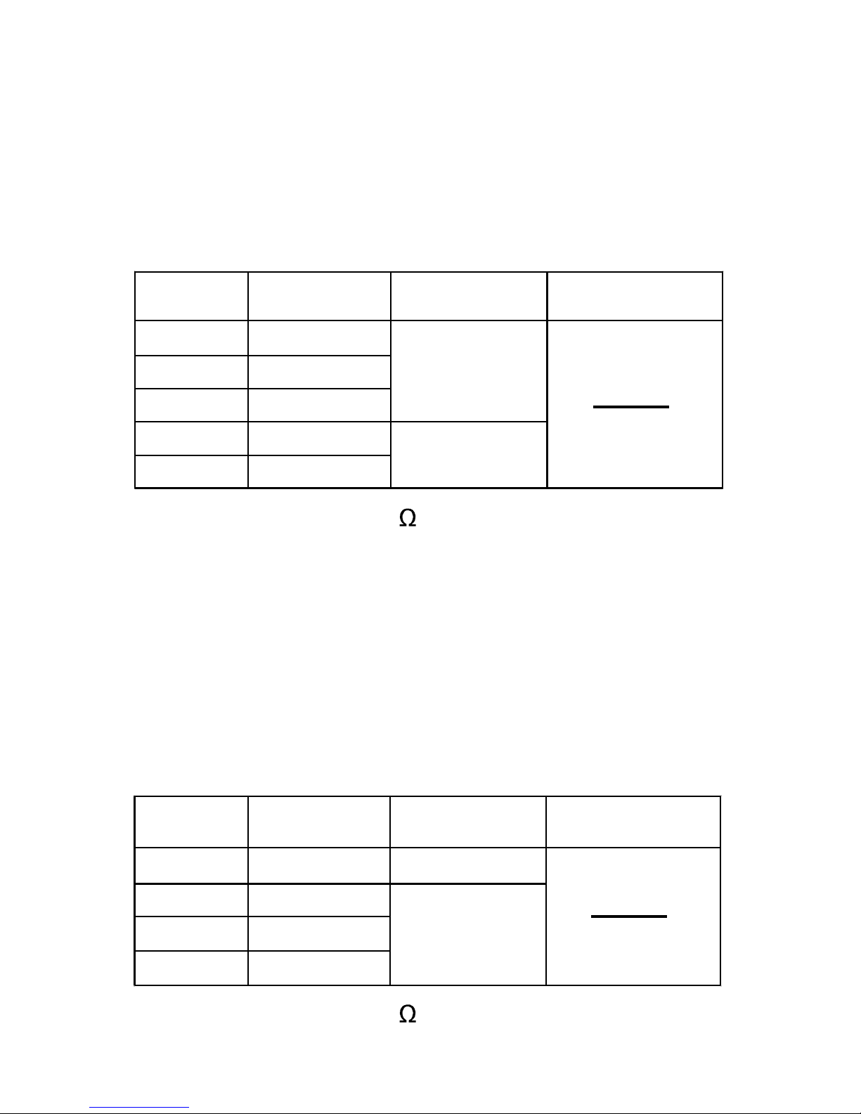
DC Voltage
Input Impedance: About 10M
Overload Protection: 600V DC/AC
[1]
When the voltage being measured is more than 600V, the
built-in buzzer will sound. When the voltage is more than 610V,
" OL " will be shown on the display.
4V
40V
400V
± (1.0% + 5)0.001V
0.01V
0.1V
± (1.2% + 8)
ResolutionRange Accuracy
AC Voltage
Overrange
Indication
[1]
Input Impedance: About 10M
600V 1V
400mV
4V
40V
600V
± (0.8% + 5)
0.1mV
0.001V
0.01V
1V
± (1.0% + 5)
ResolutionRange Accuracy
Overrange
Indication
[1]
400V 0.1V

14
Frequency Range: 50Hz ~ 1kHz
Reading: True rms
Crest Factor: 3.0
Overload Protection: 600V DC/AC
[1]
When the voltage being measured is more than 600V, the
built-in buzzer will sound. When the voltage is more than 610V,
" OL " will be shown on the display.
DC Current
Overload Protection: 12A/600V Fast fuse
Max. Allowable Input Current: 10A ( For measurements > 2A:
duration < 10 seconds, interval > 15 minutes )
[1]
When the current being measured is more than 10A, the
built-in buzzer will sound. When the current is more than 10.1A,
" OL " will be shown on the display.
± (1.2% + 5)
± (2.0% + 10)
4A 0.001A
10A 0.01A
ResolutionRange Accuracy
Overrange
Indication
[1]
AC Current
± (1.5% + 5)
± (3.0% + 10)
4A 0.001A
10A 0.01A
ResolutionRange Accuracy
Overrange
Indication
[1]
15
Frequency Range: 50Hz ~ 1kHz
Reading: True rms
Crest Factor: 3.0
Overload Protection: 12A/600V Fast fuse
Max. Allowable Input Current: 10A ( For measurements > 2A:
duration < 10 seconds, interval > 15 minutes )
[1]
When the current being measured is more than 10A, the
built-in buzzer will sound. When the current is more than 10.1A,
" OL " will be shown on the display.
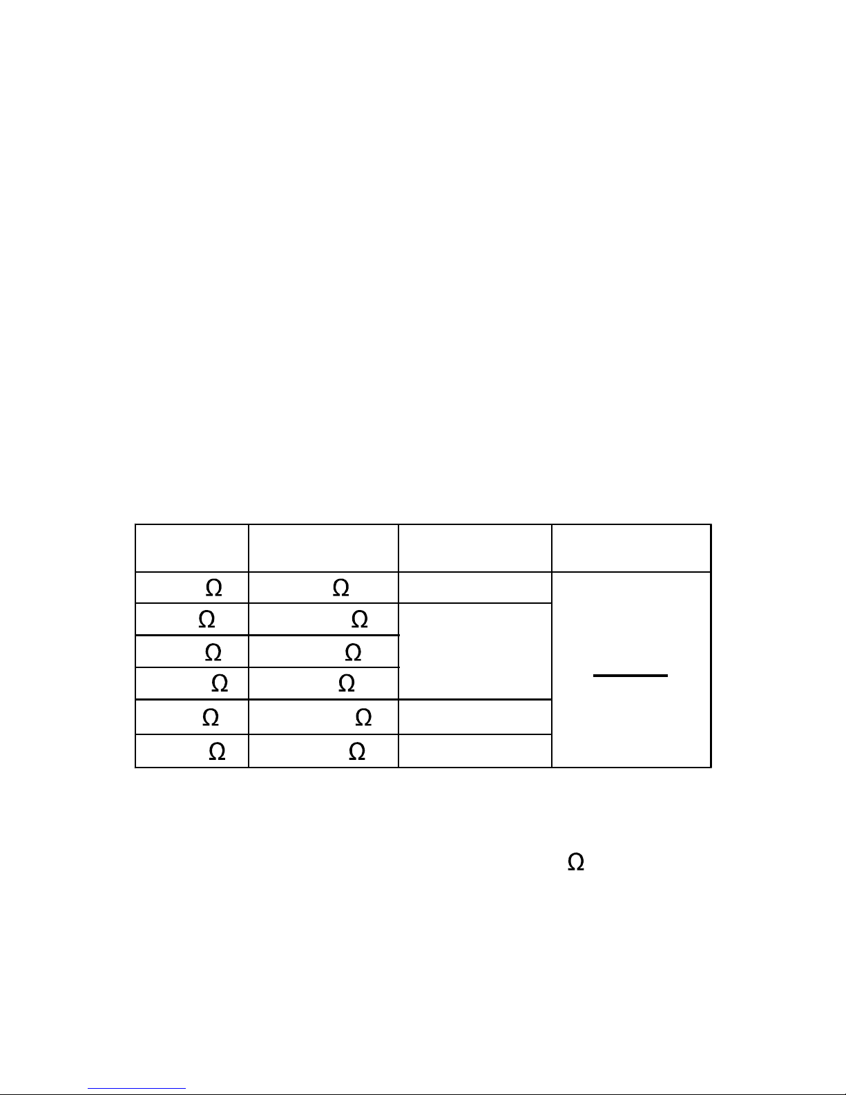
Resistance
± (1.5% + 5)
400
4k
40k
400k
4M
40M 0.01M
0.001M
0.1k
0.001k
0.01k
0.1
± (1.2% + 5)
± (1.0% + 5)
± (1.2% + 5)
ResolutionRange Accuracy
Open Circuit Voltage: About 1V
Overload Protection: 600V DC/AC
[1]
When the resistance being measured is > 40M , " OL " will be
shown on the display.
Overrange
Indication
[1]
16
ResolutionRange Accuracy
Frequency
ResolutionRange Accuracy
Duty Cycle
5% - 95% 0.1% ± (2.0% + 5)
Input Voltage: 4Vp-p ~ 10Vp-p
Frequency Range: 4Hz ~ 1kHz
Input Voltage: 1V rms ~ 20V rms
Overload Protection: 600V DC/AC
± (1.0% + 5)
9.999Hz
99.99Hz
999.9Hz
99.99kHz 0.01kHz
0.001kHz
0.1Hz
0.01Hz
0.001Hz
9.999kHz
999.9kHz 0.1kHz
9.999MHz 0.001MHz ± (2.0% + 5)

ResolutionRange Accuracy
Overload Protection: 600V DC/AC
± (5.0% + 5)
9.99nF
99.99nF
999.9nF
99.99µF 0.01µF
0.001µF
0.1nF
0.01nF
0.01nF
9.999µF
999.9µF 0.1µF
± (3.5% + 20)
± (2.5% + 5)
± (3.5% + 5)
17
Resolution
Range Accuracy
-20°C ~ 1000°C
-4°F ~ 1832°F
1°C
1°F
-4°F ~ 32°F: ± (5.0% + 8°F)
32°F ~ 752°F: ± (1.0% + 6°F)
752°F ~ 1832°F: ± (2.0% + 6°F)
-20°C ~ 0°C: ± (5.0% + 4°C)
0°C ~ 400°C: ± (1.0% + 3°C)
400°C ~ 1000°C: ± (2.0% + 3°C)
Temperature
Temperature Sensor: K Type thermocouple
Overload Protection: 600V DC/AC
Note:
1. Accuracy does not include error of the thermocouple probe.
2. Accuracy specification assumes ambient temperature is stable to
±1°C. For ambient temperature changes of ±5°C, rated accuracy
applies after 1 hour.
Capacitance

Overload Protection: 600V DC/AC
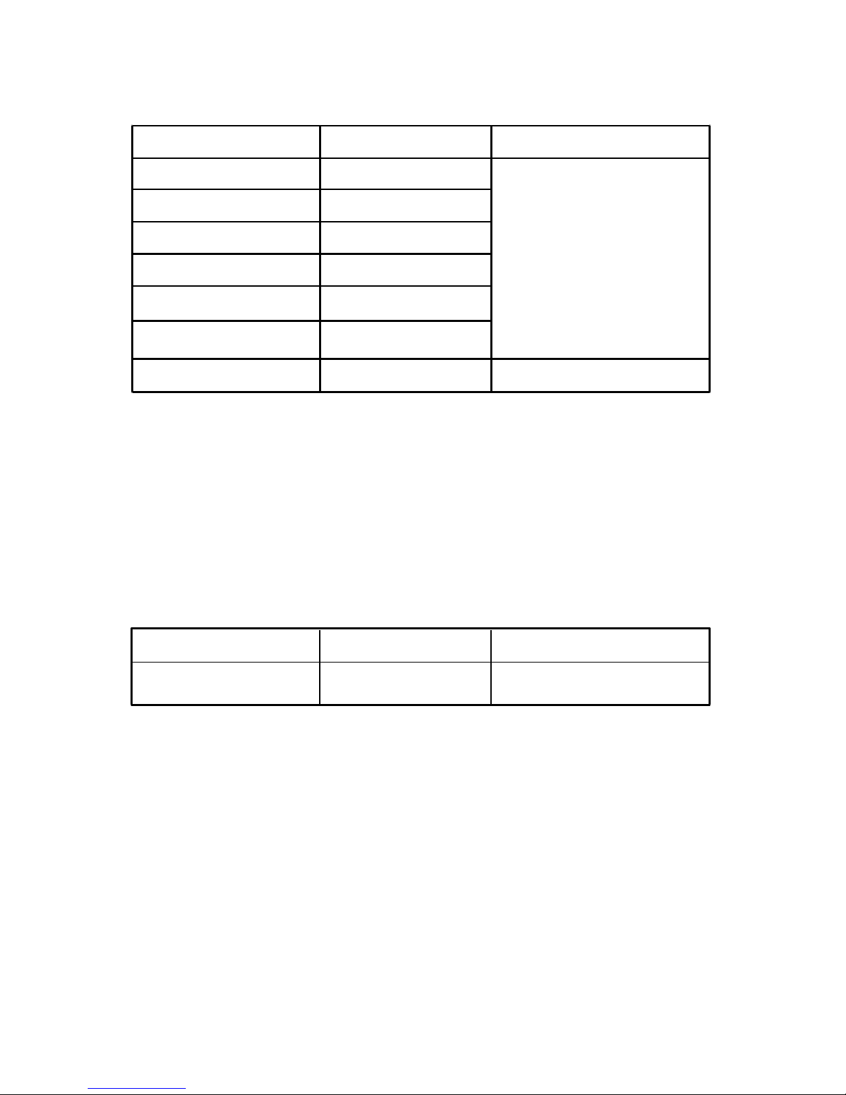
Diode and Continuity Test
Range
Open Circuit Voltage:
about 2.2V
The built-in buzzer will sound
if the resistance is less than
about 30 .
If the resistance is between
30 and 100 , the buzzer
may or may not sound.
If the resistance is more than
100 , the buzzer will not
sound.
Remark Description
18
Open Circuit Voltage:
about 4V
The approx. forward voltage
drop of the diode will be
displayed.
3. The meter's operating temperature must be between 18°C and
28°C; otherwise measurement accuracy is not guaranteed.
4. When the measured temperature is lower than -55°C ( or -68°F )
the display will show " OL " and the negative sign " - ". When the
measured temperature is higher than 1010°C ( or 1851°F ), the
display will show " OL ".

OPERATING INSTRUCTION
Data Hold Mode
Press the " HOLD " button to enter Data Hold mode. The present
reading is held on the display and the " " symbol appears on the
display as an indication.
To exit Data Hold mode, just press this button again. The " "
symbol disappears.
19
Using Relative Mode
Relative mode is available in all measurement functions except
frequency and duty cycle measurement functions. Selecting
Relative mode causes the meter to store the present reading as a
reference for subsequent measurements.
1. Set the meter in desired function.
2. Connect the meter to a desired circuit ( or object ) properly to get
a reading, which is to be used as a reference for subsequent
measurements.
3. Press the "
RELATIVE
" button. The meter enters the Relative
mode and stores the present reading as a reference for
subsequent measurements. The symbol " " appears as an
indicator and the display reads zero.

20
MIN MAX Recording Mode
The MIN MAX recording mode stores minimum and maximum input
values. When the input goes below the stored minimum value or
above the stored maximum value, the meter stores the new value.
To use the MIN MAX recording mode:
1. Make sure that the meter is in desired function.
2. Press the " MAX/MIN " button to enter MIN MAX recording mode.
The display shows the maximum reading of all readings taken
since the meter entered this mode, and " " is shown on the
display as an indication.
4. In subsequent measurements, the display shows the difference
between the reference and the new measurement.
5. To exit Relative mode, just press the "
RELATIVE
" button again.
The symbol " " disappears.
Note:
1. The meter enters manual range mode and stays in the present
range when you enter the Relative Mode.
2. When the display shows " OL ", it indicates overrange condition.
3. When you use Relative mode, the actual value of the object
under test must not exceed the full-range reading of the present
range.
4. For non-contact ac voltage detection function, Relative mode is
not available.

21
Measuring DC or AC Voltage
1. Connect the black test lead to the " COM " jack and the red test
lead to the " INPUT " jack.
2. Set the rotary switch in position.
3. If you want to measure DC voltage, press the " SELECT " button
until the display shows " ".
If you want to measure AC voltage, press the " SELECT " button
until the display shows " ".
Press this " MAX/MIN " button to toggle between the minimum
reading ( " " appears ) and the maximum reading ( " "
appears ).
3. To exit MIN MAX recording mode and erase all the stored
readings, press and hold down this " MAX/MIN " button for about
2 secs; the meter will return to normal operation.
Note:
1. When the meter enters MIN MAX recording mode, the automatic
power-off feature will be disabled, and in addition, the meter will
exit autorange mode automatically and go into manual range
mode and stay in the present range if it is in autorange mode.
2. When the display shows " OL ", it indicates overrange condition.
3. For frequency, duty cycle and capacitance measurement
functions, MIN MAX recording mode is not available.

22
Measuring DC or AC Current
1. Connect the black test lead to the " COM " jack and the red test
lead to the " 10A " jack.
2. Set the rotary switch in position.
3. If you want to measure DC current, press the " SELECT " button
until the display shows " ".
If you want to measure AC current, press the " SELECT " button
until the display shows " ".
4. Turn off power to the circuit to be tested, then discharge all
capacitors.
5. Break the circuit path to be tested, and connect the test leads in
series with the circuit.
4. Connect the test leads across the source or circuit to be tested.
5. Read the reading on the display. For DC voltage measurements,
the polarity of the red test lead connection will be indicated as
well.
Note:
1. Before the test leads are connected to the circuit to be tested, the
display may show an unstable reading. This is normal and will not
affect measurements.
2. To avoid electric shock to you or damage to the meter, do not
apply a voltage higher than 600V between the terminals.

23
6. Turn on power to the circuit, then read the display. For DC current
measurements, the polarity of the red test lead connection will be
indicated as well.
Measuring Resistance
1. Connect the black test lead to the " COM " jack and the red test
lead to the " INPUT " jack.
2. Set the rotary switch in position. Then press the "SELECT "
button until both the symbols " " and " " are absent from
the display.
3. Connect the test leads across the resistor to be tested.
4. Read the reading on the display.
Note:
1. For resistance measurements > 1M , the meter may take a few
seconds to stabilize reading. This is normal for high-resistance
measurements.
2. When the input is not connected, i.e. at open circuit, " OL" will be
displayed as an overrange indication.
3. Before measurement, disconnect all power to the circuit to be
tested and discharge all capacitors thoroughly.

Continuity Test
1. Connect the black test lead to the " COM " jack and the red test
lead to the " INPUT " jack.
2. Set the rotary switch in position. Then press the " SELECT"
button until the symbol " " appears on the display.
3. Connect the test leads across the circuit to be tested.
4. If the resistance is lower than about 30 , the built-in buzzer will
sound.
Note:
Before test, disconnect all power to the circuit to be tested and
discharge all capacitors thoroughly.
24
Diode Test
1. Connect the black test lead to the " COM " jack and the red test
lead to the " INPUT " jack. ( Note: The polarity of the red test lead
is positive "+". )
2. Set the rotary switch in position. Then press the "SELECT "
button until the symbol " " appears on the display.
3. Connect the red test lead to the anode of the diode to be tested
and the black test lead to the cathode of the diode.
4. The display shows the approximate forward voltage drop of the
diode. If the connection is reversed, " OL " will be shown on the
display.

25
Measuring Capacitance
1. Connect the black test lead to the " COM " jack and the red test
lead to the " INPUT " jack.
2. Set the rotary switch in position.
3. Thoroughly discharge the capacitor to be tested, and then connect
the test leads to the two leads of the capacitor.
Note: When measuring electrolytic capacitor, the black test lead
must be connected to the cathode of the capacitor and the
red test lead must be connected to the anode of the
capacitor.
4. Wait until the reading is stable, then read the reading on the
display.
Note:
1. Because of the stray capacitance of the test leads and the input
circuit of the meter, the display may show a reading other than
zero before the test leads are connected to the capacitor to be
tested. It is normal and this reading must be subtracted from the
subsequent measurements.
2. Before measurement, make sure that the capacitor to be tested
has been discharged thoroughly.
3. For measurements > 10µF, it may take about 30 seconds for the
meter to stabilize reading.

26
Measuring Frequency
1. Connect the black test lead to the " COM " jack and the red test
lead to the " INPUT " jack.
2. Set the rotary switch in position. Then press the
"SELECT " button until " Hz " appears on the display.
3. Connect the test leads across the source or circuit to be tested.
4. Read the reading on the display.
Note:
1. The voltage of input signal should be between 1V rms and 20V
rms. The higher the frequency of the signal, the higher the
required input voltage.
2. For measurements < 10Hz, the amplitude of the input signal must
be more than 2V rms.
Measuring Duty Cycle
1. Connect the black test lead to the " COM " jack and the red test
lead to the " INPUT " jack.
2. Set the rotary switch in position. Then press the "SELECT "
button until " % " appears on the display.
3. Connect the test leads to the circuit to be tested.
4. The reading on the display is the duty cycle reading of the square
wave being measured.

27
Note:
1. The voltage of the input signal should be between 4Vp-p and
10Vp-p.
2. After you remove the measured signal from the meter, its reading
may still remain on the display. Pressing the " SELECT" button
twice will zero the display.
1. Set the rotary switch to position.
2. Press the "SELECT" button to select celsius or fahrenheit
temperature measurement, the display will show the
corresponding unit.
To avoid possible damage to the meter or other
equipment, remember that while the meter is rated
for -20°C to +1000°C and -4°F to 1832°F, the K Type
Thermocouple provided with the meter is rated to
250°C. For temperature out of that range, use a
higher rated thermocouple.
The K Type Thermocouple provided with the meter
is a present, it is not professional and can only be
used for non-critical measurements.
For accurate measurements, use a professional
thermocouple.
Note
Measuring Temperature

28
3. Connect the negative " - " plug of the K type thermocouple to
the " COM " jack and the positive " + " plug of the K type
thermocouple to the " INPUT " jack.
4. Connect the sensing end of the thermocouple to the object to be
tested.
5. Wait a while, then read the reading on the display.
Non-Contact AC Voltage Detection
1. Set the rotary switch in NCV position. The display shows " EF "
( refer to Figure 3 ).
2. Move the top of the meter close to the object to be tested. When
the meter detects ac voltage, the built-in buzzer will beep and
the display will indicate the intensity of the detected electric field.
The intensity of the detected electrical field is indicated by the
number of the bar-graph segments at the vertical center of the
display and the beeping rate of the built-in buzzer. The higher the
intensity of the detected electric field, the larger the number of the
bar-graph segments ( refer to Figures 4 and 5 ), and the faster
the beeping rate of the buzzer.
Figure 3

29
Figure 4 Figure 5
Note:
1. If the magnitude of an ac voltage is not within the meter's
detecting capacity or the distance between an ac voltage and the
meter is not within the meter's detecting capacity, the meter can
not detect this ac voltage.
2. Before use, verify the meter's operation by detecting a known ac
voltage.
3. Because of the meter's detection limit, a line ( or conductor )
under test may be live even if the built-in buzzer does not beep
and the display does not indicate the intensity of electric field.
To avoid electric shock, do not touch any conductor with hand or
skin.
4. The meter's electric field intensity indication is affected by the
magnitude of the ac voltage of the conductor under test, the
distance between the meter and the conductor, the insulation of
the conductor, and etc.

30
Automatic Power-Off
The meter will turn off automatically and go into Sleep mode if you
have not operated the meter for about 15 minutes. To arouse the
meter from Sleep, just press a button or turn the rotary switch.
To disable the automatic power-off function, turn the rotary switch
from the " OFF " position to other position while holding down the
" SELECT " button; the display will not show the " " symbol.
Bluetooth Communication
This multimeter has Bluetooth communication function. To enable
this function, press and hold down the " SELECT " button for about
2 secs; the symbol " " will appear on the display as an indication.
By using Bluetooth communication function, this multimeter can
communicate with Android or iOS based smart device with Bluetooth
connectivity. After you install and run the free communication app on
the Android or iOS based smart device and turn on the Bluetooth
function of this device, you can monitor the multimeter measurements,
view graphical plot of measurement readings and etc through this
app. For more detailed information about this app, please see the
operation instruction of this app.

General Maintenance
Periodically wipe the case with a damp cloth and a little mild detergent.
Do not use abrasives or solvents.
Dirt or moisture in the terminals can affect readings.
Clean the terminals as follows:
1. Turn off the meter and remove all the test leads from the meter.
2. Shake out any dirt which may exist in the terminals.
3. Soak a new swab with alcohol.
4. Work the swab around in each terminal.
If the meter does not seem to work properly, check and replace ( as
needed ) the batteries or fuse; and/or review this manual to verify
correct operation.
31
MAINTENANCE
Warning
Except replacing fuse and battery, never attempt to repair or
service the meter.
Store the meter in a dry place when not in use. Don't store it in an
environment with intense electromagnetic field.

32
To avoid false readings, which could lead to possible
electric shock or personal injury, replace the batteries
as soon as the low battery indicator ( ) appears.
To prevent damage, electric shock or personal injury,
use only replacement fuse specified.
Before opening the battery cover or the case, turn off
the meter and remove the test leads.
Warning
Battery and Fuse Replacement
When the symbol " " appears on the display or if the meter
operates abnormally or can not be turned on, replace the batteries
immediately. To replace the batteries, remove the screw on the battery
cover and remove the battery cover. Replace the exhausted batteries
with new ones of the same type ( 1.5V battery, AAA or equivalent ),
make sure that the polarity connections are correct. Reinstall the
battery cover and the screw.
To replace fuse, remove the screws on the back cover and remove
the back cover. Replace the blown fuse with a new one of the same
ratings. Reinstall the back cover and the screws.
The meter uses one fuse: 12A/600V, Fast action, Min. Interrupt Rating
10kA, Ø 6.35X32mm

ACCESSORIES
Manual: 1 piece
Test Lead: 1 pair
Alligator Clip: 1 pair
Adapter: 1 piece ( for capacitance measurements )
PRESENT
K Type Thermocouple: 1 piece
NOTE
1. This manual is subject to change without notice.
2. Our company will not take the other responsibilities for any loss.
3. The contents of this manual can not be used as the reason to use
the meter for any special application.
33

DISPOSAL OF THIS ARTICLE
Dear Customer,
If you at some point intend to dispose of this article,
then please keep in mind that many of its
components consist of valuable materials, which
can be recycled.
Please do not discharge it in the garbage bin, but
check with your local council for recycling facilities
in your area.
V180331
34
Zhangzhou Eastern Intelligent Meter Co., Ltd
Eastern Industrial Park, Jintang Road, Jinfeng
Economic Development Zone, Xiangcheng District,
Zhangzhou, Fujian, China

 Loading...