


Gasoline Generator
Generatori a Benzina
Instruction manual
Libretto Istruzioni

CONTENTS
1. SAFETY........................................................................................................................................................................................................................................5
1) Safety Label Locations
......................................................................................................................................................................................5
2) Safety Information
..................................................................................................................................................................................................6
2. COMPONENT IDENTIFICATION
..................................................................................................................................................................8
3. CONTROLS
.........................................................................................................................................................................................................................10
1) Engine Switch
............................................................................................................................................................................................................10
2) Recoil Starter
..............................................................................................................................................................................................................10
3) Fuel Valve
........................................................................................................................................................................................................................10
4) Choke
.................................................................................................................................................................................................................................11
5) Circuit Breaker
........................................................................................................................................................................................................12
6) Ground Terminal
...................................................................................................................................................................................................12
7) Oil Alert System
.....................................................................................................................................................................................................12
4. GENERATOR USE
....................................................................................................................................................................................................13
1) Connections to a Building’s Electrical System
................................................................................................................13
2) Ground System
........................................................................................................................................................................................................13
3) AC Applications
.....................................................................................................................................................................................................14
4) AC Operation
..............................................................................................................................................................................................................15
5) DC Operation
.............................................................................................................................................................................................................15
6) High Altitude Operation
.................................................................................................................................................................................17
5. PREOPERATION CHECK
..................................................................................................................................................................................17
1) Engine Oil
........................................................................................................................................................................................................................18
2) Fuel
.........................................................................................................................................................................................................................................19
6. STARTING/STOPPING THE ENGINE
............................................................................................................................................... 21
7. MAINTENANCE
............................................................................................................................................................................................................ 22
1) Maintenance Schedule
................................................................................................................................................................................. 22
2) Tool Kit
............................................................................................................................................................................................................................ 23
3) Engine Oil Change
.............................................................................................................................................................................................. 23
4) Air Cleaner Service
............................................................................................................................................................................................. 24
5) Fuel Sediment Cup
............................................................................................................................................................................................ 25
6) Spark plug
................................................................................................................................................................................................................... 25
7) Spark Arrester Maintenance
................................................................................................................................................................. 27
8. TRANSPORTING/STOREGE
....................................................................................................................................................................... 29
9. TROUBLESHOTTING
........................................................................................................................................................................................... 31
10. WIRING DIAGRAM
.................................................................................................................................................................................................. 32
11. SPECIFICATIONS
..................................................................................................................................................................................................... 35
12. OPTIONAL PARTS
................................................................................................................................................................................................... 37
2
CONTENTS
GB

INDICE
1. SICUREZZA ....................................................................................................................................................................................... 40
1) ) Posizione delle targhette disicurezza ................................................................................................................. 40
2) Informazioni per la sicurezza........................................................................................................................................ 41
2. IDENTIFICAZIONE DEI COMPONENTI ....................................................................................................................... 43
3. COMANDI ............................................................................................................................................................................................. 45
1) Interruttore del motore......................................................................................................................................................... 45
2) Motorino di avviamento a corda ................................................................................................................................. 45
3) Valvola del carburante ......................................................................................................................................................... 45
4) Valvola dell’aria ......................................................................................................................................................................... 46
5) Interruttore salvavita ............................................................................................................................................................. 47
6) Morsetto di messa a terra ............................................................................................................................................... 47
7) Sistema di controllo dell’olio .......................................................................................................................................... 47
4. USO DEL GENERATORE ....................................................................................................................................................... 48
1) Collegamenti al sistema elettrico di un edificio ............................................................................................ 48
2) Sistema di messa a terra .................................................................................................................................................. 48
3) Apparecchi a corrente alternata AC......................................................................................................................... 49
4) Funzionamento con corrente alternata AC........................................................................................................ 50
5) Funzionamento con corrente diretta DC.............................................................................................................. 50
6) Funzionamento a quote elevate .................................................................................................................................. 52
5. CONTROLLO PREOPERATIVO ......................................................................................................................................... 53
1) Olio del motore ......................................................................................................................................................................... 53
2) Carburante..................................................................................................................................................................................... 54
6. ACCENSIONE/SPEGNIMENTO DEL MOTORE................................................................................................... 56
7. MANUTENZIONE .......................................................................................................................................................................... 57
1) Tabella di manutenzione.................................................................................................................................................... 57
2) Kit di attrezzi ............................................................................................................................................................................... 58
3) Cambio dell’olio del motore .......................................................................................................................................... 59
4) Manutenzione del filtro dell’aria ................................................................................................................................. 59
5) Pulizia della vasca di sedimentazione del carburante.............................................................................. 60
6) Manutenzione delle candele........................................................................................................................................... 60
7) Manutenzione del parascintille..................................................................................................................................... 62
8. TRASPORTO/CUSTODIA ...................................................................................................................................................... 64
9. INDIVIDUAZIONE ED ELIMINAZIONE DI GUASTI ........................................................................................... 66
10. SCHEMA DEL CABLAGGIO ................................................................................................................................................ 67
11. SPECIFICHE ...................................................................................................................................................................................... 70
12. COMPONENTI FACOLTATIVI ............................................................................................................................................ 72
INDICE
I
3

Thank you for purchasing our generator. We want to help you get the best results from
your new generator and to operate it safety.
This manual contains the information on how to do that; please read it carefully.
All information and specifications in this publication is based on the lastest product
information available at the time of printing.
DC type is equipped for DC outlet. DDC type is equipped for both eletric starting and
DC outlet.
This manual should be considered a permanent part of the generator and should
remain with it if is resold.
Safety Messages
Your safety and the safety of others are very important. We have provided important
safety messages in this manual and on the generator. Please read these messages
carefully.
A safety message alerts you to potential hazard that could hurt your or others. Each
safety message is proceded by a safety alert symbols and one of tree words:
DANGER, WARNING, or CAUTION. These mean:
Damage Prevention Messages
Other important messages are preceded by the word NOTICE. this word means:
The purpose of these messages is to help prevent damage to your generator, other
property, or the environment.
DANGER
WARNING
CAUTION
You WILL be KILLED or SERIOUSLY HURT if you don’t
follow instructions.
You CAN be KILLED or SERIOUSLY HURT if you don’t
follow instructions.
You can be HURT if you don’t follow instructions.
NOTICE
Your generator or other property could be damaged if you
don’t follow instructions.
GB
4

1. SAFETY
1) SAFETY LABEL LOCATION
These labels warn you of potential hazards that can cause serious injury. Read them
carefully.
If a label comes off or becomes hard to read, contact your generator dealer for a
replacement.
SAFETY
WARNING
Check that there is no any
fuel spilling or fuel leakage.
Filling fuel before stalling the
engine is forbidden.
Among engine exhaust emissions, there toxic
CO.so never use in an enclosed room without
good ventilation.
WARNING
Before operation, be sure to add specified
engine oil into the crankcase. Please refer
to the OWNER’S MANUAL for further
information
CAUTION
ST
GB
5

2) SAFETY INFORMATION
Our generator are designed to give safe and dependeble service if operated acording
to instructions. Read and understand this owner’s manual before operating your generator.
You can help prevent accidents by being familiar with your generator’s controls, and by
observing safe operating procedures.
Operator Responsability
• Know how to stop the generator quickly in case of emergency.
• Understand the use of all generator controls, output receptacles, and connections.
• Be sure that anyone who operates the generator receives proper instruction. Do not
let children operate the generator without parental supervision. Keep children and
pets away from the area of operation.
• Place the generator on a firm, level surface and avoid loose sand or snow. If the
generator is tilted or overturned, fuel spillage may result. Also, if the generator is
overturned or sinks into a soft surface, sand, dirt, or water may enter the generator.
SAFETY
CAUTION
HIGH TEMPERATURE PART! DONT TOUCH IT!
MUFFLER! HOT!
GB
6

Carbon Monoxide Hazards
• Exhaust contains poisonous carbon monoxide, a colorless and odorless gas.
Breating exhaust can cause loss of consciousness and may lead to death.
• If you run the generator in an area that is confined, or even partially enclosed, the air
you breathe could contain a dangerous amount of exhaust gas. To keep exhaust gas
from building up, provide adequate ventilation.
Eletric Shock Hazards
• The generator produces enough eletric power to cause a serious shock or
electrocution if misuded.
• Using a generator or electrical appliance in wet condictions, such as rain or snow,
or near a pool or sprinkler system, or when your hands are wet, could result in
electrocution. Keep the generator dry.
• If the generator is stored outdoors, unprotected from the weather, check all
electrical components on the control panel, before each use. Moisture or ice can cause
a malfunction or short circuit in eletrical conponents wich could result in electrocution.
• Do not connect to a building’s electrical system unless an isolation switch has been
installed by a qualified electrician.
Fire and Burn Hazards
• The exhaust system gets hot enough to ignite some materials.
- Keep the generator at least 1 meter (3 feet) away from buildings and other
equipment during operation.
- Do not enclose the generator in any structure.
- Keep flammable materials away from the generator.
• The muffler becomes very hot during operation and remains hot for a while after
stopping the engine. Be careful not to touch the muffler while it is hot. Let the engine
cool before storing the generator indoors.
• Gasoline is extremely flammable and is explosive under certain conditions. Do not
smoke or allow flames or sparks where the generator is refueled or where the gasoline
is stored. Refuel in a well-ventilaed area with the engine stopped.
• Fuel vapors are extremely flammable and may ignite after the engine has started.
Make sure that any spilled fuel has been wiped up beore starting the generator.
SAFETY
GB
7

2. COMPONENT IDENTIFICATION
COMPONENT IDENTIFICATION
AC RECEPTACLES
AC CIRCUIT
BREAKER
GROUND
TERMINAL
DC RECEPTACLES
VOLTMETER
DC PROTECTOR
RECOIL STARTER GRIP
AIR CLEANER
FUEL VALVE
CHOKE LEVER
ENGINE SWITCH
ENGINE TYPE & SERIAL NUMBER
OIL FITER CAP
GB
8

Record the engine serial numbers for your future reference.
Refer to these serial number when ordering parts, and when making technical.
Engine serial number:
COMPONENT IDENTIFICATION
GROUND TERMINAL
FUEL TANK CAP
FUEL METER
MUFFLER
SPARK PLUG CAP
VOLMETER
CIRCUIT BREAKER
RECEPTACLE
AC OUTPUT TERMINAL
THREE PHASE TYPE
GB
9

3. CONTROLS
1) Engine Switch
The start and stop the engine.
Switch position:
OFF: To stop the engine.
ON: To run the engine.
To engine with electric starter, include the START position.
2) Recoil Starter
To start the engine, pull the starte grip lightly until resistance is felt, then pull briskly.
3) Fuel Valve
The fuel valve is located between the fuel tank and carburetor. When the valve lever is
in the ON position, fuel is allowed to flow from the fuel tank to the carburetor. Be sure
to return the lever to OFF after stopping the engine.
CONTROLS
ENGINE SWITCH
OFF
ON
ENGINE SWITCH
OFF
ON
ENGINE SWITCH
OFF
ON
NOTICE
Do not allow the starter to snap back aganist the engine.
Return it gently to prevent damage to the starter.
STARTER GRIP
STARTER GRIP
GB
10

4) Choke
The choke is used to provide an enriched fuel mixture when starting a cold engine. It
can be opened and closed by operating the choke lever or choke rod manually.
Move the lever or the rod to the CLOSE position to enrich the mixture.
CONTROLS
Valve lever
ON
OFF
Valve lever
CHOKE ROD
OPEN
CLOSE
CHOKE LEVER
CLOSED
CHOKE LEVER
OPEN
ON
OFF
OPEN
CLOSE
OPEN
GB
11

4) Circuit Breaker
The circuit breaker will automatically switch OFF if there is a short circuit or a significant
overlaod of the generator at the receptacle. If the circuit breaker is switched OFF
automatically, check that the appliance is working properly and does not exceed the
rated load capacity of the circuit before swicthing the circuit breaker ON again.
The circuit breaker may be used to switch the generator power ON or OFF.
6) Ground Terminal
The generator ground terminal is connected
to the panel of the generator, the metal
non-current carrying parts of the generator,
and the ground terminals of each receptacle.
Before using the ground terminal, consult a
qualified electrician, eletrical inspector or
local agency having jurisdiction for local
codes or ordinances that apply to the
intended use of the generator.
7) Oil Alert System
The oil alert system is designed to prevent engine damage caused by an insufficient
amount of oil in the crankcase. Before the oil level in the crankcase can fall below a
safe limit, the oil alert system will automatically shut down the engine (the engine
switch wil remain in the ON position). The oil alert system shuts down the engine and
the engine will not start. If this occurs, please check engine oil first.
CONTROLS
CIRCUIT BREAKER
GROUND
TERMINAL
OFF
ON
GB
12

4. GENERATOR USE
1) Connections to a Building’s Electrical System
Connections for standby power to a building’s electrical system must be made by a
qualified electrician. The connection must isolate the generator power from utility power,
and must comply with all applicable laws and electrical codes.
Improper connections to a building’s electrical syatem, can allow
electrical current from the generator to backfeed into the utility lines.
Such backfeed may electrocute utility company workers or others who contact the
lines during a power outage. Consult the utility company or a qualified electrician.
Improper connections to a building’s electrical system can allow
electrical current from the utility company to backfeed into the
generator. When utility power is restored , the generator may explode, burn, or
cause fires in the building’s electrical system.
2) Ground System
To prevent electrical shock from faulty applicances, the generator should be grounded.
Connect a lenght of heavy wire between the ground terminal and the ground source.
The generators have a system ground that connects generator frame components to
the ground terminals in the AC output receptacles. The system ground is not connected
to the AC neutral wire. If the generator is tested by a receptacle tester, it will not show
the same ground circuit condition as for a home receptacle.
Special Requirements
There may be Federal or State Occupational Safety and Health Administration (OSHA)
GENERATOR USE
GROUND
TERMINAL
WARNING
CAUTION
GB
13

regulation, local codes, or ordinances that apply to the intended use of the generator.
Please consult a qualified electrician, elctrical inspector, or the local agency having
jurisdiction.
• In some areas, generators are required to be registered with local utility companies.
• If the generator is used at a construction site, there may be additional regulations
which must be observed.
3) AC Applications
Before connecting an appliance or power cord to the generator:
• Make sure that it is in good working order. Faulty appliances or power cords can
create a potential for electrical shock.
• If an appliance begins to operate abnormally, becomes sluggish or stops suddenly,
turn it off immediately. Disconnect the appliance, and determine whether the problem
is the appliance, or if the rated load capacity of the generator has been exceeded.
• Make sure that the electrical rating of the tool or appliance does not exceed that of
the generator. Never exceed the maximum power rating of the generator. Power levels
between rated and maximum may be used for no more than 30 minutes.
Substantial overloading will switch off the circuit breaker.
Exceeding the time limit maximum power operation or slightly
overloading the generator may not switch the circuit breaker OFF, but will
shorten the service life of the generator.
Limit operation requiring maximum power to 30 minutes.
Maximum power of the LC 1800 DC generator is: 1.5 kW
Maximum power of the LC 2500 DC generator is: 2.2 kW
Maximum power of the LC 3800 DDC generator is: 3.1 kW
Maximum power of the LC 5000 DDC generator is: 4.4 kW
Maximum power of the LC 6500 DDC generator is: 5.5 kW
For continuos operation, do not exceed the rated power.
Rated power of the LC 1800 DC generator is: 1.3 kW
Rated power of the LC 2500 DC generator is: 2.0 kW
Rated power of the LC 3800 DDC generator is: 2.8 kW
Rated power of the LC 5000 DDC generator is: 4.0 kW
Rated power of the LC 6500 DDC generator is: 5.0 kW
In either case, the total power requirements (kW) of all appliances connected must be
GENERATOR USE
NOTICE
GB
14

considered. Appliance and power tool manufacturers usually list rating information near
the model number or serial number.
4) AC Operation
1
Start the engine.
2 Switch the AC circuit breaker ON.
Rated current of the AC circuit breaker:
LC 1800 DC: 7 A
LC 2500 DC: 10 A
LC 3800 DDC: 13 A
LC 5000 DDC: 19 A
LC 6500 DDC: 23 A
3 Plug in the appliance.
Most motorized appliances require more than their rated wattage for startup.
Do not exeed the current limit specified for any one receptacle. If an overload circuit
causes the AC circuit breaker to switch OFF, reduce the electrical load on the circuit,
wait a few minutes and then reset the circuit breaker.
5) DC OPERATION
DC terminals
The DC terminals may ONLY be used
for charging 12 volt automative type
batteries.
The terminal are colored red identify the positive (+) terminal and black to identify
the negative (-) terminal. The battery must be connected to the generator DC terminals
with the proper polarity (battery positive to generator red terminal and battery negative
to the generator black terminal).
GENERATOR USE
NEGATIVE TERMINAL (BLACK)
POSITIVE TERMINAL (RED)
DC PROTECTOR
GB
15

DC Circuit Protector
The DC circuit protector (rated current: 10A) automatically shuts off the DC battery
charging circuit when the DC circuit is overloaded, when there is a problem with the
battery, or the connections between the battery and the genrator are improper.
The indicator inside the DC circuit protector button will pop to show that the DC circuit
protector has switched off. Wait a few minutes and push the button in to reset the DC
circuit protector.
Connecting the battery cables:
1
Before connecting charging cables to a battery that is installed in a vehicle, disconnect
the vehicle’s grounded battery cable.
The battery gives off explosive gases; keep sparks, flames and cigarettes
away. Provide adequate ventilation when charging or using batteries.
2 Connect the positive (+) battery cable to the battery positive (+) terminal.
3 Connect the other end of the positive (+) battery cable to the generator.
4 Connect the negative (-) battery cable to the battery negative (-) terminal.
5 Connect the other end of the negative (-) battery cable to the generator.
6 Start the generator.
Do not start the vehicle while the battery charging cables are
connected and the generator is running. The vehicle or the
generator may be damaged.
An overload DC circuit, excessive current draw by the battery, or a wiring problem
will trip the DC circuit protector (PUSH button extends out). If this happens, wait a few
minutes before pushing in the circuit protector to resume operation. If the circuit
protector continues to go OFF, discontinue charging and see your authorized generator
dealer.
GENERATOR USE
NOTICE
WARNING
GB
16

Disconnecting the battery cables:
1
Stop the engine.
2 Disconnect the negative (-) battery cable from the generator negative (-) terminal.
3 Disconnect the other end of the negative (-) battery cable from the battery negative
(-) terminal.
4 Disconnect the positive (+) battery cable from the generator positive (+) terminal.
5 Disconnect the other end of the positive (+) battery cable to the battery positive (+)
terminal.
6 Connect the vehicle ground cable to the battery negative (-) terminal.
7 Reconnect the vehicle grounded battery cable.
6) High Altitude Operation
At high altitude, the standard carburetor air-fuel mixture will be excessively rich.
Performance will decrease, and fuel consumption will increase.
High altitude performance can be improved by installing a smaller diameter main fuel
jet in the carburetor and readjusting the pilot screw. If you always operate the engine
at
altitudes higher than 5000 feet (1500 meters) above sea level, have an authorized
generator dealer perform this carburetor modification.
Even with suitable carburetor jetting, engine horsepower will decrease approzimately
3.5% for each 1000 foot (300 meters) increase in altitude. The effect of altitude on
horsepower will be greater than this if no carburetor modification is made.
If a engine jetted for high altitude is used at a lower altitude,
the lean air fu mixture will reduce performance and may over-
heat and seriously damage the engine.
GENERATOR USE
NOTICE
GB
17

5. PRE-OPERATION CHECK
1) Engine Oil
Engine oil is a major factor affecting engine performance and
service life. Non-detergent and 2-stroke engine oils will damage
the engine and are not recommended.
Check the oil level BEFORE EACH USE with the generator on a level surface with the
engine stopped.
Use 4-stroke oil, premium quality motor oil certified to meet or exceed U.S. automobile
manufacturer’s requirements for Service Classification SG, SF/CC, CD. Motor oils
classified SG, SF/CC, CD will show this
designation on the container.
SAE 10W-30 is recommended for general,
all-temperature use. Other viscosities
shown in the chart may be used when the
average temperature in your area is within
the indicated range.
1. Remove the oil filter cap and wipe the dipstick clean.
2. Check the oil level by inserting the dipstick into the filler neck without screwing it in.
3. If the level is low, add the reccommended oil to the upper mark on the dipstick.
PRE-OPERATION CHECK
NOTICE
AMBIENT TEMPERATURE
OIL FILLER HOLE
OIL FILLER CAP
UPPER LEVEL
OIL FILLER CAP
GB
18

2) Fuel
1. Check the fuel level gauge, or check the fuel level after opening the fuel tank cap.
2. Refill the tank if the fuel level is low. Do not fill above the shoulder of the fuel stranier.
• KEEP OUT OF REACH OF CHILDREN.
• Gasoline is extremely flammable and is explosive under certain
conditions.
• Refuel in a well-ventilated area with the engine stopped. Do not smoke or allow
flames or sparks in the area where the engine is refueled or where gasoline is
stored.
• Do not overfill the fuel tank (there should be no fuel in the filler neck). After
refueling, make sure the tank cap is closed properly and securely. Be careful not
to spill fuel when refueling. Spilled fuel vapor may ignite. If any fuel is spilled,
make sure the area is dry before starting the engine.
• Avoid repeated or prolonged contact with skin or breathing of vapor.
Fuel tank capacity:
LC 1800 DC - LC 2500 DC is: 15.0 L
LC 3800 DDC - LC 5000 DDC - LC 6500 DDC is: 25.0 L
Use gasoline with a pump octane rating of 90 or higher.
We recommend unleaded gasoline because it produces fewer engine and spark plug
deposits and extends exhaust system life.
Never use stale or contaminated gasoline or oil/gasoline mixture. Avoid getting dirt or
water in the fuel tank.
Occasionally you may hear light “spark knock” or “pinging” (metallic rapping noise)
while operating under heavy loads. This is no cause for concern.
PRE-OPERATION CHECK
FUEL LEVEL GAUGE
EMPTY
FUEL TANK CAP
UPPER FUEL LEVER
WARNING
OPEN
CLOSE
GB
FULL
19

If spark knock or pinging occurs at a steady engine speed, under normal load, change
brands of gasoline. If spark knock or pinging persists, see an authorized generator
dealer.
Running the engine with persistent spark knock or pinging can
cause engine damage.
Running the engine with persistent spark knock or pinging is misuse, and the Distributor’s
Limited Warranty does not cover parts damaged by misuse.
Oxygenated Fuels
Some gasoline are blended with alcohol or an ether compound to increase the octane.
These gasoline are collectively referred to as oxygenated fuels. Some areas of the United
States use oxygenated fuels to help meet clean air standards.
If you use an oxygenated fuel, be sure its pump octane rating is 86 or higher.
Ethanol (ethyl or grain alcohol)
Gasoline containing more than 10% ethanol by volume may cause starting and/or
performance problems. Gasoline containing ethanol may be marketed under the name
“Gasohol”.
Methanol (methyl or wood alcohol)
Gasoline containing methanol must contain cosolvents and corrosion inhibitors to
protect the fuel system. Gasoline containing more than 5% methanol by volume may
cause starting and/or performance problems and may damage metal, rubber and
plastic parts of your fuel system.
MTBE (methyl tertiary butyl ether)
You may use gasoline containing up to 5% MTBE by volume.
Before using an oxygenated fuel, try to confirm the fuel’s contents. Some states (provinces
in Canada) require this information to be posted on the pump. If you notice any undesirable
operating symptoms, switch to a conventional unleaded gasoline. Fuel system damage
or performance problems resulting from the use of an oxigenated fuel are not the
responsibility of manufacturer and are not covered under warranty.
Oxygenated fuels can damage paint and plastic. Be careful not
to spill fuel when filling your fuel tank. Damage caused by spilled
fuel is not covered under warranty.
PRE-OPERATION CHECK
NOTICE
NOTICE
GB
20

6. STARTING/STOPPING THE ENGINE
1) Starting the engine
1 Make sure that the AC circuit breaker is in the OFF position. The generator may be
hard to start if a load is connected.
2 Turn the fuel valve to the ON position.
3 Turn the choke lever or to the CLOSE position, or pull the choke rod out to the CLOSE
position.
4 Start the engine.
• With recoil starter:
Turn the engine switch to the ON position.
Pull the starter grip until compression is felt, then pull briskly.
Do not allow the starter grip to snap back against the engine.
Return it gently to prevent damage to the starter or housing.
• With electric starter:
Turn the engine switch to the START position and hold it there for 5 seconds or until the
engine starts.
Operating the starter motor for more than 5 seconds can damage
the motor. if the engine fails to start, release the switch and wait
10 seconds before operating the starter again. If the speed of the starter motor
drops after a period of time, it is an indication that the battery should be
recharged.
When the engine starts, allow the engine switch to return to the ON position.
5 Turn the choke lever or push the choke rod to the OPEN position as the engine warms
up.
2) Stopping the engine
In an emergency:
To stop the engine in an emergency, move the engine switch to the OFF position
In normal use:
1 Turn the AC circuit breaker to the OFF position. Disconnect the DC battery charging
cables.
2 Turn the engine switch to the OFF position.
3 Turn the fuel valve to the OFF position.
PRE-OPERATION CHECK
NOTICE
GB
NOTICE
21

REGULAR SERVICE PERIOD
Performed at every indicated month
operating hour interval, wichever comes first.
ITEM
Engine oil
Air cleaner
Sediment Cup
Spark plug
Spark arrester
Valve clearance
Fuel tank and strainer
Cylinder head
Fuel line
Check level
Change
Check
Clean
Clean
Clean
Chek-Clean
Chek-Adjust
Clean
Clean
Check (Replace if
necessary)
Each
use
First
month or
20 Hrs.
(3)
Every
months or 50
Hrs. (3)
Every 6
months or
100 Hrs.
(3)
Every year
or
300 Hrs.
(3)
(1)
(2)
(2)
Every 300 hours (2)
Every 2 years (2)
7. MAINTENANCE
Good maintence is essential for safe, economical, and trouble-free operation. It wil also
help reduce air pollution.
Exhaust gas contains poisonous carbon monoxide. Shut off the engine
before performing any maintenance. If the engine must be run, make
sure the area is well ventilated.
Periodic maintenance and adjustement is necessary to keep the generator in good
operating condition. Perform the service and inspection at the intervals shown in the
Maintenance schedule below.
1) MAINTENANCE SCHEDULE
(1) Service more frequently when used in busty areas.
(2) These items shoulds be serviced by an authorized generator dealer, unless the owner
has the proper tools and is mechanically proficient.
(3) For professional commercial use, log hours of operation to determine proper
maintenance intervals.
Improper maintenance, or failure to correct a problem before operation,
can cause a malfunction in which you can be seriously hurt or killed.
Always follow the inspection and maintenance recommendations and schedules
in this owner’s manual.
MAINTENANCE
WARNING
WARNING
GB
22

The maintenance schedule applies to normal operating conditions. If you operate your
generator under severe conditions, such as sustained high-load or high-temperature
operation, or use it in unusually wet or dusty conditions, consult your servicing dealer
for recommendations applicable to your individual needs and use.
2) Tool kit
The tools supplied with the generator will help you to perform the owner maintenance
procedures listed on the following page. Always keep this tool kit with the generator.
3) Engine oil change
Drain the oil while the engine is warm to assure complete and rapid draining.
1. Remove the drain plug and sealing washer, oil filler cap, and drain the oil.
2. Reinstall the drain plug and sealing washer. Tighten the plug securely.
3. Refill with the recommended oil (see page 18) and check the oil level.
MAINTENANCE
AC PLUG
SCREW DRIVER
TOOL BAG
PLUG WRENCH
HANDLE BAR
OIL DRAIN PLUG
OIL FILLER CAP
UPPER LEVEL
GB
23

Oil capacity:
LC 1800 DC is: 0.6 L
LC 2500 DC is: 0.6 L
LC 3800 DDC - LC 5000 DDC - LC 6500 DDC is: 1.1 L
Used motor oil may cause skin cancer if repeatedly left in
contact with the skin for prolonged periods. Althoug this is
unlikely unless your handle used oil on a daily basis, it is advisable to
thoroughly wash your hands with soap and water as soon as possible
after handling used oil.
Please dispose of used motor oil in a manner that is compatible with the environment.
We suggest you take it in a sealed container to your local service station or recycling
center for reclamation. Do not throw it in the trash or pour it on the ground.
4) Air cleaner service
A dirty air cleaner will restrict air flow to the carburetor. To prevent carburetor
malfunction, service the air cleaner regularly. Service more frequently when operating
the generator in extremely dusty areas.
Using gasoline or flammable solvent to clean the filter element
can cause a fire or explosion. Use only soapy water or
nonflammable solvent.
Never run the generator without the air cleaner. Rapid engine
wear will result.
1 Unsap the air cleaner cover clips, remove the air
cleaner cover, and remove the element.
2 Wash the element in a solution of household
detergent and warm water, then rinse thoroughly;
or wash in nonflammable or high flash point solvent.
Allow the element to dry thoroughly.
3 Soak the element in clean engine oil and squeeze out the excess oil. The engine will
smoke during initial start-up it too much oil is left in the element.
MAINTENANCE
NOTICE
CLIP
CAUTION
WARNING
GB
24

4 Reinstall the air cleaner element and the cover.
5) Fuel sediment cup Cleaning
The sediment cup prevents dirt or water
which may be in fuel tank from entering
the carburetor. If the engine has not been run
for a long time, the sediment cup should be
cleaned.
1 Turn the fuel valve to the OFF position.
Remove the sediment cup, and o-ring.
2 Clean the sediment cup, and o-ring, in
nonflammable or high flash point solvent.
3 Reinstall o-ring, and sediment cup.
4 Turn the fuel valve ON and check for
leaks.
6) Sparks Plug Service
Recommended spark plugs: F7RTC or other equivalents.
To ensure proper engine operation, the spark plug must be properly gapped and free
of deposits.
If the engine has been running, the muffler will be very hot. Be careful not to touch the
muffler.
1 Remove the sparks plug cap.
2 Clean any dirt from around the spark plug base.
MAINTENANCE
AIR CLEANER ELEMENT
ELEMENT
FUEL VALVE
SEDIMENT CUP
FUEL FILTER
O-RING
SEDIMENT CUP
GB
25

3 Use the wrench supplied in the tool kit to remove the spark plug.
4 Visually inspect the spark plug. Discard it if the insulator is cracked or chipped. Clean
the spark plug with a wire brush if it is to be reused.
5 Measure the plug gap with a feeler gauge.
Correct as necessary by carefully bending the side electrode.
The gap should be: 0.70-0.80 mm (0.028-0.031 in).
6 Check that the spark plug washer is in good condition, and thread the spark plug in
by hand to prevent cross-threading.
7 After the spark plug is seated, tighten with a spark plug wrench to compress the
washer.
If installing a new spark plug, tighten I/2 turn after the spark plug seats to compress
the washer. If reinstalling a used spark plug, tighten I/8 - I/4 turn after the spark plug
seats to compress the washer.
The spark plug must be securely tightened. An improperly
tightened spark plug can become very hot and could damage
the engine. Never use spark plugs wich have an improper heat range. Use only
MAINTENANCE
NOTICE
PLUG WRENCH
PLUG CAP
0.70-0.80 mm
GB
26

7) Spark Arrester Maintenance
If the generator has been running, the muffler will be very hot. Allow it cool before
proceeding.
The spark arrester must be serviced every 100 hours to maintain
its efficiency.
LC 1800 DC - LC 2500 DC:
Loosen the five 6 mm bolts to remove the muffler protector.
Remove the two 8 mm bolts at the exhast pipe and two 8 mm bolt at the muffler stay.
Remove the muffler and spark arrester.
MAINTENANCE
NOTICE
6 mm bolt
8 mm bolt
Muffler
Muffler protector
6 mm bolt
8 mm bolt
SPARK ARRESTER
GB
27

LC 3800 DDC - LC 5000 DDC - LC 6500 DDC:
Use a brush to remove carbon deposits from the spark arrester screen.
Inspect the spark arrester screen for holes or tears. Replace if necessary.
Check the exhaust pipe gasket and replace if damaged. Reinstall the muffler and the
protector.
MAINTENANCE
SPARK ARRESTER
GB
28

8. TRANSPORTING/STORAGE
When transporting the generator, turn the engine switch and the fuel valve OFF. Keep
the generator level to prevent fuel spillage. Fuel vapor or spilled fuel may ignite.
Contact with a hot engine or exhaust system can cause serious
burns or fires. Let the engine cool before transporting or
storing the generator.
Take care not to drop or strike the generator when transporting. Do not place heavy
objects on the generator.
Before storing the unit for an extended period:
Be sure the storage area is free of excessive humidity and dust.
Service according to the table below:
TRANSPORTING/STORAGE
STORAGE TIME
RECOMMENDED SERVICE PROCEDURE TO
PREVENT HARD STARTING
Less than 1 month
1 to 2 months
2 months to 1 year
1 year or more
* Use gasoline conditioners that are formuleted to extend storage life.
Conctact your authorized generator dealer for conditioner recommendations.
No preparation required
Fill with fresh gasoline and add gasoline conditioner *
Fill with fresh gasoline and add gasoline conditioner *
Drain the carburetor float bowl (page 31).
Drain the fuel sediment cup (page 25).
Fill with fresh gasoline and add gasoline conditioner *
Drain the carburetor float bowl (page 31).
Drain the fuel sediment cup (page 25).
Remove the spark plug. Put a tablespoon of engine oil into the
cylinder. Turn the engine slowly with the pull rope to distribute the oil.
Reinstall the spark plug.
Change the engine oil (page 23).
After removal from storage, drain the stored gasoline into a suitable
container, and fill with fresh gasoline before starting.
WARNING
GB
29

1 Drain the carburetor by loosening the drain screw. Drain the gasoline into a suitable
container.
Gasoline is extremely flammable and is explosive under certain
conditions. Perform this task in a well ventilated area with
the engine stopped. Do not smoke or allow flames or sparks in the area
during this procedure.
2 Change the engine oil.
3 Remove the spark plug, and pour about a tablespoon of clean engine oil into the
cylinder. Crank the engine several revolutions to distribute the oil, then reinstall the
spark plug.
4 Slowly pull the starter grip until resistance is felt. At this point, the piston is coming
up on its compression stroke and both the intake and exhaust valves are closed.
Storing the engine in this position will help to protect it from internal corrosion.
TRANSPORTING/STORAGE
WARNING
DRAIN SCREW
GB
30

9. TROUBLESHOOTING
When the engine will not start:
No electricity at the AC receptacles:
TROUBLESHOOTHING
NO
NO
NO
Still
spark
NO
NO
YES
YES
YES
YES
Is there in the
tank?
Refill the fuel tank
Is there enough oil in
the engine?
Add the recommended oil
Is there a spark from
the spark plug?
Replace the
spark plug
Take the generator
to an authorized
generator dealer
Is the fuel reaching the
carburetor?
Clean the fuel
sediment cup
If the engine still does not start, take the
generator to an authorized generator dealer
NO
YES
NO
YES
Is the AC circuit breaker ON?
Turn the AC circuit
breaker ON
Check the electrical appliance
or equipment for any defects
Take the generator to an
authorized generator dealer
- Replace the electrical appliance or equipment
- Take the electrical appliance or equipment to an electrical
shop for repair
GB
31

10. WIRING DIAGRAM
WIRING DIAGRAM
White
Green
Red
Blue
Brown
Black
Yellow
Light green
W
G
R
Bu
Br
Bl
Y
Lg
Br
Bl
Bl
Y
Y
Bl
Bl
Bl
Bl
Y
Bl/W
Bl/W
W
W
Y/G
Y/G
W
Br
Y
Bu
Br
Bu
Y
Y
G
G
R
W
Bu
RR
Bu
Bu
R
Y/G
CHARGE
COIL
BATTERY STARTER OIL LEVEL
SWITCH
OIL
ALART
SPARK
PLUG
IGNITION
COIL
ENGINE BLOCK
CONTROL PANEL BLOCK
DC
WINDING
EXCITER
WINDING
FIELD
WINDING
GENERATOR BLOCK
MAIN
WINDING
VOLTMETER
CIRCUIT BREAKER
DC DIODE
DC PROTECTOR
DC TERMINAL
FUSE (5A 250V)
COMBINATION SWITCH
AC OUTPUT RECEPTACLE
GROUND
TERMINAL
COMBINATION SWITCH
START
E
BAT
ST
IG
AVR
V
30A 250V
GB
30A 250V
BU
R
M
STE BATIG
OFF
ON
32

WIRING DIAGRAM
White
Green
Red
Blue
Brown
Black
Yellow
Light green
W
G
R
Bu
Br
Bl
Y
Lg
G/W G/W
Y
Bl
Y
Bl
Y/G
R
W
Br
Br
G
Br
Bu
R
Y/G
Br
Br
Bl
Y
Bu
G/W
W
Bl/W
Bl
Y/G
Bu
G/W
W
Bl/W
Bl
G
Bu
Bu
W
Lg
R
W
AVR
W
Br
W
Br
W
CHARGE
COIL
BATTERY STARTER
OIL LEVEL
SWITCH
OIL
ALART
SPARK
PLUG
IGNITION
COIL
ENGINE BLOCK
CONTROL PANEL BLOCK
DC
WINDING
EXCITER
WINDING
FIELD
WINDING
GENERATOR BLOCK
MAIN
WINDING
VOLTMETER
CIRCUIT BREAKER
DC DIODE
DC PROTECTOR
DC TERMINAL
COMBINATION SWITCH
AC OUTPUT RECEPTACLE
GROUND
TERMINAL
COMBINATION SWITCH
START
FUSE (5A 250V)
FUEL OUT
SOLENOID
FUEL CUT
WINDING
V
30A 250V 30A 250V 30A 250V
W
ON
OFF
IG E FS G ST BAT
Bl
E
FS
G
BAT
ST
IG
GB
33

WIRING DIAGRAM
White
Green
Red
Blue
Brown
Black
Yellow
Light green
W
G
R
Bu
Br
Bl
Y
Lg
Br
Bl
Y
Y
Y
Y/G
Y/G
Y
Bl
Bl
Bl
Y/G
Bu Bu
G/WG/W
WW
Bl/WBl/W
BlBl
BrG/WG/W
Br
Br
R
G
Y
W
R
Bu
Bu
BlBl
Y
G
R
RBu
CHARGE
COIL
BATTERY STARTER OIL LEVEL
SWITCH
OIL
ALART
SPARK
PLUG
IGNITION
COIL
ENGINE BLOCK
CONTROL PANEL BLOCK
EXCITER
WINDING
FIELD
WINDING
GENERATOR BLOCK
CIRCUIT BREAKER
VOLTMETER
AC OUTPUT
RECEPTACLE
GROUND
TERMINAL
COMBINATION SWITCH
FUEL OUT
SOLENOID
FUEL CUT
WINDING
START
Y
G
R
V
UVWO
FUSE (5A 250V)
ON
OFF
GIG E FS ST BAT
AC OUTPUT TERMINAL
E
FS
G
BAT
ST
IG
W
MW
U
MW V
MW W
GB
A V R
COMBINATION SWITCH
34

11. SPECIFICATIONS
Remarks: means available, - means unavailable
NOTE: Specifications are subjeCt to change without notice
SPECIFICATIONS
Item
Engine Type
Engine Mode
Displacement (cc)
Igniting Mode
Fuel Volume
Fuel consumption (L/hr)
Continuing Time (hr)
Oil Volume (L)
Charging Voltage (V)
Charging Current (A)
Rated Frequency (Hz)
Rated Voltage (V)
Rated Output (kW)
Maximum Output (kW)
Lenght (mm)
Widht (mm)
Height (mm)
Net weight (kg)
Phase
Large Air Cleaner
Large Muffler
Large Fuel tank
Fuel Gauge
Voltmeter
Automatic Voltage
Regulator
Oil Alarming system
Non-fuse breaker
Battery Holder
Engine
Generator
Generator
set
Usually
Accessory
Single cylinder, 4-Stroke, Forced Air Cooling, OHV
Transistorized magneto
Single
Single
Single
Single
Single
Single
Single
Single
Single
GB
35

34
SPECIFICATIONS
Item
Engine Type
Engine Mode
Displacement (cc)
Igniting Mode
Fuel Volume
Fuel consumption (L/hr)
Continuing Time (hr)
Oil Volume (L)
Charging Voltage (V)
Charging Current (A)
Rated Frequency (Hz)
Rated Voltage (V)
Rated Output (kW)
Maximum Output (kW)
Lenght (mm)
Widht (mm)
Height (mm)
Net weight (kg)
Phase
Large Air Cleaner
Large Muffler
Large Fuel tank
Fuel Gauge
Voltmeter
Automatic Voltage
Regulator
Oil Alarming system
Non-fuse breaker
Battery Holder
Engine
Generator
Generator
set
Usually
Accessory
Single cylinder, 4-Stroke, Forced Air Cooling, OHV
Transistorized magneto
Single
Single
Single
Single
Single
Single
Single/Three
GB
Remarks: means available, - means unavailable
NOTE: Specifications are subjeCt to change without notice
36

12 . OPTIONAL PARTS (LC 3800 DDC - LC 5000 DDC - LC 6500 DDC)
BATTERY
Use a battery rated at 12V, 28AH or more.
Do not reverse polarity. Serious damag
to the generator and/or battery may occur.
A battery can explode if you do not follow the correct procedure, seriously injuring
anyone nearby. Keep all sparks, open flames, and smoking materials
away from the battery.
Check the electrolyte level to be sure that it is between the marks on the case. If the
level is below the lower mark, remove the caps and add distilled water to bring the
electrolyte level to the upper mark. The cells should be equally full.
Battery Tray Kit
1 Install the battery guard on the frame.
Set the battery tray on the battery guard and tighten the bolts.
2 Route the starter cable under the tank and connect it to the starter solenoid.
OPTIONAL PARTS
NOTICE
BATTERY
GUARD
GROUND
CABLE
BATTERY
BRACKET
BATTERY
GUARD PLATE
BATTERY
TRAY
BATTERY
GUARD
STARTER
CABLE
STARTER
SOLENOID
STARTER
CABLE
(positive)
WARNING
UPPER LEVEL
LOWER LEVEL
GB
37

3 Connect the ground cable to the generator rear housing.
4 Set the battery on the battery tray and secure with the battery bracket.
Connect the starter cable to the battery positive (+) terminal first, then connect the
ground cable to the negative (-) terminal. When disconnecting, disconnect at the battery
negative (-) terminal first.
5 Install the battery guard plate on the battery guard.
OPTIONAL PARTS
GB
38

Grazie per aver acquistato il nostro generatore. Questo manuale vi aiuterà a ottenere i
risultati migliori dal vostro nuovo generatore per un uso sicuro ed efficace.
Il manuale contiene le informazioni di uso e manutenzione, perciò vi preghiamo di leggerlo
con attenzione.
Tutte le informazioni e le specifiche contenute nella presente pubblicazione sono aggiornate
in base all’ultimo prodotto realizzato al momento della stampa.
Il tipo DC (corrente diretta) è provvisto di una presa di corrente DC. Il tipo DDC (con
convertitore DC-DC) è provvisto sia di accensione elettrica sia di presa di corrente DC.
Il presente manuale costituisce parte integrante del generatore e deve essere conservato
o ceduto insieme alla macchina.
Messaggi di sicurezza
La propria sicurezza e quella degli altri sono estremamente importanti. Abbiamo previsto
nel generatore importanti messaggi di sicurezza riportati anche nel presente manuale.
Vi preghiamo di leggerli con attenzione.
Un messaggio di sicurezza avverte di potenziali pericoli che potrebbero nuocere all’utente
e ad altre persone. Ciascun messaggio di sicurezza è preceduto da un simbolo di allerta
e da una di queste tre parole: PERICOLO, AVVISO, ATTENZIONE. Il significato è il
seguente:
Se non si seguono le istruzioni si rischia la MORTE o GRAVI
Se non si seguono le istruzioni si può rischiare la MORTE o GRAVI
LESIONI.
Se non si seguono le istruzioni si possono riportare LESIONI.
Messaggi di prevenzione dei danni
Gli altri messaggi importanti sono preceduti dalla parola NOTA. Il significato è il seguente:
Se non si seguono le istruzioni si possono riportare LESIONI.
Lo scopo di questi messaggi è aiutare l’utente a prevenire danni al proprio generatore,
ad altri oggetti o all’ambiente.
ATTENZIONE
AVVISO
PERICOLO
NOTA
I
39

1. SICUREZZA
1) POSIZIONE DELLE TARGHETTE DI SICUREZZA
Queste targhette avvisano l’utente su potenziali pericoli che possono causare gravi
lesioni. Pertanto è necessario leggerle con attenzione.
Se una targhetta si stacca o diventa illeggibile, contattate il vostro rivenditore del
generatore per farla sostituire.
SICUREZZA
ATTENZIONE
AVVISO
AVVISO
Prima dell’accensione, accertarsi di aver
aggiunto nel carter olio specifico per il motore.
Per ulteriori informazioni
consultare il MANUALE D’USO.
Controllare che non ci siano fuoriuscite
o perdite di carburante. È vietato versare
carburante senza aver spento prima il
motore.
Tra le emissioni di scarico del motore sono
presenti particelle tossiche di CO. Pertanto
non usare mai la macchina in una stanza
chiusa senza una buona ventilazione
.
I
40

2) INFORMAZIONI PER LA SICUREZZA
I nostri generatori sono progettati per funzionare in tutta sicurezza e affidabilità, se usati
conformemente a quanto indicato dalle istruzioni. Leggere e capire quanto contenuto
nel presente manuale prima di usare il generatore. Imparando a conoscere i comandi
del generatore e osservando le procedure di sicurezza d’uso, si possono prevenire
incidenti.
Responsabilità dell’operatore
• Sapere come fermare velocemente il generatore in caso di emergenza.
• Capire l’uso di tutti i comandi del generatore, le prese di corrente e le connessioni.
• Assicurarsi che chiunque usi il generatore abbia ricevuto un’appropriata preparazione.
• Non lasciare che i bambini facciano funzionare il generatore senza la supervisione di
un adulto. Tenere bambini e animali lontani dalla zona di operazione.
• Collocare il generatore su una superficie solida e piana, ed evitare che venga a
contatto con sabbia o neve. Se il generatore viene inclinato o capovolto, possono
verificarsi perdite di carburante. Inoltre se il generatore è capovolto o affonda in una
superficie morbida, possono entrare nella macchina sabbia, sporco o acqua.
SICUREZZA
MARMITTA! ROVENTE!
ATTENZIONE
COMPONENTE A ELEVATA TEMPERATURA! NON TOCCARE!
I
41

Rischi da monossido di carbonio
• Il gas di scarico contiene particelle velenose di monossido di carbonio, un gas incolore
e inodore. L’inalazione del gas di scarico può causare perdita di conoscenza e la morte.
• Se si fa funzionare il generatore in un’area chiusa, anche parzialmente, l’aria che si
respira potrebbe contenere una quantità pericolosa di gas di scarico. Per evitare che
si accumuli il gas di scarico, provvedere a ventilare adeguatamente l’ambiente.
Rischi di folgorazione
• Il generatore produce una discreta quantità di energia elettrica tale da causare shock
o folgorazione se usato in modo sbagliato.
• Usare un generatore o un apparecchio elettrico in condizioni di umidità, come pioggia
o neve, o vicino a una piscina o un sistema di irrigazione a getto, o con le mani bagnate,
può causare folgorazione. Tenere il generatore asciutto.
• Se il generatore viene riposto all’esterno, senza protezione dagli agenti atmosferici,
controllare tutti i componenti elettrici sul pannello di controllo, prima dell’uso. L’umidità
o il freddo possono causare un malfunzionamento o il cortocircuito dei componenti
elettrici che a loro volta possono generare folgorazione.
• Non collegare la macchina a un sistema elettrico dell’edificio a meno che un elettricista
qualificato non abbia installato un interruttore salvavita.
Rischi di incendio e ustione
• Il sistema di scarico raggiunge elevati livelli di calore in grado di incendiare alcuni
materiali.
- Tenere il generatore lontano almeno 1 m dagli edifici e da attrezzature di altro tipo
durante il funzionamento
- Non collocare il generatore in strutture chiuse
- Tenere lontano dal generatore i materiali infiammabili.
• La marmitta diventa rovente durante il funzionamento e rimane tale per qualche tempo
dopo lo spegnimento della macchina. Fare attenzione a non toccare la marmitta quando
è ancora calda. Fare raffreddare il motore prima di riporre il generatore al chiuso.
• La benzina è un materiale estremamente infiammabile e in certe condizioni può essere
esplosiva. Non fumare o generare fiamme o scintille nel luogo dove il generatore viene
rifornito di carburante e dove viene conservata la benzina. Effettuare l’operazione di
rifornimento in un’area ben ventilata con il motore spento.
• I vapori della benzina sono estremamente infiammabili e possono prendere fuoco dopo
che la macchina è stata accesa. Assicurarsi di aver eliminato e asciugato eventuali
fuoriuscite di carburante prima di accendere il generatore.
SICUREZZA
I
42

2. IDENTIFICAZIONE DEI COMPONENTI
IDENTIFICAZIONE DEI COMPONENTI
PRESE DI CORRENTE ALTERNATA AC
INTERRUTTORE AC
MORSETTO DI MESSA
A TERRA
PRESE DI CORRENTE
DIRETTA DC
VOLTIMETRO
PROTETTORE DC
MANIGLIA DEL MOTORINO
DI AVVIAMENTO A CORDA
FILTRO DELL’ARIA
VALVOLA
DEL
CARBURANTE
LEVA DELLA VALVOLA
DELL’ARIA
INTERRUTTORE
DEL MOTORE
TIPO DI MOTORE E NUMERO SERIALE
TAPPO DEL SERBATOIO DELL’OLIO
I
43

IDENTIFICAZIONE DEI COMPONENTI
MORSETTO DI MESSA A TERRA
TAPPO DEL
SERBATOIO
DELLA BENZINA
INDICATORE DEL LIVELLO DEL CARBURANTE
MARMITTA
TAPPO DELLA CANDELA
VOLTIMETRO
INTERRUTTORE SALVAVITA
PRESA DI CORRENTE
MORSETTO DELLA PRESA AC
TIPO TRIFASE
I
44

3. COMANDI
1) Interruttore del motore
Per accendere e spegnere il motore.
Posizione dell’interruttore:
OFF: per spegnere il motore
ON: per accendere il motore
Per il motore con motorino di avviamento elettrico, l’interruttore include anche la posizione
AVVIO.
2) Motorino di avviamento a corda
Per accendere il motore, tirare delicatamente la maniglia finché non si incontra resistenza,
poi tirare con più energia.
Rilasciando il motorino di avviamento a corda non farlo urtare contro
il motore, ma accompagnarlo gentilmente per evitare che possa
rovinarsi.
3) Valvola del carburante
La valvola del carburante è posizionata tra il serbatoio del carburante e il carburatore.
Quando la leva della valvola è in posizione ON, il carburante può scorrere dal serbatoio
al carburatore. Assicurarsi di riportare la leva in posizione OFF dopo aver spento il motore.
COMANDI
INTERRUTTORE DEL MOTORE
OFF
ON
INTERRUTTORE
DEL MOTORE
OFF
ON
INTERRUTTORE DEL MOTORE
OFF
ON
NOTA
MANIGLIA DEL MOTORINO
DI AVVIAMENTO A CORDA
MANIGLIA DEL MOTORINO
DI AVVIAMENTO A CORDA
I
45

4) Valvola dell’aria
La valvola dell’aria si usa per avere una miscela arricchita di carburante quando si
accende un motore freddo. Si può aprire e chiudere agendo manualmente sulla leva o
sull’asticella relative.
Spostare la leva o l’asticella in posizione CHIUSA per arricchire la miscela.
COMANDI
LEVA
DELLA VALVOLA
ON
OFF
LEVA
DELLA VALVOLA
ASTICELLA DELL’ARIA
APERTA
CHIUSA
LEVA DELL’ARIA
CHIUSA
LEVA DELL'ARIA
APERTA
APERTA
OFF
ON
APERTA
CHIUSA
I
46

5) Interruttore salvavita
L’interruttore salvavita scatterà immediatamente su OFF in caso di cortocircuito o di un
carico notevole del generatore su una presa di corrente. Se l’interruttore scatta in
posizione OFF automaticamente, prima di riportarlo su ON controllare che l’apparecchio
funzioni correttamente e non superi la capacità di carico stabilita. L’interruttore salvavita
può esser usato per spegnere o accendere il generatore.
6) Morsetto di messa a terra
Il morsetto di messa a terra del generatore è collegato
al pannello del generatore, le parti metalliche
di questo senza corrente, e i morsetti di messa a terra
di ogni presa di corrente.
Prima di usare questo morsetto,
consultare un elettricista qualificato,
un ispettore elettrico o un’agenzia locale
che abbiano giurisdizione delle norme
o dei provvedimenti locali
relativi all’uso stabilito del generatore.
7) Sistema di controllo dell’olio
Questo sistema è stato progettato per evitare danni al motore in caso di una quantità
insufficiente di olio nel carter. Prima che il livello di olio nel carter scenda sotto al limite
di sicurezza, il sistema di controllo dell’olio spegnerà automaticamente il motore
(l’interruttore rimane in posizione ON) e questo non potrà ripartire. Se si verifica una tale
eventualità, controllare prima l’olio del motore.
CONTROLS
INTERRUTTORE SALVAVITA
ON
OFF
MORSETTO
DI MESSA A TERRA
I
ON
OFF
47

4. USO DEL GENERATORE
1) Collegamenti al sistema elettrico di un edificio
I collegamenti per l’elettricità di emergenza a un sistema elettrico di un edificio devono
essere realizzati da un elettricista qualificato. Il collegamento deve isolare l’elettricità del
generatore da quella delle utenze, e deve essere conforme a tutte le leggi e le norme
elettriche vigenti.
I collegamenti impropri a un sistema elettrico di un edificio possono
far passare la corrente elettrica dal generatore a quella delle linee di
utenze. Questo passaggio può generare rischi di folgorazione per gli operai
dell’azienda erogatrice o altre persone che mettono in contatto le linee durante
un’interruzione dell’erogazione di energia elettrica. Consultare l’azienda erogatrice
o un elettricista qualificato.
I collegamenti impropri a un sistema elettrico di un edificio possono
far passare la corrente elettrica dall’azienda erogatrice al generatore.
Quando la corrente dell’utenza viene ripristinata, il generatore può esplodere,
bruciare o causare incendi nel sistema elettrico dell’edificio.
2) Sistema di messa a terra
Per evitare uno shock elettrico in apparecchi difettosi, il generatore deve avere una
messa a terra. Collegare un pezzo di filo metallico pesante al morsetto e alla fonte di
terra. I generatori hanno un sistema di messa a terra che collega i componenti della
struttura del generatore ai morsetti di terra nelle prese di corrente AC. Il sistema non è
collegato al filo neutro AC. Se il generatore è controllato con un apposito strumento per
le prese di corrente, non mostrerà la stessa condizione del circuito di messa a terra di
una presa di casa.
USO DEL GENERATORE
MORSETTO DI MESSA A TERRA
AVVISO
ATTENZIONE
I
48

L’uso del generatore può essere sottoposto a regole, norme o disposizioni locali.
Consultare un elettricista qualificato, un ispettore elettrico o l’agenzia locale avente
giurisdizione.
- in alcune aree, i generatori devono essere registrati presso le aziende erogatrici locali.
- Se il generatore è usato in un sito di costruzione, ci sono ulteriori norme da osservare.
3) Apparecchi a corrente alternata AC
Prima di collegare un apparecchio al generatore:
-
Assicurarsi che funzioni correttamente. Gli apparecchi o i cavi difettosi possono generare
uno shock elettrico.
- Se un apparecchio comincia a funzionare in modo anormale, diventa lento o si ferma
improvvisamente, spegnerlo subito. Scollegare l’apparecchio e verificare se il problema
deriva dall’apparecchio, o se è stata superata la capacità di carico stabilita del
generatore.
- Assicurarsi che la potenza elettrica dell’attrezzo o dell’apparecchio non superi quella
del generatore. La potenza elettrica massima del generatore non deve mai essere
superata. I livelli di corrente elettrica compresi tra quella stabilita e quella massima non
devono essere usati per più di 30 minuti.
Un notevole sovraccarico farà scattare l’interruttore salvavita. Se
si supera il tempo limite per il funzionamento con potenza elettrica
massima o si sovraccarica leggermente il generatore, l’interruttore salvavita potrebbe
non scattare su OFF, tuttavia queste attività accorciano la vita operativa del
generatore.
Il funzionamento al limite richiede una potenza elettrica massima di 30 minuti.
La potenza elettrica massima del generatore di LC 1800 DC è: 1.5 kW
La potenza elettrica massima del generatore di LC 2500 DC è: 2.2 kW
La potenza elettrica massima del generatore di LC 3800 DDC è: 3.1 kW
La potenza elettrica massima del generatore di LC 5000 DDC è: 4.4 kW
La potenza elettrica massima del generatore di LC 6500 DDC è: 5.5 kW
Per il funzionamento continuo, non superare la potenza stabilita.
La potenza stabilita del generatore di LC 1800 DC è: 1.3 kW
La potenza stabilita del generatore di LC 2500 DC è: 2.0 kW
La potenza stabilita del generatore di LC 3800 DDC è: 2.8 kW
La potenza stabilita del generatore di LC 5000 DDC è: 4.0 kW
La potenza stabilita del generatore di LC 6500 DDC è: 5.0 kW
In entrambi i casi si devono considerare i requisiti di potenza totale (kW) di tutti gli
apparecchi collegati.
USO DEL GENERATORE
NOTA
I
49

I produttori di apparecchi e utensili elettrici di norma riportano informazioni sulla potenza
elettrica stabilita vicino al numero del modello o di serie.
4) Funzionamento con corrente alternata AC
1 Accendere il motore (v. p. 19).
2 Portare l’interruttore salvavita AC su ON.
Corrente stabilita dell’interruttore salvavita AC:
LC 1800 DC: 7 A
LC 2500 DC: 10 A
LC 3800 DDC: 13 A
LC 5000 DDC: 19 A
LC 6500 DDC: 23 A
3 Collegare l’apparecchio alla presa di corrente.
La maggior parte degli apparecchi a motore richiede per l’avvio una potenza elettrica
maggiore di quella stabilita.
Non superare il limite di corrente specificato per ciascuna presa di corrente. Se un circuito
sovraccaricato fa scattare l’interruttore salvavita AC su OFF, ridurre il carico elettrico sul
circuito, attendere qualche minuto e poi reimpostare il salvavita.
5) FUNZIONAMENTO CON CORRENTE DIRETTA DC
Morsetti DC
I morsetti DC possono essere usati SOLO
per caricare batterie
di tipo automobilistico a 12 volt.
I morsetti rossi sono quelli positivi (+), mentre quelli neri sono negativi (-). La batteria
deve essere collegata ai morsetti DC del generatore con la giusta polarità (la batteria
positiva con il morsetto rosso del generatore e la batteria negativa con il morsetto nero
del generatore).
USO DEL GENERATORE
MORSETTO NEGATIVO (NERO)
MORSETTO POSITIVO (ROSSO)
PROTETTORE DC
I
50

Protettore del circuito DC
Il protettore del circuito DC (corrente stabilita : 10 A) chiude automaticamente il circuito
DC di carica delle batterie quando questo è sovraccaricato, quando si verifica un problema
con la batteria o quando i collegamenti tra la batteria e il generatore non sono corretti.
L’indicatore all’interno del pulsante del protettore compare per avvertire che il protettore
è stato spento. Attendere qualche minuto e spengere il pulsante per ripristinare il protettore
del circuito DC.
Collegamento dei cavi della batteria:
1Prima di collegare i cavi di carica alla batteria installata in un veicolo, scollegare il cavo
della batteria con messa a terra del veicolo.
La batteria emana gas esplosivi. Tenere lontane scintille, fiamme e
sigarette. Fornire un’adeguata ventilazione quando si caricano o si
usano le batterie.
Collegare il cavo positivo (+) della batteria al morsetto positivo (+) della batteria.
Collegare l’altra estremità del cavo positivo (+) della batteria al generatore.
Collegare il cavo negativo (-) della batteria al morsetto negativo (-) della batteria.
Collegare l’altra estremità del cavo negativo (-) della batteria al generatore.
Avviare il generatore.
Non accendere il veicolo mentre i cavi di carica della batteria sono
collegati e il generatore è in funzione. Il veicolo o il generatore
potrebbero subire dei danni.
Un circuito DC sovraccaricato, eccessiva corrente elettrica consumata dalla batteria, o
un problema di cablaggio possono far scattare il protettore del circuito DC (il pulsante
PUSH scatta in fuori). In questo caso, attendere alcuni minuti prima di spingere il protettore
per riprendere il funzionamento. Se il protettore continua a scattare su OFF, smettere
di caricare e rivolgersi presso il proprio rivenditore autorizzato.
USO DEL GENERATORE
NOTA
AVVISO
I
51

Scollegamento dei cavi della batteria:
1 Fermare il motore.
2 Scollegare il cavo negativo (-) della batteria dal morsetto negativo (-) della batteria.
3 Scollegare l’altra estremità del cavo negativo (-) dal morsetto negativo (-) della batteria.
4 Scollegare il cavo positivo (+) della batteria dal morsetto positivo (+) del generatore.
5 Scollegare l’altra estremità del cavo positivo (+) dal morsetto positivo (+) della batteria.
6 Collegare il cavo di terra del veicolo al morsetto negativo (-) della batteria.
7 Ricollegare il cavo della batteria con messa a terra del veicolo.
6) Funzionamento a quote elevate
A quote elevate la miscela aria-carburante del carburatore standard è troppo ricca. Le
prestazioni diminuiranno, e il consumo di carburante aumenterà.
Le prestazioni ad alta quota possono essere migliorate installando un getto di carburante
principale di diametro inferiore e regolando di nuovo la vite spia. Se si usa il motore
sempre a un’altitudine superiore ai 1500 m s.l.m., far eseguire questa modifica al
carburatore da un rivenditore di generatori autorizzato.
Anche con un getto del carburatore adatto, i cavalli vapore del motore diminuiranno del
3,5% circa ogni 300 m di altitudine. L’effetto dell’altitudine sui cavalli fiscali sarà maggiore
se non viene eseguita nessuna modifica del carburatore.
Se un motore modificato per altitudini elevate viene usato a quote
più basse, la miscela di carburante-aria più povera ridurrà le
prestazioni e può surriscaldare e danneggiare seriamente il motore.
USO DEL GENERATORE
NOTA
I
52

5. CONTROLLO PREOPERATIVO
1) Olio del motore
L’olio del motore è uno dei fattori principali che hanno effetto sulle
prestazioni e la durata del motore. Non è consigliato l’uso di oli
non detergenti per motori a due tempi perché danneggerebbero il motore.
Controllare il livello dell’olio SEMPRE PRIMA DI USARE il generatore, con la macchina
collocata su una superficie piana e il motore spento.
Usare un olio di qualità superiore, per motore a 4 tempi, certificato per soddisfare o
superare i requisiti dei produttori automobilistici (statunitensi) relativamente alla
Classificazione di manutenzione SG, SF/CC, CD. Gli oli da motore classificati SG, SF/CC,
CD riportano questa definizione sul contenitore.
Per un uso generale a tutte le temperature,
si consiglia SAE 10W-30.
Le altre viscosità mostrate nella tabella
possono essere usate quando la temperatura
media nell’ambiente d’uso rientra
nel campo di variazione indicato.
1. Togliere il tappo del serbatoio dell’olio e pulire l’asta di livello.
2. Controllare il livello dell’olio inserendo l’asta nel collo serbatoio senza avvitarla.
3. Se il livello dell’olio è basso, aggiungere l’olio consigliato fino alla tacca più alta indicata
sull’asta.
CONTROLLO PREOPERATIVO
NOTA
TEMPERATURA AMBIENTE
FORO DEL SERBATOIO
DELL’OLIO
TAPPO DEL SERBATOIO
DELL’OLIO
LIVELLO SUPERIORE
TAPPO DEL SERBATOIO
DELL’OLIO
I
53

2) Carburante
1. Controllare l’indicatore del livello del carburante, o verificare il livello aprendo
semplicemente il tappo del serbatoio.
2. Rabboccare il serbatoio se il livello del carburante è basso. Non riempirlo oltre i limiti
del filtro.
- TENERE LONTANO DALLA PORTATA DEI BAMBINI.
- La benzina è un materiale estremamente infiammabile e in certe
condizioni è esplosiva.
- Fare rifornimento in un’area ben ventilata, a motore spento. Non fumare o generare
fiamme o scintille dove il generatore viene rifornito di carburante e dove viene
conservata la benzina.
- Non riempire troppo il serbatoio (non deve esserci carburante nel collo del
serbatoio). Dopo aver fatto rifornimento, assicurarsi che il tappo del serbatoio
sia chiuso correttamente e saldamente. Fare attenzione a non far fuoriuscire il
carburante durante l’operazione di rifornimento. Le fuoriuscite o i vapori di
carburante possono prendere fuoco. In caso di fuoriuscite, assicurasi che l’area
sia asciutta prima di accendere il motore.
- Evitare il contatto ripetuto o prolungato con la pelle o l’inalazione dei vapori.
Capacità del serbatoio:
LC 1800 DC - LC 2500 DC: 15,0 litri
LC 3800 DDC - LC 5000 DDC - LC 6500 DDC: 25,0 litri
Usare benzina con un numero di ottano pari a 90 o superiore.
Consigliamo di usare benzina senza piombo perché produce meno depositi sul motore
e sulle candele, oltre ad allungare la durata della macchina.
Non usare mai benzina vecchia o contaminata o una miscela di olio combustibile e
benzina. Evitare di far entrare nel serbatoio sporco o acqua.
Occasionalmente può capitare di sentire un leggero schiocco o tintinnio durante l’uso
del generatore con carichi pesanti, ma non è il caso di preoccuparsi.
CONTROLLO PREOPERATIVO
AVVISO
INDICATORE DI LIVELLO
DEL CARBURANTE
VUOTO
TAPPO DEL SERBATOIO DEL CARBURANTE
LIVELLO SUPERIORE DEL CARBURANTE
CHIUSO
APERTO
PIENO
I
54

Se questi rumori si verificano a una velocità del motore costante, con carico normale,
cambiate marca di benzina. Se persistono, rivolgetevi a un rivenditore autorizzato di
generatori.
Far funzionare il motore con questi rumori persistenti può
danneggiarlo, di conseguenza la garanzia limitata dal distributore
non copre eventuali componenti danneggiati per questo tipo di utilizzo della
macchina
Carburanti ossigenati
Alcune benzine sono mischiate con alcol o composti a base di etere per aumentarne gli
ottani, e vengono definite in generale carburanti ossigenati. In alcune zone degli Stati
Uniti si usano questi carburanti ossigenati per aiutare a rispettare gli standard di limitazione
dell’inquinamento dell’aria. Se si usa un carburante ossigenato, assicurarsi che il numero
di ottani sia pari a 86 o superiore.
Etanolo (alcol etilico o alcol di grano)
La benzina che contiene più del 10% di etanolo per volume può causare problemi di
avvio e/o prestazioni del motore. Questo tipo di carburante a volte viene venduto con il
nome di “Gasohol”.
Metanolo (alcol metilico o alcol pirolegnoso)
La benzina che contiene metanolo deve avere anche cosolventi e inibitori della corrosione
per proteggere il sistema. La benzina con un contenuto di metanolo superiore al 5% per
volume può causare problemi di avvio e/o prestazioni del motore, e può danneggiare
componenti di metallo, gomma e plastica del sistema.
MTBE (metil ter-butil etere)
Si può usare benzina con un contenuto di MTBE fino al 15% per volume.
Prima di usare un carburante ossigenato, verificarne il contenuto. Alcuni stati (province
del Canada) richiedono che queste informazioni vengano riportate sulla pompa del
distributore. Se durante il funzionamento si notano sintomi indesiderati, ritornare a usare
benzina senza piombo convenzionale. I danni al sistema di carburazione o i problemi di
prestazioni derivanti dall’uso di carburanti ossigenati non rientrano nelle responsabilità
del produttore e non sono coperti dalla garanzia.
I carburanti ossigenati possono danneggiare la vernice e la plastica.
Attenzione a non far fuoriuscire il carburante durante il riempimento
del serbatoio. I danni causati dal carburante fuoriuscito non sono coperti dalla
garanzia.
CONTROLLO PREOPERATIVO
NOTA
NOTA
I
55

6. ACCENSIONE/SPEGNIMENTO DEL MOTORE
1) Accensione del motore
1 Assicurarsi che l’interruttore salvavita AC sia in posizione OFF. Potrebbe essere
difficile accendere il generatore con un carico collegato.
2 Spostare la valvola del carburante in posizione ON.
3 Girare la leva della valvola dell’aria oppure spostarla in posizione CLOSE, oppure
tirare l‘asticella della valvola verso l’esterno in posizione CLOSE.
4 Accendere il motore.
• Con motorino di avviamento a corda:
Spostare l’interruttore del motore in posizione ON.
Tirare la maniglia del motorino di avviamento finchè non si incontra resistenza,
a questo punto tirare con più energia.
Rilasciando il motorino di avviamento a corda non farlo urtare contro
il motore, ma accompagnarlo gentilmente per evitare che possa
rovinarsi.
• Con motorino d’avviamento elettrico:
Girare l’interruttore del motore sulla posizione AVVIO e mantenerlo in tale
posizione per 5 secondi o fino a che il motore non parte.
Far funzionare il motorino d’avviamento per più di 5 secondi può
causare danni al motore. Se il motore non parte, lasciare l’interruttore
e aspettare 10 secondi prima di riprovare.
Se dopo un certo periodo di tempo la velocità del motorino d’avviamento diminuisce
sensibilmente, significa che si deve ricaricare la batteria.
Quando il motore parte, riportare l’interruttore del motore in posizione ON.
Spostare la leva della valvola dell’aria o tirare l’asticella della stessa in posizione
OPEN mentre il motore si riscalda.
2) Spegnimento del motore
In caso di emergenza:
Per spegnere il motore in caso di emergenza, spostare l’interruttore del motore
in posizione OFF.
Durante il normale uso:
Spostare l’interruttore salvavita AC in posizione OFF.
Scollegare i cavi di caricamento della batteria DC.
Spostare l’interruttore del motore in posizione OFF.
Spostare la valvola del carburante in posizione OFF.
ACCENSIONE/SPEGNIMENTO DEL MOTORE
NOTA
NOTA
I
56
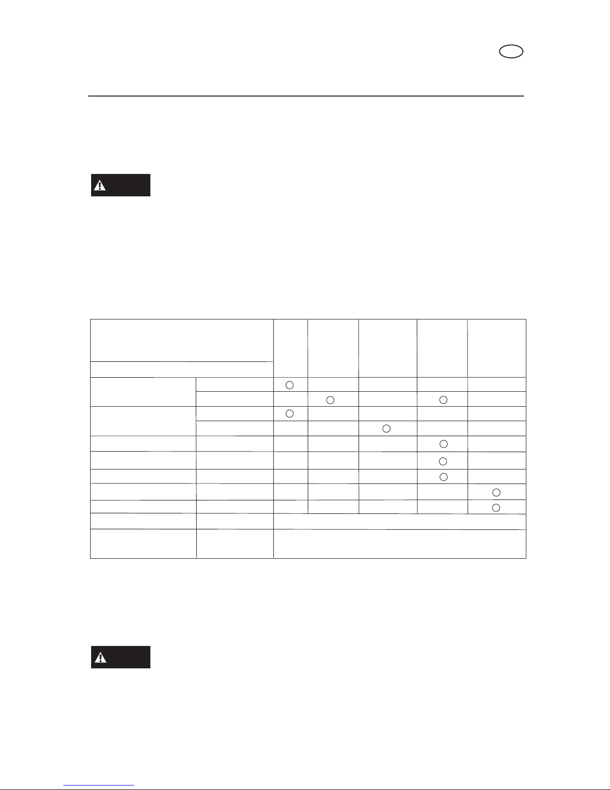
7. MANUTENZIONE
Una buona manutenzione è essenziale per un funzionamento sicuro, economico e senza
problemi. In questo modo si contribuisce anche a ridurre l’inquinamento dell’aria.
Il gas di scarico contiene particelle velenose di monossido di carbonio.
Spegnere il motore prima di effettuare qualsiasi intervento di
manutenzione. Se il motore deve restare acceso, assicurasi che l’area di operazione
sia ben ventilata.
La manutenzione e la regolazione periodiche sono necessarie per mantenere il generatore
in buone condizioni di funzionamento. Eseguire la manutenzione e i controlli con la
frequenza indicata nella tabella di seguito.
1) TABELLA DI MANUTENZIONE
(1) Provvedere alla manutenzione con più frequenza se la macchina viene usata in zone con polvere.
(2) Questi componenti devono essere sottoposti a manutenzione presso un rivenditore autorizzato di
generatori, salvo se il proprietario sia in possesso degli strumenti adatti e abbia competenze in ambito
meccanico.
(3) Per un uso commerciale professionale, registrare le ore di funzionamento per determinare i giusti
intervalli di manutenzione.
Se si esegue una manutenzione impropria o non si corregge un problema
prima di avviare il generatore, si possono causare malfunzionamenti
con rischio di gravi lesioni o di morte.
Seguire sempre quanto consigliato per il controllo e la manutenzione e la frequenza
di queste operazioni, così come riportato nel Manuale d’uso.
PERIODO DI MANUTENZIONE REGOLARE
Da effettuare con la frequenza mensile od oraria
indicata, quella tra le due che viene prima.
VOCE
Olio motore
Filtro dell’aria
Vasca di Sedimentazione
Candela
Parascintille
Gioco valvola
Serbatoio e filtro carburante
Testa del cilindro
Tubo del carburante
Controlare livello
Cambiare
Controllare
Pulire
Pulire
Pulire
Controllare-Pulire
Controllare-regolare
Pulire
Pulire
Controlare
(sostituire se
necessario)
A
ogni
uso
Il primo
mese o
dopo
20 ore(3)
Ogni 3 mesi
o
50 ore (3)
Ogni 6 mesi
o
100 ore
(3)
Ogni anno
o
300 ore
(3)
(1)
(2)
(2)
Ogni 300 ore (2)
Ogni 2 anni (2)
MANUTENZIONE
AVVISO
AVVISO
I
57

Le frequenze con cui eseguire gli interventi di manutenzione fanno riferimento a condizioni
di uso normali. Se il generatore funziona in condizioni più rigide, con carichi pesanti o
ad alte temperature per esempio, oppure in ambienti umidi o polverosi, rivolgersi al
rivenditore che effettua la manutenzione per avere consigli specifici in base alle esigenze
e agli usi personali.
2) Kit di attrezzi
Gli attrezzi in dotazione con il generatore aiutano a eseguire gli interventi di manutenzione
e le procedure realizzabili dall’utente e descritte nelle pagine seguenti. Conservare sempre
questo kit di attrezzi insieme al generatore.
3) Cambio dell’olio del motore
Far defluire l’olio con il motore caldo per eliminarlo completamente e rapidamente.
1 Togliere il tappo di scarico e la guarnizione sigillante, il tappo del serbatoio, e far uscire
l’olio.
2 Rimettere il tappo di scarico e la guarnizione sigillante. Serrare il tappo con forza.
3 Riempire con l’olio consigliato (vedi pag. 53) e controllare il livello.
MANUTENZIONE
PRESA AC
CACCIAVITE
SACCA PER ATTREZZI
CHIAVE PER TRASPORTO
MANUBRIO
TAPPO DI SCARICO
DELL’OLIO
TAPPO DEL SERBATOIO
DELL’OLIO
LIVELLO SUPERIORE
I
58

Capacità del serbatoio dell’olio:
LC 1800 DC: 0,6 litri
LC 2500 DC: 0,6 LITRI
LC 3800 DDC - LC 5000 DDC - LC 6500 DDC: 1,1 litri
L’olio per motore esausto può causare cancro alla pelle se lasciato
ripetutamente a contatto con l’epidermide per periodi prolungati. Sebbene
sia difficile che si tocchi l’olio quotidianamente, è comunque consigliabile lavare
accuratamente le mani con sapone e acqua non appena possibile dopo aver toccato
olio esausto.
Smaltire l’olio esausto per motore in modo compatibile con l’ambiente. Consigliamo di
metterlo in un contenitore sigillato e portarlo alla stazione di servizio al centro di riciclaggio
per il recupero. Non gettarlo nella spazzatura, non versarlo a terra.
4) Manutenzione del filtro dell’aria
Un filtro dell’aria sporco limiterà il flusso d’aria al carburatore. Per evitare un malfunzionamento
di quest’ultimo, eseguire interventi di manutenzione al filtro a intervalli regolari. Aumentare
la frequenza se il generatore funziona in aree estremamente polverose.
L’uso di benzina o solventi infiammabili per pulire il filtro può generare
incendio o esplosione. Usare solo acqua saponata o solventi non
infiammabili.
Non usare il generatore senza filtro dell’aria. Ne deriverebbe un rapido
consumo del motore.
1 Sganciare le grappe del coperchio del filtro,
togliere il coperchio e rimuovere il filtro.
2 Lavare il filtro in una soluzione di detergente per uso
domestico e acqua calda, poi asciugare con cura.
Oppure lavare con un solvente non infiammabile o con
un punto di infiammabilità elevato.
Lasciare asciugare il filtro completamente.
3 Immergere il filtro nell’olio per motore pulito e strizzarne l’eccesso. Il motore produrrà del
fumo al momento dell’avvio iniziale se viene lasciato troppo olio nel filtro.
MANUTENZIONE
CLIP
FILTRO DELL’ARIA
ATTENZIONE
NOTA
AVVISO
I
59

Reinstallare il filtro dell’aria e il coperchio.
5) Pulizia della vasca di sedimentazione
del carburante
La vasca di sedimentazione serve per evitare
che lo sporco o l’acqua, eventualmente presenti
nel serbatoio del carburante, arrivino al carburatore.
Se il motore è rimasto inattivo per un periodo
prolungato, la vasca di sedimentazione
deve essere pulita.
1 Spostare la valvola del carburante
in posizione OFF.
2 Togliere la vasca di sedimentazione,
e l’anello a O.
3 Pulire la vasca di sedimentazione,
e l’anello a O, con solvente non infiammabile
o con un punto di infiammabilità elevato
4 Reinserire l’anello a O e la vasca di sedimentazione
6) Manutenzione delle candele
Candele consigliate: F7RTC o equivalenti
Per garantire un funzionamento corretto, la candela deve avere i giusti interstizi e deve
essere priva di depositi.
Quando il motore è acceso, la marmitta si scalda. Fare attenzione a non toccare la
marmitta dopo che il motore è stato in funzione.
1 Togliere il tappo della candela.
2 Eliminare eventuali tracce di sporco intorno alla base della candela.
MANUTENZIONE
FILTRO DELL’ARIA
FILTRO
VALVOLA DEL CARBURANTE
VASCA DI
SEDIMENTAZIONE
FILTRO DEL
CARBURANTE
ANELLO A O
VASCA DI
SEDIMENTAZIONE
I
60

Usare la chiave in dotazione con il kit degli attrezzi per togliere la candela.
Controllare visivamente la candela. Eliminarla se l’isolatore è incrinato o scagliato.
Pulire la candela con una spazzola metallica se deve essere riutilizzata.
Misurare l’interstizio della candela con uno spessimetro.
Correggere se necessario piegando con attenzione
il lato dell’elettrodo.
La distanza deve essere di 0,70-0,80 mm.
Controllare che la guarnizione della candela sia in buone condizioni, e infilare la
candela manualmente per evitare incroci.
Una volta che la candela è alloggiata nella propria sede, serrarla con l’apposita chiave
per comprimere la guarnizione.
Se si installa una nuova candela, dopo averla alloggiata nella sede serrare con mezzo
giro per comprimere la guarnizione. Se si reinserisce una candela usata, dopo averla
alloggiata nella sede serrare con un giro di 1/8 – 1/4 per comprimere la guarnizione.
La candela deve essere serrata saldamente. Una candela lenta può
diventare rovente e danneggiare il motore. Non usare mai le candele
con un campo di variazione di calore non idoneo. Usare solo le candele consigliate
o equivalenti.
MANUTENZIONE
NOTA
CHIAVE PER LA CANDELA
TAPPO DELLA CANDELA
0,70-0,80 mm
I
61
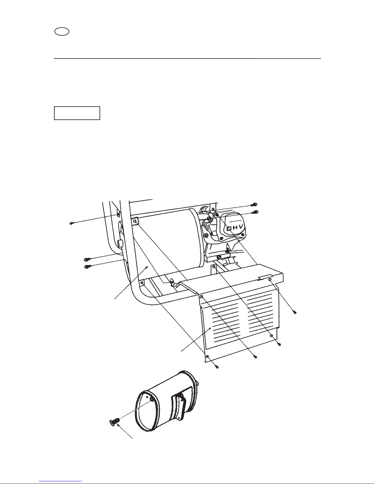
7). Manutenzione del parascintille
Se il generatore è stato in funzione, la marmitta diventa molto calda. Fatela freddare
prima di procedere.
Il parascintille deve essere sottoposto a manutenzione ogni 100
ore per mantenere la propria efficienza.
LC 1800 DC - LC 2500 DC:
Allentare i cinque bulloni da 6 mm per togliere la protezione della marmitta.
Togliere i due bulloni da 8 mm sul tubo di scarico e i due bulloni da 8 mm sul tirante
della marmitta.
Togliere la marmitta e il parascintille.
MANUTENZIONE
NOTA
BULLONE
DA 6 mm
BULLONE DA
8mm
MARMITTA
PROTEZIONE DELLA
MARMITTA
BULLONE DA 6mm
BULLONE DA
8mm
PARASCINTILLE
I
62

LC 3800 DDC - LC 5000 DDC - LC 6500 DDC:
Usare una spazzola per eliminare i depositi di combustione dallo schermo del parascintille.
Controllare lo schermo del parascintille per verificare la presenza di fori o segni di usura.
Sostituire se necessario.
Controllare il tubo di scarico e sostituirlo se necessario. Reinstallare la marmitta e la
protezione.
MANUTENZIONE
PARASCINTILLE
I
63

8. TRASPORTO/CUSTODIA
Quando si trasporta un generatore, spostare l’interruttore del motore e la valvola del
carburante in posizione OFF. Tenere il generatore in piano per evitare fuoriuscite di
carburante. I vapori o le fuoriuscite di carburante possono prendere fuoco.
Il contatto con il motore caldo o il sistema di scarico può causare gravi
ustioni o incendi. Lasciare che il motore si raffreddi prima di trasportarlo
o riporlo.
Fare attenzione a non lasciar cadere o urtare il generatore durante il trasporto.
Non collocare oggetti pesanti sul generatore.
Prima di riporre l’unità per un periodo di tempo prolungato:
assicurarsi che l’area di custodia sia priva di eccessiva umidità e polvere.
Provvedere alla manutenzione secondo quanto indicato nella tabella di seguito:
TRASPORTO/CUSTODIA
TEMPO DI CUSTODIA PROCEDURA DI MANUTENZIONE CONSIGLIATA
PER EVITARE PROBLEMI ALL’ACCENSIONE
Meno di un mese
da 1 a 2 mesi
da 2 mesi ad 1 anno
1 anno o più
*Usare additivi per benzina formulati appositamente per allungarne la conservazione.
Contattare il proprio rivenditore autorizzato di generatori per farsi consigliare l’additivo più adatto.
Non è necessaria nessuna preparazione
Riempire con benzina nuova e aggiungere additivo*
Riempire con benzina nuova e aggiungere additivo *
Svuotare la vaschetta del carburatore (pag.66).
Svuotare la vasca di sedimentazione del carburante (pag. 60).
Riempire con benzina nuova e aggiungere additivo *
Svuotare la vaschetta del carburatore (pag. 66).
Svuotare la vasca di sedimentazione del carburante (pag. 60).
Togliere la candela. Mettere un cucchiaio di olio per motore nel cilindro.
Girare lentamente il motore per distribuire l’olio.
Reinstallare la candela.
Cambiare l’olio del motore (pag. 58).
Quando si riutilizza il generatore, prima di riavviarlo,
togliere la benzina rimasta e svuotarla in un contenitore apposito,
e riempire il serbatoio con benzina nuova.
AVVISO
I
64

1 Svuotare il carburatore allentando la vite di scolo, e far defluire la benzina in un
contenitore apposito.
La benzina è un materiale estremamente infiammabile e in certe
condizioni è esplosiva. Effettuare questa operazione in un’area ben
ventilata con il motore spento. Non fumare o generare fiamme o scintille nell’area
in cui si sta effettuando l’operazione.
2 Cambiare l’olio del motore.
3 Togliere la candela, e versare un cucchiaio di olio per motore pulito nel cilindro. Ruotare
il motore diverse volte per far distribuire l’olio, poi reinserire la candela.
4 Tirare lentamente la maniglia del dispositivo di avvio finché non si incontra resistenza.
A questo punto il pistone sale per spinta e si chiudono sia la valvola di aspirazione
sia quella di scarico. Riporre il motore in questa posizione aiuterà a proteggerlo dalla
corrosione interna.
TRASPORTO/CUSTODIA
VITE DI SCOLO
AVVISO
I
65

9. INDIVIDUAZIONE ED ELIMINAZIONE DI GUASTI
Quando il motore non parte
Non c’è elettricità nelle prese di corrente AC:
INDIVIDUAZIONE ED ELIMINAZIONE DI GUASTI
NO
NO
NO
NO
NO
SI
SI
SI
SI
C’è il carburante
nel serbatoio?
Riempire il serbatoio
C’è olio a sufficienza
nel motore
Aggiungere olio del tipo
consigliato
La candela fa la
scintilla?
Sostituire
la candela
Portare il generatore
presso un
rivenditore autorizzato
Il carburante arriva
al carburatore?
Pulire la vasca
di sedimentazione
Se il motore no parte ancora, portare il
generatore presso un rivenditore autorizzato
NO
SI
NO
SI
L’interruttore salvavita è in
posizione ON?
Spostare l’interrutore AC
in posizione ON
Controllare l’apparecchio o
l’impianto elettrico per eventuali
guasti
Portare il generatore presso
un rivenditore autorizzato
- Sostituire l’apparecchio o l’impianto elettrico
- Portare l’apparecchio o l’impianto elettrico presso
un elettricista per farlo riparare.
I
Ancora
scintille
66

SCHEMA DEL CABLAGGIO
10. SCHEMA DEL CABLAGGIO
Bianco
Verde
Rosso
Blu
Marrone
Nero
Giallo
Verde chiaro
B
V
R
B
M
N
G
Vc
M
N
N
G
G
N
N
N
NG
N/B
N/B
B
B
G/V
G/V
B
M
G
B
M
B
G
G
V
V
R
B
B
RR
B
B
R
G/V
BOBINA
DI
CARICA
BATTERIA MOTORINO DI
AVVIAMENTO
INTERRUTTORE DEL
LIVELLO DELL'OLIO
SPIA
DELL'OLIO
CANDELA BOBINA DI
ACCENSIONE
SEZIONE DEL MOTORE
SEZIONE DEL PANNELLO DI CONTROLLO
SERPENTINA DC
SERPENTINA
DELL'ECCITATORE
SERPENTINA
DI CAMPO
SEZIONE GENERATORE
SERPENTINA
PRINCIPALE
VOLTIMETRO
INTERRUTTORE SALVAVITA
DIODO DC
PROTETTORE DC
MORSETTO DC
FUSIBILE(5A 250V)
INTERRUTTORE A COMBINAZIONE
PRESA DI CORRENTE AC
MORSETTO
MESSA A TERRA
INTERRUTTORE A COMBINAZIONE
START
E
BAT
ST
IG
AVR
30A 250V 30A 250V
ON
OFF
IG
E
ST BAT
V
I
67

SCHEMA DI CABLAGGIO
Bianco
Verde
Rosso
Blu
Marrone
Nero
Giallo
Verde chiaro
B
V
R
B
M
N
G
Vc
V/B V/B
G
N
G
N
G/V
R
B
M
M
V
M
M
R
G/V
M
M
N
G
B
V/B
B
N/B
N
G/V
B
V/B
B
N/B
B
V
B
B
B
Vc
R
B
AVR
B
M
B
M
B
SEZIONE DEL MOTORE
SEZIONE DEL PANNELLO DI CONTROLLO
SERPENTINA DC
SERPENTINA
DELL'ECCITATORE
SEZIONE DEL GENERATORE
SERPENTINA
PRINCIPALE
VOLTIMETRO
INTERRUTTORE SALVAVITA
DIODO DC
PROTETTORE DC
MORSETTO DC
INTERRUTTORE A COMBINAZIONE
PRESA DI CORRENTE AC
MORSETTO
DI MESSA A TERRA
INTERRUTTORE A COMBINAZIONE
START
FUSIBILE (5A 250V)
VALVOLA
SOLENOIDE
DI
FUORIUSCITA
DEL
CARBURANTE
SERPENTINA DI
ARRESTO
DEL CARBURANTE
SERPENTINA
DI CAMPO
BOBINA
DI
CARICA
BATTERIA
MOTORINO DI
AVVIAMENTO
INTERRUTTORE DEL
LIVELLO DELL'OLIO
SPIA
DELL'OLIO
CANDELA BOBINA DI
ACCENSIONE
30A 250V 30A 250V 30A 250V
ON
OFF
IG E FS G ST BAT
V
E
FS
BAT
ST
G
IG
I
68

SCHEMI DI CABLAGGIO
Bianco
Verde
Rosso
Blu
Marrone
Nero
Giallo
Verde chiaro
B
V
R
B
M
N
G
Vc
M
N
Y
G
G
G/V
G/V
G
N
N
N
G/V
B
B
V/B
V/B
B
B
N/B
N/B
N
N
M
V/BV/B
M
M
R
V
G
B
R
B
B
NN
G
GVV
R
R
RB
SEZIONE DEL PANNELLO DI CONTROLLO
SEZIONE DEL GENERATORE
INTERRUTTORE SALVAVITA
VOLTIMETRO
PRESA DI CORRENTE AC
MORSETTO DELLE PRESE DI CORRENTE AC
MORSETTO
DI MESSA
A TERRA
INTERRUTTORE A COMBINAZIONE
INTERRUTTORE A COMBINAZIONE
SERPENTINA
DELL'ECCITATORE
SERPENTINA DI
ARRESTO
DEL CARBURANTE
SERPENTINA
DI CAMPO
SEZIONE DEL MOTORE
START
VALVOLA
SOLENOIDE
DI
FUORIUSCITA
DEL
CARBURANTE
BOBINA
DI
CARICA
BATTERIA MOTORINO DI
AVVIAMENTO
INTERRUTTORE DEL
LIVELLO DELL'OLIO
SPIA
DELL'OLIO
CANDELA
BOBINA DI
ACCENSIONE
V
FUSE (5A 250V)
ON
OFF
IG E FS G ST BAT
E
FS
BAT
ST
G
IG
U
V
W
O
A V R
MW U
MW V
MW W
I
69

11. SPECIFICHE
Note: disponibile; - non disponibile
NB: Le specifiche sono soggette a modifiche senza preavviso.
SPECIFICHE
Voce
Tipo di motore
Caratteristiche motore
Cilindrata (cc)
Modalità di accensione
Volume del carburante
Consumo del carburante (L/h)
Tempo continuativo (h)
Volume dell'olio (L)
Voltaggio di carica (V)
Corrente di carica (A)
Frequenza stabilita (Hz)
Voltaggio stabilito (V)
Energia prodotta stabilita (kW)
Energia prodotta massima (kW)
Lunghezza (mm)
Larghezza (mm)
Altezza (mm)
Peso Netto (kg)
Fase
Filtro dell'aria grande
Marmitta grande
Serbatoio carburante grande
Indicatore livello carburante
Voltimetro
Regolatore automatico
di voltaggio
Sistema di controllo dell'olio
Interruttore senza fusibili
Portabatteria
Motore
Generatore
Gruppo
generatore
Accessori
comuni
Cilindro singolo, 4 tempi, raffredamento forzato ad aria, OHV
Magnete Transistorizzato
Singola
Singola
Singola
Singola
Singola
Singola
Singola
Singola
Singola
I
70

Note: disponibile; - non disponibile
NB: Le specifiche sono soggette a modifiche senza preavviso.
SPECIFICHE
Singola Singola Singola Singola Singola Singola
Singola / trifase
Cilindro singolo, 4 tempi, raffredamento forzato ad aria, OHV
Magnete Transistorizzato
Motore
Generatore
Gruppo
generatore
Accessori
comuni
Voce
Tipo di motore
Caratteristiche motore
Cilindrata (cc)
Modalità di accensione
Volume del carburante
Consumo del carburante (L/h)
Tempo continuativo (h)
Volume dell'olio (L)
Voltaggio di carica (V)
Corrente di carica (A)
Frequenza stabilita (Hz)
Voltaggio stabilito (V)
Energia prodotta stabilita (kW)
Energia prodotta massima (kW)
Lunghezza (mm)
Larghezza (mm)
Altezza (mm)
Peso Netto (kg)
Fase
Filtro dell'aria grande
Marmitta grande
Serbatoio carburante grande
Indicatore livello carburante
Voltimetro
Regolatore automatico
di voltaggio
Sistema di controllo dell'olio
Interruttore senza fusibili
Portabatteria
I
71

12 . COMPONENTI FACOLTATIVI
(LC 3800 DDC - LC 5000 DDC - LC 6500 DDC)
BATTERIA
Usare una batteria a 12 V, 28AH o maggiore.
Non invertite la polarità.
Potrebbero verificarsi seri danni
al generatore e/o alla batteria.
Se non si segue una procedura corretta la batteria può esplodere,
causando serie ferite alle persone vicine. Tenere lontani dalla batteria
scintille, fiamme libere e materiali fumanti.
Controllare il livello dell’elettrolito per essere sicuri che sia compreso tra i segni della
scatola. Se il livello si trova al di sotto del segno inferiore, togliere i tappi e aggiungere
acqua distillata per portare il livello dell’elettrolito al segno superiore. Le pile devono
rimanere ugualmente piene.
Kit del vassoio della batteria
1 Installare la protezione della batteria sul telaio.
Collocare il vassoio della batteria sulla relativa protezione e serrare i bulloni.
2 Far passare il cavo del motorino di avviamento sotto al serbatoio e collegarlo al
solenoide del motorino di avviamento.
COMPONENTI FACOLTATIVI
NOTA
PROTEZIONE
DELLA BATTERIA
CAVO
DI MESSA
A TERRA
STAFFA
DELLA
BATTERIA
PIASTRA
DI PROTEZIONE DELLA BATTERIA
VASSOIO
DELLA BATTERIA
PROTEZIONE
DELLA
BATTERIA
CAVO
DEL MOTORINO
DI AVVIAMENTO
SOLENOIDE DEL MOTORINO
DI AVVIAMENTO
LIVELLO SUPERIORE
LIVELLO INFERIORE
I
AVVISO
72
CAVO DEL MOTORINO
DI AVVIAMENTO (positivo)

1 Collegare il cavo di messa a terra all’alloggiamento posteriore del generatore.
2 Collocare la batteria sull’apposito vassoio e fissarla tramite la staffa.
Collegare prima il cavo del motorino di avviamento al morsetto positivo (+) della
batteria, poi collegare il cavo di messa a terra al morsetto negativo (-). Per disconnettere,
scollegare prima il morsetto negativo (-) della batteria.
3 Installare la piastra di protezione della batteria sulla protezione della stessa.
COMPONENTI FACOLTATIVI
I
73

Informazioni sullo smaltimento delle apparecchiature elettriche ed elettroniche in ottemperanza alla direttiva
2002/96 CE (RAEE).
Attenzione: per smaltire il presente prodotto non utilizzare il normale bidone della spazzatura.
Le apparecchiature elettriche ed elettroniche usate devono essere gestite a parte ed in conformità alla legislazione
che richiede il trattamento, il recupero e il riciclaggio adeguato dei suddetti prodotti.
In seguito alle disposizione attuate dagli Stati membri, i privati residenti nella UE possono conferire gratuitamente
le apparecchiature elettriche ed elettroniche usate a centri di raccolta designati.
In caso di difficoltà nel reperire il centro di raccolta autorizzato allo smaltimento, interpellare il rivenditore dal quale
è stato acquistato il prodotto.
La normativa nazionale prevede sanzioni a carico dei soggetti che effettuano lo smaltimento abusivo o l’abbandono
dei rifiuti di apparecchiature elettriche ed elettroniche.
Information on the disposal of electric and electronic equipment in compliance with directive 2002/96 CE (RAEE).
Warning: do not use the normal house trash bin to dispose of this product.
Used electric and electronic equipment must be handled separately and in compliance with the regulations relating to the treatment,
recovery and recycling of the said products.
In accordance with the regulations applied in the member States, private users resident in the EU can take used electric and electronic
equipment free of charge to designated collection centers.
If you experience difficulties in locating an authorized disposal center, consult the dealer from whom you purchased the product.
The national regulations provide sanctions against whoever unlawfully disposes of or abandons waste of electric or electronic equipment.
Informations sur l’élimination des appareillages électriques et électroniques en conformité avec la directive 2002/96 CE (RAEE).
Attention: pour éliminer ce produit, ne pas utiliser la poubelle ordinaire.
Les appareillages électriques et électroniques usagés doivent être gérés séparément et en conformité avec la législation régissant le
traitement, la récuparation et le recyclage de ces produits.
Suite aux dispositions en vigueur dans les États membres, les particuliers résidant en UE peuvent porter gartuitement les appareillages
électriques et électroniques usagés aux centres de récolte désignés.
En cas de difficultés pour trouver le centre de récolte autorisé à l’élimination, veuillez interpeller le revendeur qui vous a vendu l’appareil.
La législation nationale prévoit des sanctions à la charge des sujets qui abandonnet ou éliminent les déchets d’appareillages électriques
ou électroniques de façon illégale.
SPAÑOL
Informaciones sobre el desguace de aparatos eléctricos y electrónicos en conformidad con la directiva 2002/96 CE (RAEE).
Atención: no utilizar la normal lata de la basura para desguazar el presente producto.
Los aparatos eléctricos y electrónicos necesitan un manejamiento saparado en conformidad con la legislación que require el tratamiento,
la recuperación y el reciclaje de los dichos productos.
En conformidad con las disposiciones vigentes en los Estados miembros, los particulares residentes en la UE pueden llevar gratuitamente
los aparatos eléctricos y electrónicos de uso a centrales de recolección designadas. En caso de dificultades para localizar la central de
recolección autorizada para el desguace, sirvanse consultar el rivendidor donde el producto fué comprado.
La normativa nacional preve sanciones a cargo de sujetos que abandonan ó desguazan los desechos de aparatos eléctricos ó eléctronicos
en forma abusiva.
Informationen zur Entsorgung von Elektrogeräten sowie elektronischen Geräten gemäß Richtlinie 2002/96 CE (RAEE).
Hinweis: verwenden Sie nicht den normalen Hausabfall, um dieses Produkt zu beseitigen.
Gebrauchte Elektrogeräte sowie elektronische Geräte müssen separat, gemäß der Gesetzgebung, welche die sachgemäße Behandlung,
Verwertung und das Recycling dieser Produkte vorschreibt, verwertet werden.
Gemäß aktueller Anordnungen der Mitgliedsstaaten können private Haushalter der EU die gebrauchten Elektrogeräte sowie elektronische
Geräte kostenlos zu den dafür vorgesehen Müllverwertungszentren bringen.
Die nationalen Anordnungen sehen Sanktionen gegen diejenigen vor, die Abfälle von elektrischen oder elektronischen Geräten rechtswidrig
entsorgen oder verlassen.
Informações a respeito da eliminação de aparelhos eléctricos e electrónicos conforme disposto na directiva 2002/96 CE (RAEE).
Atenção: não elimine este produto deitando-o nos recipientes de lixo normais.
Os aparelhos eléctricos e electrónicos devem ser tratados em separado e segundo a legislação que prevê a recuperação, a reciclagem
e tratamento adequados de tais produtos.
Segundo as disposições actuadas pelos Estados-membros, os utilizadores domésticos que residam na União Europeia podem entregar
gratuitamente os aparelhos eléctricos e electrónicos usados em centros de recolha autorizados.
Se for difícil localizar um centro de recolha autorizado para a eliminação, contactar o revendedor onde se comprou o produto.
A legislação nacional prevê sanções para aqueles que efectuam a eliminação abusiva de resíduos de aparelhos eléctricos e electrónicos
ou os abandonam no meio ambiente.

Informatie over het milieuvriendelijk afvoeren van elektronische installatie volgens richtlijn 2002/96 CE (RAEE)
Opgepast: product niet meegeven met normaal huisvuil ophaling.
Gebruikte elektrische en elektronische apparaten moeten apart worden verwerkt volgens de wet van het de verwerking,
hergebruiking en recyclage van het product.
Overeenkomstig de regeringen die in de lidstaten worden toegepast, de privé gebruikers wonende in de EU kunnen
gebruikte elektrische en elektronisch kosteloos inleveren in aangewezen inzamelingscentra.
Als u moeilijkheden ondervindt met het vinden van een inzamelingscentrum, neem dan contact op met de dealer
waar u het product heeft aangekocht. De nationale regeringen verstrekken sancties tegen personen die afval van
elektrisch of elektronisch materiaal wegdoen of onwettig achterlaten.
Information om deponering av avfall som utgörs av eller innehåller elektriska och elektroniska produkter i enlighet med direktiv
2002/96 CE (WEEE).
Observera! Släng inte denna produkt i den vanliga soptunnan
som utgörs av eller innehåller elektriska och elektroniska måste hanteras separat och i enlighet med lagstiftningen som kräver behandling,
återvinning och återanvändning av sådana produkter.
I enlighet med bestämmelserna som antagits av medlemsstaterna får privatpersoner som är bosatta inom EU kostnadsfritt lämna in
uttjänta elektriska och elektroniska produkter till speciella uppsamlingsställen.
Om du har svårighet att hitta en uppsamlingsplats som är auktoriserad för deponering, vänd dig till distributören där du har köpt
produkten.
Den nationella lagstiftningen omfattar sanktioner för den som på olagligt sätt deponerar eller överger avfall bestående av elektriska och
elektroniska produkter.
Informationer om bortskaffelse af elektrisk og elektronisk udstyr i overensstemmelse med direktiv 2002/96/EF (WEEE).
Advarsel: brug ikke den normale affaldsbeholder til bortskaffelse af dette produkt.
Brugt elektrisk og elektronisk udstyr skal behandles separat i henhold til lovgivningen, der kræver passende behandling, genvinding og
genbrug af disse produkter.
I henhold til bestemmelserne, der er iværksat af EU-landene, kan privatpersoner, der er bosat her, gratis aflevere brugt elektrisk og
elektronisk udstyr til udvalgte indsamlingscentre.
Hvis det er vanskeligt at finde et opsamlingscenter, der har tilladelse til bortskaffelse, bedes De kontakte forhandleren, hvor produktet
er købt. Det nationale normativ forskriver sanktioner for dem, der foretager ulovlig bortskaffelse eller efterladelse af elektrisk og elektronisk
udstyr.
Tietoja sähköisten ja elektronisten laitteiden hävittämisestä direktiivin 2002/96/EY (WEEE) mukaisesti.
Huomio: Tätä tuotetta ei saa heittää tavalliseen jätesäiliöön
Käytetyt sähköiset ja elektroniset laitteet täytyy hävittää erikseen ja se on tehtävä näiden tuotteiden käsittelyä, talteenottoa ja kierrätystä
koskevien lakien mukaisesti.
Mikäli hävittämiseen valtuutettua keräyskeskusta on vaikea löytää, kysy asiaa jälleenmyyjältä, jolta tuote on ostettu.
Kansalliset asetukset määräävät rangaistuksen henkilöille, jotka hävittävät sähköiset ja elektroniset laitteet väärin tai jättävät ne heitteille.
Informasjon om avhending av elektriske og elektroniske apparater i henhold til direktivet 2002/96 CE (RAEE).
Advarsel: dette produktet skal ikke kastes sammen med det vanlige avfallet
Utbrukte elektriske og elektroniske apparater skal tas hånd om på annen måte og i samsvar med loven, som krever korrekt behandling,
gjenvinning og resirkulering av slike produkter.
I henhold til bestemmelsene i medlemslandene, kan private som er bosatte i EU gratis innlevere de brukte elektriske og elektroniske
apparatene til bestemte innsamlingssentre.
Dersom du har problemer med å finne et autorisert innsamlingssenter, bør du kontakte forhandleren der du kjøpte produktet.
Loven straffer den som ikke tar hånd om avfall på korrekt vis eller etterlater elektriske og elektroniske apparater i miljøet.
Пληροφορες για τη διθεση του ηλεκτρικοÚ και ηλεκτρονικοÚ εξο∏λισμοÚ σÚμφωνα με την οδηγα 2002/96/ΕΚ
(ΑΗΕΕ).
Пροσοχ: για τη διθεση αυτο
Ú του προϊντος μη χρησιμοποιετε τους κοινοÚς κδους απορριμμτων
Οι ηλεκτρικ"ς και ηλεκτρονικ"ς συσκευ"ς πρ"πει να διατθενται χωριστ και σ‡μφωνα με την ισχ‡ουσα νομοθεσα
που απαιτε την επεξεργασα, την ανκτηση και την ανακ‡κλωση των προϊντων αυτ#ν.
Μετ την εφαρμογ των διατξεων απ τα κρτη μ"λη, οι ιδι#τες που κατοικο
Úν στην Ευρωπαϊκ %νωση μποροÚν
να παραδδουν δωρεν τις ηλεκτρικ"ς και ηλεκτρονικ"ς συσκευ"ς σε εξουσιοδοτημ"να κ"ντρα συλλογς *.
Σε περπτωση που δυσκολε
Úσετε να εντοπσετε το εξουσιοδοτημ"νο κ"ντρο συλλογς, απευθυνθετε στο κατστημα
απ το οποο αγορσατε το προϊν.
Η εθνικ νομοθεσα προβλ"πει κυρ#σεις για τους υπε
Úθυνους της παρνομης διθεσης της εγκατλει
Ψ
ης των
απορριμμτων ηλεκτρικο
Ú και ηλεκτρονικοÚ εξοπλισμοÚ.
FIN

DICHIARAZIONE DI CONFORMITÀ
EC declaration of conformity
We declare that articles present in this handbook comply
with the following Directives:
y 2006/42/CE
y 2006/95/CE
y 2004/108/CE
GB
I
Applied harmonized standards:
•EN 60034-1/EN 60335-1/EN 60335-2-41
EN 292-1/EN292-2/EN 55014/EN ISO 3744
Dichiarazione CE di conformità
Si dichiara che gli articoli del presente libretto sono conformi
alle seguenti Direttive:
y 2006/42/CE
y 2006/95/CE
y 2004/108/CE
Norme armonizzate applicate:
•EN 60034-1/EN 60335-1/EN 60335-2-41
EN 292-1/EN292-2/EN 55014/EN ISO 3744
COD. 7108978 - REV. 2 - 02/2009
y 2001/63/CE
y 2002/88/CE
y 2000/14/CE
y 2001/63/CE
y 2002/88/CE
y 2000/14/CE
 Loading...