

Sperian Panther Hip-Pac P9684 Series, Panther Hip-Pac P9686 Series, Panther Hip-Pac P9685 Series, Panther Hip-Pac 9649 Operation Manual
Page 1
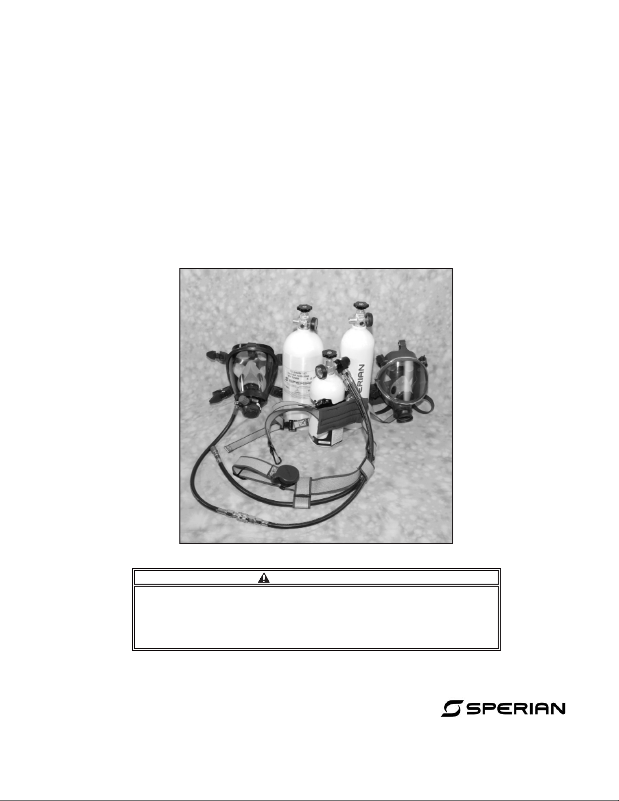
PANTHER HIP-PAC
™
SUPPLIED-AIR RESPIRATOR, PRESSURE-DEMAND CLASS
AND
SELF-CONTAINED BREATHING APPARATUS
P9684 SERIES 5- and 10-Minute Escape
P9685 SERIES 15-Minute Escape
P9686 SERIES HP 10-Minute Escape
9649 SERIES HP 10-Minute Escape
OPERATION MANUAL
DO NOT USE this respirator until you completely read and understand this
instruction manual. You are required to inspect your respirator prior to put-
ting it into eld service. Please refer to the inspection procedures in this
manual. Failure to comply with this Warning may lead to serious personal
injury, serious illness, or death.
© Copyright SPERIAN May 2003
All Rights Reserved
P/N 963018 REV B 12/13
WARNING
AN ISO 9001
REGISTERED
COMPANY
Sperian Respiratory Protection USA, LLC
3001 South Susan St., Santa Ana, CA 92704
Toll Free (800) 873-5242
www.sperianprotection.com
Page 2

Page 3
Panther HIP-PAC
Table of Contents
I. INTRODUCTION. . . . . . . . . . . . . . . . . . . . . . . . . . . . . . . . 1
II. SAFETY PRECAUTIONS . . . . . . . . . . . . . . . . . . . . . . . . 1
III. DESCRIPTION . . . . . . . . . . . . . . . . . . . . . . . . . . . . . . . . 1
IV. PARTS LIST . . . . . . . . . . . . . . . . . . . . . . . . . . . . . . . . . . 4
V. USE INSTRUCTIONS . . . . . . . . . . . . . . . . . . . . . . . . . . . 6
A. Air Supply . . . . . . . . . . . . . . . . . . . . . . . . . . . . . . . . . . 6
B. Quick Coupler Assembly. . . . . . . . . . . . . . . . . . . . . . 6
C. Donning. . . . . . . . . . . . . . . . . . . . . . . . . . . . . . . . . . . . 7
D. Fit Check. . . . . . . . . . . . . . . . . . . . . . . . . . . . . . . . . . . 9
E. Emergency Exit. . . . . . . . . . . . . . . . . . . . . . . . . . . . . 11
F. Emergency Operation. . . . . . . . . . . . . . . . . . . . . . . . 11
G. Dofng. . . . . . . . . . . . . . . . . . . . . . . . . . . . . . . . . . . . 11
H. 21 Series Facepiece Drink Tube . . . . . . . . . . . . . . . 12
VI. MAINTENANCE . . . . . . . . . . . . . . . . . . . . . . . . . . . . . . 12
A. Conventional Facepiece Cleaning . . . . . . . . . . . . . 12
B. Hood-style Facepiece Cleaning . . . . . . . . . . . . . . . 13
C. Second Stage Regulator Cleaning . . . . . . . . . . . . . 14
D. Exterior Surfaces Cleaning . . . . . . . . . . . . . . . . . . . 14
E. Inspection . . . . . . . . . . . . . . . . . . . . . . . . . . . . . . . . . 14
F. Repair. . . . . . . . . . . . . . . . . . . . . . . . . . . . . . . . . . . . . 14
G. Functional Testing . . . . . . . . . . . . . . . . . . . . . . . . . . 14
H. Cylinder Maintenance and Recharging . . . . . . . . . 14
I. Cold Weather Operation and Maintenance . . . . . . . 17
J. Storage. . . . . . . . . . . . . . . . . . . . . . . . . . . . . . . . . . . . 19
K. Overhaul Frequency. . . . . . . . . . . . . . . . . . . . . . . . . 19
L. Additional Information . . . . . . . . . . . . . . . . . . . . . . . 19
VII. WARRANTY AND LIMITATION OF LIABILITY. . . . . . 20
VIII. INSPECTION TABLE . . . . . . . . . . . . . . . . . . . . . . . . . 21
IX. REPAIR TABLE . . . . . . . . . . . . . . . . . . . . . . . . . . . . . . 22
X. FUNCTIONAL TESTING TABLE . . . . . . . . . . . . . . . . . 23
XI. CAUTIONS AND LIMITATIONS. . . . . . . . . . . . . . . . . . 24
I. INTRODUCTION
This manual provides instructions for the use and maintenance of the SPERIAN Panther HIP-PAC™ pressuredemand supplied-air respirator and self-contained
breathing apparatus, P968450 Series, P968470 Series,
P968500 Series, P9686 Series, and 9649 Series. The
Panther HIP-PAC is intended for supplied-air entry into
hazardous atmospheres, and emergency exit using the
ve/ten/fteen-minute cylinder in the event of a remote
air supply failure. You must read and understand this
manual and be trained in the proper use of the Panther HIP-PAC before wearing it in a hazardous envi-
ronment.
II. SAFETY PRECAUTIONS
The Warnings, Cautions, and Notes contained in this
manual have the following signicance:
WARNING
Maintenance or operating procedures
and techniques that may result in serious personal injury, serious illness, or
death if not carefully followed.
CAUTION
Maintenance or operating procedures
and techniques that may result in damage to equipment if not carefully followed.
NOTE
Maintenance or operating procedures
and techniques or information considered
important enough to emphasize.
III. DESCRIPTION
The SPERIAN Panther HIP-PAC consists of a rellable
cylinder, valve and pressure gauge assembly, rst stage
regulator, second stage regulator, facepiece, waist belt,
and regulator hose. The cylinder stores 8 cubic feet of
air at 2216 psig for the 5-minute apparatus, 15.2 cubic
feet of air at 3000 psig for the 10-minute apparatus, 17
cubic feet of air at 4500 psig for the 10-minute apparatus, and 24 cubic feet of air at 3000 psig for the 15-minute apparatus. The cylinder valve controls air pressure
to the regulator, and houses a safety relief device and
a cylinder pressure gauge. The regulators reduce the
cylinder pressure or remote air pressure and supply a
ow to the facepiece. A check valve in the low pressure
air line hose prevents inward leakage of contaminated
air when disconnected from the air supply.
WARNING
• The employer is responsible for establishing that these respirators are suit-
able for the user’s application.
• No respirator can provide complete
protection from all conditions. Use
extreme care for all emergency opera-
tions. Do not use the Panther HIP-PAC
for interior structural re ghting, abra-
sive blasting, or under water.
• The pressure within the Panther HIP-
PAC remains positive under most work-
ing conditions, but as with all respira-
tors, negative pressure excursions are
possible. Conditions when a respirator
can experience negative facepiece pres-
sures include, but are not limited to: 1)
the respirator is improperly worn, 2) the
respirator is not used in accordance
with the instructions, or 3) the respira-
tor is over-breathed during heavy work
rates. The HIP-PAC will provide reduced
protection when operated in a negative
pressure mode.
• Your SPERIAN respirator has been
constructed of materials selected for
their performance, safety, and durability. However, all materials have limita-
tions to exposure to extremes of heat
and cold or to the many chemicals in
use today, and could be degraded by
exposure beyond their limitations, cre-
ating conditions in which this SPERIAN
equipment would be dangerous to use.
• Before allowing anyone to enter a
hazardous environment while wear-
ing SPERIAN equipment, the employer
must conduct safe, scientic tests to
determine if the environment could ren-
der the equipment unsafe. Results of
1
Page 4

Panther HIP-PAC
WARNING─Continued
this testing should be well docu-
mented. Seek the help of a certified
safety professional or industrial hy-
gienist. DO NOT USE this equipment
if the user would be endangered in
any way through environmentally in-
duced degradation of the materials in
the apparatus.
• All persons using this SPERIAN respirator must be made aware of its limita-
tions. We cannot be responsible for any
damage to property, personal injury, or
death in which environmental exposure
is a contributing factor.
• SPERIAN cannot predict what will hap-
pen to this equipment in every potential
environment. Materials can be chemi-
cally attacked if exposed to the wrong
environment and may exhibit corrosion
or other forms of damage. Permeation
or penetration of gases, liquids, or par-
ticles through the materials could be
excessive. Extremes of temperature
might cause thermal degradation. Each
of these things, or a combination of
them, could create conditions in which
this SPERIAN equipment would be dangerous to use.
• This respirator must be used in conjunction with a written respirator pro-
gram meeting the requirements of the
OSHA Standard for Respiratory Protec-
tion 29 CFR 1910.134, available from the
U.S. Department of Labor, Occupational
Safety and Health Administration. The
program must include, but not be lim-
ited to, procedures for evaluating air
contaminants and selecting appropriate
respirators, procedures for proper use
of respirators, procedures for testing
the facepiece-to-face t of respirators,
procedures for cleaning, disinfecting,
inspecting, maintaining, and storing
respirators, procedures for determining
if workers are physically and medical-
ly capable of wearing respirators, and
procedures for training employees in
the use of respirators and in recognizing the hazards associated with con-
taminants in the workplace.
• The air supply must meet the guidelines of the Compressed Gas Associa-
tion (CGA) pamphlet G-7.1, Grade D Air,
as appropriate.
• DO not wear this respirator if a satisfactory t, as determined by a qualita-
tive or quantitative t test, cannot be
obtained. See ANSI Z88.2, latest edition,
and OSHA 1910.134. Beards and side-
burns will prevent good facepiece seal.
Do not use this respirator unless you
are clean shaven.
WARNING─Continued
• This respirator does not protect exposed areas of the body. Some contam-
inants can be absorbed directly through
the skin while others may irritate exposed areas. This respirator does not
provide protection from splash of hazardous liquids, ying objects, hazard-
ous rays, or harmful noise. Always wear
proper head, ear, and eye protection.
• This respirator is designed for use in
temperatures above -30°F.
• When using this respirator at temperatures of 0 to -30°F, the rst stage regu-
lator must be wrench tightened on the
cylinder valve, and anti-fog solution,
P/N 951015 or 951016, must be applied
to the inside of the facepiece lens.
• The Panther HIP-PAC has a rated ser-
vice time of 5, 10, or 15 minutes. Under
average conditions, you will have up to
5, 10, or 15 minutes in which to escape
from a toxic environment. Stress and
exertion may cause extra air consump-
tion and reduce the service time. Know
escape routes in advance and the time
required to travel them.
• Compressors, storage cylinders,
valves, regulators, ttings, and other
hardware must be large enough to de-
liver the air volume required by all us-
ers at peak demand.
• This respirator will reduce, but will
not eliminate the inhalation of con-
taminants. Some sensitive individuals
may experience health problems when
exposed to even minute amounts of
contaminants. This respirator will not
prevent health problems for those indi-
viduals.
• Do not modify this respirator in any
manner.
• This respirator must only be worn
and used as specied in SPERIAN’s in-
structions. Always read and follow the
instructions listed in the Material Safe-
ty Data Sheet for the chemicals that are
present in the work area. Selection and
use of these respirators must be done
in accordance with ANSI Z88.2, latest
edition, and the applicable OSHA statutes.
• Do not use SPERIAN respirators, accessories, and associated equipment in
atmospheres which may contain con-
taminant concentrations above the low-
er explosive limit (LEL). Intrinsic safety
certication of electronic components
does not eliminate potential danger
from ignition in these atmospheres.
2
Page 5
WARNING─Continued
• Some individuals are sensitive to
chemicals (e.g., isocyanates or paint
hardeners, latex, oil mists, etc.) or may
have some type of respiratory disor-
der (e.g., asthma, chronic obstructive
airway disease, etc.). If you are sensitive to any chemical or have a respira-
tory disorder, you may have a severe
reaction at contaminant levels well
below accepted health levels, such as
the OSHA Permissible Exposure Lim-
it (PEL), AIHA Threshold Limit Value
(TLV), or the NIOSH Recommended Ex-
posure Limits (REL). Many chemicals
(e.g., isocyanates, mercury, etc.) have
no physical warning properties and you
cannot taste or smell the contaminants
even though they may be present in the
respirator facepiece. This respirator will
reduce, but will not eliminate the possi-
bility of contaminants entering the face-
piece and causing a severe reaction. Do
not use this respirator if you have been
sensitized from previous exposure or
believe that you may be sensitive or al-
lergic to any chemical until you obtain
clearance from a medical doctor.
• Users must clean and maintain this
respirator only in accordance with
SPERIAN’s instructions. Accessories
not offered by SPERIAN may degrade
performance, and will void NIOSH cer-
tication.
• The respirator facepiece assembly
contains natural rubber latex which
may cause allergic reactions in some
individuals. Discontinue use if you experience an allergic reaction.
• Discontinue use if you experience skin
irritation or discoloration.
• FAILURE TO OBSERVE ALL WARNINGS MAY RESULT IN SERIOUS PER-
SONAL INJURY, SERIOUS ILLNESS, OR
DEATH.
Panther HIP-PAC
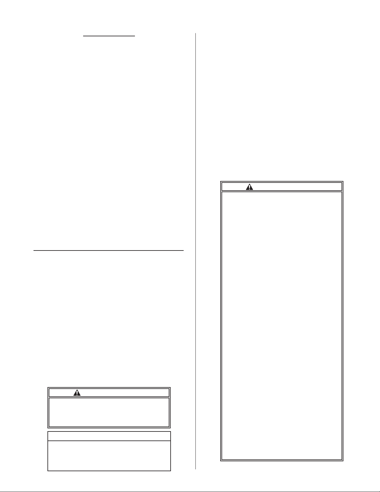
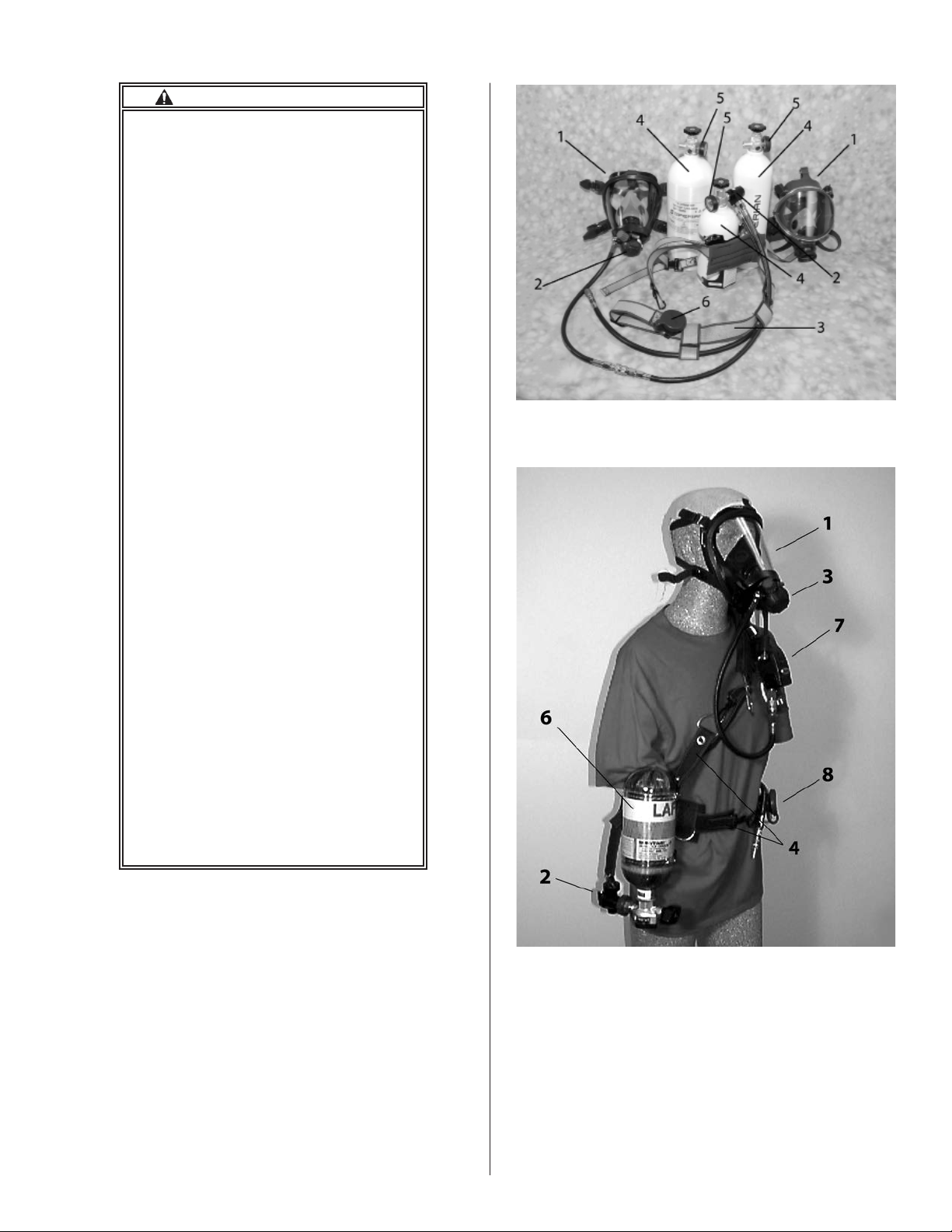
Figure 1A. Low Pressure HIP-PACs
2216 psig & 3000 psig
Figure 1B. High Pressure HIP-PAC, 4500 psig
IV. PARTS LIST (See Figure 1A for low pressure
2216 psig & 3000 psig HIP-PACs and Figure 1B for
high pressure 4500 psig HIP-PAC.)
3
Page 6

Panther HIP-PAC
LOW PRESSURE 2216 PSIG & 3000 PSIG HIP PAC PARTS LIST
Item P/N DESCRIPTION
1 968416 Classic Facepiece, Standard, Black
968417 Classic Facepiece, Small, Black
2120XX Series 21 SeriesFacepieces w/ Drink Tube**
2220XX Series TwentyTwenty Plus Facepieces*
2320XX Series TwentyTwenty Plus Facepieces**
2420XX Series TwentyTwenty Plus Facepieces**
2520XX Series TwentyTwenty Plus Facepieces**
2620XX Series TwentyTwenty Plus Facepieces**
2720XX Series TwentyTwenty Plus Facepieces**
968005 Puma Hood, Standard, Red, Small Nose Cup
968006 Puma Hood, Standard, Red, Medium Nose Cup
968007 Puma Hood, Standard, Red, Large Nose Cup
2 968443 Regulator Assy., First and Second Stages, without
Quick Disconnect
968441 First Stage Pressure Reducer with Quick
Disconnect
961793 Second Stage Regulator with Quick Disconnect
3 968510 Harness Assy., 5 and 10-min., Kevlar
968515 Harness Assy., 15-min., Kevlar
975230 Harness Assy., 5 and 10-min., Nylon
4 975081 5-minute, 2216 psig, All-Aluminum Cylinder and
Valve Assy.
975154 10-minute, 3000 psig, All-Aluminum Cylinder and
Valve Assy.
968512 15-minute, 3000 psig, Hoop-wrapped Cylinder and
Valve Assy.
5 975089 Gauge, 2216 psig
975189 Gauge, 3000 psig
6 961289 Regulator Reciever
* No longer available but still holds current approval. See Matrix for detailed part
numbers and descriptions.
** See Matrix for detailed part numbers and descriptions.
Air Supply Hoses and Air Line Coupling Kits
Lightweight 3/8" PVC Air Supply Hoses w/out Air Line Coupling Kit
930801 25 feet
930802 50 Feet
930804 100 Feet
High Performance 3/8" Neoprene Air Supply Hoses w/out Air Line Coupling Kit
930870 10 Feet
930861 25 feet
930862 50 Feet
930864 100 Feet
Air Line Coupling Kits - Female/Male quick disconnect for 3/8" hoses
930810 Foster
930820 Schrader
930830 Hansen
945007 Hansen Stainless Steel, Two-way Shutoff
930852 Snap-tite
Air Supply Hose Accessories
985237 Gasket for 3/8" hoses
985238 Fitting, Double Male
Accessories
980003 Spectacles Kit, Classic Facepiece, Wire Frame
964054 Spectacles Kit, Classic Facepiece, NexSpex
962260 Spectacles Kit, all 2020 Series Facepieces , Wire
Frame
964044 Spectacles Kit, all 2020 Series Facepieces ,
NexSpex
B140095 Lens Cover, Clear, Classic Facepiece
702019 Lens Cover, Tinted, TwentyTwenty Plus
702028 Lens Cover, Clear, TwentyTwenty Plus
951015 Anti-fog Solution, (1 oz.)
951016 Anti-fog Solution, (16 oz.)
981805 Anti-fog Wipes, (Box of 100)
B140096 Mask Wipes, (Box of 100)
940172 Neck Strap Kit, Classic Facepiece
962232 Neck Strap Kit, TwentyTwenty Facepiece
962869 Neck Strap Kit, TwentyTwenty Plus Facepiece
961710 Headnet Kit, Classic Facepiece, Standard
961730 Headnet Kit, Classic Facepiece, Small
969019 Headnet Kit, TwentyTwenty and TwentyTwenty Plus
Facepieces
962264 Nosecup Kit, TwentyTwenty, Twenty Twenty Plus
Facepiece, Small, Clear
962265 Nosecup Kit, TwentyTwenty, Twenty Twenty Plus
Facepiece, Medium, Clear
Item P/N DESCRIPTION
962266 Nosecup Kit, TwentyTwenty, Twenty Twenty Plus
Facepiece, Large, Clear
702064 Nosecup Kit, TwentyTwenty, Twenty Twenty Plus
Facepiece, Small, Black
702065 Nosecup Kit, TwentyTwenty, Twenty Twenty Plus
Facepiece, Medium, Black
702066 Nosecup Kit, TwentyTwenty, Twenty Twenty Plus
Facepiece, Large, Black
968469 Utility "D" Ring Kit
Communications
964331 TwentyTwenty Plus Radio Communication System
964332 SmallTalk Plus Voice Amplier Kit
964333 TwentyTwenty Plus Radio Communication/SmallTalk Plus
Voice Amplifer Kit
969083 Remote Push-to-Talk Kit
Upgrade and Conversion Kits
P968453 SAR Upgrade Kit, 5 Minute
P968473 SAR Upgrade Kit, 10 Minute
P968535 SAR Upgrade Kit, 15 Minute
P968453 SCBA Conversion Kit, 5 Minute
P968472 SCBA Conversion Kit, 10 Minute
P968540 SCBA Conversion Kit, 15 Minute
Welding Accessories
430000 Welding Shield, Classic Facepiece
430005 Lower Welding Bib, Classic Facepiece
430010 Upper Welding Bib, Classic Facepiece
Tools
962244 Air Klic Removal Tool, TwentyTwenty Plus Facepiece
Fit Testing Accessories
962900 APR Adapter/Qualitative Fit Test Adapter
962920 Quantitative Fit Test Adapter (For use with 962900)
Rebuild Kits (You must be a Certied Technician to rebuild these systems)
975245 First Stage Pressure Reducer Rebuild Kit
961572 Panther Second Stage Regulator Rebuild Kit
4
Page 7

Panther HIP-PAC
HIGH PRESSURE 4500 PSIG HIP PAC PARTS LIST
Item P/N DESCRIPTION
1 968416 Classic Facepiece, Standard, Black
968417 Classic Facepiece, Small, Black
2120XX Series 21 Series Facepieces w/ Drink Tube**
2220XX Series TwentyTwenty Plus Facepieces*
2320XX Series TwentyTwenty Plus Facepieces**
2420XX Series TwentyTwenty Plus Facepieces**
2520XX Series TwentyTwenty Plus Facepieces**
2620XX Series TwentyTwenty Plus Facepieces**
2720XX Series TwentyTwenty Plus Facepieces**
968005 Puma Hood, Standard, Red, Small Nose Cup
968006 Puma Hood, Standard, Red, Medium Nose Cup
968007 Puma Hood, Standard, Red, Large Nose Cup
2 964683 First Stage Regulator
3 961793 Second Stage Regulator
4 968686 Harness Assy.
968680 Harness Assy. For use with COMPASS
5 968713 Intermediate Pressure (IP) Hose
6 917250 Cylinder/Valve
917212 Cylinder/Valve, LAFD, Red
917215 Cylinder/Valve, LAFD, Blue
917218 Cylinder/Valve, LAFD, Black
7 964912 COMPASS Kit, LAFD
964914 COMPASS Kit
964916 COMPASS Kit with Auxiliary Coupler
8 961289 Regulator Reciever
* No longer available but still holds current approval. See Matrix for detailed part
numbers and descriptions.
** See Matrix for detailed part numbers and descriptions.
Air Supply Hoses and Air Line Coupling Kits
Lightweight 3/8" PVC Air Supply Hoses w/out Air Line Coupling Kit
930801 25 feet
930802 50 Feet
930804 100 Feet
High Performance 3/8" Neoprene Air Supply Hoses w/out Air Line Coupling Kit
930870 10 Feet
930861 25 feet
930862 50 Feet
930864 100 Feet
Air Line Coupling Kits - Female/Male quick disconnect for 3/8" hoses
930810 Foster
Air Supply Hose Accessories
985237 Gasket for 3/8" hoses
985238 Fitting, Double Male
Accessories
980003 Spectacles Kit, Classic Facepiece, Wire Frame
964054 Spectacles Kit, Classic Facepiece, NexSpex
962260 Spectacles Kit, all 2020 Series Facepieces , Wire
Frame
964044 Spectacles Kit, all 2020 Series Facepieces ,
NexSpex
B140095 Lens Cover, Clear, Classic Facepiece
702019 Lens Cover, Tinted, TwentyTwenty Plus
702028 Lens Cover, Clear, TwentyTwenty Plus
951015 Anti-fog Solution, (1 oz.)
951016 Anti-fog Solution, (16 oz.)
981805 Anti-fog Wipes, (Box of 100)
B140096 Mask Wipes, (Box of 100)
940172 Neck Strap Kit, Classic Facepiece
962232 Neck Strap Kit, TwentyTwenty Facepiece
962869 Neck Strap Kit, TwentyTwenty Plus Facepiece
961710 Headnet Kit, Classic Facepiece, Standard
961730 Headnet Kit, Classic Facepiece, Small
969019 Headnet Kit, TwentyTwenty and TwentyTwenty
Plus Facepieces
962264 Nosecup Kit, TwentyTwenty, Twenty Twenty Plus
Facepiece, Small, Clear
962265 Nosecup Kit, TwentyTwenty, Twenty Twenty Plus
Facepiece, Medium, Clear
962266 Nosecup Kit, TwentyTwenty, Twenty Twenty Plus
Facepiece, Large, Clear
702064 Nosecup Kit, TwentyTwenty, Twenty Twenty Plus
Facepiece, Small, Black
702065 Nosecup Kit, TwentyTwenty, Twenty Twenty Plus
Facepiece, Medium, Black
702066 Nosecup Kit, TwentyTwenty, Twenty Twenty Plus
Facepiece, Large, Black
968469 Utility "D" Ring Kit
Item P/N DESCRIPTION
Communications
964331 TwentyTwenty Plus Radio Communication System
964332 SmallTalk Plus Voice Amplier Kit
964333 TwentyTwenty Plus Radio Communication/SmallTalk Plus
Voice Amplifer Kit
969083 Remote Push-to-Talk Kit
Welding Accessories
430000 Welding Shield, Classic Facepiece
430005 Lower Welding Bib, Classic Facepiece
430010 Upper Welding Bib, Classic Facepiece
Tools
962244 Air Klic Removal Tool, TwentyTwenty Plus Facepiece
Fit Testing Accessories
962900 APR Adapter/Qualitative Fit Test Adapter
962920 Quantitative Fit Test Adapter (For use with 962900)
Rebuild Kits (You must be a Certied Technician to rebuild these systems)
975245 First Stage Pressure Reducer Rebuild Kit
961572 Panther Second Stage Regulator Rebuild Kit
NOTE
The respirator and hose assemblies are
supplied without quick couplers. The desired
quick coupler assemblies must be purchased
separately. Instructions for assembling quick
couplers and hoses are provided below in
paragraph V, B, “Quick Coupler Assembly.”
5
Page 8
Panther HIP-PAC
V. USE INSTRUCTIONS
A. Air Supply
WARNING
• Compressors, storage cylinders,
valves, regulators, ttings, and other
hardware must be large enough to de-
liver the air volume required by all users at peak demand.
You are responsible for air quality and
compliance with safety and health
codes applicable to your area.
• No more than three (3) lengths of air
supply hose shall be used for the 9308
and 93080 series hose, and no more
than six (6) lengths for the 9649 series
hose.
• The air supply hose inlet must be supplied with 80 to 125 psig air pressure.
• The length of air supply hose must be
10 to 300 feet for the 9308 series hose,
25 to 300 feet for the 93080 series hose,
and 50 to 150 feet for the 9649 series
hose. Do not combine different series of
hoses or coupler assemblies.
• The NIOSH approval applies to the
use of the splitter (suit bypass) only
as speci ed in the “Special or Critical
User’s Instructions.”
• Failure to comply with this Warning
may lead to serious personal injury, serious illness, or death.
1. Ensure that the air supply is Type 1, Grade D, or
better, as described in the Compressed Gas Associa-
tion Commodity Speci cation for Air, G-7.1. Moisture
content, expressed as dewpoint, shall be maintained
at -65°F (-53.9°C) or lower, or less than 24.0 ppm by
volume.
2. Set relief valves at a maximum pressure of 150
psig (1.03 MPa).
B. Quick Coupler Assembly
A male coupler from one of the air line coupler kits listed
in the parts list, paragraph IV, must be assembled to the
open end of the respirator hose. This operation requires
a torque wrench.
1. Respirator Hose
a. Remove the shipping cap plug from the respira-
tor hose.
b. Hold the female threaded tting with a wrench
or vise.
c. Apply thread sealant completely around the male
threads of the coupler.
WARNING
Do not allow the thread sealant to ex-
tend past the last thread of the coupler.
Thread sealant that extends past the
coupler threads can restrict or block air
ow to the user. Failure to comply with
this Warning may lead to serious personal injury, serious illness, or death.
d. Thread the male coupling into the female tting
on the respirator hose. Torque to 90 5 in-lb.
e. Pressurize and check for leaks with a bubbletype leak detector.
f. If leaks are detected, disassemble and repeat
steps a through e.
g. If the leaks persist, remove the hose from service and have repairs made by a SPERIAN-certi ed
technician.
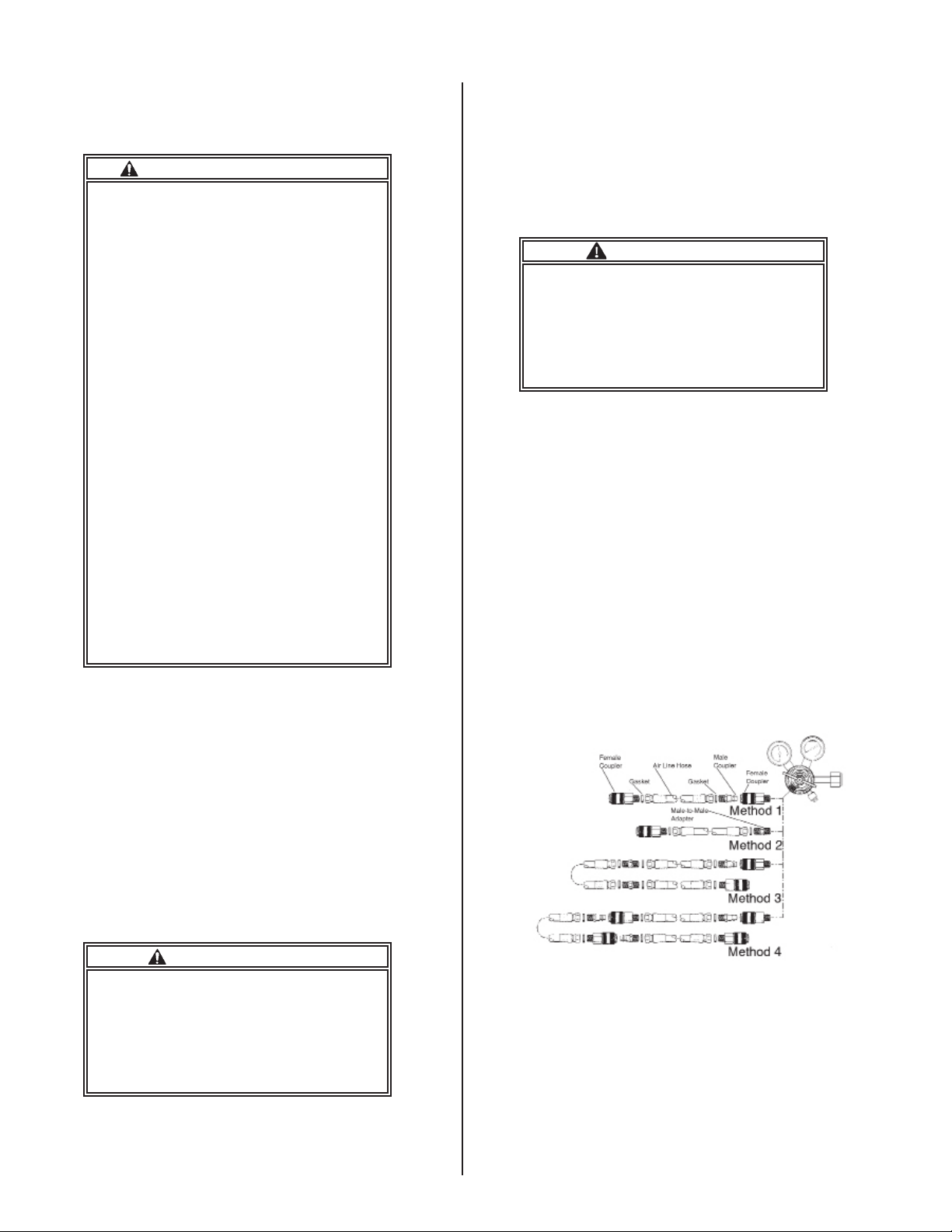
2. Air Supply Hose - Each length of hose is equipped
with a 1/4 inch female NPT swivel nut at each end
and a male-to-male 1/4 inch NPT adapter. The maleto-male adapter may be used to connect two lengths
of hose or connect the hose to the air supply. Four
approved methods of connecting hose lengths and air
supply are illustrated in Figure 2.
WARNING
Carefully inspect and clean all threads
to remove foreign material. Foreign ma-
terial entering the air line can restrict
or block air ow to the user. Failure to
comply with this Warning may lead to
serious personal injury, serious illness,
or death.
Figure 2. Hose Connections
3. When assembling the quick disconnect ttings of
the coupler or the male-to-male adapters to the hose,
verify that the hose gaskets are in place and torque to
90 5 in-lb. Thread sealant is not required.
6
Page 9
Panther HIP-PAC
4. The air supply connection using the 1/4 inch maleto-male adapter illustrated in Method 2 is also approved for use with Methods 3 and 4.
a. Method 1 is preferred when only one length of
hose is required, since it allows the hose to be disconnected from the air supply.
b. Method 3 is preferred when multiple lengths of
hose (maximum of three) are required, eliminating
the cost of quick-disconnect couplers at the hose
junctions.
5. Pressurize and check for leaks with a bubble-type
leak detector. If leaks are detected:
a. Disassemble and repeat steps 3 through 5.
b. If the leaks persist, remove the hose from ser-
vice and have repairs made by a SPERIAN-certied
technician.
WARNING
Always verify that the swivel nut gas-
kets are in place and undamaged before
assembly. Missing or damaged swivel
nut gaskets may allow contaminants to
leak into the system causing illness or
death.
1. Verify that the air cylinder valve is turned off.
2. Verify that the bypass is in the OFF position and
that the cylinder gauge reads full.
3. Depress the shutoff button on the second stage
regulator.
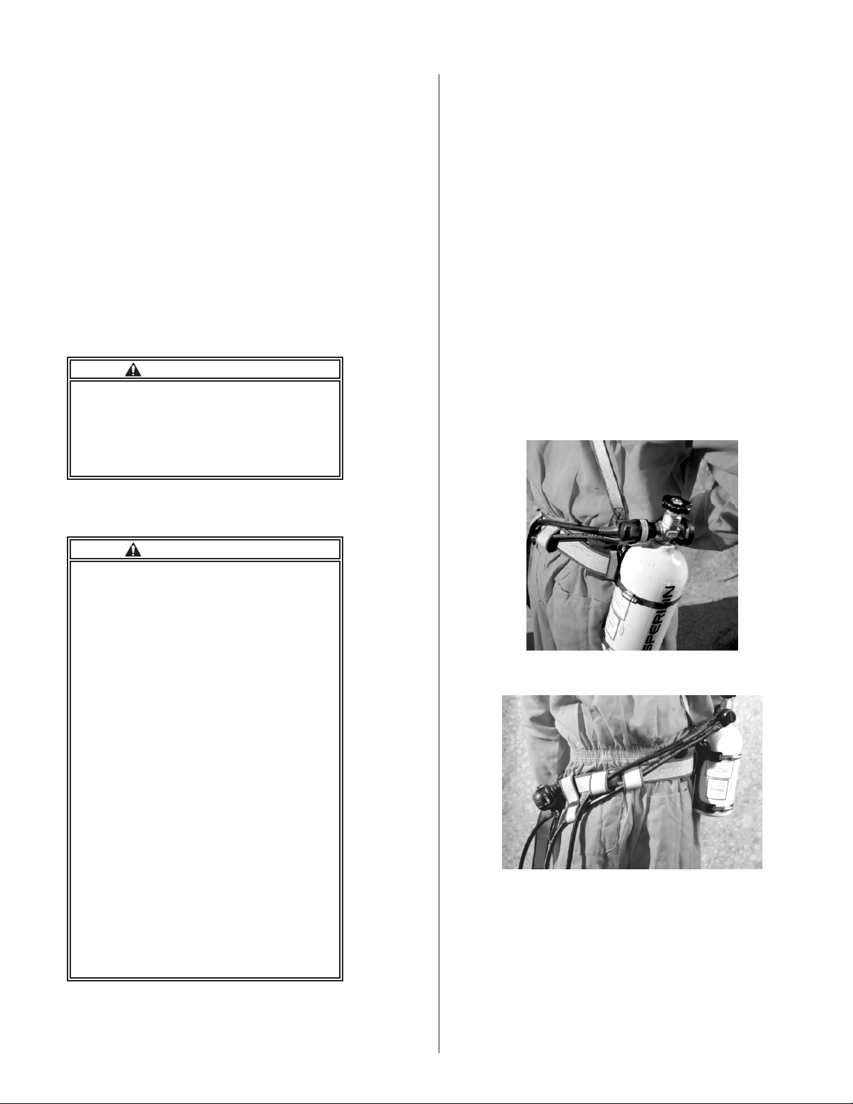
4. Ensure that the waist belt and hip pad (if used) are
properly positioned on the tank mounting bracket belt
loop. See Figure 3.
5. Insert the air line hose through the rst waist belt
loop on the back of the waist belt and the restraint
sleeve located on the waist belt. See Figure 4.
6. Route the second stage hose through the second
loop on the back of the waist belt. Position the second
stage hose so that it routes under your left arm. (If the
hose is too tight, adjust the cylinder nearer the small
of your back.)
NOTE
The following steps 7-10 do not apply to
the 5-minute and 10-minute nylon harness
assembly, P/N 975230.
C. Donning
WARNING
• Always don, remove, and t check the
respirator in a safe, uncontaminated
area.
• The regulator must be attached to the
Panther HIP-PAC air cylinder before
connecting the air line hose to the air
supply. Using the supplied air line without the regulator being attached to the
cylinder could result in loss of air, causing illness or death.
• Verify that the air cylinder valve is
turned off before connecting to the air
supply. Using the Panther HIP-PAC with
the air cylinder turned on while connect-
ed to the air supply will cause loss of air
in the cylinder, resulting in reduced es-
cape time in case of an emergency.
• Always disengage the regulator from
the facepiece and return it to the waist
belt-mounted receiver when not in use.
This will prevent contaminants from
entering the regulator outlet port. Dirt,
dust, and water may enter the regulator,
causing it to malfunction.
• Failure to comply with this Warning
may lead to serious personal injury, serious illness, or death.
Figure 3. Waist Belt and Hip Pad Position
Figure 4. Routing of Hoses
7. Ensure that the regulator receiver is attached to the
waist belt just behind the snap hook.
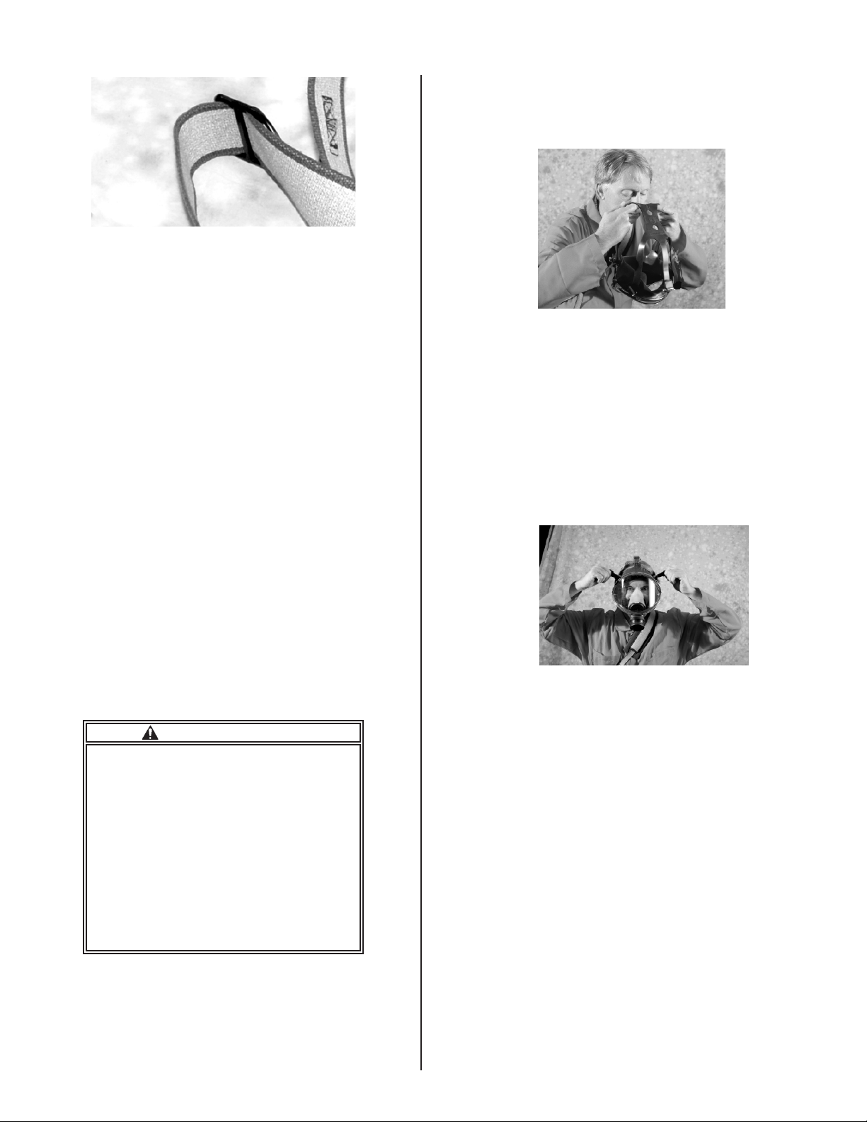
8. Ensure that the waist belt is laced properly through
the D-ring slide and the snap hook. See Figure 5.
7
Page 10
Panther HIP-PAC
Figure 5. Waist Belt D-ring
9. Insert the second stage regulator into the regulator
receiver on the waist belt.
10. Open the (optional) shoulder strap to its maximum
position. Place the shoulder strap over the left shoulder and position the shoulder pad on the top of the left
shoulder. Adjust the shoulder strap to raise the cylinder, and to raise the waist belt into position around
the waist.
11. Position the cylinder so that the cylinder is located
slightly behind the right hip, latch the belt buckle, and
adjust both the waist and shoulder straps (if used)
for comfort. Pull the loose end of the waist strap to
tighten.
12. Connect the air line hose to the remote air
supply.
NOTE
When using Foster ttings, always ensure that the
locking sleeves are rotated to the locked position.
13. When donning the respirator without the optional
shoulder strap, follow the same procedures except
omit step 10.
14. Tighten the AIR KLIC on the facepiece by turning
it clockwise.
15. Verify that the AIR KLIC is secured by trying to
turn it counterclockwise.
ii. If your SCBA is equipped with a neck strap,
place the neck strap over your head.
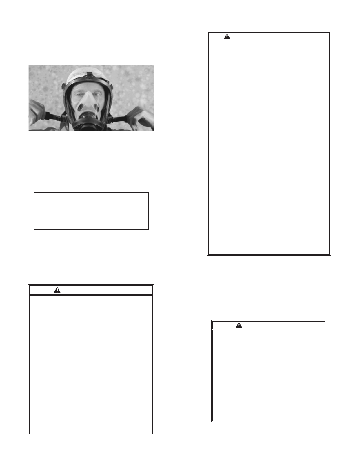
iii. Grasp the lower headstraps as shown in
Figure 6.
Figure 6. Grasp Lower
Headstraps
iv. Place your chin in the chin cup and pull the
straps over your head.
v. Center the facepiece and atten the head-
strap hub on the back of your head.
vi. Tighten the two lower straps. Do not overtighten.
vii. Tighten the temple straps (Figure 7), then
the top strap, until all the headstraps lie at on
your head.
Figure 7. Tighten Upper Straps
WARNING
The AIR KLIC must be held securely
in the nozzle by the ratchet-and-pawl
mechanism. If it is necessary to use a
respirator that has been stored at a tem-
perature below freezing (32°F or 0°C)
prior to using, then DO NOT exhale into
the facepiece until the facepiece has
been properly donned with the nose
cup situated properly on the face and
the regulator installed and activated.
Failure to comply with this Warning
may lead to serious personal injury, serious illness, or death.
16. There are two methods, depending upon which
head harness is used, to secure the Classic™ or
TwentyTwenty Plus facepiece to the user. Both methods are described below.
a. Standard silicone headstrap:
i. Fully loosen the headstraps.
viii. Perform a leak check as described below.
NOTE
When properly adjusted, the headstrap
hub should be centered on the back of
your head, and the lower straps should be
below your ears. Make sure that your chin
is properly recessed in the chin cup.
b. Optional Headnet
i. Inspection
• Classic Facepiece—Ensure that the three
locking fabric straps located across the forehead
are positioned so that they do not slip out from
under the buckles.
• TwentyTwenty Plus Facepiece and 21 Series
Facepiece—Ensure that the three locking fab-
ric straps located across the forehead are fully
inserted into their slots in the rims and that the
locking aps prevent the straps from pulling out
of the slots.
8
Page 11
All Facepieces
ii. Place your chin in the chin cup, pull the
elastic adjustment strap over your head, and
tighten by pulling evenly on both sides. See
Figure 8.
Figure 8. Adjust Headnet
iii. Center the facepiece and fasten the Head-
net with a wiping motion toward the back of
your head.
iv. Retighten the elastic adjustment straps. Do
not overtighten.
v. Perform a leak check as described below.
CAUTION
Do not adjust the t of the facepiece
with the three locking straps at the top
of the headnet. Use the two bottom
straps only.
NOTE
When properly adjusted, the headnet
should be centered on the back of your
head, and the lower straps should be below
your ears.
c. Hood-Style Facepiece
Panther HIP-PAC
WARNING—Continued
cleaning and disinfecting, anti-fog solution
(SPERIAN P/N 951015, 951016, OR 981805)
must be applied to the inside of the lens.
• The Challenge® NXT, PVC lens, neoprene
neck seal, and adhesive all may react
in a different manner when exposed to
chemicals or chemical mixtures. You must
verify that none of the components of the
hood will degrade against the chemicals or
mixtures to which it may be exposed.
• It is vital to ensure that you have objective
evidence that the hood will be able to
maintain its integrity against the expected
chemical exposure during operations. This
can be accomplished by tests you conduct
or by contacting SPERIAN for further
information. Listed below are a few, but not
necessarily all, chemicals that are known
to degrade or destroy the PVC material.
Do not use the hood in environments
containing these chemicals:
• Acetone
• Bleach
• Carbon tetrachloride
• Methanol
• Methyl ethyl ketone
• Nitric acid
• Toluene
• Trichloroethylene
• Failure to comply with this warning may
lead to serious personal injury, serious
illness, or death.
i. Fully loosen the suspension straps.
ii. Grasp the hood-style facepiece by the neck
seal and pull the neck seal over your head.
WARNING
The SPERIAN hood-style facepiece:
• Must be worn in conjunction with an SAR
and/or SCBA and used as specied in
SPERIAN’s instructions.
• When donned and used with its SAR/
SCBA, will reduce, but not eliminate the
inhalation of contaminants.
• Does not protect against falling objects or
projectiles.
• Must not be worn around open ames. It
must not be used for structural re ghting,
underwater activities, or abrasive blasting.
• Must not be used unless a satisfactory t
is obtained.
• Must not be reused if contaminated.
• Must not be altered or modied in any
manner.
• Requires that the wearer must assure
that the neck seal is not compromised by
hair or clothing when in use.
• Requires that after each use and/or
iii. Position the nose cup on your face, then
simultaneously tighten the two suspension
straps.
D. Fit Check
WARNING
• Conduct t checks only in a safe, un-
contaminated environment.
• Do not use this respirator in a con-
taminated atmosphere if you do not
obtain a satisfactory seal during the t
check. If a seal was not obtained, repo-
sition the facepiece, check the straps,
and perform the t check again. Failure
to obtain a satisfactory seal could allow contaminants to leak into the face-
piece, causing illness or death. Failure
to comply with this Warning may lead to
serious personal injury, serious illness,
or death.
9
Page 12

Panther HIP-PAC
NOTE
Steps 1-3 apply to conventional facepieces
only.
1. Place the palm of your hand over the AIR KLIC as
shown in Figure 9.
2. Inhale and hold your breath for a few seconds.
The facepiece should collapse on your face without
leaking.
Figure 9. Fit Check for Conventional Facepiece
3. If the facepiece leaks, reposition it, check the
straps, and repeat the t check.
NOTE
Steps 4-5 apply to Puma hood-style
facepieces only.
4. Don and pressurize the hood-style facepiece as
shown in Figure 10.
NOTE
The second stage regulator release buttons
must be pressed simultaneously to remove
the regulator from the holder.
8. Insert the regulator into the AIR KLIC on the facepiece and press rmly until you hear both release but-
tons snap into place.
NOTE
• A CLICK will be heard when each AIR
KLIC button is properly engaged.
• Do not press the release buttons when
installing the regulator.
WARNING
Rotate and tug the regulator to ensure
that both release buttons are properly
engaged in the AIR KLIC. Do not push
the release buttons while verifying the
engagement of the regulator. Do not
press the release buttons unless you
intend to remove the regulator from the
facepiece. Pressing both release but-
tons during or after installation onto the
facepiece could result in inadvertent
regulator disengagement, causing serious injury or death.
9. Take a sharp, deep breath to activate the regulator.
10. Take several breaths to check the ow of air.
11. Press the black rubber override button on the
second stage regulator to ensure that it is operating
properly.
12. Quickly open and close the bypass valve to ensure that it is operating properly.
13. The Panther HIP-PAC is now ready for use.
Figure 10. Fit Check for Hood-style Facepiece
5. Hold your breath for several seconds and listen for
audible leaks.
6. When a satisfactory t is obtained, verify that the
respirator hose is connected to the air line hose and
the air line hose is connected to an air source set for
the correct pressure.
7. Remove the second stage regulator from the waist
strap regulator holder by pressing the two release
buttons.
WARNING
Always close the regulator receiver
cover to prevent contaminants from
collecting in the receiver. Failure to
comply with this Warning may lead to
serious personal injury, serious illness,
or death.
WARNING
• Entry into hazardous atmospheres with
the Panther HIP-PAC must be done while
connected to the air line. Do not use the
escape cylinder air supply for entry.
• Ensure that the escape cylinder is full.
• The Panther HIP-PAC has a rated service
time of 5, 10, or 15 minutes.Under average
conditions, you will have up to 5, 10, or 15
minutes in which to escape from a toxic
environment. Stress and exertion may
consume extra air and reduce service time.
Know escape routes in advance and the
time required to travel them.
• Always follow established safety
procedures when exposed to atmospheres
that are hazardous or immediately
dangerous to life or health.
• Failure to comply with this Warning may
lead to serious personal injury, serious
illness, or death.
10
Page 13

Panther HIP-PAC
E. Emergency Exit
1. If the air line supply is cut off while the user is in a
hazardous atmosphere, turn the cylinder valve of the
Panther HIP-PAC counterclockwise at least one full
turn to start the ow of air from the cylinder.
2. If required for escape, disconnect the air line hose
from the Panther HIP-PAC respirator hose.
3. Proceed immediately to fresh air.
4. When in a safe environment, remove the facepiece
and turn the cylinder valve clockwise to shut off air
from the cylinder.
CAUTION
Do not overtighten the cylinder valve.
Damage to the valve seat could result.
F. Emergency Operation
1. PROBLEM: Restricted or interrupted air ow
a. Open the bypass valve by turning the red knob
on the second stage regulator counterclockwise un-
til the desired constant air ow is achieved.
WARNING
Activating the bypass valve rapidly depletes your air supply. Immediately exit
to a safe area. Failure to comply with
this Warning may lead to serious personal injury, serious illness, or death.
G. Dofng
WARNING
• Follow all appropriate decontamination procedures before dofng the Pan-
ther HIP-PAC.
• Doff the Panther HIP-PAC only in a
safe area.
• Failure to comply with this Warning
may lead to serious personal injury, serious illness, or death.
1. Press the second stage regulator shutoff button.
2. Press the two release buttons and remove the regulator from the facepiece.
WARNING
Always disengage the regulator from
the facepiece and return it to the waist
belt-mounted receiver when not in use.
This will prevent contaminants from en-
tering the regulator outlet port. Dirt and
dust may enter the regulator, causing it
to malfunction. Failure to comply with
this Warning may lead to serious personal injury, serious illness, or death.
3. Disconnect from the remote air source, or close the
cylinder valve.
b. IMMEDIATELY exit to a safe area.
c. Have the HIP-PAC inspected and/or repaired by
a certied repair technician before reuse.
2. PROBLEM: First-Breath-On failure
a. Press the black rubber manual override button on
the front of the regulator to start air ow.
b. IMMEDIATELY exit to a safe area.
c. Have the second stage regulator inspected and/
or repaired by a certied repair technician before
reuse.
3. PROBLEM: Free ow
a. If the regulator will not shut off (free ows) during
extremely heavy breathing, exhale forcefully. The
regulator should return to normal ow.
b. If the free ow continues, open and close the by-
pass once, or depress the manual override button
once.
c. If the problem persists, IMMEDIATELY exit to a
safe area.
d. Have the HIP-PAC inspected and/or repaired by
a SPERIAN-certied repair technician before reuse.
4. Press the override button on the second stage regulator to vent air from the Panther HIP-PAC.
5. Push the second stage regulator into the waist
strap-mounted regulator holder until it clicks.
6. Place your thumbs under the headstrap buckles,
loosen the lower straps, and remove the facepiece.
7. Unsnap the waist strap buckle and remove the
Panther HIP-PAC.
8. Prepare the Panther HIP-PAC for storage.
CAUTION
If the Panther HIP-PAC is to be trans-
ported unsecured for long periods of
time, the rst stage connection to the
cylinder valve must be wrench-tight.
11
Page 14

Panther HIP-PAC
H. Use of the 21 Series Drink Tube
The drink tube allows the user to consume uids
while wearing the 21 Series facepiece and is compatible with a MIL-C-51278 water canteen cap.
WARNING
• Using the drink tube in a contaminated
area or after leaving a contaminated
area may expose you to contaminants.
Use the drink tube in accordance with
instructions provided by the IC or ICS.
• Failure to comply with this warning
may lead to personal injury, illness, or
death.
1. While wearing the 21 Series facepiece, remove
the drink tube coupling from the retainer and insert
it into a MIL-C-51278 canteen cap.
2. Use mouth movements to insert the drink tube
mouthpiece inside the nose cup into your mouth.
3. Hold the canteen upside down higher than the
mouthiece and suck the uid into your mouth as
shown in Figure 11.
4. When through drinking, turn the canteen right
side up and remove the mouthpiece from your
mouth.
5. Remove the coupling from the canteen cap and
return the coupling to the drink tube retainer.
VI. MAINTENANCE
WARNING
Specialized processes are required to
disinfect and decontaminate a respira-
tor. You MUST follow the instructions
of the manufacturer who supplies the
disinfecting or decontamination equip-
ment or chemicals. Failure to comply
with this Warning may lead to serious personal injury, serious illness, or
death.
CAUTION
• DO NOT clean the facepiece with the
regulator attached.
• You must ensure that this respirator is
not damaged when using disinfecting or
decontamination equipment or chemicals.
• The facepiece lens can be scratched
through careless or abusive handling.
DO NOT use abrasive cleaners or pads.
DO NOT towel dry.
NOTE
Inspect the Panther HIP-PAC for defects
before and after each use, and at least once
monthly if not used. Repair as necessary,
clean and disinfect after each use, and store
properly to assure that the Panther HIP-
PAC is maintained in satisfactory working
condition. Keep a record of inspection
and repair dates and results. Refer to the
inspection table in the back of this manual.
Figure 11. 21 Series Drink Tube
A. Conventional Facepiece Cleaning
NOTE
Silicone and rubber parts of the facepiece
may be cleaned between washings with
SPERIAN Mask Wipes, P/N 140096.
1. Make a cleaning solution of warm water and a
mild detergent.
2. Fully immerse the facepiece in the solution.
3. Agitate the facepiece and gently clean with a soft
brush.
4. Thoroughly rinse the facepiece in fresh water,
paying particular attention to removal of all soap
residue from the exhalation valve. If possible, direct
running water onto the exhalation valve.
5. Allow the facepiece to drip dry. Warm air may be
used to speed up drying.
12
Page 15

Panther HIP-PAC
NOTE
Repeated cleaning may require
reapplication of anti-fog coating to the
facepiece lens. Use only SPERIAN AntiFog Solution, P/N 951015 (1 oz.), or P/N
951016 (16 oz.).
6. After cleaning, three drops of anti-fog solution may
be applied to the inner surface of the lens with a lintfree cloth. Allow the coating to dry for 15 minutes
before using the facepiece. The 2720 series of the
Twenty-Twenty Plus facepiece has a permanent antifog coating. Anti-fog solution does not need to be applied.
7. Hold the facepiece rmly against your face and exhale several times to ensure that the exhalation valve
functions smoothly.
8. Cleaning the 2120 Series Facepiece Drink Tube
a. Remove the retainer, internal & external drink
tube from the facepiece. The internal drink tube is
removed by pulling the drink tube from inside the
nosecup until the tube comes off the plastic barb.
The external drink tube is removed by using a 1
inch spanner wrench to unscrew the connector cap
and pulling the drink tube off of the plastic barb.
The retainer can be pulled off of the left side connector.
b. Rinse the insides of the retainer, internal & ex-
ternal drink tubes with warm water, removing any
residue. Rinse thoroughly and allow the components to air dry.
c. Re-install the external drink tube over the barb
of the at side of the plastic connector. Place the
adapter into the connector slot, and tighten on the
o-ring seal and screw connector cap with the 1
inch spanner wrench. Do not overtighten. Place
the retainer over the connector cap and place the
external drink tube/valve inside the retainer. Re-
install the internal drink tube by placing the con-
necting end of the tube through the nosecup hole
and over the adapter’s internal plastic barb. Orient
internal tube to the user’s preference by rotating
drink tube around barb.
B. Hood-style facepiece cleaning
WARNING
• It is the user’s responsibility to ensure
that the cleaning process chosen provides
adequate disinfection or decontamination.
• Specialized processes are required to
disinfect and decontaminate a respirator.
You MUST follow the instructions of
the manufacturer who supplies the
disinfecting or decontamination equipment
or chemicals. Use ONLY the sanitizing
products listed in this manual to disinfect
WARNING—Continued
and decontaminate the full facepiece hood.
• After each use and/or after cleaning and
disinfecting, SPERIAN anti-fog solution,
(P/N 951015, 951006, or 981805) must be
applied to the inside of the lens.
• Failure to comply with this warning may
lead to serious personal injury, serious
illness, or death.
CAUTION
• DO NOT clean the hood-style facepiece
with the regulator attached.
• You must ensure that this respirator
is not damaged by disinfecting
or decontamination equipment or
chemicals.
• The hood-style facepiece lens can be
scratched through careless or abusive
handling. DO NOT use abrasive cleaners
or pads. DO NOT towel dry.
• Sanitizing solutions containing
chloride bleach (such as a “hypochlorite
solution”) may damage the hood-style
facepiece lens.
NOTE
• ANSI Z88.2 1992 also provides
information and guidelines on the cleaning
of respirators.
• After each use, prior to cleaning and
disinfecting, inspect the inside of the lens
for an anti-fog appliqué. If an appliqué is
present, inspect it to verify that it is still
adhering to the lens properly. If the antifog appliqué is delaminating from the lens,
remove it from the inside of the lens by
lifting one edge of the appliqué and gently
peeling it away, being careful not to damage
the lens.
• Once the appliqué has been removed, it
is not necessary to replace it with another
appliqué. Application of SPERIAN Anti-fog
Solution, P/N 951015, 951016, or 981806,
to the inside of the lens is adequate.
1. Make a cleaning solution of warm water (120° F
or 48° C maximum) and a mild detergent.
2. Immerse the hood-style facepiece in the solution
until the exhalation valve is covered.
3. Agitate it and gently clean it with a soft brush.
4. Thoroughly rinse the hood in fresh water, paying
particular attention to removal of all soap residue
from the exhalation valve. If possible, direct running
water onto the exhalation valve.
5. Disinfect the hood using one of the following
sanitizing products: ARI Sanitizer Deodorizer–ARI,
Orchard Hill, GA; Lysol Disinfectant; or Simple
13
Page 16

Panther HIP-PAC
Green All Purpose Cleaner.
6. Allow the hood to drip dry. Warm air may be used
to speed up drying.
7. Hold the hood facepiece inner mask rmly
against your face and exhale several times to ensure that the exhalation valve functions smoothly.
8. After cleaning and disinfecting the hood, liberally apply SPERIAN anti-fog solution, P/N 951015,
951016, or 981805 to the inside of the lens and
allow it to dry thoroughly.
C. Second Stage Regulator Cleaning
WARNING
• Do not allow water or cleaning solutions to enter the breathing system or
the regulator. Dirt, dust, or soap residue
could degrade regulator performance
causing it to fail, possibly resulting in
injury or death.
• Do not submerge the regulator in water or cleaning solutions. It may be partially submerged only as instructed in
step 6 below.
• Failure to comply with this Warning
may lead to serious personal injury, serious illness, or death.
NOTE
• Always hold the regulator with the outlet
facing downward during washing and
rinsing.
• The Protective Cleaning Cap, P/N 873004,
may be used to seal the Panther second
stage regulator to prevent contaminants
from entering the regulator outlet. See
Figure 12.
1. Make a cleaning solution of warm water and a mild
detergent.
2. Have a bucket of fresh water available for rinsing.
3. With the regulator facing downward, clean the exterior surfaces and the interior of the outlet tube with
a soft brush.
4. With the regulator facing downward, immediately
rinse the exterior surfaces and the interior of the outlet
tube with fresh water. Scrub excess soap away with
the brush.
5. Dry with a clean cloth or with low pressure (15 psig
maximum) clean (breathing grade) air.
6. If dirt or debris interferes with the First-Breath-On
mechanism, clean it as follows:
a. Lift the edge of the rubber manual override button
with a small, at-blade screwdriver, and peel it off.
b. Place the protective cap over the outlet tube.
c. Hold the regulator with the cover facing down-
ward and rinse in a shallow bucket of fresh water.
d. Allow the water to drain, and dry with low pressure air (15 psig maximum).
e. Replace the manual override button.
D. Exterior Surfaces Cleaning
CAUTION
The hoses, backpack harness, frame,
and cylinder and valve assembly may
be cleaned with a damp cloth or a mild
soap and warm water solution. Rinse
thoroughly and air dry or wipe with a
clean cloth.
E. Inspection (see page 21)
F. Repair (see page 22)
WARNING
Before disassembly, make sure that all
air is bled from the lines. Shut off or
deplete the air supply to prevent equip-
ment damage or personal injury. Failure
to comply with this Warning may lead to
serious personal injury, serious illness,
or death.
Figure 12. Protective Cleaning Cap
14
CAUTION
User repair of the Panther HIP-PAC is
limited to replacement of components
listed on the NIOSH approval label and
repairs described in this section. Disassembly should be performed only to the
extent necessary to replace the components. To protect your warranty and the
NIOSH certication on the equipment,
all other repairs must be done only by
SPERIAN-certied technicians. If there
are none at your facility, consult your
SPERIAN distributor for the repair facility nearest you.
.
Page 17

Panther HIP-PAC
NOTE
All SPERIAN-certied Technicians
are required to remain current on new
procedures and parts through SPERIAN’s
published Technical Bulletins, technical
manual revisions, and certication
seminars.
G. Functional Testing (see page 23)
Perform functional tests after cleaning or repair. After
testing, ll the cylinder and store the Panther HIP-PAC.
H. Cylinder Maintenance and Recharging
WARNING
• You must read and understand all warnings
and instructions provided on the cylinder
DOT warning label and in instruction
manuals before using the cylinder/valve
assembly.
• Only trained personnel may store, ll,
service, maintain, handle, use, or dispose
of cylinders used with this HIP-PAC. Follow
the guidelines of the Compressed Gas
Association (CGA) pamphlets P-1, C-1,
C-2, C-6, C-6.1, C-6.2, G-7, and G-7.1, as
appropriate. Always follow established
safety precautions when recharging
cylinders.
• Do not alter cylinders used with this HIPPAC.
• Fill only to the stamped service pressure.
Do not overll.
• Do not ll a leaking cylinder. Depressurize
immediately.
• Do not tamper with the safety pressure
relief device. Rapid depressurization when
the safety pressure relief device activates
will cause excessive noise. During rapid
depressurization, cylinders may become
ballistic and cause injury. Stay clear of
cylinders when the safety relief device is
activated.
• Do not ll the cylinder if unraveling or
charring of composite bers occurs.
• Do not ll or use the cylinder if you have
any doubt about its suitability for recharge.
Return it to a certied hydrostatic test
facility.
• Do not expose cylinders used with this
HIP-PAC to open ame or heat sources
which may heat the cylinder to 350°F.
Cylinders damaged by re or exposed to
heat of 350°F must be destroyed.
• Repainted or renished cylinders must be
hydrostatically tested before reuse.
WARNING—Continued
• Do not ll a composite cylinder if it
is not marked as being hydrostatically
tested within three (3) years. Do not ll an
aluminum cylinder if it is not marked as
being hydrostatically tested within ve (5)
years.
• Do not ll or use composite cylinders
older than 15 years. Depressurize and
destroy these cylinders.
• Inspect cylinders before each lling.
Remove cylinders from service which have
cuts, gouges, dings, bulges, corrosion,
etc. A special internal and external visual
inspection of cylinders must be completed
at least every hydrostatic test. Follow the
guidelines of CGA 6.2.
• Do not use caustic paint strippers or
corrosive cleaners.
• Do not ll with oxygen.
• Do not remove, obscure, or alter any
labels on HIP-PAC cylinders.
• Failure to comply with this Warning may
lead toserious personal injury, serious
illness, or death.
1. Inspection
After each use and prior to recharging, each air
cylinder shall be subjected to a thorough visual
inspection.
WARNING
Do not ll any cylinders that are damaged,
you suspect may be damaged or unsafe,
or are out of conformance with applicable
hydrostatic test dates. Damaged cylinders
must be inspected by an approved
hydrostatic test facility and repaired as
required before being lled. Failure to
comply with this warning may lead to
serious personal injury, serious illness, or
death.
a. Aluminum Cylinders
Ensure that no more than ve years have elapsed
since the last hydrostatic test has been performed,
as indicated by the most recent date stamped into
the cylinder shoulder. Inspect the exterior of the
cylinder for dents, gouges, or rusted areas, and
evidence of exposure to high temperature such as
darkened or blistered paint, charred decals, melted
or distorted gauge lens, etc.
15
Page 18

Panther HIP-PAC
b. Composite Cylinders
Ensure that no more than three years have elapsed
since the last hydrostatic test has been performed
for the 3000 psig, hoop wrapped cylinder and ve
years for the 4500 psig fully wrapped ber cylinder,
and that the cylinder is less than 15 years old. Inspect the exterior of the cylinder for dents, gouges,
or cuts which have penetrated and caused separation or unraveling of the composite overwrap. Watch
for evidence of exposure to high temperature, such
as darkened or blistered paint, charred overwrap or
decals, melted or distorted gauge lens, etc.
c. Cylinder Valve
The cylinder valve should also be examined for ob-
vious external damage such as a deformed handwheel, inaccurate or inoperative pressure indicator,
damaged threads on the outlet connection, or other
evidence of impact or exposure to extreme heat.
If internal contamination is suspected, remove the
cylinder valve and inspect the interior of the cylinder. The cylinder valve overhaul cycle should be as
follows. For steel, all aluminum, or fully wrapped
carbon ber cylinders, overhaul the valve at every
hydrostatic retest (5 year cycle). For hoop wrapped
cylinders, overhaul the valve at every other hydrostatic retest (6 year cycle).
d. Additional Information
i. Additional information on cylinder inspection
and maintenance can be found in CGA pamphlet
C-6, “Standards for Visual Inspection of Com-
pressed Gas Cylinders,” CGA pamphlet C-6.1,
“Visual Inspection of High Pressure Aluminum
Cylinders,” or CGA pamphlet C-6.2, “Guidelines
for Visual Inspection and Requalication of Fiber
Reinforced High Pressure Cylinders,” available
from the Compressed Gas Association, Inc. If
there is any doubt about the suitability of a cylinder to recharge, it should be returned to a certied hydrostatic retest facility for expert examination and retesting.
ii. A comprehensive listing of all licensed hydrostatic test stations is available from the Department of Transportation.
2. Filling Procedure
a. Air Purity
Unless safety and health codes in your area specify
otherwise, air cylinders should be relled with compressed air meeting the purity requirements for
Type 1, Grade D Gaseous Air as specied by the
Compressed Gas Association Commodity Speci-
cation for Air, publication G-7.1. The moisture content, expressed as dewpoint, shall be maintained
at -65°F (-53.9°C) or lower, or less than 24.0 ppm
by volume moisture content. UNDER NO CIRCUMSTANCES SHALL AN AIR CYLINDER BE FILLED
OR PARTIALLY FILLED WITH OXYGEN.
b. Maximum Fill Pressure
Determine the service pressure of the cylinder prior
to lling. Composite and aluminum cylinders may
be lled only to the service pressure indicated on
the cylinder label. Composite and aluminum cylin-
ders must never be lled to a pressure greater than
the marked service pressure.
c. Filling Procedure
i. The ll station must be constructed and
equipped in accordance with applicable state industrial safety codes.
ii. The cylinder may be partially immersed (DO
NOT submerge the cylinder valve) in a water
bath to minimize the temperature rise that oc-
curs as the cylinder is lled. The ll hose should
be equipped with a restraining cable to prevent
uncontrolled “whipping” in case of hose failure.
iii. After connecting the ll hose, open the cylin-
der valve fully. A separate metering valve must
be used to control the ll rate. Fill the cylinder
slowly, at a rate not exceeding 500 psig per minute. (Use caution if faster recharging rates are
used.) After the initial lling, allow the cylinder
to cool to room temperature, then “top off” the
cylinder to achieve full service pressure.
iv. Use particular care to ensure that an air cyl-
inder is never connected to a source capable
of supplying air at a pressure greater than the
maximum service pressure of that cylinder.
v. Close the cylinder valve when the cylinder is
full.
vi. Slowly bleed pressure from the lling lines.
vii. Disconnect the lling line.
viii. Let the cylinder cool and check the gauge
reading. Top off if necessary.
d. Storage
Air cylinders should be recharged as soon as prac-
tical after use. Cylinders should not be stored par-
tially charged, for two reasons:
i. If used without recharge, the service duration
of the apparatus is reduced.
ii. The safety relief device is designed speci-
cally to protect a fully charged cylinder from the
effects of a re.
For maximum safety, the cylinders should be stored
fully charged.
If the cylinder is stored empty and the valve is inadvertently left open, humid atmospheric air may
enter the cylinder and result in interior corrosion.
If a HIP-PAC is to be maintained in “standby” mode,
i.e., available for immediate emergency usage, the
cylinder pressure gauge should be checked at least
once a month to assure that the cylinder is charged
to full service pressure. Place the cylinder in a suit-
able safety sleeve or lling area.
16
Page 19

Panther HIP-PAC
I. Cold Weather Operation and Maintenance
Operation of the Panther HIP-PAC in cold weather, 32°F
(0°C) or colder, requires the user to be aware of the potential problems caused by the combination of moisture
and low temperatures.
WARNING
• Moisture entering the regulator sys-
tem, either from moisture in the cylinder
air or by external means, e.g., overspray
during operations or inclement weather
conditions, may cause regulator sys-
tem freezeup, restricting or stopping air
ow to the user. This could result in se-
rious injury or death to the user.
• Recharge the cylinders with Grade
D or better air conforming to Com-
pressed Gas Association Specication
G-7.1. Moisture content, expressed as
dewpoint, shall be maintained at -65°F
(-53.9°C) or lower, or less than 24.0 ppm
by volume. Air exceeding this moisture
content may cause regulator system
freezeup, restricting or stopping air
ow to the user. This could result in se-
rious injury or death to the user.
NOTE
• Moisture can cause regulator system
freezing problems even if the ambient air
temperature is above freezing. The air
owing from the HIP-PAC cylinder through
the regulator system decreases from
cylinder pressure to near atmospheric
pressure very rapidly. As this pressure
decreases, the air rapidly expands, causing
the air and therefore the regulator to cool.
• Although the ambient temperature may be
above 32°F (0°C), the temperature inside
the regulator system may be considerably
lower (below freezing).
• SPERIAN recommends that HIP-PACs
used on a routine basis or HIP-PACs
kept for emergency use be stored at
temperatures above 32°F (0°C). HIP-PACs
stored at temperatures below 32°F (0°C)
may need to be warmed to at least 32°F
(0°C) prior to use if ice has formed on the
facepiece exhalation valve, AIR KLIC, and/
or quick-disconnects.
SPERIAN recommends a “change of season” inspection
and increased attention to your preventive maintenance
during cold weather conditions. The following recommended inspections and procedures will help prevent
cold weather problems; however, cold weather conditions may also cause other problems not listed below.
1. Air Supply
NOTE
Cold weather conditions require very dry
air. Moisture entering the HIP-PAC may
cause icing and equipment malfunction.
a. Test compressor(s) for air quality and dewpoint
prior to the cold season.
b. Recharge the cylinders with Grade D or better
air conforming to Compressed Gas Association
Specication G-7.1. Moisture content, expressed
as dewpoint, shall be maintained at -65°F (-53.9°C)
or lower, or less than 24.0 ppm by volume.
c. Prevent any moisture from entering the HIPPAC.
d. Remove ice and water from cylinder valve threads
prior to lling in cold weather conditions.
2. Facepiece and Exhalation Valve
a. The facepiece must be protected from moisture
during cold weather conditions to reduce ice formation on the facepiece lens, in the AIR KLIC, and in
the exhalation valve.
b. Prior to donning the facepiece in cold weather,
visually inspect the lens, AIR KLIC, and exhalation
valve for ice.
c. If ice is present, warm the facepiece to melt the
ice. Ice may be melted by placing the facepiece inside outerwear near the body to warm.
d. Ice in the exhalation valve may be melted by at
least six to eight exhalations onto the exhalation
valve.
e. Verify the proper function of the exhalation valve
by performing a positive pressure exhalation test
and negative pressure leak check as follows.
f. Don the facepiece as specied in the Donning
section of this manual.
g. Perform a positive pressure exhalation test:
i. Take a deep breath, and place your hand over
the AIR KLIC.
ii. Exhale normally. The exhalation valve must
function normally.
iii. If the exhalation valve does not function or it is
difcult to exhale, remove the facepiece.
iv. Exhale on the exhalation valve at least six to
eight more times to melt the ice.
v. Reposition the facepiece, check the straps,
and repeat the test.
vi. If the exhalation valve continues to malfunc-
tion, remove the facepiece from service.
vii. Have the facepiece inspected and/or repaired
by a SPERIAN-certied repair technician before
reuse.
h. Perform a negative pressure leak check:
i. Place your hand over the AIR KLIC.
ii. Inhale and hold your breath for a few seconds.
17
Page 20

Panther HIP-PAC
The facepiece should collapse on your face and
remain collapsed for several seconds without
leaking.
iii. If the facepiece leaks, exhale onto the ex-
halation valve at least six to eight more times.
Reposition the facepiece, check the straps, and
repeat the leak check.
iv. If the facepiece continues to leak, remove it
from service.
v. Have the facepiece inspected and/or repaired
by a SPERIAN-certied repair technician before
reuse.
i. Again, visually check to verify that the facepiece,
lens, AIR KLIC, and exhalation valve are ice-free.
WARNING
If it becomes necessary to remove the
facepiece when using the HIP-PAC,
move to a non-hazardous area rst.
Failure to comply with this Warning
may lead to serious personal injury, serious illness, or death.
j. If the ambient temperature is near or below freezing, place the facepiece and regulator under outer-
wear to keep it warm in case reuse is necessary.
3. Second Stage Regulator
WARNING
• Ice on the second stage regulator AIR
KLIC buttons or the facepiece AIR KLIC
adapter may prevent proper engage-
ment of the regulator.
• The user must ensure that the regula-
tor is properly engaged by rotating and
tugging the regulator to verify that both
release buttons are properly engaged in
the AIR KLIC.
• Failure to comply with this Warning
may lead to serious personal injury, serious illness, or death
a. The second stage regulator must be protected
from moisture during cold weather conditions to
avoid ice buildup on its exterior surfaces. Ice can
interfere with emergency bypass operation or AIR
KLIC button function, which can hinder regulator
removal from the facepiece or from the regulator
receiver.
b. Visually inspect the external surfaces of the regulator for ice prior to use.
c. If ice is present, it may be melted by placing the
regulator inside outerwear near the body to warm.
d. Again, visually inspect the regulator for ice, then
check the red bypass knob and the AIR KLIC buttons for proper function.
te. Should ice form on the regulator while the regulator is in the facepiece, it will continue to function
properly. When it becomes necessary to remove
the regulator, rotate the regulator to break off the
ice, then remove the regulator from the facepiece.
f. If the AIR KLIC buttons are frozen and the regula-
tor cannot be removed, do not force the buttons.
Move to a non-hazardous area, depress the regulator shutoff button, and remove the facepiece and
regulator as a unit.
g. If the shutoff button is nonfunctional, turn off the
air supply at the cylinder valve.
h. Remove the facepiece and regulator as a unit.
i. Warm the facepiece and regulator until the normal
function of the AIR KLIC button and/or the shutoff
button returns.
j. Should ice form on the regulator while the regulator is in the regulator receiver, rotate the regulator
to break off the ice, then remove the regulator from
the regulator receiver.
k. If the AIR KLIC buttons are frozen and the regu-
lator cannot be removed from the receiver, do not
force the buttons. Unbuckle the waist belt, and
place the belt, regulator receiver and regulator under outerwear next to your body to warm it until the
AIR KLIC button functions properly.
4. Regulator Receiver
a. During cold weather operation, keep the regula-
tor receiver cover in place on the regulator receiver
to keep out moisture and debris.
b. Visually inspect the regulator receiver for ice prior
to use.
c. Remove ice by warming the regulator receiver,
placing it under outerwear near the body to warm.
5. Cylinder Valve
a. During cold weather conditions, ice can form on
the cylinder valve.
b. Warm the cylinder valve to melt the ice.
WARNING
Do not use heat above 160°F (71°C) or
direct ame to melt ice. Failure to com-
ply with this Warning may lead to serious personal injury, serious illness, or
death.
NOTE
Remove ice and water from cylinder valve threads
prior to lling in cold conditions.
6. Optional Quick-disconnect Fitting or Male Coupling
a. During cold weather conditions, ice may form
on the optional quick-disconnect tting or the male
coupling.
b. If the quick-disconnect tting and the male cou-
pling are connected prior to ice buildup, they will
continue to function properly.
18
Page 21

Panther HIP-PAC
c. If the second stage regulator is not connected at
the quick-disconnect tting, ice formation on either
the quick-disconnect tting or the male coupling can
make connection impossible.
d. Prior to use, visually inspect the quick-disconnect
tting and male coupling for ice.
e. Remove or melt the ice, then dry the quick-disconnect tting and male coupling to avoid water en-
tering the regulator.
7. Training and Use
a. Conduct training sessions for cold weather op-
erations using all equipment and accessories which
may be used during actual operations.
NOTE
A program for use, training, inspection,
record keeping, and maintenance is given
in National Fire Protection Association
Standard 1404, Fire Department SelfContained Breathing Apparatus Program.
b. During cold weather operations, do not place cylinders or HIP-PACs into wet or snowy areas.
c. Visually inspect the cylinder to remove ice; clean
the threads; and take care to prevent water from
entering the cylinder or accumulating on connecting
surfaces.
d. Icing will be accelerated by high air ow condi-
tions. Examples may include, but are not limited to:
• Bypass usage
• Facepiece leakage due to improper sealing
• Allowing the regulator to free-ow when the
facepiece is off
• Improperly maintained equipment
e. After cleaning, allow the HIP-PAC to dry completely before returning it to storage. Be sure the
facepiece exhalation valve is dry before placing
the facepiece into storage. Coat the interior of the
facepiece lens with SPERIAN anti-fog solution, P/N
951015 or 951016.
8. Accessories
Cold weather conditions may have adverse effects on
the performance of the HIP-PAC accessories.
a. Air line hoses can become stiff.
b. Ice on quick-disconnect couplers can make them
difcult or impossible to connect.
c. Electrical equipment (e.g., radios and lights)
tends to become more difcult to use in cold temperatures, especially if there is ice.
d. Use HIP-PAC accessories with extreme care in
cold weather conditions. Visually inspect them periodically for ice.
J. Storage
Inspect, clean, and repair as required before storing.
1. Firmly hand tighten the rst stage regulator to a
fully charged air cylinder.
2. Secure the air cylinder to the waist belt.
3. Check that the bypass is closed.
4. Press the override button on the second stage
regulator.
5. Fully loosen the facepiece lower headstraps; adjust
the top headstraps so that approximately one inch
protrudes through the buckles.
6. Place the facepiece in a plastic mask bag.
7. Store away from dust, sunlight, extremes of
heat and cold, excessive moisture, or damaging
chemicals.
K. Overhaul Frequency
1. All HIP-PAC congurations must pass an annual
performance ow test utilizing a properly cali-
brated Honeywell Analytics PosiChek with current
Sperian-specic software.
2. Each year the Panther HIP-PAC must be
cleaned; and the in-line lter 910032, on the
P968455, P968410, P968475, P968411, P968500,
P968510, P968605, P968610, and P968615 units
must be changed. Panther HIP-PAC units P968457
and P968477 DO NOT utilize an in-line quick-
disconnect and therefore do not require the annual
in-line lter change.
3. Maintenance must be performed by a Honeywell/
Sperian-certied technician. HIP-PACs subjected to
daily or severe service such as heavy use, extreme
temperatures, or exposure to chemicals, require
more frequent servicing.
L. Additional Information
WARNING
Panther HIP-PACs converted to supplied air respirators (SARs) without es-
cape cylinders must have the bypass
removed by a SPERIAN-certied techni-
cian. Failure to comply with this Warning may lead to serious personal injury,
serious illness, or death.
If you need assistance or additional information on
any SPERIAN product, consult your local distributor
or contact:
SPERIAN
3001 South Susan Street
Santa Ana, CA 92704
(800) 873-5242
ALL RETURNED PRODUCTS MUST BE
DECONTAMINATED PRIOR TO SHIP-
MENT. PRODUCTS CONTAMINATED
WITH DANGEROUS SUBSTANCES
WILL BE REFUSED AND RETURNED
FREIGHT COLLECT.
19
Page 22

Panther HIP-PAC
VII. WARRANTY AND LIMITATION OF LIABILITY
LIMITED WARRANTY: SPERIAN warrants this prod-
uct to be free from defects in materials and workmanship for 12 years from the date of purchase. During this
period, SPERIAN will repair or replace defective parts,
at SPERIAN’s option. Freight charges to and from the
SPERIAN factory shall be paid by the purchaser.
EXCLUSIONS: NOTWITHSTANDING ANY CONTRARY TERM IN THE PURCHASER’S PURCHASE
ORDER OR OTHERWISE, THE ONLY WARRANTY
EXTENDED BY SPERIAN IS THE EXPRESSED LIMITED WARRANTY DEFINED ABOVE. THIS WARRANTY IS EXCLUSIVE AND IN LIEU OF ANY IMPLIED
WARRANTY OF MERCHANTABILITY, OR FITNESS
FOR A PARTICULAR PURPOSE.
CONDITIONS: To maintain this warranty this product
must be used, maintained, and inspected as prescribed
in the owner’s instruction manual, including prompt replacement or repair of defective parts and such other
necessary maintenance and repair as may be required.
Normal wear and tear, and parts damaged by abuse,
misuse, negligence, or accidents are specically excluded from this warranty.
LIMITATION OF LIABILITY: No other oral warranties,
representations, or guarantees of any kind have been
made by SPERIAN, its distributors, or the agents of
either of them, that in any way alter the terms of this
warranty. EXCEPT AS HEREIN PROVIDED, SPERIAN
SHALL HAVE NO LIABILITY FOR ANY LOSS OR
DAMAGE, WHETHER DIRECT, INDIRECT, INCIDENTAL, OR CONSEQUENTIAL, TO ANY PURCHASER
OR USER OF THIS PRODUCT ARISING FROM THE
SALE, USE, OR OPERATION OF THIS PRODUCT.
WARNING
The failure to use and maintain this
equipment in strict conformance with
the applicable instruction manual may
result in serious personal injury, seri-
ous illness, or death. The equipment’s
use in any manner that is not expressly
authorized pursuant to the applicable
instruction manual may result in severe
adverse impacts to human health.
20
Page 23

Panther HIP-PAC
VIII. INSPECTION TABLE
IF ANY OF THE DEFECTS LISTED BELOW ARE FOUND, HAVE THE PANTHER HIP-PAC REPAIRED BEFORE USE.
COMPONENT LOOK FOR
CONVENTIONAL FACEPIECE LENS 1. Nicks, scratches, or abrasions which could impair visibility.
CONVENTIONAL FACEPIECE RIMS 1. Deformed, cracked, or broken rims.
CONVENTIONAL FACEPIECE SKIRT 1. Cuts, gouges, or punctures.
CONVENTIONAL FACEPIECE
HEADSTRAP, BUCKLE STRAPS
(TWENTYTWENTY PLUS)
CONVENTIONAL FACEPIECE
BUCKLES (CLASSIC FACEPIECE)▲
CONVENTIONAL FACEPIECE INLET
NOZZLE (CLASSIC FACEPIECE)▲
HOOD LENS Scratches, cuts, or abarasions that could impair visibility or cause the hood to leak.
HOOD SUSPENSION 1. Webbing color change, excessive wear, or fraying.
HOOD FABRIC AND NECK SEAL 1. Integrity of seams.
SECOND STAGE REGULATOR AND
HOSE
FIRST STAGE REGULATOR 1. Hose and ttings corroded, cracked, or leaking.
AIR CYLINDER AND VALVE 1. Dents, gouges, blisters, or cuts.
AIR LINE HOSES/RESPIRATOR HOSE 1. Hose or ttings corroded, cracked, or leaking.
HARNESS 1. Webbing color change; excessive wear or fraying; cuts, nicks, or broken stitching.
DRINK TUBE 1. Drink tube coupling crushed, bent, broken, or corroded
2. Deep gouges or cracks which could reduce impact resistance.
3. Anti-fog coating in need of replacement.
2. Loose rim screws. (Do not overtighten.)
2. Tears or nicks in the sealing area.
3. Deterioration from age, heat, or contamination.
1. Abrasions or nicks.
2. Deterioration from age, heat, or contamination.
1. Crushed, bent, or corroded.
▲2. Damaged or loose rivets.
▲1. Loose nozzle cover screws.
2. Heat damage to the nozzle body and cover.
3. AIR KLIC not seated and locking pawl not engaged.
4. Dirt and debris in the exhalation module.
5. Exhalation valve sticking closed. (Exhale a few times to test.)
6. Exhalation valve sticking open under positive pressure. (Test with regulator.)
7. Damaged exhalation valve seat.
2. Inspect stitching for thread raveling, abrasion, cuts, tears, and chemical attack.
2. Cuts or abrasions in the fabric or neck seal that could cause the hood to leak or neck seal to tear.
1. Cracks or heat damage to housing or cover.
2. Faulty operation of bypass valve, First-Breath-On, AIR KLIC, or override buttons.
3. Dirt and debris in the outlet port; screen and grill cracked.
4. Hose or ttings corroded, cracked, or leaking.
5. Sticking release and shutoff buttons.
2. Abrasion of hose.
3. Damaged threads on regulator body.
4. Damaged or missing gaskets.
5. Damaged, missing, or obstructed sintered lter.
2. External damage to cylinder valve.
3. Smooth operation of valve handwheel.
4. Damaged threads on valve outlet.
5. Cylinder pressure gauge lens scratched; pointer deformed or stuck.
6. Gauge reading incorrectly.
7. Hydrostatic test date within ve years for aluminum cylinders and three years for berglass composite
cylinders.
2. Abrasion of hose.
3. Loose connectors and quick couplers.
4. Swivel nut gaskets damaged or missing.
2. Buckles, hooks, and clips damaged or corroded.
3. Loose hardware.
4. Legibility of NIOSH label.
2. Nicks, cuts, cracks, or deterioration from age or heat to the drink tube, inner mouthpiece, or barbs.
3. Repair if damaged.
NOTE
•Inspection guidelines for cylinders are prescribed in pamphlets C-6, C-6.1, and C-6.2 of the Compressed Gas Association. These pamphlets may be obtained from the Compressed Gas Association, Inc., 1235 Jefferson Davis Highway,
Arlington, VA 22202.
•If there are any items not listed above that appear to be defective, have the HIP-PAC repaired before use.
21
Page 24

Panther HIP-PAC
IX. REPAIR TABLE
COMPONENT INSTRUCTIONS
HEADSTRAP REPLACEMENT 1. Remove the old headstraps.
EXHALATION MODULE (CLASSIC FACEPIECE)▲
(TWENTYTWENTY PLUS FACEPIECE)♦
NOSE CUP (CLASSIC FACEPIECE)▲
(TWENTYTWENTY PLUS FACEPIECE)♦
CONVENTIONAL FACEPIECE LENS
REPLACEMENT
(CLASSIC FACEPIECE)▲
(TWENTYTWENTY PLUS FACEPIECE)♦
HOOD REPLACEMENT—DISASSEMBLY 1. Unsnap the cradle strap and remove.
HOOD REPLACEMENT—ASSEMBLY 1. From outside the hood, insert the exhalation valve seat into the appropriate opening. Carefully work
HARNESS REPLACEMENT
(FOR ALL HARNESSES EXCEPT
P/N 975230)
2. Install new headstraps.
▲1. Turn the exhalation module counterclockwise to remove it from the facepiece.
▲2. Carefully pull each leg of the spring retainer until it separates from the exhalation valve housing.
▲3. Remove the spring retainer.
▲4. Remove the large coil spring.
▲5. Remove the diaphragm plate.
▲6. Remove and inspect the exhalation diaphragm.
▲7. Clean or replace the exhalation diaphragm and seat.
▲8. Insert the diaphragm square peg into the exhalation valve seat, ensuring that the exhalation
damping spring rests in tension on a at side of the square peg.
▲9. Position the diaphragm plate, large coil spring, and retainer on the diaphragm and snap the three
legs of the retainer into place on the housing.
▲10. Reinstall the exhalation module in the facepiece.
CAUTION—Do not cross-thread and do not overtighten.
♦11. Remove the nozzle cover by pressing the ratchet ring with a nger and unscrewing the AIR KLIC.
♦12. Remove the valve assembly by squeezing the legs of the spring retainer.
♦13. Clean or replace the valve assembly.
♦14. Replace the valve assembly by guiding the valve stem into the opening in the nozzle, ensuring
that the exhalation damping spring rests in tension on a at side of the square peg.
♦15. Insert the spring retainer legs into the openings on the nozzle.
♦16.Reassemble the nozzle cover and AIR KLIC.
17. Fit the facepiece over your face and cycle the exhalation valve by blocking the AIR KLIC opening
with your palm and exhaling several times.
18. Perform a leak check as described in OPERATION INSTRUCTIONS, or conduct a facepiece leak
test on the SPERIAN Portable Test Console.
▲1. Unscrew and remove the exhalation module.
▲2. Remove the speaking diaphragm with the speaking diaphragm tool, P/N 980019.
3. Gently remove the nose cup from the facepiece.
4. Inspect, clean, or replace the nose cup.
▲5. Align the holes in the nose cup and the nozzle, and start the threads of both the speaking
diaphragm and exhalation module.
▲6. Fully tighten both the speaking diaphragm and the exhalation module.
♦ 7. Replace the nose cup on the nozzle, aligning the slot on the nose cup with the tab on top of the
nozzle.
1. Use a 5/32 inch Allen wrench to remove the rim nuts and screws.
2. Gently separate the rims from the facepiece.
3. Pull the silicone skirt away from the lens.
▲4. Remove the old lens.
▲5. Match one corner of the new lens with a corner of the skirt.
▲6. Place the lens edge inside the lens channel of the skirt.
▲7. Knead the skirt until the silicone ts evenly around the lens edge, and the corners of the skirt
match the corners of the lens.
♦8. Remove the nozzle cover by pressing the ratchet ring with a nger and unscrewing the AIR KLIC.
♦9. Remove the nozzle by pushing it from the front of the facepiece. Use thumbs to press the locking
tabs at the sides of the nozzle. (DO NOT push on the spring retainer.)
♦10. Place the nozzle into the new lens.
♦11. Reassemble the nozzle cover and AIR KLIC.
♦12. Install the nose cup.
♦13. Place the lens edge inside the lens channel of the skirt, centering the lens so that the facepiece-
to-face seal is not distorted.
14. Install the skirt rims; start the screw on one side; then start the screw on the other side.
CAUTION—Do not pinch the silicone between the rims.
15. Alternate tightening each screw until rmly tightened.
16. Perform a leak check as described in OPERATION INSTRUCTIONS.
2. Unscrew the AIR KLIC and remove the yoke/adjusting straps.
3. Remove the exhalation valve cover, spring, and spring pad.
4. From inside the hood, separate the half-mask from the exhalation valve and remove the half-mask.
5. Remove the exhalation valve seat from the hood.
it through so as not to tear the hood.
2. From inside the hood, insert the exhalation valve seat ange into the half-mask. Orient it correctly
if necessary.
3. Replace the yoke/adjusting strap and secure it with the AIR KLIC. Hand tighten the yoke/adjusting
strap.
4. Weave the cradle strap through the slots in the rear of the hood and snap the strap together.
5. Inspect and/or replace the exhalation valve.
6. Replace the spring pad, spring, and exhalation valve cover.
7. Inspect and/or replace the o-ring in the AIR KLIC.
1. To remove the old harness, remove the D-ring slide and the snap hook. Remove the hose restraint
and the regulator receiver.
2. Slide the waist belt through the belt clip on the tank bracket.
3. To replace a portion of or all of the shoulder strap, unsnap the portion to be replaced from the tank
bracket.
4. To replace the hip pad, remove the waist belt.
5. Installation is the exact reverse of removal.
NOTE
Make appropriate entries on equipment record cards
22
.
Page 25

X. FUNCTIONAL TESTING TABLE
Panther HIP-PAC
IF ANY DEFECTS ARE FOUND, HAVE THE PANTHER HIP-PAC REPAIRED BEFORE USE.
COMPONENT INSTRUCTIONS
CONVENTIONAL FACEPIECE 1. Don and adjust the facepiece.
SYSTEM FUNCTION TEST 1. Disconnect the HIP-PAC from the air supply line.
2. Block the AIR KLIC opening with the palm of your hand.
3. Inhale gently. The facepiece must “collapse” slightly and hold for a few seconds
without leaking.
4. Exhale with the AIR KLIC opening covered. The exhalation valve must not stick.
WARNING–after performing the following test, steps 2-11, rell or top off the air
cylinder.
2. Turn the cylinder valve on.
3. Listen for leaks at the end of the quick-disconnect nipple.
4. Listen to the second stage regulator; it should not ow.
5. Listen for leaks at all hose connections.
6. Don the facepiece.
7. Connect the facepiece to the second stage regulator and inhale. The regulator
must deliver air on inhalation without excessive effort, and must not free ow or
utter.
8. Turn the bypass on to verify that it functions, then turn the bypass off.
9. Hold your breath for 5 seconds. The second stage regulator must make no
noise.
10. While continuing to breathe, attach the HIP-PAC respirator hose to an air line
with a minimum of 80 psig pressure.
11. Turn off the HIP-PAC cylinder valve. Breathing must continue to be easy. The
regulator must deliver air on inhalation without excessive effort, and must not free
ow or utter.
12. Doff the HIP-PAC and rell the cylinder.
NOTE
Results of tests should be kept in a written record.
23
Page 26

Panther HIP-PAC
XI. CAUTIONS AND LIMITATIONS
NOTE
This section must be read in conjunction with the
NIOSH approval label in this user’s manual. Failure to
observe these cautions and limitations voids NIOSH
approval.
D. Air line respirators can be used only when the respirators are supplied with respirable air meeting the requirements of CGA G-7.1, Grade D or higher quality.
E. Use only the pressure ranges and hose lengths
specied in the user’s instructions.
I. This respirator contains electrical parts which have
not been evaluated as an ignition source in ammable
or explosive atmospheres by NIOSH.
J. Failure to properly use and maintain this product
could result in injury or death.
M. All approved respirators shall be selected, tted,
used, and maintained in accordance with OSHA, and
other applicable regulations.
N. Never substitute, modify, add, or omit parts. Use only
exact replacement parts in the conguration specied
by the manufacturer.
O. Refer to user’s instructions and/or maintenance
manuals for information on use and maintenance of
these respirators.
S. Special or critical operation instructions and/or specic operation limitations apply. Refer to user’s instructions before donning.
Special or Critical User's Instructions
1. This respirator is approved for use above -30°F ex-
cept when used with the hood-style facepiece (P/Ns
968005, 968006, and 968007). When use with the
hood-style facepiece, this respirator is approved for use
above 10°F. When used with a conventional facepiece
in temperatures of 0°F or lower, use anti-fog solution
P/N 951015, 951016, or 981805. The use of anti-fog
solution is not necessary for the 2720 Series of the
Twenty-Twenty Plus facepiece.
2. This respirator is approved for respiratory protection
during entry into and escape from oxygen-decient atmospheres, gases, and vapors when using the air line
supply. It is approved for escape only when using the
self-contained air supply.
3. This device is approved only when the compressed
air cylinder is fully charged with air meeting the requirements of the Compressed Gas Association Specication G-7.1 for Type 1, Grade D air having a moisture
content, expressed as dewpoint, of -65°F or lower. The
cylinder shall be marked “Fill With Compressed Air
Only” and shall meet applicable DOT specications.
4. When using this respirator at temperatures between
0 and -30°F, the rst stage regulator must be wrench
tightened on the cylinder valve.
5. This approval applies only when the respirator is sup-
plied with respirable breathing air through no more than
three (3) lengths of hose with a combined hose length
of 10 to 300 feet at a pressure of 80 to 125 psig, for
the 9308 Series hose, no more than six (6) lengths of
hose with a combined hose length of 10 to 300 feet at
a pressure of 80-125 psig for the 9649 Series hose, or
from the self-contained air supply. If the supplied air
fails, open the cylinder valve and proceed to fresh air
immediately.
6. DEATH OR SERIOUS INJURY may result if instructions are not carefully followed.
7. READ AND UNDERSTAND all instructions, limitations, and other warnings found on the respirator and in
the instruction manuals.
8. USE WITH ADEQUATE SKIN PROTECTION. This
apparatus does not protect against gases and vapors
that poison through the skin (for example, hydrocyanic
acid gas.)
9. This respirator is to be used at temperatures between
-30 and +160°F.
10. After each use and/or cleaning and disinfecting of
the hood-style facepiece, anti-fog solution (SPERIAN
P/N 951015, 951016, or 981805) must be applied to the
inside of the lens.
11. Never substitute, modify, andd, or omit parts. Use
only exact replacement parts on the conguration spec-
ied by SPERIAN.
12. The respirators: 5 minute/2216 psig/SA/SC/PD, 10
minute/3000 psig/SA/SC/PD, and 15 minute/3000 psig/
SASCPD, are approved for use with the Splitter Assembly (Suit Bypass), P/N 930856, only with the nitrile
rubber hose and Snap-tite quick coupler. The splitter is
approved to be used in conjunction with the SPERIAN
Suit Pass-through Kit, P/N 980200. This approval applies only when the respirator is supplied with respirable
breathing air through no more than three (3) lengths of
3/8" diameter 9649 Series nitrile rubber hose with a
combined length of 50 to 150 feet at a pressure of 75 to
125 psig. If the supplied air fails, open the cylinder valve
and proceed to fresh air immediately.
24
Page 27

Page 28

Page 29

Page 30

Page 31

Page 32

Page 33

Page 34

Page 35

www.sperianprotection.com
 Loading...