

Page 1
I297 ind D
1
Page 2

Table of Contents / Table de Matières / Inhalt / Índice /
Índice / Inhoudsopgave / Indholdsfortegnelse / Sisällys /
Innholdsfortegnelse / Innehållsförteckning / Indice / Spis treści
Index
Picture guide. . . . . . . . . . . . . . . . . . . . . . . . . . . . . . . . . . . . . . . . . . . . . . . . . . . . . . . . . . . . . . . . . . . . . . . . . . . . . . . . . . . . . . . . . . . . . . . . . . . . . . . . . . . . . . . . . . 7
GB
English. . . . . . . . . . . . . . . . . . . . . . . . . . . . . . . . . . . . . . . . . . . . . . . . . . . . . . . . . . . . . . . . . . . . . . . . . . . . . . . . . . . . . . . . . . . . . . . . . . . . . . . . . . . 8
1.0 Purpose . . . . . . . . . . . . . . . . . . . . . . . . . . . . . . . . . . . . . . . . . . . . . . . . . . . . . . . . . . . . . . . . . . . . . . . . . . . . . . . . . . . . . . . . . . . . . . . . . . . . . . . . . . . . . . . . . . . . . . . . . . . . 8
2.0 General Requirements
2.1 General Warnings
2.2 Warnings and Limitations
3.0 System Compatibility
3.1 Miller Fall Protection Product Groups
4.0 Assembling D-Ring Connector to TurboLite Units
5.0 Attachment to Back D-ring
6.0 Inspection and Maintenance
7.0 Maintenance and storage
7.1 Periodic inspection
8.0 Product Label
. . . . . . . . . . . . . . . . . . . . . . . . . . . . . . . . . . . . . . . . . . . . . . . . . . . . . . . . . . . . . . . . . . . . . . . . . . . . . . . . . . . . . . . . . . . . . . . . . . . . . . . . . 8
. . . . . . . . . . . . . . . . . . . . . . . . . . . . . . . . . . . . . . . . . . . . . . . . . . . . . . . . . . . . . . . . . . . . . . . . . . . . . . . . . . . . . . . . . . . . . . . . . . . . . . . .8
. . . . . . . . . . . . . . . . . . . . . . . . . . . . . . . . . . . . . . . . . . . . . . . . . . . . . . . . . . . . . . . . . . . . . . . . . . . . . . . . . . . . . . . . . . . . . 9
. . . . . . . . . . . . . . . . . . . . . . . . . . . . . . . . . . . . . . . . . . . . . . . . . . . . . . . . . . . . . . . . . . . . . . . . . . . . . . . . . . . . . . . . . . . . . . . . . . . . . . . . .10
. . . . . . . . . . . . . . . . . . . . . . . . . . . . . . . . . . . . . . . . . . . . . . . . . . . . . . . . . . . . . . . . . . . . . . . . . . . . 10
. . . . . . . . . . . . . . . . . . . . . . . . . . . . . . . . . . . . . . . . . . . . . . . . . . . . . . . . . . . . . . . . . . . .11
. . . . . . . . . . . . . . . . . . . . . . . . . . . . . . . . . . . . . . . . . . . . . . . . . . . . . . . . . . . . . . . . . . . . . . . . . . . . . . . . . . . . . . . . . . . . . . . . . .12
. . . . . . . . . . . . . . . . . . . . . . . . . . . . . . . . . . . . . . . . . . . . . . . . . . . . . . . . . . . . . . . . . . . . . . . . . . . . . . . . . . . . . . . . . . . . . . . .14
. . . . . . . . . . . . . . . . . . . . . . . . . . . . . . . . . . . . . . . . . . . . . . . . . . . . . . . . . . . . . . . . . . . . . . . . . . . . . . . . . . . . . . . . . . . . . . . . . . . .16
. . . . . . . . . . . . . . . . . . . . . . . . . . . . . . . . . . . . . . . . . . . . . . . . . . . . . . . . . . . . . . . . . . . . . . . . . . . . . . . . . . . . . . . . . . . . . . . . . . . . 16
. . . . . . . . . . . . . . . . . . . . . . . . . . . . . . . . . . . . . . . . . . . . . . . . . . . . . . . . . . . . . . . . . . . . . . . . . . . . . . . . . . . . . . . . . . . . . . . . . . . . . . . . . . . . . . . . . . .16
F
Français. . . . . . . . . . . . . . . . . . . . . . . . . . . . . . . . . . . . . . . . . . . . . . . . . . . . . . . . . . . . . . . . . . . . . . . . . . . . . . . . . . . . . . . . . . . . . . . . . . . . . .17
1.0 Objet. . . . . . . . . . . . . . . . . . . . . . . . . . . . . . . . . . . . . . . . . . . . . . . . . . . . . . . . . . . . . . . . . . . . . . . . . . . . . . . . . . . . . . . . . . . . . . . . . . . . . . . . . . . . . . . . . . . . . . . . . . . . . . .17
2.0 Exigences Générales
2.1 Mises en Garde Générales
2.2 Avertissements et Limitations
3.0 Compatibilité du Système
3.1 Groupes de Produits Miller Fall Protection
4.0 Assemblage du raccord de l’anneau en D aux éléments TurboLite
5.0 Attache à l’anneau dorsal en D
6.0 Inspection et maintenance
7.0 Entretien et stokage
7.1 Examen periodique
8.0 Étiquettes de Produit
. . . . . . . . . . . . . . . . . . . . . . . . . . . . . . . . . . . . . . . . . . . . . . . . . . . . . . . . . . . . . . . . . . . . . . . . . . . . . . . . . . . . . . . . . . . . . . . . . . . . . . . . . .17
. . . . . . . . . . . . . . . . . . . . . . . . . . . . . . . . . . . . . . . . . . . . . . . . . . . . . . . . . . . . . . . . . . . . . . . . . . . . . . . . . . . . . . . . . . . 17
. . . . . . . . . . . . . . . . . . . . . . . . . . . . . . . . . . . . . . . . . . . . . . . . . . . . . . . . . . . . . . . . . . . . . . . . . . . . . . . . . . . . . . 18
. . . . . . . . . . . . . . . . . . . . . . . . . . . . . . . . . . . . . . . . . . . . . . . . . . . . . . . . . . . . . . . . . . . . . . . . . . . . . . . . . . . . . . . . . . . . . . . . . . .19
. . . . . . . . . . . . . . . . . . . . . . . . . . . . . . . . . . . . . . . . . . . . . . . . . . . . . . . . . . . . . . . . . . . . . 19
. . . . . . . . . . . . . . . . . . . . . . . . . . . . . . . . . . . . . . . . . . . . . . .20
. . . . . . . . . . . . . . . . . . . . . . . . . . . . . . . . . . . . . . . . . . . . . . . . . . . . . . . . . . . . . . . . . . . . . . . . . . . . . . . . . . . . . . . . . . . . .21
. . . . . . . . . . . . . . . . . . . . . . . . . . . . . . . . . . . . . . . . . . . . . . . . . . . . . . . . . . . . . . . . . . . . . . . . . . . . . . . . . . . . . . . . . . . . . . . . . .23
. . . . . . . . . . . . . . . . . . . . . . . . . . . . . . . . . . . . . . . . . . . . . . . . . . . . . . . . . . . . . . . . . . . . . . . . . . . . . . . . . . . . . . . . . . . . . . . . . . . . . . . . . . .25
. . . . . . . . . . . . . . . . . . . . . . . . . . . . . . . . . . . . . . . . . . . . . . . . . . . . . . . . . . . . . . . . . . . . . . . . . . . . . . . . . . . . . . . . . . . . . . . . . . . 25
. . . . . . . . . . . . . . . . . . . . . . . . . . . . . . . . . . . . . . . . . . . . . . . . . . . . . . . . . . . . . . . . . . . . . . . . . . . . . . . . . . . . . . . . . . . . . . . . . . . . . . . . .25
2
Page 3

D
E
Deutsh . . . . . . . . . . . . . . . . . . . . . . . . . . . . . . . . . . . . . . . . . . . . . . . . . . . . . . . . . . . . . . . . . . . . . . . . . . . . . . . . . . . . . . . . . . . . . . . . . . . . . . . .26
1.0 Zweck. . . . . . . . . . . . . . . . . . . . . . . . . . . . . . . . . . . . . . . . . . . . . . . . . . . . . . . . . . . . . . . . . . . . . . . . . . . . . . . . . . . . . . . . . . . . . . . . . . . . . . . . . . . . . . . . . . . . . . . . . . . . . .26
2.0 Allgemeine Anforderungen
2.1 Allgemeine Warnhinweise
2.2 Warnhinweise und Grenzen
3.0 System-Kompatibilität
3.1 Produktgruppen Miller Fallschutz
4.0 Montage des D-Ring-Verbindungselements an TurboLite -Geräte
5.0 Befestigung am hinteren D-Ring
6.0 Inspektion und Wartung
7.0 Wartung und aufbewahrung
7.1 Regelmässige inspektion
8.0 Produktetiketten
. . . . . . . . . . . . . . . . . . . . . . . . . . . . . . . . . . . . . . . . . . . . . . . . . . . . . . . . . . . . . . . . . . . . . . . . . . . . . . . . . . . . . . . . . . . . . . . . . . . . . . . . . . . . . . .34
. . . . . . . . . . . . . . . . . . . . . . . . . . . . . . . . . . . . . . . . . . . . . . . . . . . . . . . . . . . . . . . . . . . . . . . . . . . . . . . . . . . . . . . . . . . . . . . . .26
. . . . . . . . . . . . . . . . . . . . . . . . . . . . . . . . . . . . . . . . . . . . . . . . . . . . . . . . . . . . . . . . . . . . . . . . . . . . . . . . . . . . . . . . . . . 26
. . . . . . . . . . . . . . . . . . . . . . . . . . . . . . . . . . . . . . . . . . . . . . . . . . . . . . . . . . . . . . . . . . . . . . . . . . . . . . . . . . . . . . . . 27
. . . . . . . . . . . . . . . . . . . . . . . . . . . . . . . . . . . . . . . . . . . . . . . . . . . . . . . . . . . . . . . . . . . . . . . . . . . . . . . . . . . . . . . . . . . . . . . . . . . . . . . .28
. . . . . . . . . . . . . . . . . . . . . . . . . . . . . . . . . . . . . . . . . . . . . . . . . . . . . . . . . . . . . . . . . . . . . . . . . . . . . . . . . 28
. . . . . . . . . . . . . . . . . . . . . . . . . . . . . . . . . . . . . . . . . . . . . . .29
. . . . . . . . . . . . . . . . . . . . . . . . . . . . . . . . . . . . . . . . . . . . . . . . . . . . . . . . . . . . . . . . . . . . . . . . . . . . . . . . . . . . . . . . . .30
. . . . . . . . . . . . . . . . . . . . . . . . . . . . . . . . . . . . . . . . . . . . . . . . . . . . . . . . . . . . . . . . . . . . . . . . . . . . . . . . . . . . . . . . . . . . . . . . . . . . .32
. . . . . . . . . . . . . . . . . . . . . . . . . . . . . . . . . . . . . . . . . . . . . . . . . . . . . . . . . . . . . . . . . . . . . . . . . . . . . . . . . . . . . . . . . . . . . . . .34
. . . . . . . . . . . . . . . . . . . . . . . . . . . . . . . . . . . . . . . . . . . . . . . . . . . . . . . . . . . . . . . . . . . . . . . . . . . . . . . . . . . . . . . . . . . . 34
Español . . . . . . . . . . . . . . . . . . . . . . . . . . . . . . . . . . . . . . . . . . . . . . . . . . . . . . . . . . . . . . . . . . . . . . . . . . . . . . . . . . . . . . . . . . . . . . . . . . . . . .35
1.0 Propósito . . . . . . . . . . . . . . . . . . . . . . . . . . . . . . . . . . . . . . . . . . . . . . . . . . . . . . . . . . . . . . . . . . . . . . . . . . . . . . . . . . . . . . . . . . . . . . . . . . . . . . . . . . . . . . . . . . . . . . . . .35
2.0 Requisitos Generales
2.1 Advertencias Generales
2.2 Advertencias y Limitaciones
3.0 Compatibilidad del Sistema
3.1 Grupos de Productos Anticaídas Miller
4.0 Montaje del Conector para Argolla “D” a las Unidades TurboLite
5.0 Fijación en la Argolla “D” Posterior
6.0 Inspección y Mantenimiento
7.0 Mantenimiento y almacenamiento
7.1 examen peri ódico
8.0 Etiquetas del Producto
. . . . . . . . . . . . . . . . . . . . . . . . . . . . . . . . . . . . . . . . . . . . . . . . . . . . . . . . . . . . . . . . . . . . . . . . . . . . . . . . . . . . . . . . . . . . . . . . . . . . . . . . . .35
. . . . . . . . . . . . . . . . . . . . . . . . . . . . . . . . . . . . . . . . . . . . . . . . . . . . . . . . . . . . . . . . . . . . . . . . . . . . . . . . . . . . . . . . . . . . . . 35
. . . . . . . . . . . . . . . . . . . . . . . . . . . . . . . . . . . . . . . . . . . . . . . . . . . . . . . . . . . . . . . . . . . . . . . . . . . . . . . . . . . . . . . . 36
. . . . . . . . . . . . . . . . . . . . . . . . . . . . . . . . . . . . . . . . . . . . . . . . . . . . . . . . . . . . . . . . . . . . . . . . . . . . . . . . . . . . . . . . . . . . . . . . .37
. . . . . . . . . . . . . . . . . . . . . . . . . . . . . . . . . . . . . . . . . . . . . . . . . . . . . . . . . . . . . . . . . . . . . . . . . . 37
. . . . . . . . . . . . . . . . . . . . . . . . . . . . . . . . . . . . . . . . . . . . . . . . .38
. . . . . . . . . . . . . . . . . . . . . . . . . . . . . . . . . . . . . . . . . . . . . . . . . . . . . . . . . . . . . . . . . . . . . . . . . . . . . . . . . . . . . . . .39
. . . . . . . . . . . . . . . . . . . . . . . . . . . . . . . . . . . . . . . . . . . . . . . . . . . . . . . . . . . . . . . . . . . . . . . . . . . . . . . . . . . . . . . . . . . . . . . .41
. . . . . . . . . . . . . . . . . . . . . . . . . . . . . . . . . . . . . . . . . . . . . . . . . . . . . . . . . . . . . . . . . . . . . . . . . . . . . . . . . . . . . . .43
. . . . . . . . . . . . . . . . . . . . . . . . . . . . . . . . . . . . . . . . . . . . . . . . . . . . . . . . . . . . . . . . . . . . . . . . . . . . . . . . . . . . . . . . . . . . . . . . . . . . . 43
. . . . . . . . . . . . . . . . . . . . . . . . . . . . . . . . . . . . . . . . . . . . . . . . . . . . . . . . . . . . . . . . . . . . . . . . . . . . . . . . . . . . . . . . . . . . . . . . . . . . . . .43
Português . . . . . . . . . . . . . . . . . . . . . . . . . . . . . . . . . . . . . . . . . . . . . . . . . . . . . . . . . . . . . . . . . . . . . . . . . . . . . . . . . . . . . . . . . . . . . . . .44
P
1.0 Finalidade . . . . . . . . . . . . . . . . . . . . . . . . . . . . . . . . . . . . . . . . . . . . . . . . . . . . . . . . . . . . . . . . . . . . . . . . . . . . . . . . . . . . . . . . . . . . . . . . . . . . . . . . . . . . . . . . . . . . . . . .44
2.0 Requisitos gerais
3.0 Compatibilidade do sistema
4.0 Montagem do conector da argola em D nas unidades TurboLite
5.0 Fixação na argola em D dorsal
6.0 Inspecção e manutenção
7.0 Manutenção e armazenamento
8.0 Etiquetas do produto
. . . . . . . . . . . . . . . . . . . . . . . . . . . . . . . . . . . . . . . . . . . . . . . . . . . . . . . . . . . . . . . . . . . . . . . . . . . . . . . . . . . . . . . . . . . . . . . . . . . . . . . . . . . . . . .44
2.1 Advertências g erais
2.2 Advertências e limitações
7.1 Inspecção periódica
. . . . . . . . . . . . . . . . . . . . . . . . . . . . . . . . . . . . . . . . . . . . . . . . . . . . . . . . . . . . . . . . . . . . . . . . . . . . . . . . . . . . . . . . . . . . . . . . . . . 44
. . . . . . . . . . . . . . . . . . . . . . . . . . . . . . . . . . . . . . . . . . . . . . . . . . . . . . . . . . . . . . . . . . . . . . . . . . . . . . . . . . . . . . . . . . . 45
. . . . . . . . . . . . . . . . . . . . . . . . . . . . . . . . . . . . . . . . . . . . . . . . . . . . . . . . . . . . . . . . . . . . . . . . . . . . . . . . . . . . . . . . . . . . . . . .46
. . . . . . . . . . . . . . . . . . . . . . . . . . . . . . . . . . . . . . . . . . . . . . . . .47
. . . . . . . . . . . . . . . . . . . . . . . . . . . . . . . . . . . . . . . . . . . . . . . . . . . . . . . . . . . . . . . . . . . . . . . . . . . . . . . . . . . . . . . . . . . . . .48
. . . . . . . . . . . . . . . . . . . . . . . . . . . . . . . . . . . . . . . . . . . . . . . . . . . . . . . . . . . . . . . . . . . . . . . . . . . . . . . . . . . . . . . . . . . . . . . . . . . .50
. . . . . . . . . . . . . . . . . . . . . . . . . . . . . . . . . . . . . . . . . . . . . . . . . . . . . . . . . . . . . . . . . . . . . . . . . . . . . . . . . . . . . . . . . . . .52
. . . . . . . . . . . . . . . . . . . . . . . . . . . . . . . . . . . . . . . . . . . . . . . . . . . . . . . . . . . . . . . . . . . . . . . . . . . . . . . . . . . . . . . . . . . . . . . . . . . 52
. . . . . . . . . . . . . . . . . . . . . . . . . . . . . . . . . . . . . . . . . . . . . . . . . . . . . . . . . . . . . . . . . . . . . . . . . . . . . . . . . . . . . . . . . . . . . . . . . . . . . . . . .52
3
Page 4

Nederlands . . . . . . . . . . . . . . . . . . . . . . . . . . . . . . . . . . . . . . . . . . . . . . . . . . . . . . . . . . . . . . . . . . . . . . . . . . . . . . . . . . . . . . . . . . . . .53
NL
1.0 Doel .. . . . . . . . . . . . . . . . . . . . . . . . . . . . . . . . . . . . . . . . . . . . . . . . . . . . . . . . . . . . . . . . . . . . . . . . . . . . . . . . . . . . . . . . . . . . . . . . . . . . . . . . . . . . . . . . . . . . . . . . . . . . . . .53
2.0 Algemene Vereisten
2.1 Algemene Waarschuwingen
2.2 Waarschuwingen en Beperkingen
3.0 Systeemcompatibiliteit
3.1 Productgroepen Valbeveiligingen van Miller
4.0 Assemblage D-Ringconnector op TurboLite-eenheden
5.0 Bevestiging op Achterste D-ring
6.0 Inspectie en Onderhoud
7.0 Onderhoud en opslag
7.1 Periodieke inspectie
8.0 Productlabels
Dansk. . . . . . . . . . . . . . . . . . . . . . . . . . . . . . . . . . . . . . . . . . . . . . . . . . . . . . . . . . . . . . . . . . . . . . . . . . . . . . . . . . . . . . . . . . . . . . . . . . . . . . . . . . . 62
DK
. . . . . . . . . . . . . . . . . . . . . . . . . . . . . . . . . . . . . . . . . . . . . . . . . . . . . . . . . . . . . . . . . . . . . . . . . . . . . . . . . . . . . . . . . . . . . . . . . . . . . . . . . . .53
. . . . . . . . . . . . . . . . . . . . . . . . . . . . . . . . . . . . . . . . . . . . . . . . . . . . . . . . . . . . . . . . . . . . . . . . . . . . . . . . . . . . . . . . 53
. . . . . . . . . . . . . . . . . . . . . . . . . . . . . . . . . . . . . . . . . . . . . . . . . . . . . . . . . . . . . . . . . . . . . . . . . . . . . . . . 54
. . . . . . . . . . . . . . . . . . . . . . . . . . . . . . . . . . . . . . . . . . . . . . . . . . . . . . . . . . . . . . . . . . . . . . . . . . . . . . . . . . . . . . . . . . . . . . . . . . . . . . .55
. . . . . . . . . . . . . . . . . . . . . . . . . . . . . . . . . . . . . . . . . . . . . . . . . . . . . . . . . . . . . . . . . . 55
. . . . . . . . . . . . . . . . . . . . . . . . . . . . . . . . . . . . . . . . . . . . . . . . . . . . . . . . . . . . .56
. . . . . . . . . . . . . . . . . . . . . . . . . . . . . . . . . . . . . . . . . . . . . . . . . . . . . . . . . . . . . . . . . . . . . . . . . . . . . . . . . . . . . . . . . . .57
. . . . . . . . . . . . . . . . . . . . . . . . . . . . . . . . . . . . . . . . . . . . . . . . . . . . . . . . . . . . . . . . . . . . . . . . . . . . . . . . . . . . . . . . . . . . . . . . . . . . .59
. . . . . . . . . . . . . . . . . . . . . . . . . . . . . . . . . . . . . . . . . . . . . . . . . . . . . . . . . . . . . . . . . . . . . . . . . . . . . . . . . . . . . . . . . . . . . . . . . . . . . . . . .61
. . . . . . . . . . . . . . . . . . . . . . . . . . . . . . . . . . . . . . . . . . . . . . . . . . . . . . . . . . . . . . . . . . . . . . . . . . . . . . . . . . . . . . . . . . . . . . . . . . . 61
. . . . . . . . . . . . . . . . . . . . . . . . . . . . . . . . . . . . . . . . . . . . . . . . . . . . . . . . . . . . . . . . . . . . . . . . . . . . . . . . . . . . . . . . . . . . . . . . . . . . . . . . . . . . . . . . . . .61
1.0 Formål. . . . . . . . . . . . . . . . . . . . . . . . . . . . . . . . . . . . . . . . . . . . . . . . . . . . . . . . . . . . . . . . . . . . . . . . . . . . . . . . . . . . . . . . . . . . . . . . . . . . . . . . . . . . . . . . . . . . . . . . . . . . .62
2.0 Generelle krav
3.0 Systemkompatibilitet
4.0 Montering af D-ringens koblingsanordning til TurboLite-enheder
5.0 Fastgørelse til bagerste D-ring
6.0 Kontrol og vedligeholdelse
7.0 Vedligeholdelse og opbevaring
8.0 Produktmærker
. . . . . . . . . . . . . . . . . . . . . . . . . . . . . . . . . . . . . . . . . . . . . . . . . . . . . . . . . . . . . . . . . . . . . . . . . . . . . . . . . . . . . . . . . . . . . . . . . . . . . . . . . . . . . . . . . . .62
2.1 Generelle advarsler
2.2 Advarsler og begrænsninger
3.1 Faldsikring fra Miller - produktgrupper
7.1 Periodiske eftersyn
. . . . . . . . . . . . . . . . . . . . . . . . . . . . . . . . . . . . . . . . . . . . . . . . . . . . . . . . . . . . . . . . . . . . . . . . . . . . . . . . . . . . . . . . . . . . . . . . . . . . . . . . . . . . . . . . .70
. . . . . . . . . . . . . . . . . . . . . . . . . . . . . . . . . . . . . . . . . . . . . . . . . . . . . . . . . . . . . . . . . . . . . . . . . . . . . . . . . . . . . . . . . . . . . . . . . . . . 62
. . . . . . . . . . . . . . . . . . . . . . . . . . . . . . . . . . . . . . . . . . . . . . . . . . . . . . . . . . . . . . . . . . . . . . . . . . . . . . . . . . . . . . . 63
. . . . . . . . . . . . . . . . . . . . . . . . . . . . . . . . . . . . . . . . . . . . . . . . . . . . . . . . . . . . . . . . . . . . . . . . . . . . . . . . . . . . . . . . . . . . . . . . . . . . . . . . .64
. . . . . . . . . . . . . . . . . . . . . . . . . . . . . . . . . . . . . . . . . . . . . . . . . . . . . . . . . . . . . . . . . . . . . . . . . . 64
. . . . . . . . . . . . . . . . . . . . . . . . . . . . . . . . . . . . . . . . . . . . . .65
. . . . . . . . . . . . . . . . . . . . . . . . . . . . . . . . . . . . . . . . . . . . . . . . . . . . . . . . . . . . . . . . . . . . . . . . . . . . . . . . . . . . . . . . . . . . .66
. . . . . . . . . . . . . . . . . . . . . . . . . . . . . . . . . . . . . . . . . . . . . . . . . . . . . . . . . . . . . . . . . . . . . . . . . . . . . . . . . . . . . . . . . . . . . . . . .68
. . . . . . . . . . . . . . . . . . . . . . . . . . . . . . . . . . . . . . . . . . . . . . . . . . . . . . . . . . . . . . . . . . . . . . . . . . . . . . . . . . . . . . . . . . . .70
. . . . . . . . . . . . . . . . . . . . . . . . . . . . . . . . . . . . . . . . . . . . . . . . . . . . . . . . . . . . . . . . . . . . . . . . . . . . . . . . . . . . . . . . . . . . . . . . . . . . 70
4
Suomi . . . . . . . . . . . . . . . . . . . . . . . . . . . . . . . . . . . . . . . . . . . . . . . . . . . . . . . . . . . . . . . . . . . . . . . . . . . . . . . . . . . . . . . . . . . . . . . . . . . . . . . . . .71
FIN
1.0 Käyttötarkoitus . . . . . . . . . . . . . . . . . . . . . . . . . . . . . . . . . . . . . . . . . . . . . . . . . . . . . . . . . . . . . . . . . . . . . . . . . . . . . . . . . . . . . . . . . . . . . . . . . . . . . . . . . . . . . . . . .71
2.0 Yleiset vaatimukset
2.1 Yleiset varoitukset
2.2 Varoitukset ja rajoitukset
3.0 Järjestelmän yhteensopivuus
3.1 Miller-putoamissuojainten tuoteryhmät
4.0 D-rengasliittimen liittäminen TurboLite-yksiköihin
5.0 Kiinnitys D-selkärenkaaseen
6.0 Tarkastus ja kunnossapito
7.0 Kunnossapito ja säilytys
7.1 Määräaikaistarkastus
8.0 Tuotemerkinnät
. . . . . . . . . . . . . . . . . . . . . . . . . . . . . . . . . . . . . . . . . . . . . . . . . . . . . . . . . . . . . . . . . . . . . . . . . . . . . . . . . . . . . . . . . . . . . . . . . . . . . . . . . . . .71
. . . . . . . . . . . . . . . . . . . . . . . . . . . . . . . . . . . . . . . . . . . . . . . . . . . . . . . . . . . . . . . . . . . . . . . . . . . . . . . . . . . . . . . . . . . . . . . . . . . . . 71
. . . . . . . . . . . . . . . . . . . . . . . . . . . . . . . . . . . . . . . . . . . . . . . . . . . . . . . . . . . . . . . . . . . . . . . . . . . . . . . . . . . . . . . . . . . . . 72
. . . . . . . . . . . . . . . . . . . . . . . . . . . . . . . . . . . . . . . . . . . . . . . . . . . . . . . . . . . . . . . . . . . . . . . . . . . . . . . . . . . . . . . . . . . . . .73
. . . . . . . . . . . . . . . . . . . . . . . . . . . . . . . . . . . . . . . . . . . . . . . . . . . . . . . . . . . . . . . . . . . . . . . . 73
. . . . . . . . . . . . . . . . . . . . . . . . . . . . . . . . . . . . . . . . . . . . . . . . . . . . . . . . . . . . . . . . . .74
. . . . . . . . . . . . . . . . . . . . . . . . . . . . . . . . . . . . . . . . . . . . . . . . . . . . . . . . . . . . . . . . . . . . . . . . . . . . . . . . . . . . . . . . . . . . . . . .75
. . . . . . . . . . . . . . . . . . . . . . . . . . . . . . . . . . . . . . . . . . . . . . . . . . . . . . . . . . . . . . . . . . . . . . . . . . . . . . . . . . . . . . . . . . . . . . . . . . .77
. . . . . . . . . . . . . . . . . . . . . . . . . . . . . . . . . . . . . . . . . . . . . . . . . . . . . . . . . . . . . . . . . . . . . . . . . . . . . . . . . . . . . . . . . . . . . . . . . . . . . .79
. . . . . . . . . . . . . . . . . . . . . . . . . . . . . . . . . . . . . . . . . . . . . . . . . . . . . . . . . . . . . . . . . . . . . . . . . . . . . . . . . . . . . . . . . . . . . . . . . . 79
. . . . . . . . . . . . . . . . . . . . . . . . . . . . . . . . . . . . . . . . . . . . . . . . . . . . . . . . . . . . . . . . . . . . . . . . . . . . . . . . . . . . . . . . . . . . . . . . . . . . . . . . . . . . . . . .79
Page 5

NOR
Norsk. . . . . . . . . . . . . . . . . . . . . . . . . . . . . . . . . . . . . . . . . . . . . . . . . . . . . . . . . . . . . . . . . . . . . . . . . . . . . . . . . . . . . . . . . . . . . . . . . . . . . . . . . . . .80
1.0 Formål. . . . . . . . . . . . . . . . . . . . . . . . . . . . . . . . . . . . . . . . . . . . . . . . . . . . . . . . . . . . . . . . . . . . . . . . . . . . . . . . . . . . . . . . . . . . . . . . . . . . . . . . . . . . . . . . . . . . . . . . . . . . .80
2.0 Generelle krav
3.0 Systemkompatibilitet
4.0 Montering av D-ringskoblingen til TurboLite-enhetene
5.0 Montering til ryggens D-ring
6.0 Kontroll og vedlikehold
7.0 Vedlikehold og oppbevaring
8.0 Produktetiketter
. . . . . . . . . . . . . . . . . . . . . . . . . . . . . . . . . . . . . . . . . . . . . . . . . . . . . . . . . . . . . . . . . . . . . . . . . . . . . . . . . . . . . . . . . . . . . . . . . . . . . . . . . . . . . . . . . . .80
2.1 Generelle advarsler
2.2 Advarsler og begrensninger
3.1 Miller fallsikring - produktgrupper
7.1 Periodisk kontroll
. . . . . . . . . . . . . . . . . . . . . . . . . . . . . . . . . . . . . . . . . . . . . . . . . . . . . . . . . . . . . . . . . . . . . . . . . . . . . . . . . . . . . . . . . . . . . . . . . . . . . . . . . . . . . . . .88
. . . . . . . . . . . . . . . . . . . . . . . . . . . . . . . . . . . . . . . . . . . . . . . . . . . . . . . . . . . . . . . . . . . . . . . . . . . . . . . . . . . . . . . . . . . . . . . . . . . 80
. . . . . . . . . . . . . . . . . . . . . . . . . . . . . . . . . . . . . . . . . . . . . . . . . . . . . . . . . . . . . . . . . . . . . . . . . . . . . . . . . . . . . . . 81
. . . . . . . . . . . . . . . . . . . . . . . . . . . . . . . . . . . . . . . . . . . . . . . . . . . . . . . . . . . . . . . . . . . . . . . . . . . . . . . . . . . . . . . . . . . . . . . . . . . . . . . .82
. . . . . . . . . . . . . . . . . . . . . . . . . . . . . . . . . . . . . . . . . . . . . . . . . . . . . . . . . . . . . . . . . . . . . . . . . . . . . . . 82
. . . . . . . . . . . . . . . . . . . . . . . . . . . . . . . . . . . . . . . . . . . . . . . . . . . . . . . . . . . .83
. . . . . . . . . . . . . . . . . . . . . . . . . . . . . . . . . . . . . . . . . . . . . . . . . . . . . . . . . . . . . . . . . . . . . . . . . . . . . . . . . . . . . . . . . . . . . . .84
. . . . . . . . . . . . . . . . . . . . . . . . . . . . . . . . . . . . . . . . . . . . . . . . . . . . . . . . . . . . . . . . . . . . . . . . . . . . . . . . . . . . . . . . . . . . . . . . . . . . . .86
. . . . . . . . . . . . . . . . . . . . . . . . . . . . . . . . . . . . . . . . . . . . . . . . . . . . . . . . . . . . . . . . . . . . . . . . . . . . . . . . . . . . . . . . . . . . . . .88
. . . . . . . . . . . . . . . . . . . . . . . . . . . . . . . . . . . . . . . . . . . . . . . . . . . . . . . . . . . . . . . . . . . . . . . . . . . . . . . . . . . . . . . . . . . . . . . . . . . . . . 88
SWE
Svenska. . . . . . . . . . . . . . . . . . . . . . . . . . . . . . . . . . . . . . . . . . . . . . . . . . . . . . . . . . . . . . . . . . . . . . . . . . . . . . . . . . . . . . . . . . . . . . . . . . . . . .89
1.0 Ändamål .. . . . . . . . . . . . . . . . . . . . . . . . . . . . . . . . . . . . . . . . . . . . . . . . . . . . . . . . . . . . . . . . . . . . . . . . . . . . . . . . . . . . . . . . . . . . . . . . . . . . . . . . . . . . . . . . . . . . . . . . .89
2.0 Allmänna krav
3.0 Systemkompatibilitet
4.0 Montera D-ringskoppling på TurboLite-enheter
5.0 Koppling till ryggförankring (D-ring)
6.0 Inspektion och underhåll
7.0 Underhåll och förvaring
8.0 Produktetiketter
Italiano . . . . . . . . . . . . . . . . . . . . . . . . . . . . . . . . . . . . . . . . . . . . . . . . . . . . . . . . . . . . . . . . . . . . . . . . . . . . . . . . . . . . . . . . . . . . . . . . . . . . . . . 98
I
. . . . . . . . . . . . . . . . . . . . . . . . . . . . . . . . . . . . . . . . . . . . . . . . . . . . . . . . . . . . . . . . . . . . . . . . . . . . . . . . . . . . . . . . . . . . . . . . . . . . . . . . . . . . . . . . . . .89
2.1 Allmänna varningar
2.2 Varningar och begränsningar
3.1 Fallskyddsprodukter från Miller
7.1 Periodisk inspektion
. . . . . . . . . . . . . . . . . . . . . . . . . . . . . . . . . . . . . . . . . . . . . . . . . . . . . . . . . . . . . . . . . . . . . . . . . . . . . . . . . . . . . . . . . . . . . . . . . . . . . . . . . . . . . . . .97
. . . . . . . . . . . . . . . . . . . . . . . . . . . . . . . . . . . . . . . . . . . . . . . . . . . . . . . . . . . . . . . . . . . . . . . . . . . . . . . . . . . . . . . . . . . . . . . . . . . 89
. . . . . . . . . . . . . . . . . . . . . . . . . . . . . . . . . . . . . . . . . . . . . . . . . . . . . . . . . . . . . . . . . . . . . . . . . . . . . . . . . . . . . . 90
. . . . . . . . . . . . . . . . . . . . . . . . . . . . . . . . . . . . . . . . . . . . . . . . . . . . . . . . . . . . . . . . . . . . . . . . . . . . . . . . . . . . . . . . . . . . . . . . . . . . . . . .91
. . . . . . . . . . . . . . . . . . . . . . . . . . . . . . . . . . . . . . . . . . . . . . . . . . . . . . . . . . . . . . . . . . . . . . . . . . . . . . . . . . . . 91
. . . . . . . . . . . . . . . . . . . . . . . . . . . . . . . . . . . . . . . . . . . . . . . . . . . . . . . . . . . . . . . . . . . . . .92
. . . . . . . . . . . . . . . . . . . . . . . . . . . . . . . . . . . . . . . . . . . . . . . . . . . . . . . . . . . . . . . . . . . . . . . . . . . . . . . . . . . . .93
. . . . . . . . . . . . . . . . . . . . . . . . . . . . . . . . . . . . . . . . . . . . . . . . . . . . . . . . . . . . . . . . . . . . . . . . . . . . . . . . . . . . . . . . . . . . . . . . . . . .95
. . . . . . . . . . . . . . . . . . . . . . . . . . . . . . . . . . . . . . . . . . . . . . . . . . . . . . . . . . . . . . . . . . . . . . . . . . . . . . . . . . . . . . . . . . . . . . . . . . . . . .97
. . . . . . . . . . . . . . . . . . . . . . . . . . . . . . . . . . . . . . . . . . . . . . . . . . . . . . . . . . . . . . . . . . . . . . . . . . . . . . . . . . . . . . . . . . . . . . . . . . . 97
1.0 Obiettivo . . . . . . . . . . . . . . . . . . . . . . . . . . . . . . . . . . . . . . . . . . . . . . . . . . . . . . . . . . . . . . . . . . . . . . . . . . . . . . . . . . . . . . . . . . . . . . . . . . . . . . . . . . . . . . . . . . . . . . . . .98
2.0 Requisiti generali
2.1 Avvertenze generali
2.2 Avvertenze e limitazioni
3.0 Compatibilità del sistema
3.1 Gruppi di prodotti Miller Fall Protection
4.0 Assemblaggio del connettore dell’anello a D agli elementi TurboLite
5.0 Attacco all’anello dorsale a D
6.0 Ispezione e manutenzione
7.0 Manutenzione e stoccaggio
7.1 Ispezione periodica
8.0 Etichette del prodotto
. . . . . . . . . . . . . . . . . . . . . . . . . . . . . . . . . . . . . . . . . . . . . . . . . . . . . . . . . . . . . . . . . . . . . . . . . . . . . . . . . . . . . . . . . . . . . . . . . . . . . . . . . . . . . . .98
. . . . . . . . . . . . . . . . . . . . . . . . . . . . . . . . . . . . . . . . . . . . . . . . . . . . . . . . . . . . . . . . . . . . . . . . . . . . . . . . . . . . . . . . . . . . . . . . . . . 98
. . . . . . . . . . . . . . . . . . . . . . . . . . . . . . . . . . . . . . . . . . . . . . . . . . . . . . . . . . . . . . . . . . . . . . . . . . . . . . . . . . . . . . . . . . . . . 99
. . . . . . . . . . . . . . . . . . . . . . . . . . . . . . . . . . . . . . . . . . . . . . . . . . . . . . . . . . . . . . . . . . . . . . . . . . . . . . . . . . . . . . . . . . . . . . . . . .100
. . . . . . . . . . . . . . . . . . . . . . . . . . . . . . . . . . . . . . . . . . . . . . . . . . . . . . . . . . . . . . . . . . . . . . 100
. . . . . . . . . . . . . . . . . . . . . . . . . . . . . . . . . . . . . . . . 101
. . . . . . . . . . . . . . . . . . . . . . . . . . . . . . . . . . . . . . . . . . . . . . . . . . . . . . . . . . . . . . . . . . . . . . . . . . . . . . . . . . . . . . . . . . . . . 102
. . . . . . . . . . . . . . . . . . . . . . . . . . . . . . . . . . . . . . . . . . . . . . . . . . . . . . . . . . . . . . . . . . . . . . . . . . . . . . . . . . . . . . . . . . . . . . . .104
. . . . . . . . . . . . . . . . . . . . . . . . . . . . . . . . . . . . . . . . . . . . . . . . . . . . . . . . . . . . . . . . . . . . . . . . . . . . . . . . . . . . . . . . . . . . . . .106
. . . . . . . . . . . . . . . . . . . . . . . . . . . . . . . . . . . . . . . . . . . . . . . . . . . . . . . . . . . . . . . . . . . . . . . . . . . . . . . . . . . . . . . . . . . . . . . . . . 106
. . . . . . . . . . . . . . . . . . . . . . . . . . . . . . . . . . . . . . . . . . . . . . . . . . . . . . . . . . . . . . . . . . . . . . . . . . . . . . . . . . . . . . . . . . . . . . . . . . . . . . 106
5
Page 6

Polska. . . . . . . . . . . . . . . . . . . . . . . . . . . . . . . . . . . . . . . . . . . . . . . . . . . . . . . . . . . . . . . . . . . . . . . . . . . . . . . . . . . . . . . . . . . . . . . . . . . . . . .107
PL
1.0 Cel .. . . . . . . . . . . . . . . . . . . . . . . . . . . . . . . . . . . . . . . . . . . . . . . . . . . . . . . . . . . . . . . . . . . . . . . . . . . . . . . . . . . . . . . . . . . . . . . . . . . . . . . . . . . . . . . . . . . . . . . . . . . . . . . 107
2.0 Ogólne wymogi
3.0 Zgodność systemu
4.0 Montaż łącznika D-ringu z jednostkami TurboLite
6.0 Kontrola i konserwacja
7.0 Konserwacja i przechowywanie
8.0 Etykiety na produkcie
. . . . . . . . . . . . . . . . . . . . . . . . . . . . . . . . . . . . . . . . . . . . . . . . . . . . . . . . . . . . . . . . . . . . . . . . . . . . . . . . . . . . . . . . . . . . . . . . . . . . . . . . . . . . . .107
2.1 Ogólne ostrzeżenia
2.2 Ostrzeżenia i ograniczenia
. . . . . . . . . . . . . . . . . . . . . . . . . . . . . . . . . . . . . . . . . . . . . . . . . . . . . . . . . . . . . . . . . . . . . . . . . . . . . . . . . . . . . . . . . . . . . . . . . . . . . . . . . . .109
3.1 Grupy produktów do ochrony przed upadkiem Miller
7.1 Okresow a kontrola
. . . . . . . . . . . . . . . . . . . . . . . . . . . . . . . . . . . . . . . . . . . . . . . . . . . . . . . . . . . . . . . . . . . . . . . . . . . . . . . . . . . . . . . . . . . . . . . . . . 107
. . . . . . . . . . . . . . . . . . . . . . . . . . . . . . . . . . . . . . . . . . . . . . . . . . . . . . . . . . . . . . . . . . . . . . . . . . . . . . . . . . . . . . . . 108
. . . . . . . . . . . . . . . . . . . . . . . . . . . . . . . . . . . . . . . . . . . . . . . . . . . 109
. . . . . . . . . . . . . . . . . . . . . . . . . . . . . . . . . . . . . . . . . . . . . . . . . . . . . . . . . . . . . . . . .110
. . . . . . . . . . . . . . . . . . . . . . . . . . . . . . . . . . . . . . . . . . . . . . . . . . . . . . . . . . . . . . . . . . . . . . . . . . . . . . . . . . . . . . . . . . . . . . . . . . . . . 113
. . . . . . . . . . . . . . . . . . . . . . . . . . . . . . . . . . . . . . . . . . . . . . . . . . . . . . . . . . . . . . . . . . . . . . . . . . . . . . . . . . . . . . . . . .115
. . . . . . . . . . . . . . . . . . . . . . . . . . . . . . . . . . . . . . . . . . . . . . . . . . . . . . . . . . . . . . . . . . . . . . . . . . . . . . . . . . . . . . . . . . . . . . . . . . 115
. . . . . . . . . . . . . . . . . . . . . . . . . . . . . . . . . . . . . . . . . . . . . . . . . . . . . . . . . . . . . . . . . . . . . . . . . . . . . . . . . . . . . . . . . . . . . . . . . . . . . . .115
Inspection sheet. . . . . . . . . . . . . . . . . . . . . . . . . . . . . . . . . . . . . . . . . . . . . . . . . . . . . . . . . . . . . . . . . . . . . . . . . . . . . . . . . . . . . . . . . . . . . . . . . . . .117
6
Page 7

Fall factor 0
Fall factor 1
Fall factor 2
Fall factor 2
7
Page 8
GB
MILLER TWIN TURBO
Conform to the norm EN362: 2004
User Instructions - English
Thank You
Thank you for your purchase of Miller Fall Protection equipment. Miller brand products are produced to meet the
highest standards of quality at our ISO 9001:2000 certied facility. Miller Fall Protection equipment will provide you
with years of use, if cared for properly
WARNING
All persons using this equipment must read, understand and follow all instructions. Failure to do so may result
in serious injury or death. Do not use this equipment unless you are properly trained.
Questions? CALL 02.48.52.40.42
It is crucial that the authorized person/user of this fall protection equipment read and understand these instructions.
In addition, it is the employer’s responsibility to ensure that all users are trained in the proper use, inspection, and
maintenance of fall protection equipment. Fall protection training should be an integral part of a comprehensive safety
program. Proper use of fall arrest systems can save lives and reduce the potential of serious injuries from a fall. The user
must be aware that forces experienced during the arrest of a fall or prolonged suspension may cause bodily injury.
Consult a physician if there is any question about the user’s ability to use this product. Pregnant women and minors
must not use this product.
1.0 Purpose
Miller Self-Retracting Lifelines, including Fall Limiters and Retractable Web Lanyards, are self-contained retractable devices designed to be used by personnel in applications where fall protection in combination with unrestricted worker
mobility is needed.
2.0 General Requirements
2.1 General Warnings
All warnings and instructions shall be provided to authorized persons/users.
All authorized persons/users must reference the regulations governing occupational safety,
Proper precautions should always be taken to remove any obstructions, debris, material, or other recognized hazards
from the work area that could cause injuries or interfere with the operation of the system.
All equipment must be inspected before each use according to the manufacturer’s instructions.
All equipment should be inspected by a qualied person on a regular basis.
To minimize the potential for accidental disengagement, a competent person must ensure system compatibility.
Equipment must not be altered in any way.Repairs must be performed only by the manufacturer, or persons or entities authorized in writing by the manufacturer.
8
as well as applicable ANSI or CSA standards.
Page 9

Any product exhibiting deformities, unusual
wear, or deterioration must be immediately discarded.
Any equipment subject to a fall must be removed from service.
The authorized person/user shall have a rescue plan and the means at hand to implement it when using this equipment.
Never use fall protection equipment for purposes other than those for which it was designed. Fall protection equipment should never be used for towing or hoisting.
All synthetic material must be protected from slag, hot parks, open ames, or other heat sources. The use of heat
resistant materials is recommended in these applications.
Environmental hazards should be considered when selecting fall protection equipment. Equipment must not be
exposed to chemicals which may produce a harmful eect. Polyester should be used in certain chemical or acidic
environments. Use in highly corrosive or caustic environments dictates a more frequent inspection and servicing
program to ensure the integrity of the device is maintained. Contact Miller Technical Services if in doubt.
Do not allow equipment to come in contact with anything that will damage it including, but not limited to, sharp,
abrasive, rough or high-temperature surfaces, welding, heat sources, electrical hazards, or moving machinery.
Always check for obstructions below the work area to make sure potential fall path is clear.
Allow adequate fall clearance below the work surface.
Never remove product labels, which include important warnings and information for the authorized person/user.
2.2 Warnings and Limitations
For use by ONE person only.
Do not use the device if it does not retract.
Device must be tested for locking before each use.
Self-retracting lifelines must be removed from service if any part of the system appears to be damaged or does
not pass inspection, or if the unit has been subjected to the forces of arresting a fall.
Do not attempt to service this device. If a self-retracting lifeline does not operate properly or requires repairs,
return the device to the equipment manufacturer, or service center authorized in writing by the manufacturer,
for repairs. [Units that do not pass inspection and are not repairable must be disposed of properly.]
Do not lubricate this device.
The device must be kept clean and free of contaminants.
The device should be installed and used in such a manner as to minimize the potential for a swing fall.
Never work above the device, unless mounted for use within a structure (e.g. lifts, in accordance with installation instructions).
Never use the device as a restraint or positioning device.
9
Page 10
3.0 System Compatibility
Miller Self-Retracting Lifelines are designed for use with Miller by Sperian approved components.
Substitution or replacement with non-approved component combinations or subsystems or
both may aect or interfere with the safe function of each other and endanger the compatibility
within the system. This incompatibility may aect the reliability
and safety of the total system.
3.1 Miller Fall Protection Product Groups
A comprehensive fall protection program must be viewed as a
“total system” beginning with hazard identication and ending
with ongoing management review. Miller by Sperian views its
products as a “system within a system.” Three key components
of the “Miller System” need to be in place and properly used to
provide maximum worker protection.
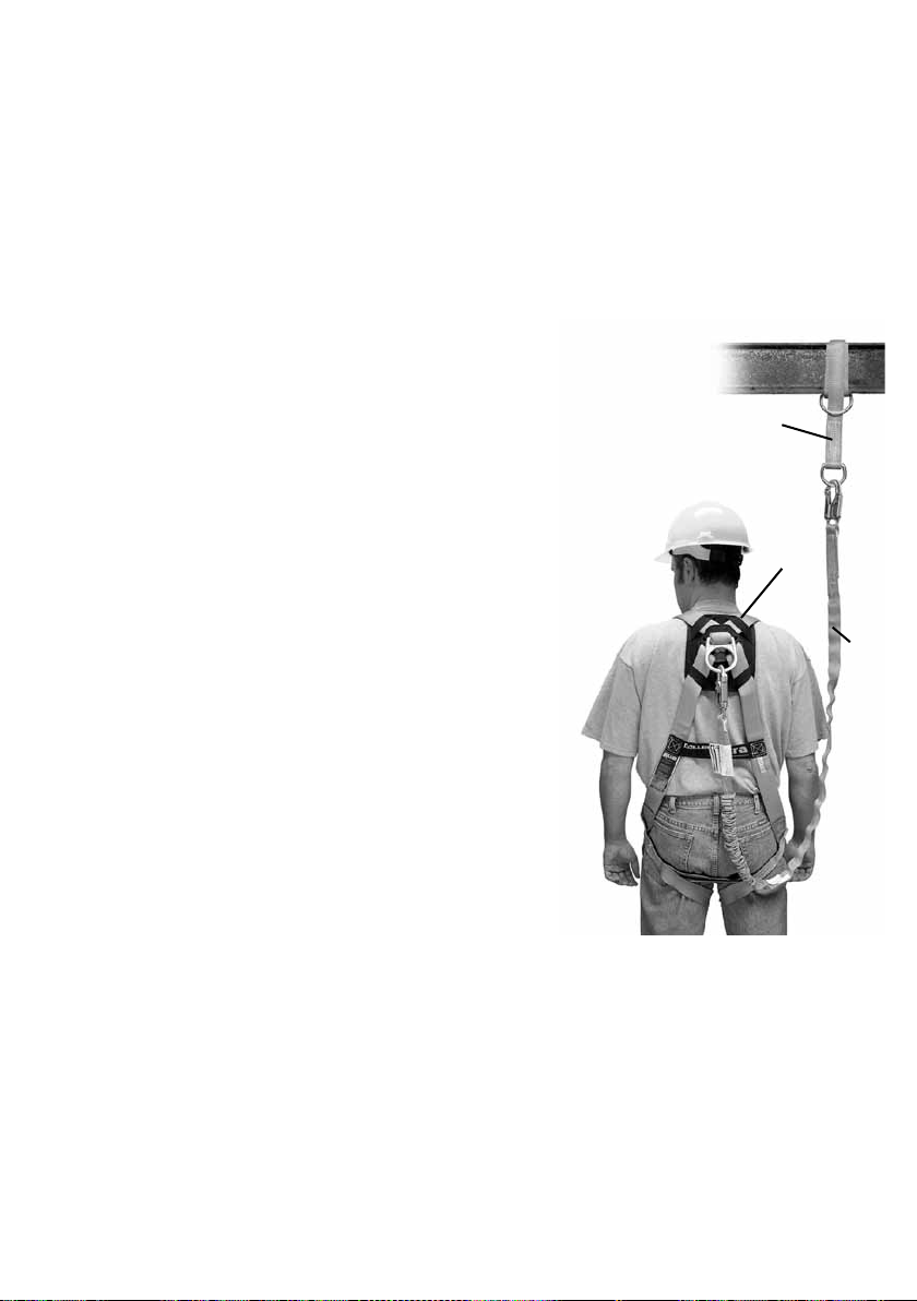
A
A. ANCHORAGE POINT
If possible, use structural anchors (conforming to EN 795), i.e.
items attached in a lasting manner to a structure (wall, post...)
In all cases check that the anchorage point is:
• Oers resistance of more than 10 KN,
• Is situated above the operator
• Is in a vertical axis to the work surface: (maximum angle ± 30°),
• Is totally suitable for the equipment anchorage device.
• Has no sharp edges.
B. BODY WEAR
The second system component is the personal protective gear
worn by workers while performing the job. Miller by Sperian
manufactures full-body harnesses, positioning belts and body
belts for use in specic work environments. Full-body harnesses
are engineered to aid in the arrest of a free fall and should be
worn in all situations where workers are exposed to a potential
free fall. The full-body harness must be used in conjunction with
shock-absorbing equipment to keep fall forces to a minimum. It is
imperative that the harness be worn properly.
C. CONNECTING DEVICE
The third component of the system is the connecting device. The most important feature of the connecting device
is the built-in shock absorber. Whether the connecting device is a shock-absorbing lanyard or self-retracting lifeline,
they are designed to dramatically reduce
fall arresting forces. Rope, web or cable lanyards being used for fall arrest MUST be used in conjunction with a shock
absorber.
Individually, none of these components will provide protection from a fall. Used properly with each other, they
form the “Miller System” and become a critically important part of the “total fall protection system.”
B
C
3.2 TYPES OF CONNECTORS (EN 362:2004)
Class A: anchor connectors; component designed to be linked directly to a specic type of anchor
Class B: basic connectors: ‘intended to be used as a component
Class M. multi-use connectors: component Which may be Loaded in the major and Minor axis
Class T: termination connectors element of a sub-system in which the loading acts on a predetermined direction
Class Q: screw gate connectors: intended to be used only for enduring or permanent connections The class Identica-
tion is marked on the device.
10
Page 11
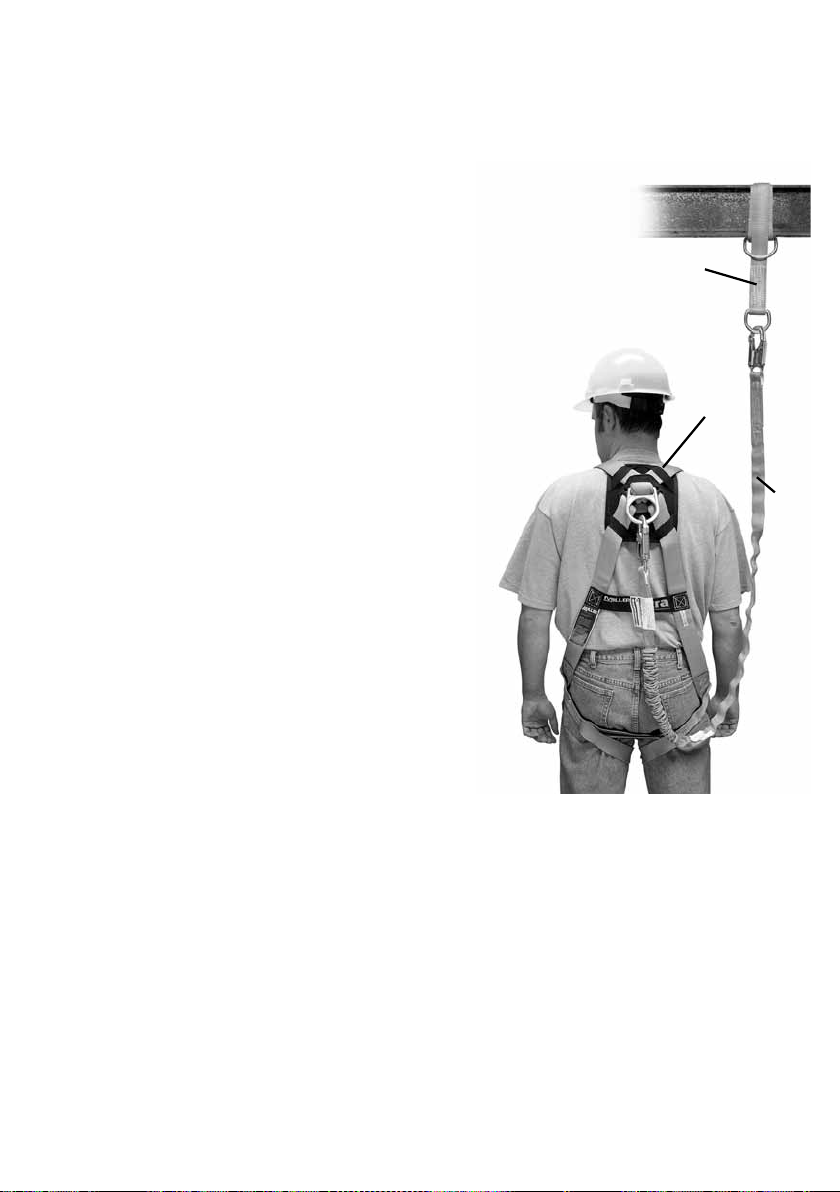
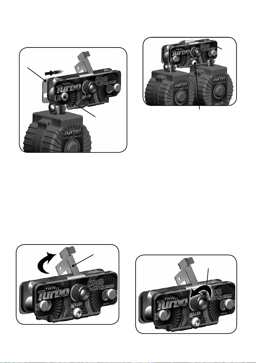
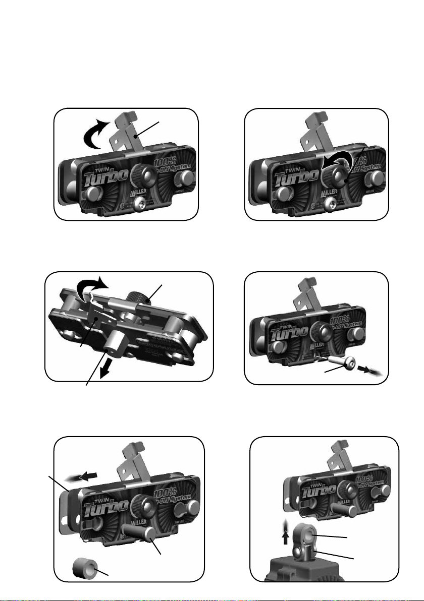
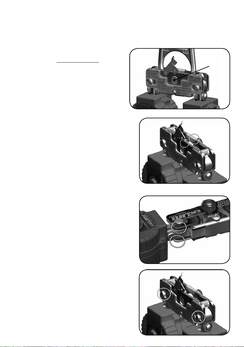
4.0 Assembling D-Ring Connector to TurboLite Units
WARNING: An authorized person should perform installation of TurboLite units into the D-Ring Connec-
tor. All Miller Self-Retracting Lifelines must be inspected and tested before each use (see 6.0 Inspection and
Step 1
Rotate D-Ring Pin Retainer Clockwise
to the fully open position.
D-Ring Pin
Retainer
Maintenance).
Step 2
Rotate D-Ring Pin Knob
Counter-Clockwise
until D-Ring Pin is free to move.
D-Ring Pin
Knob
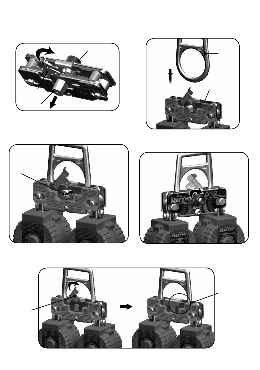
(a) Tilt D-Ring Connector back to allow D-Ring Pin
to slide clear of the D-Ring Slot.
(b) Rotate D-Ring Pin Retainer against D-Ring Pin
D-Ring Pin
Retainer
D-Ring Pin
to hold in place.
B.
A.
D-Ring Pin Knob
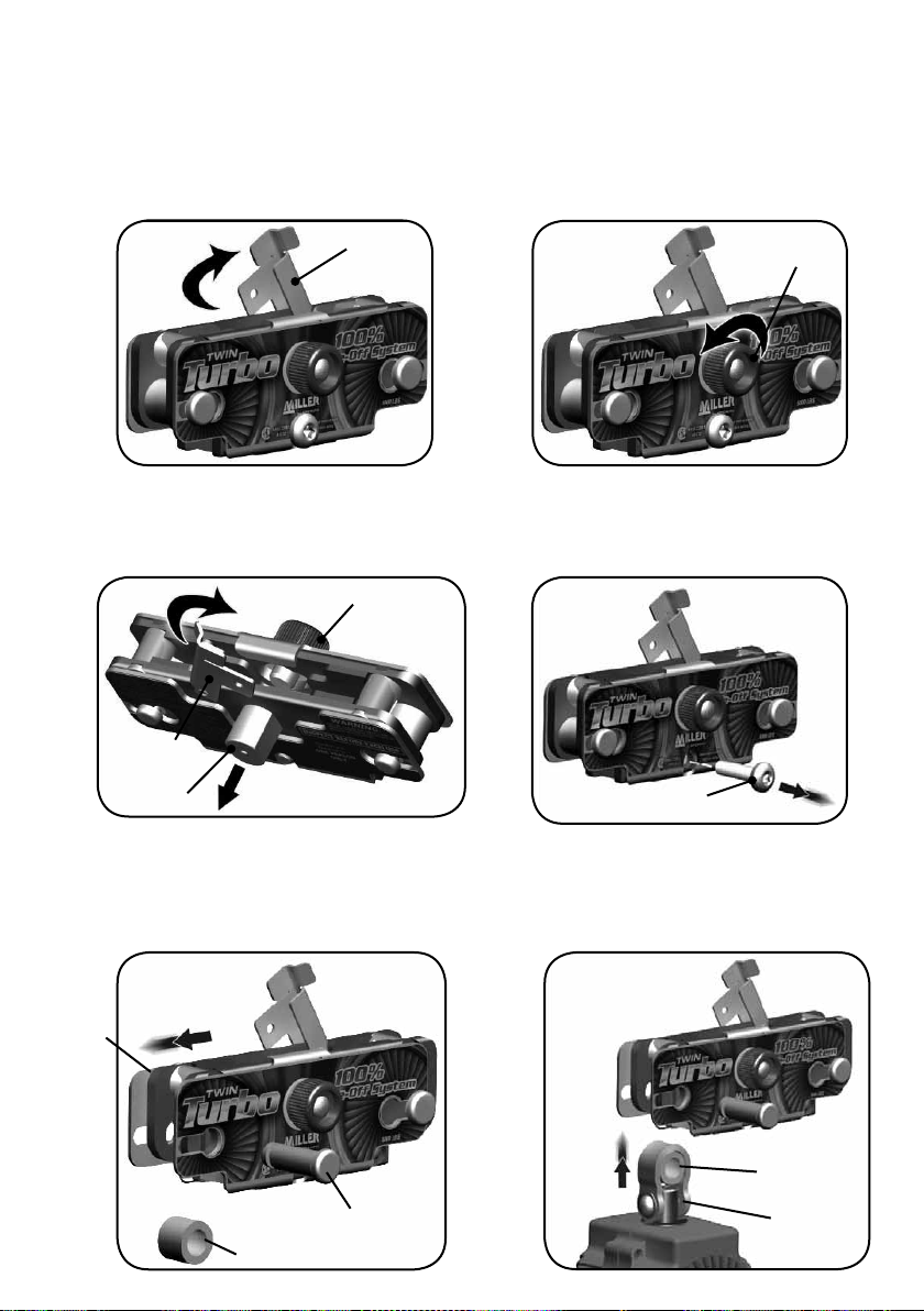
Step 5
(a) Slide Outer Frame to one side as shown.
(b) Remove PFL Retainer Pin and PFL Spacer
and set aside.
Step 3
Outer
Frame
A.
Remove Slide Lock Bolt using a 5/32”
Step 4
Hex wrench and set aside.
Slide Lock Bolt
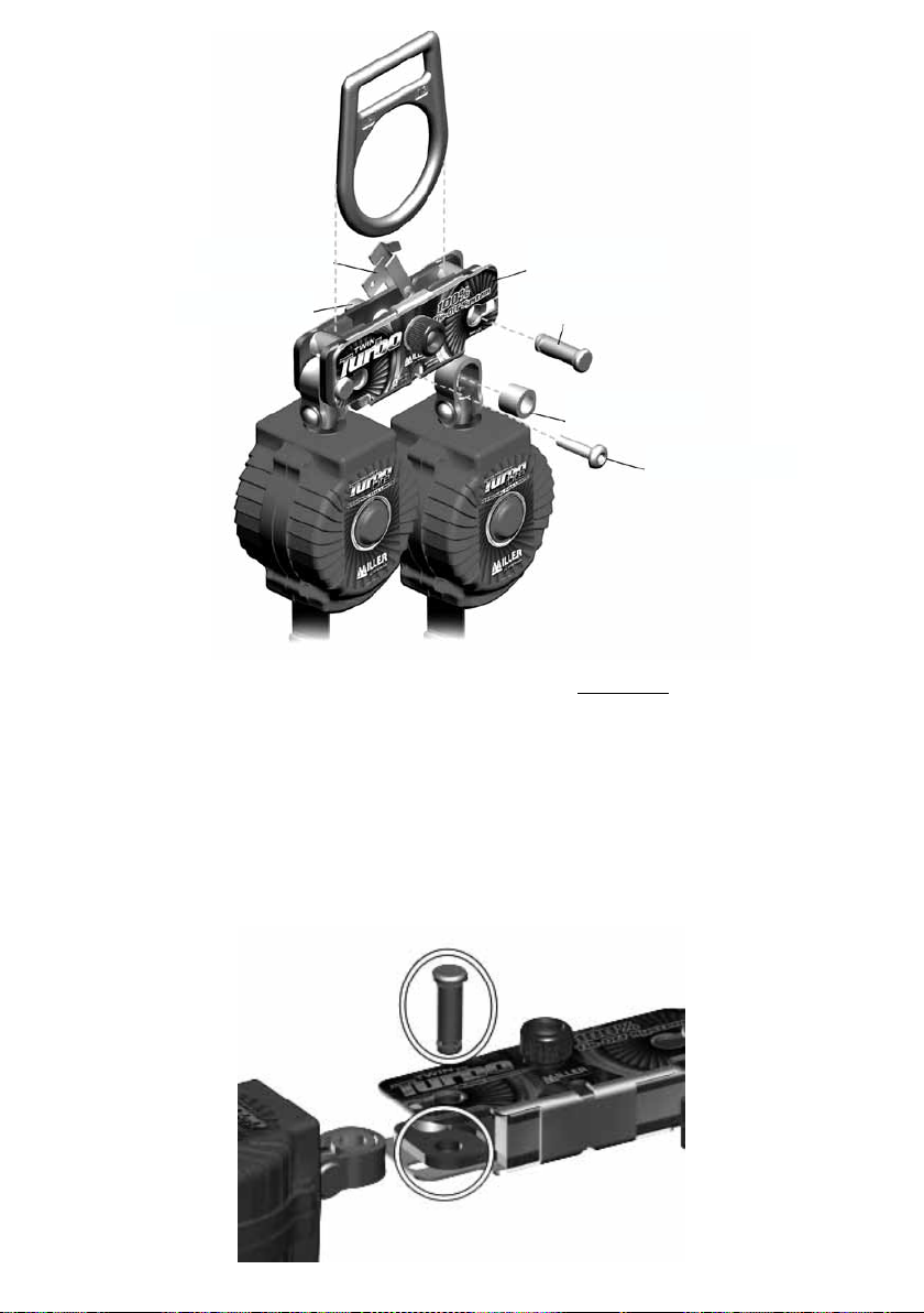
Step 6
Install PFL Spacer into TurboLite Swivel Loop
and place into slot in D-Ring Connector.
B.
PFL Spacer
PFL
Retainer Pin
PFL Spacer
TurboLite
Swivel Loop
11
Page 12
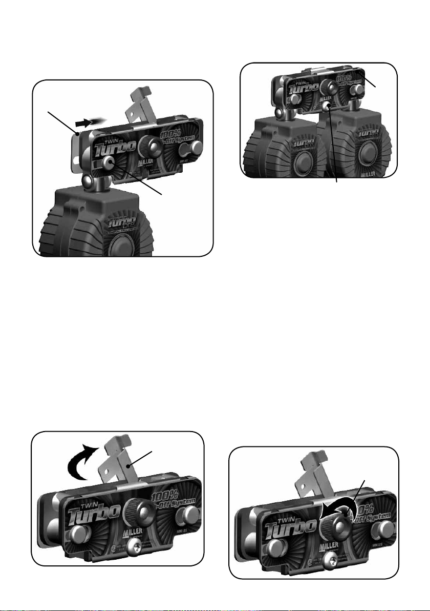
(a) Align PFL Spacer and TurboLite Swivel Loop and push
Step 7
PFL Retainer Pin until head contacts Outer Frame.
(b) Slide Outer Frame to center position to
engage PFL Retainer Pin.
Outer
Frame
B.
To install the other TurboLite Unit, repeat steps
Step 8
5-7, sliding Outer Frame in the opposite direction.
Outer
Frame
PFL
Retainer Pin
A.
Reverse Steps 1-3 to secure D-Ring Pin
and D-Ring Pin Retainer.
Slide Lock Bolt
Step 9
Step 10
Install Slide Lock bolt with a Hex wrench
and tighten to approx 10 ft-lbs. (reverse of Step 4)
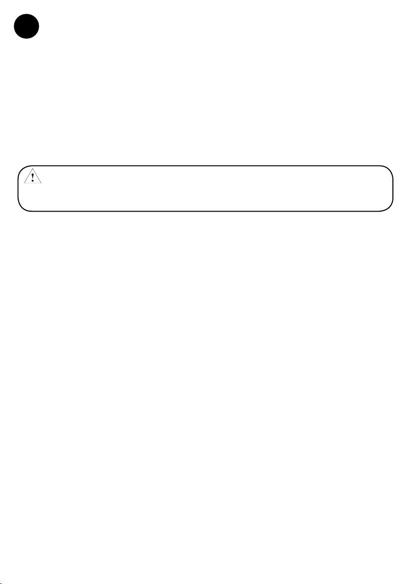
5.0 Attachment to Back D-ring
WARNING: This device must only be worn on the back D-ring and is not compatible with
web-loop back D-rings.
Rotate D-Ring Pin Retainer Clockwise
Step 1
to the fully open position.
Rotate D-Ring Pin Knob Counter-Clockwise
Step 2
until D-Ring Pin is free to move.
D-Ring Pin
Retainer
D-Ring Pin
Knob
12
Page 13
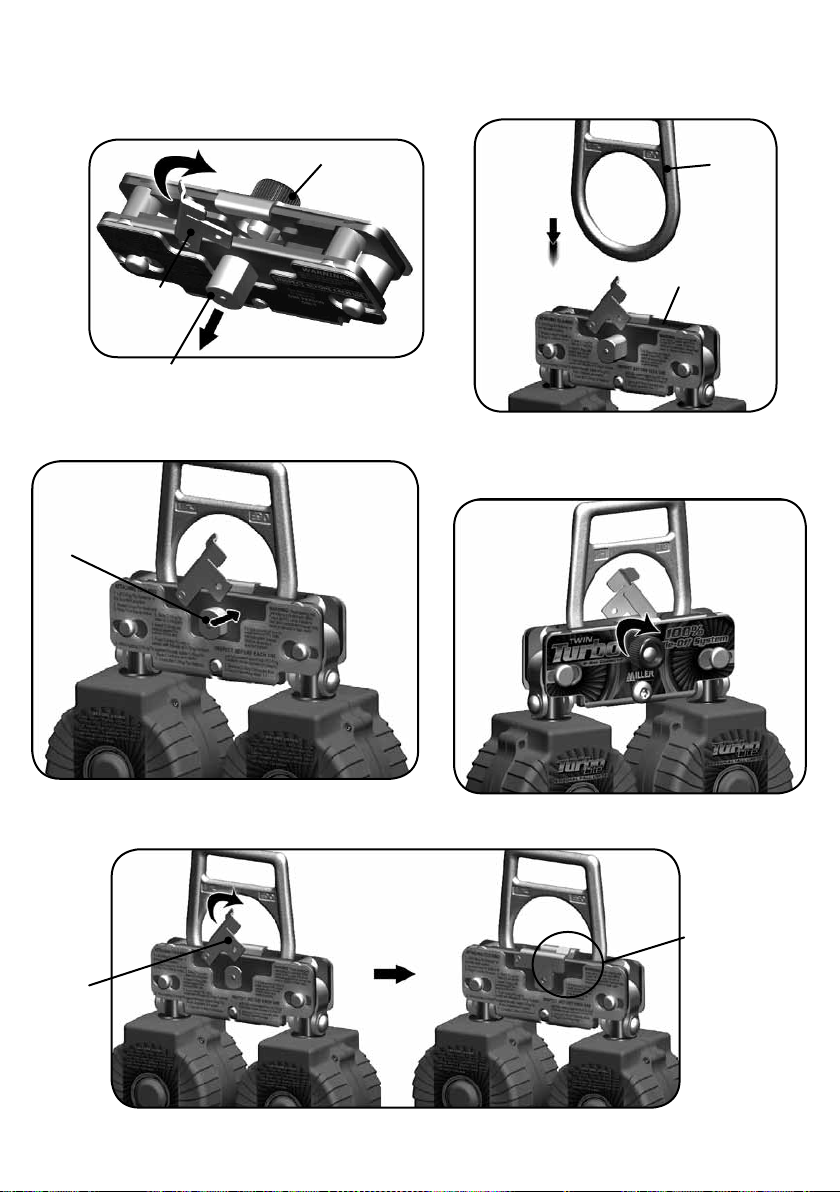
(a) Tilt D-Ring Connector back to allow D-Ring Pin
Step 3
to slide clear of the D-Ring Slot.
(b) Rotate D-Ring Pin Retainer against D-Ring Pin
to hold in place.
B.
D-Ring Pin Knob
Insert Back D-ring into slot until fully engaged
Step 4
and seated against the bottom of the slot.
Back
D-Ring
D-Ring Pin
Retainer
D-Ring Pin
A.
Step 5
Push D-Ring Pin through D-Ring opening until in
contact with threads of D-Ring Pin Knob.
D-Ring Pin
Rotate D-Ring Pin Retainer Clockwise until fully seated against top of
D-Ring Connector. (should cover back of D-Ring Pin)
D-Ring Pin Slot
Step 6
While holding D-Ring Pin against threads,
rotate D-Ring Pin Knob Clockwise and tighten.
Step 7
D-Ring Pin
Retainer
TO REMOVE D-RING CONNECTOR FROM D-RING, REVERSE STEPS 1-7.
WARNING:
Do not use
unless D-Ring
Pin Retainer is
fully closed.
13
Page 14
6.0 Inspection and Maintenance
6.1 Operation and Inspection
WARNING: UNITS THAT DO NOT PASS INSPECTION OR HAVE BEEN SUBJECTED
TO FALL ARRESTING FORCES MUST BE REMOVED FROM SERVICE.
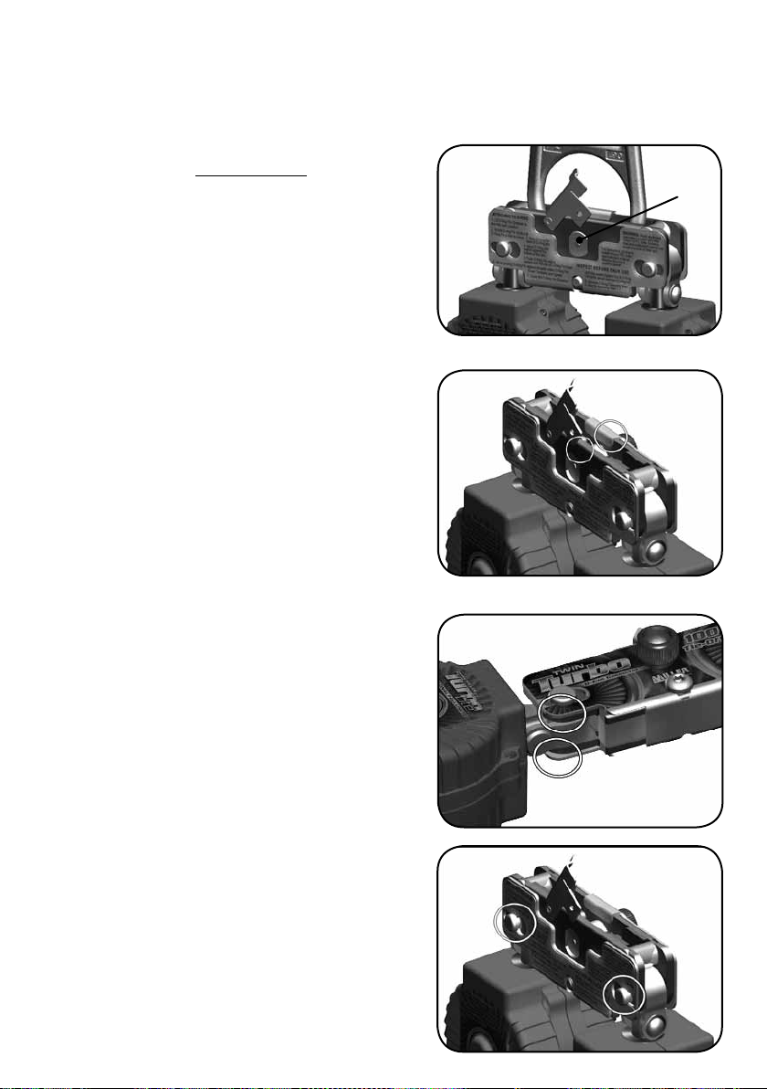
6.1.0 The following operation checkpoints and
inspections must be done prior to each use.
1. D-Ring Pin:
a. Inspect for cracks, splits. Remove from service if present.
b. D-Ring Pin must be approximately ush with the back of
the Inner Frame.
Flush
D-Ring Pin
2. D-Ring Pin Retainer:
Retainer must stay covering the end of the D-Ring Pin when in the
closed position.
Inspect for cracks or splits.
3. Inner Frame:
a. Areas over D-Ring Pin must be free of cracks, splits or stretched
material.
b. Inspect area around PFL Retainer Pins. Must be free of cracks,
splits or stretched material.
c. Side Plates and spacers must be secure with no play or
movement relative to each other.
4. Outer Frame:
Inspect areas around PFL Retainer Pins on both sides of Outer
Frame. Remove from service if distortion or material is removed
and no longer contains PFL Retainer Pins within Inner Frame
3a
3b
4
14
Page 15
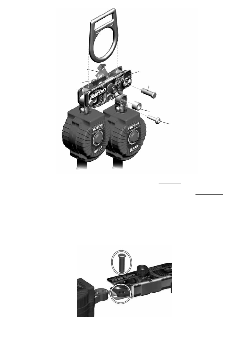
6.1.1 The following operation checkpoints and inspections must be done every year.
NOTE: ALL INSPECTIONS FOR “PRIOR TO EACH USE” IN SECTION 6.1.0 MUST BE PERFORMED IN ADDITION TO
THIS PROCEDURE.
1. Remove Turbolite units from the D-Ring Connector per the instructions in Section 4 of this manual.
2. Inspect PFL Retainer Pins and Areas around Pin Retainer holes in Inner Frame for cracks, splits.
3. Clean inner workings using compressed air, or bristle brush to remove any debris.
4. Install Turbolite units back into D-Ring Connector per Section 5 of this manual.
15
Page 16

7.0 Maintenance and storage
Good maintenance and appropriate storage of your PPE MI prolong the working-life of your product, while guaranteeing your safety.
Be sure to comply with these recommendations:
• Cleaning: Clean in water with a mild soap Never use add or alkali solvents
• Drying: allow to dry in a well-ventilated place away from any direct ame or any other source of heat.
• Lubrication: Lubricate the moving parts with a silicon-based lubricant Lubrication is carried out after the cleaning
and drying of the product
• Disinfection: Immerse the connector for an hour in a solution of tepid water and disinfectant used on quaternary
ammonium salts. Rinse in potable water and wipe with a dean loth.
• Storage: After cleaning, drying and lubricating, store the unpacked pro dud in a dry and cool place away rm sharp
edges and chemical or corrosive products.
Keep the connector away from UV light, direct or excessively strong sources of heat and too much relative humidity.
Avoid using the product in a dirty environment and never put it away when it is wet.
7.1 Periodic inspection
These instructions must be kept with the product. Use the identication card for recording the labelling information.
The periodic inspection shall check the equipment’s eectiveness and strength and is essential to guarantee the user’s
safety. The PPE must be inspected at least once a year by the manufacturer or by an authorized person and the inspection must be logged in the identication card. The frequency of inspection must be increased according to regulations,
in case of frequent use or use in harsh environmental conditions. The legibility of the product labelling must be checked.
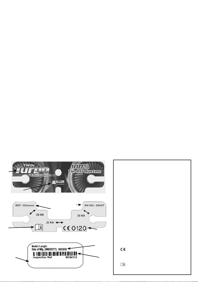
8.0 Product Label
3
1
9
6
Material: Aluminium/Stainless steel
16
2
102xxxxx
MEANING OF LABELING
1-The name, brand or any other ways of
identifying the manufacturer or the
supplier
2-The pro duct reference
3-The product designation
7
8
4
5
4-The date of manufacture (week/year)
5-The lot or serial number
6-The material(s) of the compo nents of the
equipment
7-EN xxx:xxxx: Number of the European
conformity standards and their years Class
T: termination connectors: element of a
sub-system in which the loading acts on a
predetermined direction
8-
0120 : EC logo followed by the number
of the organization notied to monitor the
production.
9-
: The standard pictogram indicating to
the user to read the documentation
Page 17

F
MILLER TWIN TURBO
Conformes à la norme EN362: 2004
Instructions D’utilisation - Français
Merci
Nous désirons vous remercier d’avoir acheté un équipement de Miller Fall Protection. Les produits de
marque Miller sont fabriqués selon des normes de qualité des plus rigoureuses, dans notre usine certiée
ISO 9001:2000. Bien entretenu, un équipement Miller Fall Protection s’utilise des années durant.
AVERTISSEMENT
Toutes les personnes qui utilisent cet équipement doivent lire, comprendre et suivre toutes les instructions. Tout
manquement à cette règle peut avoir pour conséquence des blessures graves ou la mort. Ne pas utiliser cet équipement à moins d’avoir reçu une formation adéquate
Des Questions? APPELEZ 02.48.52.40.42
Il est essentiel que la personne autorisée à utiliser cet équipement de protection contre les chutes lise et comprenne
ces instructions. De plus, il incombe à l’employeur de s’assurer que tous les utilisateurs sont formés à l’emploi, à
l’inspection et à l’entretien adéquats de l’équipement de protection contre les chutes. La formation sur la protection
contre les chutes devrait faire partie intégrante d’un programme global de sécurité.
L’utilisation adéquate de systèmes d’arrêt de chute peut épargner des vies et réduire le risque de blessures graves
consécutives à une chute. L’utilisateur doit être sensibilisé au fait que les forces subies lors d’un arrêt de chute
ou d’une suspension prolongée peuvent causer des blessures corporelles. Dans l’incertitude sur la capacité de la
personne à utiliser ce produit, consulter un médecin. Les femmes enceintes et les mineurs ne doivent pas utiliser ce
produit.
1.0 Objet
Les câbles de sécurité autorétractables de Miller, y compris les limiteurs de chute et les sangles rétractables,
sont des dispositifs rétractables indépendants conçus pour être utilisés par le personnel dans
des situations qui exigent une protection contre les chutes ainsi qu’une mobilité totale de l’ouvrier
2.0 Exigences Générales
2.1 Mises en Garde Générales
Les avertissements et instructions devront être mis à la disposition des personnes/utilisateurs autorisés.
Les personnes/utilisateurs autorisés doivent se reporter à la réglementation applicable en matière de sécurité en milieu
de travail, ainsi qu’aux normes CE pertinentes.
Des précautions doivent être prises an d’éliminer de la zone de travail les obstacles, débris, matériaux ou autres élé-
ments présentant un danger et qui pourraient causer des blessures ou nuire au bon fonctionnement du système.
L’équipement doit être inspecté avant chaque utilisation selon les directives du fabricant.
L’équipement doit être régulièrement inspecté par une personne qualiée.
Pour minimiser le risque de décrochage accidentel, une personne compétente doit s’assurer de la compatibilité du
système.
Il est interdit de modier l’équipement, de quelque façon que ce soit.
Les réparations doivent être eectuées uniquement par le fabricant de l’équipement, ou par des personnes ou entités
autorisées par écrit par le fabricant.
Tout produit déformé, anormalement usé ou détérioré doit être immédiatement mis au rebut.
Tout équipement soumis à une chute doit être mis hors service.
17
Page 18

L’utilisateur doit posséder un plan de sauvetage et avoir les moyens de le mettre en oeuvre lorsqu’il utilise cet équipement.
Ne jamais utiliser un équipement de protection contre les chutes dans un but autre que celui pour lequel il a été
prévu. Ne jamais utiliser un tel équipement pour remorquer ou lever une charge.
Les matériaux synthétiques doivent être protégés contre le laitier (de soudure), les étincelles chaudes, les ammes
nues ou autres sources de chaleur. Dans de tels cas, on recommande d’utiliser des matériaux résistant à la chaleur.
Dans la sélection d’équipement de protection contre les chutes, on doit tenir compte des risques environnementaux. On ne doit pas exposer l’équipement aux produits chimiques susceptibles de causer un eet nocif. Pour utiliser
l’équipement dans des environnements hautement corrosifs ou caustiques, il faut mettre en place un programme
d’inspection et d’entretien à intervalles rapprochés pour maintenir l’intégrité du dispositif. En cas de doute, communiquer avec les services techniques de Miller
Éviter tout contact entre un équipement et un objet susceptible de l’endommager, incluant notamment, sans que
la liste soit exhaustive : des arêtes vives, une surface abrasive, rugueuse ou à haute température, du matériel de soudage, une source de chaleur, un appareil électrique présentant un danger ou une machine mobile.
Toujours vérier qu’il n’y a pas d’obstacles en dessous de la zone de travail et que le trajet en cas de chute est dégagé.
Éviter les risques de chute par balancement en travaillant directement en-dessous du point d’ancrage.
Prévoir une distance de dégagement susante en dessous de la surface de travail.
Ne jamais ôter une étiquette apposée sur un produit; des informations et avertissements importants y sont en eet
inscrits à l’intention de la personne/de l’utilisateur autorisé.
2.2 Avertissements et Limitations
À utiliser par UNE SEULE personne.
Ne pas utiliser le dispositif s’il ne se rétracte pas.
Le dispositif doit être soumis à des tests de verrouillage avant chaque usage.
Les antichutes à rappel automatique doivent être retirés du service si une partie quelconque du système
semble endommagée ou ne passe pas l’inspection, ou si le dispositif a subi des contraintes d’arrêt
de chute.
Ne pas tenter de réparer ce dispositif. Si un antichute à rappel automatique ne fonctionne pas comme il faut
ou nécessite des réparations, retourner le dispositif au fabricant de l’équipement ou au centre d’entretien
autorisé par écrit par le fabricant, pour les réparations voulues. [ Les dispositifs qui ne passent pas l’inspection
et qui ne sont pas réparables doivent être éliminés comme il se doit. ]
Ne pas lubrier ce dispositif.
Le dispositif doit être tenu propre et exempt de contaminants.
Le dispositif doit être installé et utilisé de manière à réduire au minimum le risque d’une chute par
balancement.
Ne jamais travailler au-dessus du dispositif, à moins que ce dernier soit installé pour être utilisé dans une
structure ( par ex. montecharge, conformément aux instructions d’installation ).
Ne jamais utiliser le dispositif comme un dispositif de contrainte ou de positionnement.
18
Page 19
3.0 Compatibilité du Système
Les antichutes à rappel automatique Miller by Sperian sont conçus pour être utilisés en conjonction avec des composants approuvés par Miller. Les substitutions ou les remplacements par des combinaisons de composants ou de
sous-systèmes non approuvés peuvent nuire à leur sécurité de fonctionnement réciproque et ainsi remettre en cause
la compatibilité des éléments du système. Cette incompatibilité peut nuire à la sécurité et à la abilité de l’ensemble
du système.
3.1 Groupes de Produits Miller Fall Protection
Un programme complet de protection contre les chutes doit être considéré comme un « système total », débutant par
une identication des risques et se terminant par une revue de la direction; cette revue doit avoir lieu en permanence.
Pour Miller by Sperian , ces produits représentent un « système dans un système ». Une protection maximale du travailleur passe par la mise en place et l’utilisation adéquate de trois composants clés du « système Miller ».
A. POINT D’ANCRAGE
Utiliser si possible des ancres structurelles (conforme à EN 795) c’est à
dire des éléments xés durablement sur une structure (mur. poteau...),
Vériez dans tous les cas que le point d’ancrage
• A une résistance minimum de 10KN
• Est situé au-dessus de l’operateur
•Se trouve dans l’axe vertical du plan de travail : (angle maxi ± 30°)
• S’adapte parfaitement au dispositif d’accrochage de l’équipement
• Ne présente pas d’arête tranchante.
A
B. ÉQUIPEMENT DE PROTECTION INDIVIDUELLE
L’équipement de protection individuelle porté par les travailleurs dans
l’accomplissement de leurs tâches constitue le second composant.
Miller by Sperian fabrique des harnais de sécurité complets, des
ceintures de maintien au travail et des ceintures de travail pour
utilisation dans des conditions (de travail) bien précises. Un harnais de
sécurité
complet est étudié pour l’arrêt d’une chute libre et doit être porté
par tout travailleur exposé à un risque de chute. Un harnais de sécurité
complet doit être utilisé en même temps qu’un absorbeur d’énergie
an de réduire au minimum les forces présentes en cas de chute. Il est
essentiel de porter le harnais de la bonne manière.
C. DISPOSITIF DE CONNEXION
Le dispositif de connexion constitue le dernier composant du système.
L’élément le plus important du dispositif de connexion est l’absorbeur
d’énergie incorporé. Que le dispositif soit une corde d’amarrage à absorbeur d’énergie ou un cordage de sécurité à rétraction automatique,
il a été conçu pour réduire substantiellement les forces mises en jeu lors
de l’arrêt d’une chute. Une corde d’amarrage constituée par une corde,
une sangle ou un câble et servant de dispositif antichute DOIT ÊTRE utilisé en même temps qu’un absorbeur d’énergie
.
Aucun de ces composants ne peut assurer à lui seul une protection contre les chutes. Utilisés comme un tout,
ces composants forment le « système Miller » et constituent une partie du « système total de protection contre
les chutes », système d’une importance vitale.
B
C
3.2 TYPE DE CONNECTEURS (EN 362: 2004)
Classe A: connecteur d’ancrage: conçu pour être relié directement à un type spécique d’ancrage
Classe B: connecteur de base: destiné à être utilisé comme composant
Classe M: connecteur multi-usages: qui peut être mis en charge selon son grand axe ou son petit axe
Classe T: connecteur terminal élément d’un sous-système où la charge s’exerce dans une direction prédéterminée
Classe Q: connecteur avec fermoir à vis destiné à être utilisé dans des applications à long terme ou permanentes
Le modèle de référence est marqué sur le dispositif.
19
Page 20
4.0 Assemblage du raccord de l’anneau en D aux éléments TurboLite
MISE EN GARDE: L’installation des éléments TurboLite dans le raccord de l’Anneau en D doit être eectuée
par une personne compétente. Tous les câbles de sécurité Miller doivent être inspectés et mis à l’essai avant
Faire pivoter le xe-goupille de l’anneau en D dans le
sens horaire jusqu’à la position totalement ouverte.
chaque usage (voir 6.0 Inspection et maintenance).
Étape 1
Fixe-
goupille
d’anneau en D
Faire pivoter la poignée de goupille de l’anneau
en D dans le sens anti-horaire jusqu’à ce que la
goupille de l’anneau en D puisse bouger librement.
Étape 2
Poignée de
goupille
d’anneau en D
a) Faire basculer le raccord d’anneau en D pour
permettre à la goupille de se dégager de la fente de l’anneau.
b) Faire pivoter le xe-goupille de l’anneau en D contre
la goupille pour le retenir en place.
B.
Fixe-goupille
de l’anneau
en D
Goupille de l’anneau en D
A.
Poignée de
goupille de
l’anneau en D
Étape 5
a) Faire glisser le cadre extérieur d’un côté, tel qu’illustré.
b) Retirer la goupille de retenue PFL et l’entretoise
PFL et mettre de côté.
Étape 3
Cadre
extérieur
A.
Retirer le boulon de serrage à l’aide d’une clé
Étape 4
hexagonale de 5/32 po et mettre de côté
Boulon de verrouillage à glissière
Étape 6
Poser l’espacement PFL dans la boucle
articulée TurboLite et la placer dans la fente du
raccord de l’anneau en D.
20
B.
Espacement PFL
Goupille de
retenue PFL
Espacement
PFL
Boucle
articulée
TurboLite
Page 21
a) Aligner l’espacement PFL et la boucle articulée
Étape 7
TurboLite et pousser la goupille de retenue PFL jusqu’à
ce que la tête entre en contact avec le cadre extérieur.
b) Faire glisser le cadre extérieur à la position centrale
pour engager la goupille de retenue PFL.
Pour poser l’autre appareil TurboLite, reprendre
Étape 8
les étapes 5-7, en faisant glisser le cadre extérieur
dans la direction opposée.
Cadre
extérieur
B.
Goupille de
retenue PFL
A.
Boulon de verrouillage à glissière
Étape 9
Inverser les étapes 1-3 pour bien xer la
goupille de l’anneau en D et le xe-goupille.
Cadre
extérieur
Étape 10
Poser le boulon de verrouillage à glissière à l’aide
d’une clé hexagonale et serrer jusqu’à approximative-
ment 10 pi-lb (ordre inverse de l’étape 4).
5.0 Attache à l’anneau dorsal en D
MISE EN GARDE: Ce dispositif ne doit être porté que sur l’anneau dorsal en D et n’est pas compatible avec
les anneaux dorsaux en D de boucle en textile.
Faire pivoter le xe-goupille de l’anneau en D dans le
Étape 1
sens horaire jusqu’à la position totalement ouverte.
Fixe-
goupille
d’anneau en D
Faire pivoter la poignée de goupille de l’anneau
Étape 2
en D dans le sens anti-horaire jusqu’à ce que la
goupille de l’anneau en D puisse bouger librement.
Poignée de
goupille
d’anneau en D
21
Page 22
a) Faire basculer le raccord d’anneau en D pour
Étape 3
permettre à la goupille de se dégager de la fente de l’anneau.
b) Faire pivoter le xe-goupille de l’anneau en D contre
la goupille pour le retenir en place.
B.
Poignée de
goupille de
l’anneau en D
Insérer l’anneau dorsal en D dans la fente
Étape 4
jusqu’à ce qu’il soit totalement engagé et qu’il
repose au fond de la fente.
Anneau
dorsal en D
Fixe-goupille
de l’anneau
en D
Goupille de l’anneau en D
A.
Étape 5
Pousser la goupille de l’anneau en D à travers l’ouverture
de l’anneau en D jusqu’à ce qu’elle entre en contact avec
le letage de la poignée de goupille de l’anneau en D.
Goupille de
l’anneau en D
Étape 7
Faire pivoter le xe-goupille de l’anneau en D dans le sens horaire jusqu’à ce qu’il s’appuie
totalement sur le dessus du raccord de l’anneau en D. (doit couvrir l’arrière de la goupille)
Fente de l’anneau
en D
Étape 6
En tenant la goupille de l’anneau en D contre le
letage, faire pivoter la poignée de goupille de l’anneau
en D dans le sens horaire et serrer.
MISE EN GARDE:
Ne pas utiliser à
Fixegoupille
de l’anneau
en D
POUR RETIRER LE RACCORD DE L’ANNEAU EN D DE L’ANNEAU EN D, INVERSER LES
ÉTAPES 1-7.
22
moins que le
xegoupille
de l’anneau
en D soit
complètement
fermé.
Page 23
6.0 Inspection et maintenance
6.1 Fonctionnement et inspection
MISE EN GARDE: LES ÉLÉMENTS QUI NE RÉUSSISSENT PAS À L’INSPECTION
OU QUI ONT ÉTÉ SOUMIS À DES FORCES D’ARRÊT DE CHUTE DOIVENT ÊTRE
RETIRÉS DU SERVICE.
6.1.0 Les vérications et inspections suivantes
doivent être eectuées avant chaque usage.
1. Goupille d’anneau en D:
a. Vérier la présence de ssures ou de crevasses.
Dans le cas de l’armative, retirer du service.
b. La goupille de l’anneau en D doit être à peu près
en aeurement avec l’arrière du cadre intérieur.
Goupille
d’anneau en D
en aeurement
2. Fixe-goupille d’anneau en D:
Le xe-goupille doit couvrir l’extrémité de la goupille de l’anneau
en D lorsqu’il est en position fermée. Vérier la présence de ssures
ou de crevasses.
3. Cadre intérieur:
a. Les sections au-dessus de la goupille de l’anneau en D doivent
être libres de ssures, crevasses ou de matériel étiré.
b. Inspecter la région autour des goupilles de retenue PFL. Elles
doivent être exemptes de ssures, crevasses ou de matériel étiré.
c. Les plaques et espacements latéraux doivent être bien xés, sans
jeu ni mouvement les uns par rapport aux autres.
4. Cadre extérieur:
Inspecter les régions autour des goupilles de retenue PFL des deux
côtés du cadre extérieur. Retirer du service en cas de distorsion ou
de matériel enlevé et s’il ne renferme plus des goupilles de retenue
PFL à l’intérieur du cadre intérieur.
3a
3b
4
23
Page 24
Fixe-goupille
d’anneau en D
Goupille
d’anneau en D
6.1.1 Les vérications et inspections suivantes doivent être eectuées tous les ans
NOTA: TOUTES LES INSPECTIONS POUR « AVANT CHAQUE USAGE » À LA SECTION 6.1.0 DOIVENT ÊTRE
EFFECTUÉES EN PLUS DE CETTE PROCÉDURE.
1. Retirer les appareils Turbolite du raccord de l’anneau en D selon les instructions gurant à la Section 4 du présent
manuel.
2. Inspecter les goupilles de retenue PFL et les régions autour des trous du xe-goupille dans le cadre intérieur pour y
détecter des ssures ou des crevasses.
3. Nettoyer les mécanismes internes à l’aide d’air comprimé, ou d’une brosse en soies pour enlever tout débris.
4. Replacer les appareils Turbolite dans le raccord de l’anneau en D selon la Section 5 du présent manuel.
Cadre extérieur
Goupille de retenue
PFL
Espacement PFL
Boulon verrouillant
à glissière
24
Page 25
7.0 Entretien et stokage
Un bon entretien ainsi qu’un stockage adéquat de votre EPi assureront une meilleure longévité au produit tout en
garantissant votre sécurité.
Veillez à respecter strictement ces recommandations:
• Nettoyage : nettoyez le à l’eau et au savon doux. N’utilisez en aucun cas des solvants acides ou des bases.
• Séchage: laissez-le sécher dans un endroit ventilé et à distance de tout feu direct ou de toute autre source de
chaleur.
• Lubrication lubriez les parties mobiles avec un lubriant à base de silicone. La lubrication s’eectue après le
nettoyage: et le séchage du produit.
• Désinfection : immergez le connecteur pendant une heure dans une solution d’eau tiède et d’un désinfectant à
Base de sels d’ammonium quaternaires. Rincez à l’eau potable et essuyez avec un chion propre.
• Stockage : après nettoyage, séchage et lubrication, ranger le produit déballé dans un endroit sec et frais, loin de
tout objet tranchant et de tout produit chimique ou corrosif. Conservez le connecteur à l’abri des rayons UV, des
sources directes ou excessives de chaleur et d’un taux trop élevé d’humidité. Évitez d’utiliser le produit dans un
environnement salé et ne le rangez pas mouillé.
7.1 Examen periodique
Ces instructions doivent être conservées avec le produit. Renseignez la che d’identication en reportant les informations du marquage. Cet examen périodique vériant l’ecacité et la résistance de l’équipement est indispensable an
de garantir la sécurité de l’utilisateur.
Cet EPI doit être examiné, au moins une fois par an, par le fabricant ou par une personne agréée, la vérication devant
être enregistrée sur la che d’identication. La fréquence d’examen doit être augmentée en fonction de la réglementation, dans le cas d’une utilisation importante ou dans des conditions environnementales diciles. La lisibilité des
marquages du produit devra être vériée.
8.0 Étiquettes de Produit
3
1
2
9
102xxxxx
6
Materiaux : Aluminium/Inox
SIGNIFICATION DU MARQUAGE
1-Le nom, la marque commerciale ou tout
autre moyen d’identication du fabricant
ou du fournisseur
2-La référence du produit
3-La désignation du produit
7
8
4
5
4-La date de fabrication (semaine /année)
5-Le numéro de lot ou le numérode série
6-Le ou les matériaux des composants de
l’équipement
7-EN xxx : xxxx : Numéro des normes
européennes de conformité et leur Année
Classe T : Connecteur terminal: élément
d’un sous système où la charge s’exerce
dans une direction pré-déterminée
8-
0120 : Logo CE suivi du n° de
l’organisme notié intervenant dans la
phase de contrôle de la production
9-
: Le pictogramme norma lisé indiquant
à l’utilisateur de lire la notice
25
Page 26

D
MILLER TWIN TURBO
EN362: 2004
Gebrauchsanleitung – Deutsch
Vielen Dank
Vielen Dank, dass Sie eine Fallschutzausrüstung von Miller gekauft haben. Die Miller-Markenprodukte werden in unserem nach ISO 9001:2000 zertizierten Werk entsprechend den höchsten Qualitätsstandards hergestellt. Wenn Sie die
Fallschutzausrüstung von Miller richtig pegen, werden Sie jahrelang Nutzen daran haben.
WARNUNG
Alle Personen, die diese Ausrüstung benutzen, müssen alle Anleitungen lesen, verstehen und befolgen. Die
Nichtbeachtung dieser Warnung kann zu ernsthaften Verletzungen oder zum Tod führen. Verwenden Sie
diese Ausrüstung nur, wenn Sie richtig geschult sind.
Noch Fragen? RUFEN SIE UNS AN: +33 (0)2.48.52.40.42
Der Befugte/der Verwender dieser Fallschutzausrüstung muss unbedingt die Anweisungen lesen und verstehen.
Außerdem muss der Arbeitgeber sicherstellen, dass alle Benutzer in der richtigen Verwendung, Inspektion und Pege
der Fallschutzausrüstung geschult werden. Fallschutztraining sollte integraler Teil eines umfassenden Sicherheitsprogramms sein. Die richtige Verwendung von Absturzsicherungssystemen kann Leben retten und potentielle ernsthafte
Verletzungen aufgrund eines Absturzes verhindern. Der Benutzer muss sich dessen bewusst sein, dass durch die Kräfte,
die während des Auangens eines Sturzes oder bei längerem Hängen auftreten, Körperverletzungen verursacht wer-
den können. Bitte wenden Sie sich an einen Arzt, wenn irgendwelche Bedenken bezüglich der Verwendung dieser
Ausrüstung durch einen bestimmten Benutzer bestehen. Schwangere Frauen und Minderjährige dürfen diesen Artikel
nicht verwenden.
1.0 Zweck
Höhensicherungsgeräte von Miller, inklusive Auanggeräte und Rückhalteseile, sind autonome Geräte für Arbeiter, die
bei uneingeschränkter Bewegungsfreiheit gegen Absturz gesichert werden müssen.
2.0 Allgemeine Anforderungen
2.1 Allgemeine Warnhinweise
Die Warnhinweise und Gebrauchsanweisungen müssen allen befugten Personen/Verwendern zur Verfügung gestellt
werden.
Alle befugten Personen/Verwender müssen sich über die Vorschriften zur Arbeitssicherheit informieren, ebenso über
die einzuhaltenden ANSI- oder CSA-Normen.
Im Vorfeld ist immer dafür zu sorgen, dass sich im Arbeitsbereich keine Hindernisse, Abfälle, Materialien oder andere
bekannte Gefahrenquellen benden, welche zu Verletzungen führen oder die Funktionsweise des Systems zur Absturzsicherung beeinträchtigen könnten.
Die gesamte Ausrüstung muss vor jeder Verwendung entsprechend den Herstelleranweisungen inspiziert werden.
Die gesamte Ausrüstung muss regelmäßig von einer fachkundigen Person inspiziert werden.
Um die Gefahr eines versehentlichen Loslösens zu minimieren, muss eine Fachperson die Kompatibilität des Systems
sicherstellen.
Die Ausrüstung darf in keiner Weise abgeändert werden.
Reparaturen dürfen nur vom Hersteller oder von Personen oder Organen ausgeführt werden, die dazu vom Hersteller
26
Page 27

schriftlich befugt sind.
Wenn ein Produkt Verformungen, ungewöhnliche Abnutzung oder Beschädigungen ausweist, muss es sofort ausran-
giert werden.
Ausrüstungsteile, die bei einem Sturz zum Einsatz kamen, müssen außer Betrieb genommen werden.
Die befugte Person/der Benutzer muss, wenn er diese Ausrüstung verwendet, einen Rettungsplan und die Mittel, um
diesen umzusetzen, zur Hand haben.
Fallschutzausrüstung darf ausschließlich für die Zwecke verwendet werden, für die sie konzipiert wurde. Fallschutzaus-
rüstung darf niemals für Zug- oder Hebevorgänge verwendet werden.
Alle synthetischen Materialien müssen vor (Schweiß-)Schlacke, Funken, oenen Flammen oder anderen Hitzequellen
geschützt werden. Für diese Verwendungszwecke wird die Benutzung hitzebeständiger Materialien empfohlen.
Bei der Auswahl von Fallschutzausrüstung sollten Umgebungsrisiken berücksichtigt werden. Die Ausrüstung darf nicht
mit Chemikalien in Kontakt kommen, die Schäden verursachen könnten. In bestimmten Umgebungen mit Chemikalien
oder Säuren sollte Polyester verwendet werden. Bei der Verwendung in hochgradig korrosiven oder ätzenden Umgebungen ist ein häugeres Inspektions- und Wartungsprogramm zwingend erforderlich, damit die Integrität des Geräts
gewährleistet bleibt. In allen Zweifelsfällen wenden Sie sich bitte an den Technischen Kundendienst von Miller.
Verhindern Sie auf jeden Fall, dass die Ausrüstung mit Dingen in Kontakt kommt, die sie beschädigen können, wie z.
B. – und nicht nur – scharfe, abrasive, raue oder heiße Oberächen, Schweißvorgänge, Hitzequellen, elektrische Risken
oder bewegliche Maschinen(-teile).
Prüfen Sie den Raum unterhalb des Arbeitsbereichs immer auf Hindernisse; vergewissern Sie sich, dass der Fallweg frei
ist.
Sorgen Sie für ausreichende Fallfreiheit unterhalb der Arbeitsäche.
Entfernen Sie niemals Produktetiketten; sie enthalten wichtige Warnhinweise und Informationen für die befugte Per-
son/den Benutzer.
2.2 Warnhinweise und Grenzen
Darf nur von EINER Person verwendet werden.
Das Gerät nicht verwenden, wenn es sich nicht einzieht.
Vor jeder Verwendung muss das Gerät auf Arretieren geprüft werden.
Höhensicherungsgeräte dürfen nicht mehr verwendet werden, wenn ein beliebiges Teil des Systems
beschädigt zu sein scheint oder eine Prüfung nicht besteht oder den Kräften beim Auangen eines Sturzes
ausgesetzt war.
Versuchen Sie nicht, dieses Gerät zu reparieren. Wenn ein Höhensicherungsgerät nicht korrekt funktioniert
oder repariert werden muss, geben Sie es zur Reparatur an den Hersteller der Ausrüstung oder an ein vom
Hersteller schriftlich befugtes Servicezentrum zurück. [Geräte, die eine Prüfung nicht bestehen und nicht
repariert werden können, müssen korrekt entsorgt werden.]
Schmieren Sie dieses Gerät nicht.
Das Gerät muss sauber und frei von Verunreinigungen gehalten werden.
Das Gerät muss so angebracht und verwendet werden, dass die Gefahr von Pendeleekten bei einem Absturz
so gering wie möglich ist.
Arbeiten Sie niemals oberhalb des Geräts. Ausnahme: Wenn es zur Verwendung innerhalb einer Struktur mon-
tiert wurde (z. B. Aufzüge, in Übereinstimmung mit den Montageanweisungen).
Verwenden Sie das Gerät nie als Rückhalteseil oder zur Arbeitsplatzpositionierung.
27
Page 28
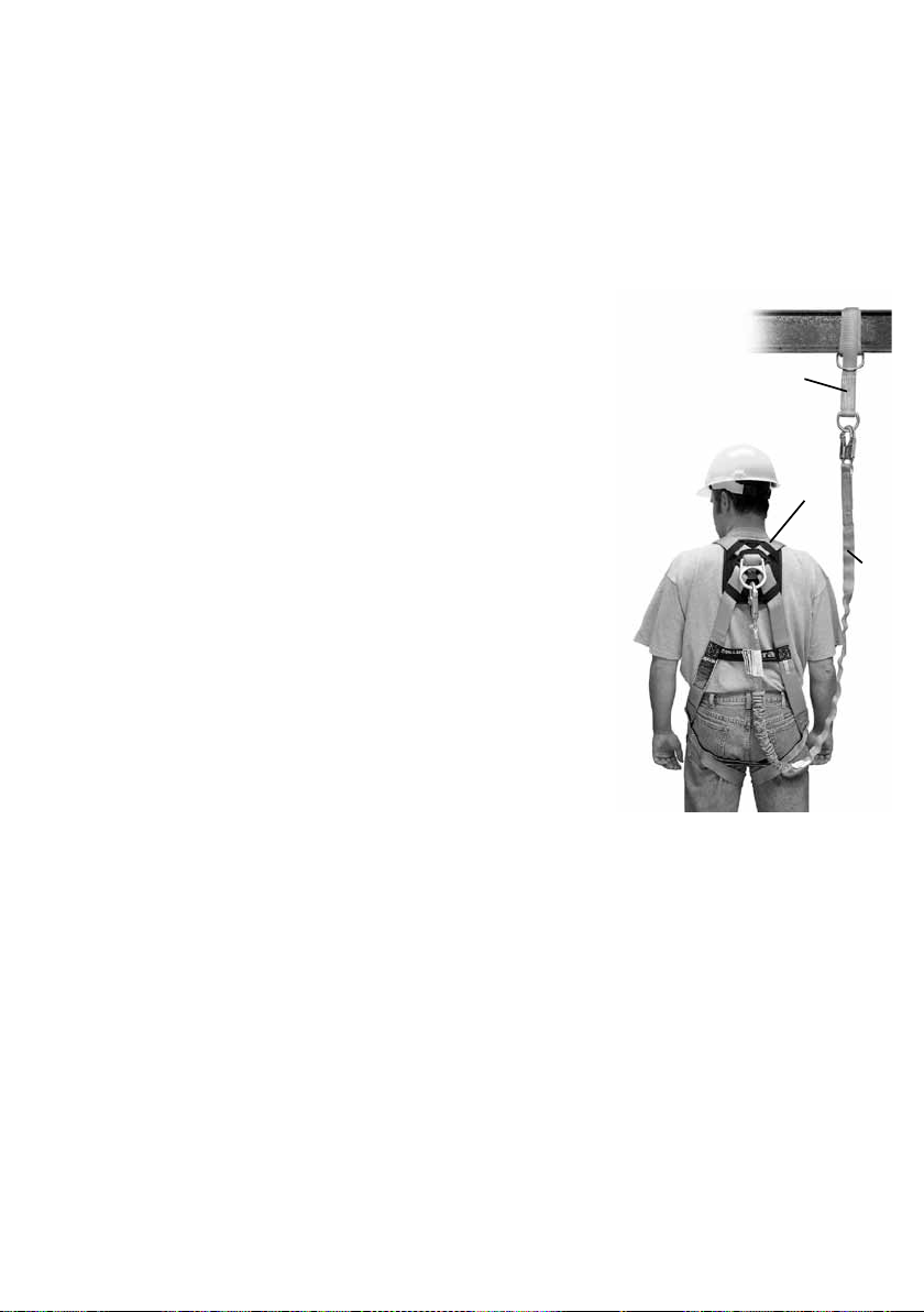
3.0 System-Kompatibilität
Miller Höhensicherungsgeräte sind für die Verwendung mit Komponenten konzipiert, die von Miller by Sperian zugelassen
sind. Ersatz oder Austausch durch eine nicht zugelassene Komponentenkombination oder durch ein Untersystem oder
sogar beides kann die jeweilige sichere Funktionsweise beeinträchtigen und der Kompatibilität innerhalb des Systems
schaden. Diese Inkompatibilität kann die Zuverlässigkeit und Sicherheit des gesamten Systems negativ beeinussen.
3.1 Produktgruppen Miller Fallschutz
Ein umfassendes Programm zur Absturzsicherung muss als ein „Gesamtsystem“ betrachtet werden, das mit der Identizierung der Gefahren beginnt und mit fortlaufender Überprüfung durch das Management schließt. Miller by Sperian
betrachtet seine Produkte als ein „System innerhalb eines Systems“. Um die Arbeiter bestmöglich zu schützen, müssen
drei Schlüsselkomponenten des “Miller-Systems” vorhanden sein.
A. ANSCHLAGPUNKT
Wenn möglich, Anschlagpunkte an Strukturen verwenden (gemäß EN 795), d.
h. dauerhafte Befestigung der Vorrichtungen an einer Struktur (Wand, Träger, ...)
Auf jeden Fall muss geprüft werden, dass der Anschlagpunkt
• einen Mindestwiderstand von 10 kN aufweist,
• sich oberhalb des Arbeiters bendet
• sich senkrecht zum Arbeitsplatz bendet (max. Neigung: ± 30°),
• sich uneingeschränkt für die Anschlagvorrichtung eignet
• Keine scharfen Kanten aufweist.
B. AUFFANGGURT
Die zweite Komponente des Systems ist die persönliche Schutzausrüstung, die
von den Arbeitern bei der Ausführung ihres Jobs getragen wird. Miller by Spe-
rian stellt Ganzkörper-Auanggurte, Haltegurte und Körpergurte für Einsätze in
bestimmten Arbeitsumgebungen her. Ganzkörper-Auanggurte sind so gestaltet, dass sie einen freien Fall aufhalten, und sie sollten in allen Situationen
getragen werden, in denen für Arbeiter die Gefahr eines freien Falls besteht. Der
Ganzkörper-Auanggurt muss in Verbindung mit einem Falldämpfer verwendet
werden, damit die Fallkräfte so weit wie möglich minimiert werden. Das Gurtzeug muss korrekt getragen werden.
C. VERBINDUNGSMITTEL
Die dritte Komponente des Systems ist das Verbindungsmittel. Die wichtigste
Eigenschaft des Verbindungsmittels ist die eingebaute Falldämpfung. Ob es sich beim Verbindungselement um eine
falldämpfende Leine oder um ein Höhensicherungsgerät handelt, beide sind so konzipiert, dass sie die Kräfte drastisch
dämpfen, die durch das Auangen eines Sturzes freigesetzt werden. Seile, Gurtbänder oder Kabel, die zum Auangen
verwendet werden, MÜSSEN zusammen mit einem Falldämpfer eingesetzt werden.
Keine dieser Komponenten bietet Fallschutz, wenn sie einzeln verwendet wird. Wenn sie korrekt gemeinsam
angewendet werden, bilden sie das “Miller-System” und werden zu einem entscheidenden, wichtigen Teil des
„umfassenden Absturzsicherungsprogramms“.
A
B
C
3.2 VERBINDUNGSELEMENTE (EN 362:2004)
Klasse A: Anschlagverbindungen; Komponente, die für den direkten Anschluss an eine spezische Art von Anschlag-
punkt entwickelt wurde
Klasse B: grundlegende Verbindungsmittel: zur Verwendung als Komponente vorgesehen
Klasse M: Verbindungselemente, vielseitig verwendbar: Komponente, die entsprechend ihrer großen oder ihrer klei-
nen Achse belastet werden kann
Klasse T: abschließendes Verbindungselement eines Untersystems, innerhalb dessen die Belastung in eine vorgege-
bene Richtung stattndet
Klasse Q: Verbindungselemente mit Schraubverschluss: nur für die Verwendung als dauerhafte oder permanente Ver-
bindungsmittel vorgesehen. Das Element ist mit der Klassizierung markiert.
28
Page 29
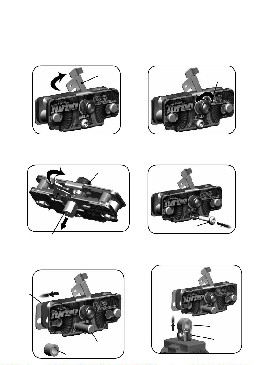
4.0 Montage des D-Ring-Verbindungselements an TurboLite-Geräte
WARNUNG: Die Montage des TurboLite-Geräts an das D-Ring-Verbindungselement muss von einer befugten
Person durchgeführt werden. Alle Miller-Höhensicherungsgeräte müssen vor jeder Nutzung inspiziert und
getestet werden (siehe 6.0 Inspektion und Wartung).
Die Arretierung des D-Ring-Stifts im Uhrzeigersinn bis
Schritt 1
zur vollständig geöneten Position drehen.
Arretierung des
D-Ring-Stifts
Den Knopf des D-Ring-Stifts gegen den Uhrzeigersinn
drehen, bis der D-Ring-Stift frei bewegt werden kann.
Schritt 2
Knopf des
D-Ring-Stifts
(a) Die D-Ring-Verbindung nach hinten neigen, damit der Stift des
D-Rings frei aus dem Schlitz des D-Rings gleiten kann.
(b) Die Arretierung des D-Ring-Stifts gegen den D-Ring-Stift
drehen, um ihn in Stellung zu halten.
B.
Arretierung
des D-Ring-
Stifts
Knopf des
D-Ring-Stifts
A.
D-Ring-Stift
Schritt 3
(a) Den äußeren Rahmen auf eine Seite schieben, wie hier abgebildet.
(b) Den PFL-Arretierstift und den PFL-Abstandhalter entfernen und
Äußerer
Rahmen
Schritt 5
beiseite legen.
A.
Den Gleitsicherungsbolzen mit Hilfe eines
Schritt 4
5/32” Inbusschlüssels entfernen und
beiseite legen.
Gleitsicherungsbolzen
Schritt 6
Den PFL-Abstandhalter in die Schlaufe des
TurboLite-Wirbels einsetzen und in den Schlitz
im D-Ring-Verbindungselement einführen.
B.
PFL-Arretierstift
PFL-Abstand-
halter
P F L - A b s tandhalter
TurboLite Wir-
belschlaufe
29
Page 30
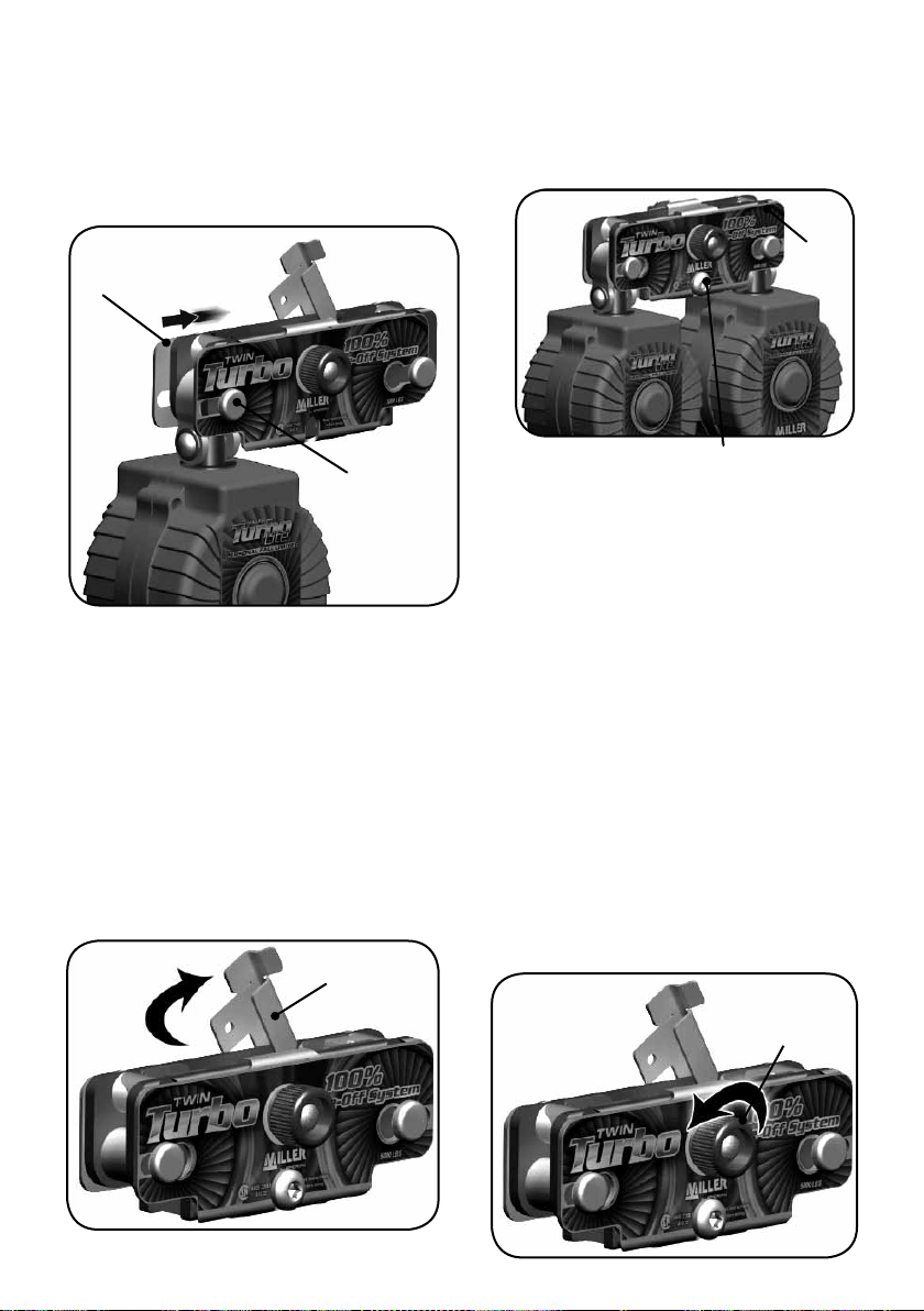
(a) PFL-Abstandhalter und TurboLite-Wirbelschlaufe
Schritt 7
ausrichten und den PFL-Arretierstift einschieben, bis der
Kopf den äußeren Rahmen berührt.
(b) Den äußeren Rahmen in mittige Position schieben, um
den PFL-Arretierstift einzurasten.
Um das andere TurboLite-Gerät anzubringen,
Schritt 8
wiederholen Sie die Schritte 5 – 7. Schieben Sie dabei
den äußeren Rahmen in die entgegengesetzte Richtung.
Äußerer
Rahmen
B.
PFL-Arretierstift
A.
Gleitsicherungsbolzen
Schritt 9
Nehmen Sie die Schritte 1 – 3 in umgekehrter
Reihenfolge vor, um den D-Ring-Stift und die
Arretierung des D-Ring-Stifts zu befestigen.
Äußerer
Rahmen
Schritt 10
Den Gleitsicherungsbolzen mit einem Inbusschlüssel
montieren und mit ca. 10 ft-lbs festziehen. (Umgekehrter
Schritt 4.)
5.0 Befestigung am hinteren D-Ring
WARNUNG: Dieses Gerät darf nur am hinteren D-Ring getragen werden. Es ist nicht kompatibel mit hinteren D-Ringen
mit Bandschlaufe.
Die Arretierung des D-Ring-Stifts im Uhrzeigersinn bis zur
Schritt 1
vollständig geöneten Position drehen.
Den Knopf des D-Ring-Stifts gegen den Uhrzeigersinn
drehen, bis der D-Ring-Stift frei bewegt werden kann.
Schritt 2
30
Arretierung des
D-Ring-Stifts
Knopf des
D-Ring-Stifts
Page 31

(a) Die D-Ring-Verbindung nach hinten neigen, damit der Stift
des D-Rings frei aus dem Schlitz des D-Rings gleiten kann.
(b) Die Arretierung des D-Ring-Stifts gegen den D-Ring-Stift
drehen, um ihn in Stellung zu halten.
B.
Arretierung des
D-Ring-Stifts
Knopf des
D-Ring-Stifts
A.
D-Ring-Stift
Schritt 3
Den hinteren D-Ring in den Schlitz einführen, bis
Schritt 4
er ganz einrastet und zur Unterseite des Schlitzes
hin sitzt.
Hinterer
D-Ring
Schlitz des
D-Ring-Stift
Den D-Ring-Stift durch die D-Ring-Önung schieben, bis er
das Gewinde des Knopfes des D-Ring-Stifts berührt
D-Ring-Stift
Den D-Ring-Stift gegen das Gewinde halten, dabei den
Knopf des D-Ring-Stifts im Uhrzeigersinn drehen und
Schritt 6
festziehen
Schritt 7
Schritt 5
Die Arretierung des D-Ring-Stiftes im Uhrzeigersinn drehen, bis er vollständig oben im D-Ring-Verbindungselement sitzt
A r r et i e rung des
D - R i n g Stifts
(die Rückseite des D-Ring-Stifts wird verdeckt).
WARNUNG:
Nur verwenden,
wenn die Arretierung des D-RingStifts vollständig
geschlossen ist.
GEHEN SIE DIE SCHRITTE 1 – 7 IN UMGEKEHRTER REIHENFOLGE DURCH,
UM DAS D-RING-VERBINDUNGSELEMENT VOM D-RING ZU ENTFERNEN.
31
Page 32

6.0 Inspektion und Wartung
6.1 Gebrauch und Inspektion
WARNUNG: GERÄTE, DIE EINE PRÜFUNG NICHT BESTEHEN ODER DIE DEN KRÄFTEN BEIM
AUFFANGEN EINES STURZES AUSGESETZT WAREN, MÜSSEN AUSSER BETRIEB GENOMMEN WERDEN.
6.1.0 Vor jeder Nutzung müssen die folgenden Punkte geprüft und die Inspektionen ausgeführt werden.
1. D-Ring-Stift:
a. Auf Risse und Spalten prüfen. Falls solche vorhanden sind, das
Gerät außer Betrieb nehmen.
b. Der D-Ring-Stift muss in etwa bündig sein mit der Rückseite des
inneren Rahmens.
2. Arretierung des D-Ring-Stifts:
In der geschlossenen Position muss die Arretierung weiterhin
das Ende des D-Ring-Stifts bedecken.
Auf Risse oder Spalten prüfen.
Bündiger
D-Ring-Stift
3a
3. Innerer Rahmen:
a. Die Bereiche über dem D-Ring-Stift müssen einwandfrei sein
(frei von Rissen, Spalten oder gedehntem Material).
b. Den Bereich um den PFL-Arretierstift inspizieren. Darf keine
Risse, Spalten oder gedehntes Material aufweisen.
c. Seitenplatten und Abstandhalter müssen gut befestigt sein,
ohne Spiel oder Bewegungsfreiheit zueinander.
4. Äußerer Rahmen:
Die Bereiche um den PFL-Arretierstift auf beiden Seiten des
äußeren Rahmens inspizieren. Außer Betrieb nehmen, wenn
eine Verdrehung festgestellt wird oder Materialien entfernt
wurden und innerhalb des inneren Rahmens kein PFL Arretierstift mehr vorhanden ist.
32
3b
4
Page 33

Arretierung
D-Ring-Stift
Äußerer Rahmen
D-Ring-Stift
PFL-Arretierstift
PFL-Abstandhalter
Gleitsicherungsbolzen
6.1.1 Nachstehende Inspektionen und Punkte für den Betrieb müssen jedes Jahr durchgeführt bzw. geprüft
werden.
HINWEIS: ALLE INSPEKTIONEN UNTER DEM PUNKT
„VOR JEDER NUTZUNG“ IN ABSCHNITT 6.1.0 MÜSSEN
ZUSÄTZLICH ZU DIESER VORGEHENSWEISE AUSGEFÜHRT
WERDEN.
1. Die Turbolite-Geräte gemäß den Anweisungen in Abschnitt 4 dieser Bedienungsanleitung vom D-Ring-Verbindungselement entfernen.
2. PFL-Arretierstift und Bereiche um die Löcher der Stiftarretierung
im inneren Rahmen auf Risse und Spalten prüfen.
3. Die inneren Mechanismen mit Pressluft oder mit einer weichen
Bürste reinigen und mögliche Verschmutzungen entfernen.
4. Die Turbolite-Geräte gemäß Abschnitt
33
Page 34

7.0 Wartung und aufbewahrung
Gute Wartung und richtige Aufbewahrung Ihrer PSA erhöhen die Lebensdauer des Produkts und
Halten Sie sich unbedingt an diese Empfehlungen:
• Reinigung: In mildem Seifenwasser reinigen. Niemals Lauge oder Lösungsmittel verwenden.
• Trocknen: An einem gut belüfteten Ort abseits von oenen Flammen oder anderen Hitzequellen trocknen lassen.
• Schmierung: Die beweglichen Teile mit einem Schmiermittel auf Silikonbasis einfetten. Die Schmierung erfolgt, na-
chdem das Produkt gereinigt und trocken ist.
• Desinfektion: Das Verbindungselement eine Stunde lang in eine Lösung aus lauwarmem Wasser mit Desinfektionsmittel auf Basis quaternärer Ammoniumsalze tauchen. Mit Trinkwasser spülen und mit einem sauberen Tuch
abwischen.
• Aufbewahrung: Bewahren Sie das nicht verpackte Produkt nach dem Reinigen, Trocknen und Schmieren an einem
trockenen, kühlen Ort ohne scharfe Kanten und ohne chemische oder korrosive Stoe auf.
Schützen Sie das Verbindungselement vor UV-Licht, vor direkten oder übermäßig starken Hitzequellen und vor zu ho-
her relativer Feuchtigkeit. Vermeiden Sie die Verwendung des Produkts in schmutziger Umgebung, und lagern Sie es
niemals ein, wenn es feucht ist.
7.1 Regelmässige inspektion
Diese Anweisungen müssen mit dem Artikel aufbewahrt werden. Bitte die Identizierungskarte verwenden, um die
Information vom Typenschild aufzuzeichnen. Die regelmäßige Inspektion dient der Überprüfung der Wirksamkeit und
Stärke der Ausrüstung; sie ist zur Gewährleistung der Nutzersicherheit unerlässlich. Die PSA muss mindestens ein Mal
pro Jahr vom Hersteller oder von einer befugten Person überprüft werden, und die Inspektion muss auf der Identizierungskarte erfasst werden. Die Inspektion muss häuger erfolgen, wenn Vorschriften dies erforderlich machen, wenn
die PSA oft benutzt wird oder wenn sie unter rauen Umgebungsbedingungen verwendet wird. Die Lesbarkeit der Produktkennzeichnung muss überprüft werden. (Abb. 6)
gewährleisten Ihre Sicherheit.
8.0 Produktetiketten
3
1
9
102xxxxx
6
Material: Aluminium/Edelstahl
34
BEDEUTUNG DER ETIKETTEN
1-Name, Markenname oder anderes Mittel,
anhand dessen sich der Hersteller oder der
Lieferant feststellen lässt
2-Artikelnummer
3-Artikelbezeichnung
4-Herstellungsdatum (Woche/Jahr)
5-Los- oder Seriennummer
2
7
8
4
5
6-Material(ien) der Bestandteile des
Ausrüstungsteils
7-EN xxx:xxxx: Nummer der Europäischen
Konformitätsnorm und Jahreszahl Klasse
T: abschließendes Verbindungselement
eines Untersystems, innerhalb dessen die
Belastung in eine vorgegebene Richtung
stattndet.
8-
0120 : EC-Logo, gefolgt von der
Nummer der Stelle, die zur Überprüfung
der Herstellung benannt wurde
9-
: Das Standard-Piktogramm, das den
Nutzer dazu auordert, die Unterlagen zu
lesen.
Page 35

E
MILLER TWIN TURBO
Conformes a la norma EN362: 2004
Instrucciones para El Usuario - Español
Gracias
Le agradecemos su compra de equipo anticaídas Miller. Los productos de la marca Miller son manufacturados para
cumplir con las más altas normas de calidad en nuestra fábrica, la cual posee la certicación ISO 9001:2000. Cuidados
como es debido, los equipos anticaídas Miller le servirán muchos años.
ADVERTENCIA
Toda persona que use este equipo debe leer, comprender y seguir cabalmente todas las instrucciones.
No hacerlo podría tener como consecuencia lesiones graves o mortales. No use este equipo si no ha sido
¿Consultas? LLAMAR AL 02.48.52.40.42
Es fundamental que la persona o usuario autorizado de este equipo anticaídas lea y comprenda las presentes instrucciones. Además, es responsabilidad del empleador que todos los usuarios hayan recibido capacitación para usar,
inspeccionar y dar el debido mantenimiento al equipo anticaídas. La capacitación anticaídas debe ser parte integral
de un programa completo de seguridad.
La utilización correcta de los sistemas de detención de caídas puede salvar vidas y disminuir las posibilidades de
lesiones graves en caso de una caída. Los usuarios deben estar conscientes de que las fuerzas ejercidas para detener
una caída o durante una suspensión prolongada pueden causar lesiones. Consulte a un médico en caso de duda
sobre la capacidad del usuario para emplear este producto. Las mujeres embarazadas y los niños no deben usar este
producto.
debidamente entrenado.
1.0 Propósito
Las cuerdas salvavidas autorretráctiles Miller, los limitadores de caídas y las cuerdas de seguridad tejidas retráctiles
son dispositivos completos retráctiles fabricados para ser usados en aplicaciones en las que el trabajador necesita
protección contra caídas y movilidad irrestricta.
2.0 Requisitos Generales
2.1 Advertencias Generales
Deben suministrarse a las personas y usuarios autorizados todas las advertencias e instrucciones.
Todas las personas y usuarios autorizados deben consultar los reglamentos de seguridad laboral y la norma CE que
correspondan.
Siempre deben tomarse las debidas precauciones al retirar del área de trabajo obstrucciones, basura, material y otros
peligros reconocidos que pudieran causar lesiones o interferir en el funcionamiento del sistema.
Todo el equipo debe ser inspeccionado visualmente antes de cada uso de conformidad con las instrucciones del fabri-
cante.
Todo el equipo debe ser inspeccionado con regularidad por una persona calicada.
A n de reducir al mínimo las posibilidades de un desenganche accidental, una persona competente debe garantizar
la compatibilidad del sistema.
El equipo no debe ser alterado de ninguna forma.
Las reparaciones deben ser efectuadas exclusivamente por el fabricante del equipo o bien por personas o entidades
autorizadas por escrito por el fabricante.
35
Page 36

Todo producto con deformidades, desgaste anormal o deterioro debe ser desechado de inmediato.
Todo equipo sometido a una caída debe ser puesto fuera de servicio.
El usuario debe contar con un plan y medios de rescate a mano para poder aplicarlos al usar este equipo.
Jamás lo utilice para nes distintos al proyectado. No use jamás el equipo para remolcar o izar objetos.
Debe protegerse todo el material sintético con el objeto de mantenerlo alejado de escorias, chispas calientes, llamas y
otras fuentes de calor. Para tales usos se recomienda el uso de materiales resistentes al calor.
Al seleccionar equipo anticaídas deben tomarse en cuenta los riesgos medioambientales. No debe exponerse el
equipo a sustancias químicas que puedan producir un efecto perjudicial. El uso del equipo en entornos muy corrosivos
o cáusticos exige un programa de inspecciones y servicio más frecuentes para garantizar la integridad continuada del
dispositivo. Si tiene dudas, comuníquese con el Depto. de Servicio Técnico de Miller.
No permita que la cuerda o el tejido entren en contacto con cualquier cosa que pueda dañarlos, como supercies
aladas, abrasivas, ásperas o a alta temperatura, soldadura, fuentes de calor, peligros eléctricos o maquinaria en movimiento.
Siempre revise para ver si hay obstrucciones abajo del área de trabajo con el n de asegurarse de que esté despejada
la trayectoria de una posible caída.
Evite los peligros de una caída columpiada; trabaje abajo del punto de anclaje.
Deje una distancia segura de caída adecuada abajo de la supercie de trabajo.
Nunca desprenda etiquetas de los productos, las cuales pueden incluir importantes advertencias e información para la
persona o usuario autorizado.
2.2 Advertencias y Limitaciones
Deben ser usados por UNA sola persona.
No use el dispositivo si no se retrae.
El aseguramiento del dispositivo debe probarse antes de cada uso.
Deben retirarse del servicio las cuerdas salvavidas si cualquier parte del sistema de las mismas parece dañado
o no pasa la inspección, o si la unidad ha sido sujeta a las fuerzas de detención de una caída.
No intente dar servicio a este dispositivo. Si una cuerda salvavidas autorretráctil no funciona debidamente o
necesita repararse, envíela para su reparación al fabricante del equipo o a un centro de servicio autorizado
por el fabricante. [Las unidades que no pasen la inspección y no puedan repararse deben ser desechadas de la
forma debida.]
No lubrique este dispositivo.
El dispositivo debe mantenerse limpio y libre de contaminantes.
Este dispositivo debe instalarse y usarse de tal manera que se reduzca al mínimo la posibilidad de una caída
columpiada.
Nunca trabaje arriba del dispositivo, a menos que que esté montado para usarse
dentro de una estructura (p. ej., elevadores, de conformidad con las instrucciones de instalación).
Nunca use el dispositivo como dispositivo restrictor o posicionador.
36
Page 37

3.0 Compatibilidad del Sistema
Las cuerdas salvavidas autorretráctiles Miller by Sperian están fabricadas para usarse con componentes aprobados
por dicha compañía. La sustitución o reemplazo de dichos componentes con combinaciones no aprobadas de
componentes o subsistemas, puede afectar o interferir en el funcionamiento seguro de cada componente y poner en
peligro la compatibilidad dentro del sistema. Esta incompatibilidad puede afectar la abilidad y seguridad del sistema
total.
3.1 Grupos de Productos Anticaídas Miller
Un programa integral anticaídas debe ser visto como un “sistema total” que comienza con el reconocimiento
del peligro y culmina con una revisión administrativa continua. Miller by Sperian considera sus productos como “un
sistema dentro de un sistema”. Tres componentes principales del “sistema Miller” deben estar en su lugar y usarse
debidamente para que puedan proporcionar la máxima protección al trabajador.
A. PUNTO DE ANCLAJE
Si fuera posible utilizar anclas estructurales (conforme a la EN 795), es
decir, elementos jados de manera duradera a una estructura (pared,
poste...).
De todos modos, siempre deberá vericar que el punto de anclaje:
• Tiene una resistencia mínima de 10 kN,
• Está situado encima del operador (ver 10).
• Se encuentra en el eje vertical de la supercie de trabajo: (ángulo
máximo ± 30°),
• Se adapte perfectamente al dispositivo de anclaje Del equipo.
• No presenta ningún ángulo cortante.
B. APAREJO
El segundo componente del sistema es el equipo de protección
personal que traen puesto los trabajadores mientras realizan su
labor. Miller by Sperian fabrica arneses de cuerpo entero, cinturones
de posicionamiento y cinturones para entornos de trabajo especícos.
Los arneses de cuerpo entero están diseñados para contribuir a la parada de una caída libre y se deben usar siempre que el trabajador esté
expuesto a una posible caída libre. Para reducir al mínimo las fuerzas
de la caída, el arnés de cuerpo entero se debe usar conjuntamente con
un equipo amortiguador de impacto. Es imperativo usar el arnés como
es debido.
C. DISPOSITIVO DE CONEXIÓN
El último componente del sistema es el dispositivo de conexión.
La característica más importante del dispositivo de conexión es el
amortiguador de impacto incorporado. Independientemente de que
dicho dispositivo sea una cuerda de seguridad con amortiguador de
impacto o una cuerda salvavidas retráctil, ambas están diseñadas para
reducir de manera impresionante las fuerzas ejercidas para detener la
caída
. Las cuerdas de seguridad de bra, tejidas o de alambre usadas para la
detención de caídas DEBEN usarse conjuntamente con un amortiguador de impacto.
De manera individual, ninguno de estos componentes ofrece protección contra una caída. Usados en conjunto
como es debido, conforman el “sistema Miller” y se convierten en una parte de vital importancia del “sistema
completo de protección contra caídas”.
A
B
C
3.2 Conectores (EN 362:2004):
Classe A: conector de anclaje: realizado para ser conectado directamente a un tipo especíco de anclaje
Classe B: conector base: ideado para ser utilizado como componente
Classe M: conector multiuso: se lo puede cargar ya sea en el eje mayor como en el eje menor
Classe T: conector terminal: elemento de un subsistema donde la carge actúa en una dirección preestalecida
Classe Q. conector con abrazadera a rosca: para ser utilizado en conexiones de larga duración o permanentes
El modelo de referencia está marcado sobre el dispositivo.
37
Page 38

4.0 Montaje del Conector para Argolla “D” a las Unidades TurboLite
ADVERTENCIA: Una persona autorizada debe realizar la instalación de las unidades TurboLite en el conec-
tor para argolla “D”. Todas las cuerdas salvavidas autorretráctiles deben inspeccionarse y probarse cada vez
Gire a la derecha el retén del pasador para argolla
“D” a la posición completamente abierta.
antes de usarse (ver el apartado 6.0, “Inspección y mantenimiento”).
Paso 1
Gire a la izquierda la perilla del pasador para
argolla “D” hasta que éste esté libre para moverlo.
Retén del
pasador para
argolla “D”
Paso 2
Perilla del
pasador para
argolla “D”
(a) Voltee hacia atrás el conector para argolla “D” para permitir
extraer el pasador de la ranura para dicha argolla.
(b) Gire el retén del pasador para argolla “D” con el n de ponerlo
contra el mismo para mantenerlo en su lugar.
Retén del
pasador para
argolla “D”
Pasador para argolla “D”
B.
A.
Perilla del pasador
para argolla “D”
Paso 5
(a) Deslice lateralmente la armazón exterior
como se muestra.
(b) Retire el pasador retenedor y el separador
para LCP y póngalos a un lado.
Paso 3
Armazón
exterior
A.
Paso 4
Retire el perno asegurador con una llave
hexagonal de 5/32” y póngalo a un lado.
Perno asegurador
Paso 6
Instale el separador para LCP en la argolla
oscilante de la unidad TurboLite y colóquelos
en la ranura del conector para argolla “D”.
38
B.
Separador para LCP
Pasador
retenedor
para LCP
Separador
para LCP
Argolla
oscilante de
TurboLite
Page 39

(a) Alinee el separador para el LCP y la argolla oscilante de
Paso 7
la unidad TurboLite y empuje el pasador retenedor para LCP
hasta que la cabeza toque la armazón exterior.
(b) Deslice al centro la armazón exterior para enganchar el
pasador retenedor para LCP.
Para instalar la otra unidad TurboLite repita los
Paso 8
pasos 5 a 7, deslizando la armazón exterior en la
dirección opuesta.
Armazón
exterior
B.
Pasador
retenedor para
LCP
A.
Slide Lock Bolt
Paso 9
Realice en sentido inverso los pasos 1 a
3 para asegurar el pasador para argolla
“D” y el retén del mismo.
Armazón
exterior
Paso 10
Instale el perno asegurador con una llave
hexagonal , apretándolo a 13.6
N•m (10 lb•pie).
5.0 Fijación en la Argolla “D” Posterior
ADVERTENCIA: Este dispositivo sólo debe colocarse en la argolla “D” posterior y no es
compatible con argollas “D” posteriores de lazos tejidos.
Paso 1
Gire a la derecha el retén del pasador para argolla
“D” a la posición completamente abierta.
Gire a la izquierda la perilla del pasador para
argolla “D” hasta que éste esté libre para moverlo.
Paso 2
Retén del
pasador para
argolla “D”
Perilla del
pasador para
argolla “D”
39
Page 40

(a) Voltee hacia atrás el conector para argolla “D” para permitir
extraer el pasador de la ranura para dicha argolla.
(b) Gire el retén del pasador para argolla “D” con el n de ponerlo
contra el mismo para mantenerlo en su lugar.
Retén del
pasador para
argolla “D”
Pasador para argolla “D”
Perilla del pasador
para argolla “D”
B.
A.
Paso 5
Empuje el pasador para argolla “D” a través de
la abertura para ésta hasta que toque la rosca
de la perilla del pasador para dicha argolla.
Pasador para
argolla “D”
Paso 3
Introduzca la argolla “D” posterior en la ranura
Paso 4
hasta dejarla completamente enganchada y
asentada contra la parte inferior de la ranura.
Argolla “D”
posterior
Ranura para
argolla “D”
Paso 6
Mientras mantiene el pasador para argolla
“D” contra la rosca, gire a la derecha la perilla
del mismo y apriételo.
Gire a la derecha el retén del pasador para argolla “D” hasta dejar éste completamente asentado
Paso 7
contra la parte superior del conector para dicha argolla (debe cubrir la parte posterior del pasador).
Retén del
pasador
para
argolla “D”
PARA RETIRAR DE LA ARGOLLA “D” EL CONECTOR, REALICE EN SENTIDO I
NVERSO LOS PASOS 1 A 7.
40
ADVERTENCIA:
No use la unidad
si el retén del
pasador para
argolla “D” no
está completamente cerrado.
Page 41

6.0 Inspección y Mantenimiento
6.1 Funcionamiento e inspección
ADVERTENCIA: LAS UNIDADES QUE NO PASEN LA INSPECCIÓN O HAYAN SIDO
SOMETIDAS A FUERZAS DE DETENCIÓN DE CAÍDAS DEBEN RETIRARSE DEL SERVICIO.
7.1.0 Cada vez antes de usar el equipo deben efectuarse las
siguientes revisiones e inspecciones.
1. Pasador para argolla “D”:
a. Inspeccionar para ver si hay agrietamientos o rajaduras. Si dichos daños están presentes la unidad debe retirarse del servicio.
b. El pasador debe estar aproximadamente a ras con la parte
posterior de la armazón interior.
Pasador para
argolla “D”
a ras
2. Retén del pasador para argolla “D”:
Cuando está en la posición cerrada el retén debe permanecer
cubriendo el extremo del pasador. Inspeccionar para ver si hay
agrietamientos o rajaduras.
3. Armazón interior:
a. Las áreas arriba del pasador para argolla “D” deben estar libres de
agrietamientos, rajaduras o material estirado.
b. Inspeccionar el área alrededor de los pasadores retenedores para
los LCP. Deben estar libres de agrietamientos, rajaduras o material
estirado.
c. Las placas laterales y separadores deben estar seguros y sin nada
de juego ni movimiento relativo entre ellos.
4. Armazón exterior:
Inspeccionar las áreas alrededor de los pasadores retenedores para
LCP, a ambos lados de la armazón exterior. La unidad debe
retirarse del servicio si hay distorsión o hay material faltante y ya no
contiene dentro de la armazón interior los pasadores retenedores
para LCP.
3a
3b
4
41
Page 42

Retén del
pasador para
argolla “D”
Pasador para
argolla “D”
6.1.1 Las siguientes revisiones e inspecciones deben efectuarse una vez al año.
NOTA: ADEMÁS DE ESTE PROCEDIMIENTO DEBEN REALIZARSE TODAS LAS INSPECCIONES PARA “ANTES DE
CADA USO” SEÑALADAS EN LA SECCIÓN 6.1.0.
1. Retirar las unidades Turbolite del conector para argolla “D” de conformidad con las instrucciones señaladas en la
sección 4 de este manual.
2. Inspeccionar los pasadores retenedores para LCP y las áreas alrededor de los agujeros de la armazón interior
correspondientes al retén del pasador para ver si tienen agrietamientos o rajaduras.
3. Limpiar los mecanismos interiores con aire comprimido o con cepillo de cerda para eliminar toda la basura presente.
4. Instalar de nuevo las unidades Turbolite en el conector para argolla “D” de conformidad con las instrucciones
señaladas en la sección 5 de este manual.
Armazón exterior
Pasador retenedor
para LCP
Separador para
LCP
Perno
asegurador
42
Page 43

7.0 Mantenimiento y almacenamiento
Un buen mantenimiento así como un almacenamiento adecuado de su Epi garantizarán al producto una mayor
longevidad, garantizando al mismo tiempo su seguridad.
Vele por respetar estrictamente estas recomendaciones:
• Limpieza: límpielo con agua y jabón suave. No utilice nunca disolventes ácidos o bases.
• Secado: póngalo a secar en un lugar ventilado y alejado de los fuegos directos o de cualquier otra fuente de calor.
• Lubricación: lubrique las partes móviles con un lubricante a base de silicona. La lubricación se efectúa después de la
limpieza y el secado del producto.
• Desinfección: sumerja el conector durante una hora en una solución de agua templada y de un desinfectante a base
de sales de amonio cuaternarias. Adárelo con agua potable y límpielo con un paño limpio.
• Almacenamiento: después de la limpieza, secado y lubricación, guarde el producto desembalado en un lugar seco y
fresco, alejado de cualquier objeto agudo y producto químico o corrosivo.
Conserve el conector en un lugar protegido contra los rayos UV, las fuentes directas o excesivas de calor y un indice
demasiado elevado de humedad. Evite utilizar el producto en un entorno salado y no lo guarde mojado.
7.1 examen peri ódico
Estas instrucciones deberán conservarse con el producto. Rellene la cha de identicación anotando las informaciones
del marcado. Este examen periódico que verica la ecacia y la resistencia del equipo es indispensable para garantizar
la seguridad del usuario. Este EPI deber ser examinado al menos una vez al año por el fabricante o una persona autorizada; la vericación deberá ser registrada en la cha de identicación.
La frecuencia de examen debe estar aumentada en función de la reglamentación, en el caso de una utilización importante o en condiciones medioambientales difíciles.
Deberá vericarse la legibilidad de los marcados del producto.
8.0 Etiquetas del Producto
SIGNIFICACIÓN DEL MARCADO
3
1- El nombre, la marca comercial o cualquier
otra marca de identicación del fabricante
1
2
9
102xxxxx
6
Material: Aluminio/Acero inoxydable
7
8
4
5
o del proveedor
2- La referencia del producto
3- La designación del producto
4- La fecha de fabricación (semana /año)
5- El número de lote o el número de serie
6- El o los materiales de las componentes del
equipo
7- EN xxx: xxxx: Número de las normas
europeas de conformidad y su año Classe
T: conector terminal: elemento de un
subsistema donde la carge actùa en el eje
menor
8-
0120: Logotipo de la CE seguido desde
n° del organismo noticado que interviene
en la fase de control de la producción
9-
: El pictograma normalizado que indica
al usuario leer la noticia
43
Page 44

P
MILLER TWIN TURBO
EN362: 2004
Instruções para o utilizador – Português
Obrigado
Obrigado por ter adquirido um equipamento de protecção contra quedas Miller. Os produtos da marca Miller são produzidos para cumprir as mais elevadas normas de qualidade na nossa fábrica, que possui a certicação ISO 9001:2000.
Se for devidamente utilizado, o equipamento de protecção contra quedas Miller irá proporcionar-lhe muitos anos de
serviço.
ADVERTÊNCIA
Todas as pessoas que utilizem este equipamento têm de ler, compreender e respeitar todas as instruções. A não
observância das instruções poderá resultar em lesões graves ou mortais. Não utilize este equipamento se não tiver
recebido formação adequada.
Dúvidas? LIGUE PARA: +33.(0)2.48.52.40.42
É fundamental que a pessoa ou o utilizador autorizado deste equipamento de protecção contra quedas leia e compreenda estas instruções. Além disso, é da responsabilidade da entidade patronal garantir que todos os utilizadores
recebem formação sobre a utilização, inspecção e manutenção correctas de equipamento de protecção contra quedas.
A formação de protecção contra quedas deve ser parte integrante de um programa exaustivo de segurança.
A utilização adequada de sistemas anti-queda pode salvar vidas e reduzir o potencial de lesões graves decorrentes de
uma queda. O utilizador deve estar ciente de que as forças exercidas para interromper uma queda ou resultantes de
suspensão prolongada podem causar lesões físicas. Consulte um médico caso tenha quaisquer dúvidas acerca da capacidade do utilizador para utilizar este produto. Mulheres grávidas e menores não devem utilizar este produto.
1.0 Finalidade
As cordas de segurança auto-retrácteis Miller, incluindo os limitadores de queda e as cintas retrácteis em têxtil, são
dispositivos retrácteis autónomos concebidos para ser utilizados por pessoal em aplicações nas quais é necessária uma
combinação de protecção contra quedas e de mobilidade total do trabalhador.
2.0 Requisitos gerais
2.1 Advertências g erais
Todas as advertências e instruções devem ser fornecidas às pessoas/utilizadores autorizados.
Todas as pessoas/utilizadores autorizados devem consultar os regulamentos aplicáveis em matéria de segurança labo-
ral, bem como as normas ANSI ou CSA aplicáveis.
Deve ter-se sempre o especial cuidado de retirar quaisquer obstáculos, resíduos, materiais ou outros perigos reconhe-
cidos da área de trabalho que sejam susceptíveis de causar lesões ou de interferir com o funcionamento do sistema.
Todo o equipamento deve ser inspeccionado antes de cada utilização de acordo com as instruções do fabricante.
Todo o equipamento deve ser regularmente inspeccionado por uma pessoa devidamente qualicada.
De modo a minimizar o risco de desengate acidental, uma pessoa competente deve garantir a compatibilidade do
sistema.
O equipamento não deve ser alterado de qualquer forma que seja. As reparações devem ser apenas realizadas pelo
fabricante ou por pessoas ou entidades autorizadas por escrito pelo fabricante.
Qualquer produto que apresente deformações, desgaste anormal ou deterioração deve ser imediatamente eliminado.
44
Page 45

Qualquer equipamento que tenha sido sujeito a uma queda deve ser retirado de utilização.
A pessoa/utilizador autorizado deve ter um plano de salvamento e dispor dos meios necessários para o implementar
ao utilizar este equipamento.
Nunca utilize equipamento de protecção contra quedas para outros ns diferentes daqueles para os quais foi conce-
bido. Nunca deve utilizar-se equipamento de protecção contra quedas para rebocar ou içar objectos.
Todo o material sintético deve ser protegido de escórias, faíscas, chamas vivas ou outras fontes de calor. Recomenda-se
a utilização de materiais resistentes ao calor nestas aplicações.
Devem considerar-se os perigos ambientais ao escolher equipamento de protecção contra quedas. O equipamento
não deve ser exposto a produtos químicos que possam ter um efeito nocivo. Deve utilizar-se poliéster em determinados ambientes químicos ou ácidos. A utilização em ambientes altamente corrosivos ou cáusticos implica um programa
mais frequente de inspecção e manutenção, de modo a garantir a integridade do dispositivo. Entre em contacto com
os serviços de assistência técnica da Miller caso tenha quaisquer dúvidas.
Não permita que o equipamento entre em contacto com quaisquer objectos que possam danicá-lo, incluindo (mas
não em exclusivo) arestas aguçadas ou superfícies abrasivas, ásperas ou a alta temperatura, soldaduras, fontes de calor,
perigos eléctricos ou máquinas em movimento.
Certique-se sempre de que não existem obstáculos por baixo da área de trabalho para garantir uma trajectória de
queda potencial desimpedida.
Preveja sempre uma distância segura de queda adequada por baixo da superfície de trabalho.
Nunca retire etiquetas dos produtos que comportem advertências e informações importantes para a pessoa/utilizador
autorizado.
2.2 Advertências e limitações
Para ser utilizado por UMA única pessoa.
Não utilize o dispositivo se este não se retrair.
A devida xação do dispositivo deve ser testada antes de cada utilização.
As cordas de segurança auto-retrácteis devem ser retiradas de utilização se qualquer parte do sistema
apresentar danos ou reprovar na inspecção, ou se a unidade tiver sido sujeita a forças de interrupção de uma
queda.
Não tente realizar qualquer reparação neste dispositivo. Se uma corda de segurança auto-retráctil não funcionar correctamente ou precisar de ser reparada, devolva o dispositivo ao fabricante do equipamento ou ao
serviço de reparação autorizado por escrito pelo fabricante. [As unidades que reprovarem na inspecção e que
não possam ser reparadas devem ser devidamente eliminadas.]
Não lubrique este dispositivo.
O dispositivo tem de ser mantido limpo e livre de quaisquer contaminantes.
O dispositivo deve ser instalado e utilizado de uma forma que minimize o risco de uma queda por balanço.
Nunca trabalhe acima do dispositivo, excepto se estiver montado para utilização numa estrutura (por exem-
plo, elevadores, de acordo com as instruções de instalação).
Nunca utilize o dispositivo como dispositivo de restrição ou de posicionamento.
45
Page 46

3.0 Compatibilidade do sistema
As cordas de segurança auto-retrácteis Miller foram concebidas para ser utilizadas com componentes aprovados Miller
by Sperian. A substituição ou troca por combinações não aprovadas de componentes, subsistemas ou ambos pode
afectar ou interferir com o funcionamento seguro de cada elemento e comprometer a compatibilidade dentro do sistema. Esta incompatibilidade pode afectar a abilidade e a segurança do sistema total.
3.1 Grupos de produtos de protecção contra quedas Miller
Um programa exaustivo de protecção contra quedas deve ser visto como um “sistema total”, começando pela identicação dos perigos e terminando com uma revisão administrativa contínua. A Miller by Sperian considera os seus
produtos como “um sistema dentro de um sistema”. Três componentes principais do “sistema Miller” têm de estar implementados e ser correctamente utilizados para fornecer a máxima protecção ao trabalhador.
A. PONTO DE ANCORAGEM
Se possível, utilize âncoras estruturais (em conformidade com a norma EN
795), ou seja, elementos xos de forma duradoura a uma estrutura (parede,
poste, etc.)
Em todos os casos, verique que o ponto de ancoragem:
• apresenta uma resistência superior a 10 kN;
• está situado acima do operador;
• se encontra num eixo vertical em relação à superfície de trabalho: (ângulo
máximo ± 30°);
• se adapta perfeitamente ao dispositivo de ancoragem do equipamento.
• não possui quaisquer arestas aguçadas.
B. EQUIPAMENTO DE PROTECÇÃO INDIVIDUAL
O segundo componente do sistema é o equipamento de protecção individual
utilizado pelos trabalhadores enquanto realizam o seu trabalho. A Miller by
Sperian fabrica arneses de corpo inteiro, cintos de posicionamento e cintos
para utilização em ambientes de trabalho especícos. Os arneses de corpo inteiro destinam-se a auxiliar na interrupção de uma queda livre e devem ser utilizados em todas as situações em que os trabalhadores estejam sujeitos a uma
potencial queda livre. O arnês de corpo inteiro deve ser utilizado em conjunto
com equipamento de amortecimento de choques de modo a manter as forças de queda a um nível mínimo. É imperativo que o arnês seja devidamente
utilizado.
C. DISPOSITIVO DE CONEXÃO
O terceiro componente do sistema é o dispositivo de conexão. A característica mais importante do dispositivo de
conexão é o amortecedor de choques integrado. Independentemente de o dispositivo de conexão ser uma corda de
amortecimento de choques ou uma corda de segurança auto-retráctil, ambas foram concebidas para reduzir consideravelmente todas as forças de interrupção de uma queda. As cordas de segurança de bra, têxtil ou cabo utilizadas para
a interrupção de uma queda TÊM de ser utilizadas em conjunto com um amortecedor de choques.
Isoladamente, nenhum destes componentes irá fornecer protecção contra uma queda. Utilizados devidamente
e em conjunto, formam o “sistema Miller” e tornam-se uma parte crucialmente importante do “sistema total de
protecção contra quedas”.
A
B
C
3.2 TIPOS DE CONECTORES (EN 362:2004)
Classe A: conector de ancoragem – componente concebido para ser ligado directamente a um tipo especíco de
ancoragem.
Classe B: conector básico – concebido para ser utilizado como um componente.
Classe M: conector multiusos – componente que pode ser carregado tanto no eixo maior como no eixo menor.
Classe T: conector terminal – elemento de um subsistema no qual a carga é exercida num sentido pré-determinado.
Classe Q: conector com mosquetão de rosca – concebido para ser utilizado apenas para ligações duradouras ou
permanentes.A identicação da classe está marcada no dispositivo.
46
Page 47

4.0 Montagem do conector da argola em D nas unidades TurboLite
ADVERTÊNCIA: uma pessoa autorizada deve realizar a instalação de unidades TurboLite no conector
da argola em D. Todas as cordas de segurança auto-retrácteis Miller devem ser inspeccionadas e
testadas antes de cada utilização (consulte a Secção 6.0, “Inspecção e manutenção”).
Rode o retentor do perno da argola em D para a
direita até à posição totalmente aberta
Retentor do
perno da argola
em D
Rode o botão do perno da argola em D para a esquerda
Passo 3
Passo 1
(a) Incline o conector da argola em D para trás de modo a permitir que
o perno da argola em D deslize para fora da ranhura da argola.
(b) Rode o retentor do perno da argola em D contra o perno de modo
Retentor do
perno da
argola em D
a mantê-lo no lugar.
B.
Botão do perno
da argola em D
A.
Perno da argola em D
(a) Faça deslizar a armação exterior para um lado, como ilustrado.
(b) Retire o perno de retenção PFL e o espaçador PFL e coloque-os
Passo 5
de lado.
Passo 2
até que o perno que livre para ser movido.
Botão do perno
da argola em D
Passo 4
Retire o parafuso deslizante de xação com
uma chave sextavada de 5/32» e coloque-o
Parafuso deslizante de xação
de lado.
Passo 6
Instale o espaçador PFL na alça articulada
TurboLite e coloque na ranhura no conector da
argola em D.
Armação
exterior
A.
Espaçador PFL
B.
Perno de retenção PFL
Espaçador
PFL
Alça articulada
TurboLite
47
Page 48

(a) Alinhe o espaçador PFL e a alça articulada TurboLite e
Passo 7
empurre o perno de retenção PFL até que a cabeça entre em
contacto com a armação exterior.
(b) Faça deslizar a armação exterior para a posição central
para reter o perno de retenção PFL.
Para instalar a outra unidade TurboLite, repita os passos
Passo 8
5 a 7, deslizando a armação exterior no sentido oposto.
Armação
exterior
B.
Perno de retenção
PFL
A.
Parafuso deslizante de xação
Passo 9
Repita os passos 1 a 3 pela ordem inversa para xar o perno
da argola em D e o retentor do perno da argola em D.
Armação
exterior
Passo 10
Instale o parafuso deslizante de xação com uma chave
sextavada e aperte-o com um binário de cerca de 13,6 Nm
10 pés-pol.) (Passo 4 pela ordem inversa).
5.0 Fixação na argola em D dorsal
ADVERTÊNCIA : este dispositivo deve apenas ser utilizado na argola em D dorsal e não
é compatível com argolas em D dorsais com laços em têxtil.
Rode o retentor do perno da argola em D para a direita até
Passo 1
à posição totalmente aberta.
Rode o botão do perno da argola em D para a esquerda
até que o perno que livre para ser movido.
Passo 2
48
Retentor do
perno da argola
em D
Botão do perno
da argola em D
Page 49

Passo 3
(a) Incline o conector da argola em D para trás de modo a permitir
que o perno da argola em D deslize para fora da ranhura da argola.
(b) Rode o retentor do perno da argola em D contra o perno de modo
a mantê-lo no lugar.
Botão do
perno da
argola em D
Retentor do
perno da argola
em D
B.
A.
Perno da argola em D
Empurre o perno da argola em D através da abertura da
argola em D até que entre em contacto com as roscas do
Perno da
argola em D
botão do perno da argola em D.
Passo 5
roscas, rode o botão do perno da argola em D para a direita
Introduza a argola em D dorsal na ranhura até que
que completamente encaixada e apoiada no
fundo da ranhura.
Ranhura do
argola em D
Argola
em D
dorsal
perno da
Passo 6
Enquanto mantém o perno da argola em D contra as
e aperte-o.
Passo 4
Rode o retentor do perno da argola em D para a direita até que que totalmente apoiado contra a parte superior do
Retentor
do perno
da argola
em D
conector da argola em D (deve cobrir a parte traseira do perno da argola em D).
ADVERTÊNCIA:
Não utilize a
não ser que o
retentor do pernoda argola em D
estiver completa-
mente fechado
PARA RETIRAR O CONECTOR DA ARGOLA EM D, REPITA OS
PASSOS 1 A 7 PELA ORDEM INVERSA.
Passo 7
49
Page 50

6.0 Inspecção e manutenção
6.1 Funcionamento e inspecção
ADVERTÊNCIA: AS UNIDADES QUE REPROVEM NA INSPECÇÃO OU TENHAM SIDO SUJEITAS A FORÇAS
DE INTERRUPÇÃO DE UMA QUEDA DEVEM SER RETIRADAS DE SERVIÇO.
6.1.0 As seguintes vericações de funcionamento e inspecções devem ser realizadas antes de cada utilização.
1. Perno da argola em D:
a. Inspeccione em relação a fendas ou ssuras. Caso existam, retire
de serviço.
b. O perno da argola em D deve estar aproximadamente ao mesmo nível da parte traseira da armação interior.
2. Retentor do perno da argola em D:
O retentor deve cobrir a extremidade do perno da argola em
D quando o mesmo está na posição fechada. Inspeccione em
relação a fendas ou ssuras.
Nivelado Perno
da argola em D
3a
3. Armação interior:
a. As áreas por cima do perno da argola em D devem estar
livres de fendas, ssuras ou material esticado.
b. Inspeccione a área em torno dos pernos de retenção PFL.
Tem de estar livre de fendas, ssuras ou material esticado.
c. As chapas laterais e os espaçadores devem estar bem xos,
sem qualquer folga ou movimento relativo entre os mesmos.
4. Armação exterior:
Inspeccione as áreas em torno dos pernos de retenção PFL de
ambos os lados da armação exterior. Retire de serviço em caso
de distorção ou de falta de material e se já não contiver pernos
de retenção PFL dentro da armação interior.
50
3b
4
Page 51

Retentor do
perno da argola
em D
Perno da
argola em D
Armação
exterior
Perno de reten-
ção PFL
Espaçador PFL
Parafuso deslizante de
xação
6.1.1 As seguintes vericações de funcionamento e inspecções devem ser realizadas
todos os anos.
OBSERVAÇÃO: TODAS AS INSPECÇÕES “ANTES DE CADA UTILIZAÇÃO” INDICADAS NA SECÇÃO 6.1.0
1. Retire as unidades Turbolite do conector da argola em D de acordo com as instruções na Secção 4 deste manual.
2. Inspeccione os pernos de retenção PFL e as áreas em torno dos orifícios dos pernos de retenção na armação interior
em relação a fendas ou ssuras.
3. Limpe os mecanismos internos com ar comprimido ou com uma escova de cerdas para eliminar quaisquer resíduos.
4. Volte a instalar as unidades Turbolite no conector da argola em D de acordo com as instruções na Secção 5 deste
manual.
TÊM DE SER REALIZADAS PARA ALÉM DESTE PROCEDIMENTO.
51
Page 52

7.0 Manutenção e armazenamento
Uma boa manutenção e um armazenamento adequado do seu EPI prolongam a vida útil do seu produto, ao mesmo
tempo que garantem a sua segurança.
Certique-se de que cumpre as seguintes recomendações:
• Limpeza: limpe-o com água e um detergente suave. Nunca adicione solventes ácidos ou alcalinos.
• Secagem: deixe-o secar num local devidamente arejado, afastado de qualquer chama directa ou de qualquer outra
fonte de calor.
• Lubricação: lubrique as peças móveis com um lubricante à base de silicone. A lubricação é realizada após a
limpeza e a secagem do produto.
• Desinfecção: imirja o conector durante uma hora numa solução de água morna e desinfectante à base de sais de
bases amoniacais quaternárias. Passe por água potável e enxugue com um pano limpo.
• Armazenamento: após a limpeza, secagem e lubricação, armazene o produto fora da embalagem num local seco
e fresco, afastado de quaisquer arestas aguçadas e de produtos químicos ou corrosivos. Mantenha o conector ao
abrigo dos raios UV, fontes directas ou excessivas de calor e demasiada humidade relativa. Evite utilizar o produto
num ambiente sujo e nunca o guarde ainda molhado.
7.1 Inspecção periódica
Estas instruções devem ser conservadas com o produto. Utilize o cartão de identicação para registar as informações
da etiqueta. A inspecção periódica deve vericar a ecácia e a resistência do equipamento e é essencial para garantir
a segurança do utilizador.
O EPI deve ser inspeccionado pelo menos uma vez por ano pelo fabricante ou por uma pessoa autorizada e a inspecção
deve ser registada no cartão de identicação. A frequência de inspecção deve ser aumentada de acordo com os regulamentos, em caso de utilização frequente ou de utilização em condições ambientais adversas. A legibilidade da etiqueta
do produto deve ser vericada. (imagem n.º 6)
8.0 Etiquetas do produto
3
1
2
9
102xxxxx
6
Material: alumínio/aço inoxidável
52
SIGNIFICADO DAS MARCAÇÕES
1 - O nome, a marca ou quaisquer outras
formas de identicação do fabricante ou do
fornecedor
2 - A referência do produto
3 - A designação do produto
4 - A data de fabrico (semana/ano)
5 - O número de lote ou de série
7
8
4
5
6 - O(s) material(ais) dos componentes do
equipamento
7 - EN xxx:xxxx: número das normas europeias
de conformidade e respectivo ano Classe T:
conectores terminais: elemento de um subsistema no qual a carga é exercida num sentido
pré-determinado
8-
0120 : logótipo CE seguido do
número do organismo noticado que
intervém na monitorização da produçãoe
9-
: o pictograma normalizado que
indica ao utilizador que deve ler as
instruções
Page 53

NL
MILLER TWIN TURBO
EN362: 2004
Gebruiksaanwijzing – Nederlands
Dank u
Dank u voor uw aankoop van een valbeveiligingsuitrusting van Miller. De producten van het merk Miller worden geproduceerd volgens de hoogste kwaliteitsnormen in onze ISO 9001:2000-gecerticeerde fabriek. De valbeveiligingsuitrusting van Miller zal jarenlang meegaan, onder voorwaarde dat er correct mee omgegaan wordt.
WAARSCHUWING
Alle personen die deze uitrusting gebruiken moeten de gebruiksaanwijzing gelezen, begrepen hebben en deze
opvolgen. Indien dit niet gebeurt, kan dit resulteren in ernstige verwondingen of zelfs de dood. Gebruik deze
uitrusting niet indien u niet correct opgeleid bent.
Vragen? BEL +33 (0)2.48.52.40.42
De geautoriseerde persoon/gebruiker van deze beveiliging moet deze gebruiksaanwijzingen zorgvuldig gelezen hebben en begrijpen. Bovendien is het de verantwoordelijkheid van de werkgever ervoor te zorgen dat alle gebruikers
opgeleid zijn met het oog op een correct gebruik, de inspectie en het onderhoud van de uitrusting. Deze opleiding
moet wezenlijk deel uitmaken van een omvattend veiligheidsprogramma.
Een correct gebruik van de beveiligingen kan levens redden en het risico van ernstige verwondingen ten gevolge van
een val beperken. De gebruiker moet zich er bewust van zijn dat krachten toegepast tijdens de stop van een val of een
langdurige ophanging lichamelijk letsel kan veroorzaken. Raadpleeg een arts indien u vragen hebt over het vermogen
van de gebruiker voor het gebruiken van dit product. Zwangere vrouwen en minderjarigen mogen dit product niet
gebruiken.
1.0 Doel
De zelntrekkende reddingslijnen van Miller, inclusief Valbegrenzers en Intrekbare Verbindingslijnen zijn autonome
intrekbare inrichtingen ontworpen voor gebruik door personeel bij toepassingen waarbij een valbeveiliging in combinatie met een onbeperkte mobiliteit van de arbeider vereist is.
2.0 Algemene Vereisten
2.1 Algemene Waarschuwingen
Alle waarschuwingen en instructies worden alleen aan geautoriseerd personeel/gebruikers verschaft.
Alle geautoriseerde personen/gebruikers moeten de veiligheidsvoorschriften en van toepassing zijnde ANSI- of CSA-
normen navolgen.
Men moet altijd de nodige voorzorgsmaatregelen treen voor de verwijdering van hindernissen, afval, materiaal of
andere erkende gevaren aanwezig in de werkzone of die aanleiding kunnen geven tot verwondingen of de werking
van het systeem in het gedrang kunnen brengen.
Alle uitrustingen moeten geïnspecteerd worden voor gebruik, volgens de instructies van de fabrikant.
Alle uitrustingen moeten regelmatig gecontroleerd worden door een gekwaliceerd persoon.
Om het gevaar van accidentele uitschakelingen te beperken, moet een competent persoon instaan voor de systeem-
compatibiliteit.
De uitrusting mag niet gewijzigd worden. Reparaties mogen uitsluitend door de fabrikant uitgevoerd worden of perso-
nen/entiteiten die schriftelijk geautoriseerd zijn door de fabrikant.
53
Page 54

Producten die afwijkingen vertonen, ongebruikelijke slijtage of schade, moeten onmiddellijk buiten gebruik gesteld
worden.
Elke uitrusting die gevallen is mag niet langer gebruikt worden.
De geautoriseerde persoon/gebruiker moet een reddingsplan en de nodige middelen bij de hand hebben wanneer
gebruik gemaakt wordt van deze uitrusting.
Gebruik de uitrusting nooit voor doeleinden verschillend van die waarvoor de uitrusting ontworpen is. De uitrusting
mag nooit gebruikt worden om te slepen of te hijsen.
Elk synthetisch materiaal moet beschermd worden tegen warmtebronnen en open vuur. Het gebruik van hittebesten-
dig materiaal is aanbevolen voor deze toepassingen.
Het milieu moet in aanmerking genomen worden bij de keuze van een uitrusting voor valbeveiliging. De uitrusting
mag niet blootgesteld worden aan chemische producten die schadelijke eecten kunnen hebben. Polyester moet gebruikt worden in bepaalde chemische of zure omgevingen. Een gebruik in een bijzonder corrosieve of bijtende omgeving houdt in dat frequentere inspectie- en onderhoudsbeurten voorzien moeten worden om de integriteit van de
uitrusting in stand te houden. Contacteer de technische service van Miller in geval van twijfel.
De uitrusting mag niet in contact komen met al wat schade kan aanrichten zoals scherpe, schurende, ruwe of hete
oppervlakken, lashandelingen, warmtebronnen, elektrische risico’s gevaar of bewegende machines.
Ga altijd de aanwezigheid na van hindernissen onder de werkzone, om er zeker van te zijn dat de potentiële valruimte
vrij is.
Voorzie voldoende valhoogte onder het werkoppervlakte.
Verwijder nooit de productlabels, die belangrijke waarschuwingen en informatie bevatten voor de geautoriseerde per-
soon/gebruiker.
2.2 Waarschuwingen en Beperkingen
Voor gebruik door slechts EEN persoon.
Gebruik de inrichting niet indien het band niet oprolt.
De vergrendeling van de inrichting moet getest worden voor elk gebruik.
Zelntrekkende reddingslijnen mogen niet gebruikt worden indien een onderdeel van het systeem bescha-
digd lijkt of de inspectie niet doormaakt, of indien de eenheid onderhevig geweest is aan de kracht van een
valstop.
Probeer deze uitrusting niet zelf te onderhouden. Indien een zelntrekkende reddingslijn niet correct werkt of
gerepareerd moet worden, moet hij teruggestuurd worden naar de fabrikant of een door de fabrikant schriftelijk geautoriseerd servicecentrum. [De eenheden die geen inspectie krijgen en niet gerepareerd worden,
moeten op correcte wijze buiten gebruik gesteld worden.]
Smeer deze inrichting niet.
De inrichting moet schoon en vrij van vervuilende deeltjes gehouden worden.
De inrichting moet geïnstalleerd en gebruikt worden op een dusdanige manier dat het gevaar van een slinge-
rende val geminimaliseerd wordt.
Werk nooit boven de inrichting, tenzij die gemonteerd wordt voor gebruik binnen een structuur (vb. liften, in
overeenstemming met de aanwijzingen voor de installatie).
Gebruik de inrichting nooit om tegen te houden of te positioneren.
54
Page 55

3.0 Systeemcompatibiliteit
De intrekkende reddingslijnen van Miller zijn ontworpen om gebruikt te worden met componenten goedgekeurd door
Miller by Sperian. De vervanging door combinaties en/of subsystemen die niet geautoriseerd zijn kan een negatieve
invloed hebben op of de veilige werking in het gedrang brengen, met gevaar voor gebrek aan compatibiliteit binnen
het systeem. Dit gebrek aan compatibiliteit kan een invloed hebben op de betrouwbaarheid en veiligheid van het hele
systeem.
3.1 Productgroepen Valbeveiligingen van Miller
Een omvattend valbeveiligingssprogramma moet beschouwd worden als een “totaal systeem” dat begint met de identicatie van het probleem en eindigt met een beheer van continu controle. Miller by Sperian beschouwt de eigen
producten als een “systeem binnen een systeem.” Drie sleutelcomponenten van het “Miller-systeem” moeten ingevoerd
en correct gebruikt worden om te voorzien in een maximale bescherming van
de gebruiker.
A. VERANKERINGSPUNT
Indien mogelijk, wordt gebruik gemaakt van ankers (conform EN 795), i.e.
items die op duurzame wijze bevestigd worden aan een structuur (muur, stijl...)
Zorg er in elk geval voor dat het ankerpunt:
• Een weerstand heeft groter dan 10 KN,
• Zich boven de arbeider bevindt
• Zich in een verticale as bevindt ten opzichte van het werkoppervlak: (max.
hoek ± 30°),
• Volledig geschikt is voor het verankeringssysteem
• Geen scherpe hoeken heeft.
B. KLEDING
De tweede systeemcomponent is de persoonlijke kleding gedragen door de
arbeiders tijdens de taken die ze uitvoeren. Miller by Sperian produceert integrale harnassen, positioneergordels en lichaamsgordels voor gebruik in specieke werkomgevingen. De integrale harnassen zijn bestemd om te helpen bij
het onderbreken van een vrije val en moeten gedragen worden in elke situatie
waarin de arbeiders blootgesteld zijn aan een potentiële vrije val. Het integraal
harnas moet gebruikt worden samen met een schokabsorberende uitrusting,
om alle belastingen tot een minimum te beperken. Het is heet belangrijk dat
het harnas correct gedragen wordt.
C. VERBINDINGSINRICHTING
De derde component van het systeem is de verbindingsinrichting. De belangrijkste eigenschap van deze inrichting is
de ingebouwde schokabsorbeerder. Of het nu gaat om een schokabsorberende verbindingslijn of een zelntrekkende
reddingslijn, ze zijn ontworpen om de belastingen die gepaard gaan met een val zo veel mogelijk te beperken. De
verbindingslijn in de vorm van een net, touw of kabel gebruikt om een val te onderbreken MOET gebruikt worden in
combinatie met een schokabsorbeerder.
Afzonderlijk zal geen enkel van deze componenten bescherming bieden tegen een val. Indien ze samen op correcte
wijze gebruikt worden, vormen ze het “Miller-systeem” en worden ze een wezenlijk deel van het “totaal valbeveiligingssysteem.”
3.2 TYPES CONNECTORS (EN 362:2004)
Klasse A: ankerconnectors; ontworpen om rechtstreeks verbonden te worden met een speciek type van verankering
Klasse B: basisconnectors: ‘bedoeld om gebruikt te worden als component
Klasse M : veelzijdige connectors: component dat belast kan worden op de grote en de kleine as.
Klasse T: eindconnectors die deel uitmaken van een subsysteem waarin de belasting inspeelt op een welbepaalde
richting.
Klasse Q: schroefconnectors: bedoeld om alleen gebruikt te worden voor duurzame of blijvende verbindingen. De
klasse staat vermeld op de inrichting.
A
B
C
55
Page 56

4.0 Assemblage D-Ringconnector op TurboLite-eenheden
WAARSCHUWING: Een geautoriseerd persoon moet zorgdragen voor de installatie van TurboLite-
eenheden aan de D-Ringconnec¬tor. Alle zelntrekkende reddingslijnen van Miller moeten
gecontroleerd en getest worden voor elk gebruik (zie 6.0 Inspectie en Onderhoud).
Draai de pinhouder van de D-Ring in de volledig
open positie.
Pinhouder D-Ring
Draai de pinknop van de D-Ring tegen de wijzers van de
Stap 3
Stap 1
(a) Plaats de D-Ringconnector terug zodat de pin van de D-Ring uit de
(b) Draai de pinhouder van de D-Ring tegen de pin van de D-Ring om
Pinhouder
D-Ring
uitsparing komt.
hem op zijn plaats te houden
B.
Pinknop
D-Ring
A.
Pin D-Ring
(a) Schuif het buitenste frame naar een zijde zoals getoond.
(b) Verwijder de PFL-pin en PFL-afstandhouder en leg terzijde.
Stap 5
Stap 2
klok in tot de pin vrij kan draaien.
Pinknop D-Ring.
Stap 4
Verwijder de schuifgrendel met een 5/32”
inbussleutel en leg terzijde.
Schuifgrendel
Stap 6
Installeer de PFL-afstandhouder in de
TurboLite-lus en plaats in de uitsparing van de
D-Ringconnector.
Buitenste
frame
56
A.
B.
PFL-pin
PFL-afstand-
houder
PFL-afstandhouder
TurboLite-lus
Page 57

(a) Lijn de PFL-afstandhouder en TurboLite-lus uit en druk de
Stap 7
PFL-pin aan tot de kop tegen het buitenste frame komt.
(b) Schuif het buitenste frame naar de middelste positie om
de PFL-pin op zijn plaats te brengen.
Voor de installatie van de andere TurboLite-eenheid,
Stap 8
herhaal de stappen 5-7 en schuif het buitenste frame in
de tegenoverliggende richting.
Buitenste
frame
B.
PFL-pin
A.
Schuifgrende
Stap 9
Draai de stappen 1-3 om, om de pin van de D-Ring vast te
maken aan de pinhouder.
Buitenste
Frame
Stap 10
Installeer de schuifgrendel met een inbussleutel en draai
vast met ongeveer 10 ft-lbs. (omgekeerde van stap 4)
5.0 Bevestiging op Achterste D-ring
WAARSCHUWING: Deze inrichting mag alleen bevestigd worden op de achterste D-ring
en is niet compatibel met D-Ringen met een netlus.
Draai de pinhouder van de D-Ring in wijzerzin tot in de
Stap 1
volledig open positie.
Draai de pinknop van de D-Ring tegen de klok in tot de
pin van de D-Ring vrij kan bewegen.
Stap 2
Pinhouder D-Ring
Pinkop D-Ring
57
Page 58

(a) Plaats de D-Ringconnector terug zodat de pin van de D-Ring uit de
(b) Draai de pinhouder van de D-Ring tegen de pin van de D-Ring om
Pin D-Ring
uitsparing komt.
deze op zijn plaats te houden.
B.
D-Ring Pin
Knob
A.
Houder pin D-Ring
Stap 3
Duw de pin van de D-Ring door de opening van de D-Ring
tot die tegen de schroefdraad komt van de pinknop van de
Pin D-Ring
Stap 5
D-Ring.
Houd de pin van de D-Ring tegen de schroefdraden, draai
Steek achterste D-ring volledig in de uitsparing, tot
tegen de onderzijde van de uitsparing.
Achterste
D-Ring
Uitsparing
Pin D-Ring
Stap 6
de pinknop van de D-Ring in wijzerzin en zet vast.
Stap 4
Draai de pinhouder van de D-Ring met de klok mee tot die volledig tegen de bovenkant van de D-Ringconnector komt.
Pinhouder
D-Ring
(moet de achterzijde van de pin van de D-Ring bedekken)
WAARS-
CHUWING:
Gebruik niet
indien de Pin-
houder van de
D-Ring volledig
dicht is.
OM DE D-RINGCONNECTOR VAN DE D-RING TE HALEN,
STAPPEN 1-7 OMGEKEERD
58
Stap 7
Page 59

6.0 Inspectie en Onderhoud
6.1 Werking en Inspectie
WAARSCHUWING: EENHEDEN DIE NIET GESLAAGD ZIJN VOOR DE INSPECTIE OF AFGEKEURD ZIJN
MOGEN NIET LANGER GEBRUIKT WORDEN.
6.1.0 De volgende elementen moeten nagekeken worden
voor elk gebruik.
1. Pin D-Ring:
a. Inspecteer op scheurtjes of barstjes. Niet gebruiken indien
aanwezig.
b. De pin van de D-Ring moet ongeveer samenvallen met de lasnaad van de achterzijde van het binnenste frame.
2. Pinhouder D-Ring:
De houder moet het uiteinde van de pin van de D-Ring bedekken in de gesloten positie. Inspecteer op scheurtjes of barstjes.
Lasnaad Pin
D-Ring
3a
3. Binnenste Frame:
a. De zones van de pin van de D-Ring moeten vrij zijn van
scheurtjes, barsten of vervormingen van het materiaal.
b. Inspecteer de zone rond de PFL-pinnen. Deze moeten vrij
zijn van scheurtjes, barsten of vervormingen van het materiaal.
c. De zijplaten en afstandhouders moeten veilig zijn, zonder
speling of bewegingen ten opzichte van elkaar.
4. Buitenste Frame:
Inspecteer de zones rond de PFL-pinnen aan weerszijden van
het buitenste frame. Gebruik niet ingeval van een gebrekkig of
ontbrekend materiaal en indien de PFL-pinnen niet meer in het
binnenste frame zitten.
3b
4
59
Page 60

Pinhouder
D-Ring
Buitenste Frame
Pin D-Ring
PFL-pin
PFL-afstandhouder
Schuifgrendel
6.1.1 De volgende controles moeten jaarlijks uitgevoerd worden.
OPMERKING: ALLE INSPECTIES VOOR “VOOR ELK GEBRUIK” IN DEEL 6.1.0 MOETEN UITGEVOERD WORDEN BOVENOP DEZE PROCEDURE.
1. Haal de Turbolite-eenheden uit de D-Ringconnector ; voor de instructies, zie deel 4 van deze handleiding.
2. Inspecteer de PFL-pinnen en de zones rond de gaten van de pinhouder in het binnenste frame en ga de aanwezigheid van scheurtjes of barstjes na.
3. Reinig de binnenkant met perslucht of borstel om vuile deeltjes te verwijderen.
4. Installeer de Turbolite-eenheden terug in de D-Ringconnector volgens deel 5 van deze handleiding.
60
Page 61

7.0 Onderhoud en opslag
Een goed onderhoud en correcte opslag van uw PPE MI zal de levensduur van uw product verlengen en borg staan
voor uw veiligheid.
Neem de volgende aanwijzingen in acht:
• Reiniging: Reinig in water met een zeepmiddel. Gebruik nooit alkalische oplosmiddelen toe.
• Droging: laat drogen op een goed geventileerde plaats, weg van directe vlammen of een andere warmtebron.
• Smering: Smeer de bewegende onderdelen met een siliconen smeermiddel. Het smeren moet plaatsvonden na de
reiniging en droging van het product.
• Ontsmetting: Dompel de connector een uur lang onder in een oplossing van lauw water en ontsmettingsmiddel en
zout van quaternaire ammoniumbasen. Spoel met drinkbaar water en droog af met een schone doek.
• Opslag: Na reiniging, droging en smering, het product bewaren op een droge en koele plaats, weg van scherpe
randen en chemische of bijtende producten.
Houdt de connector weg van direct UV-licht, directe of te sterke warmtebronnen en te veel relatief vocht in de lucht.
Gebruik het product niet in een vuile omgeving en berg het niet op wanneer het nat is.
7.1 Periodieke inspectie
Deze instructies moeten bij het product bewaard worden. Gebruik de identicatiekaart om de informatie op het label
te registreren. De periodieke inspectie moet de eciëntie en sterkte van de uitrusting controleren en is van wezenlijk
belang om de veiligheid van de gebruiker te vrijwaren. De PPE moet minstens een keer per jaar geïnspecteerd worden
door de fabrikant of een geautoriseerd persoon, en de inspectie moet genoteerd worden op de identicatiekaart. De
frequentie van de inspectiebeurten moet opgedreven worden volgens de regelingen, in geval van een frequent ge-
bruik of in zware gebruikscondities. Het productlabel moet altijd leesbaar zijn. (guur 6)
8.0 Productlabels
3
1
9
6
Materiaal: Aluminium/Roestvrij staal
2
102xxxxx
BETEKENIS VAN DE LABELS
1-De naam, het merk of andere manieren om
de fabrikant of leverancier te identiceren
2-De productreferentie
3-De productbenaming
4-De productiedatum (week/jaar)
5-Het lot of serienummer
7
8
4
5
6- De material(en) van de onderdelen van de
uitrusting
7-EN xxx:xxxx: Nummer van de Europese
conformiteitsnormen en de jaren Klasse T:
eindconnec¬tors: maakt deel uit van een subsysteem waarin de belasting ageert op een
welbepaalde richting
0120 : EC-logo gevolgd door het
8-
nummer van de organisatie die toeziet op
de productie.
9-
: Het standaardpictogram die de
gebruiker er op wijst de documentatie te
lezen
61
Page 62

DK
MILLER TWIN TURBO
EN362: 2004
Brugsvejledning – Dansk
Tak!
Tak fordi du købte faldsikringsudstyr fra Miller. Produkter fra Miller er fremstillet for at opfylde de højeste kvalitetsstandarder på vores ISO 9001:2000 certicerede fabrik. Faldsikringsudstyr fra Miller kan bruges i mange år, hvis du passer
ordentligt på det.
ADVARSEL
Alle der bruger dette udstyr skal læse, forstå og følge alle instruktionerne. Hvis dette ikke gøres, kan det medføre
alvorlig personskade eller død. Brug ikke udstyret, hvis du ikke er blevet korrekt oplært.
Spørgsmål? RING TIL +33 (0)2.48.52.40.42
Det er yderst vigtigt, at den kompetente person/bruger af dette faldsikringsudstyr læser og forstår disse instruktioner.
Derudover er det arbejdsgiverens ansvar at sikre sig, at alle brugere er oplært i korrekt brug, kontrol og vedligeholdelse
af faldsikringsudstyret. Faldsikringstræning bør indgå som en integreret del af et omfattende sikkerhedsprogram. Korrekt brug af faldsikringssystemer kan redde liv og mindske risikoen for alvorlige personskader som følge af fald. Brugeren skal være opmærksom på, at den belastning, som kroppen udsættes for, når et fald stoppes eller når personen
hænger i selen i længere tid, kan medføre personskade. Kontakt en læge, hvis du har spørgsmål om brugerens evne til
anvende dette produkt. Gravide og mindreårige må ikke anvende produktet.
1.0 Formål
Millers sikkerhedsblokke med automatisk oprulning inklusive faldsikring og ophalertov er selvoprullende systemer,
som er udviklet til brug af personale i situationer, hvor brugeren har behov for både faldsikring og uhindret bevægelsesfrihed.
2.0 Generelle krav
2.1 Generelle advarsler
Alle advarsler og instruktioner skal gives til de kompetente personer/brugere.
Alle kompetente personer/brugere skal overholde de bestemmelser, der gælder for arbejdssikkerhed,
samt gældende ANSI- eller CSA-standarder.
Der skal altid træes de nødvendige forholdsregler for at erne alle forhindringer, aald, materiale eller andre faremo-
menter fra arbejdsområdet, som kan medføre personskade eller forhindre systemet i at fungere som det skal.
Alt udstyr skal kontrolleres før hver brug i henhold til fabrikantens instruktioner.
Alt udstyr skal kontrolleres regelmæssigt af en kvaliceret person.
En kompetent person skal forsikre sig om systemets kompatibilitet for at reducere risikoen for frakobling ved et uheld.
Der må ikke foretages ændringer på udstyret. Reparationer må kun udføres af fabrikanten eller af personer eller enhe-
der som har skriftlig tilladelse fra fabrikanten.
Ethvert produkt, der er deformeret, beskadiget, eller som viser tegn på unormal slitage skal øjeblikkeligt kasseres.
Ethvert udstyr, der har været brugt til at stoppe et fald, skal tages ud af brug.
Den kompetente person/bruger skal have en redningsplan og de nødvendige midler til at gennemføre den, når uds-
62
Page 63

tyret tages i brug.
Faldsikringsudstyr må ikke bruges til andre formål end det, det er beregnet til. Faldsikringsudstyr må aldrig bruges til
bugsering eller hejsning.
Alt syntetisk materiale skal beskyttes mod slagge, gnister, åben ild eller andre varmekilder. I sådanne situationer anbe-
fales brug af varmebestandige materialer.
Når man vælger faldsikringsudstyr, bør der tages hensyn til de miljømæssige risici. Udstyret må ikke udsættes for ke-
mikalier, som kan have en skadelig virkning. Der bør benyttes polyester i visse kemiske eller syreholdige miljøer. Brug i
stærkt korrosive eller ætsende miljøer kræver en programmering af hyppigere kontrol og service for at sikre, at produktet holdes i god stand. I tilfælde af tvivl bedes du kontakte Millers tekniske afdeling.
Udstyret må ikke komme i kontakt med noget, der kan beskadige det, herunder, men ikke begrænset til, skarpe, slibende, ru eller varme overader, svejsning, varmekilder, elektriske risici eller maskiner i bevægelse.
Se altid efter, om der er forhindringer under arbejdsområdet for at forsikre dig om, at den potentielle faldstrækning er
fri.
Sørg for, at faldlængden under arbejdsområdet er tilstrækkelig.
Fjern ikke produktmærker, som indeholder vigtige advarsler og oplysninger for den kompetente person/bruger.
2.2 Advarsler og begrænsninger
Må kun bruges til EN person.
Brug ikke produktet, hvis det ikke opruller.
Før hver brug skal man kontrollere, at produktet låser ordentligt fast.
Sikkerhedsblokke med automatisk oprulning skal tages ud af brug, hvis en af delene i systemet ser ud til at
være beskadiget eller ikke klarer kontrollen, eller hvis produktet har været udsat for belastning i forbindelse
med stop af et fald.
Forsøg ikke selv at reparere produktet. Hvis en sikkerhedsblok med automatisk oprulning ikke fungerer
korrekt eller kræver reparation, skal den sendes tilbage til fabrikanten eller til et servicecenter, som har en
skriftlig tilladelse fra fabrikanten, for at blive repareret. [Produkter, der ikke klarer kontrollen, og som ikke
kan repareres, skal bortskaes på en forsvarlig måde].
Produktet må ikke smøres.
Produktet skal holdes rent og fri for forurenende stoer.
Produktet skal installeres og anvendes på en sådan måde, at det begrænser risikoen for et svinge sidelæns i
forbindelse med et fald.
Arbejd aldrig oven over produktet, medmindre det er monteret på en struktur (f.eks. lifte i overensstemmelse
med installationsvejledningen).
Brug aldrig produktet som støtte- eller positioneringsenhed.
63
Page 64

3.0 Systemkompatibilitet
Millers sikkerhedsblokke med automatisk oprulning er designet til brug sammen med Miller by Sperian godkendte
komponenter.
Erstatning eller udskiftning med ikke-godkendte komponentsammensætninger eller undersystemer eller begge dele
kan påvirke eller forstyrre delenes sikre funktion og bringe systemets kompatibilitet i fare. En sådan manglende kompatibilitet kan indvirke negativt på systemets pålidelighed og sikkerhed.
3.1 Faldsikring fra Miller - produktgrupper
Et omfattende faldsikringsprogram skal ses som et «komplet system», som begynder med en identicering af risiciene
og slutter med en kontinuerlig inspektion fra ledelsens side. Miller by Sperian betragter sine produkter som et “system i
systemet”. Tre nøglekomponenter i «Miller-systemet» skal være på plads og
anvendes korrekt for at sikre arbejderen optimal beskyttelse.
A. FORANKRINGSPUNKT
Brug så vidt muligt strukturelle forankringspunkter (i henhold til EN 795),
dvs. elementer der er sat varigt fast på en struktur (væg, stolpe osv.).
Kontroller under alle omstændigheder, at forankringspunktet:
• Har en modstand på over 10 KN,
• Bender sig over brugeren
• Bender sig i en lodret vinkel i forhold til arbejdsaden (maks. vinkel ±
30°),
• Er perfekt tilpasset udstyrets forankringsanordning.
• Ikke har nogen skarpe kanter.
B. SELER OG BÆLTER
Den anden komponent i systemet er det personlige værneudstyr, som
arbejderne bruger under arbejdet. Miller by Sperian fremstiller helseler,
støttebælter og arbejdsbælter til brug i specikke arbejdsmiljøer. Helselerne er udviklet med henblik på at hjælpe med at stoppe et frit fald og
skal bruges i alle de situationer, hvor arbejderne er udsat for en risiko for et
frit fald. Helseler skal bruges sammen med en støddæmper for at reducere
belastningen til et minimum i tilfælde af fald. Det er yderst vigtigt, at selen
bæres korrekt.
C. KOBLINGSANORDNING
Den tredje komponent i systemet er koblingsanordningen. Koblingsanordningens vigtigste funktion er den indbyggede støddæmper. Uanset om koblingsanordningen er et reb med støddæmper eller en sikkerhedsblok med
automatisk oprulning, er de udviklet til at reducere
belastningen, i tilfælde af fald, betragteligt. Reb, bånd eller kabler, der bruges til at stoppe et fald SKAL anvendes sammen med en støddæmper.
Ingen af disse komponenter kan beskytte mod fald alene. Når de anvendes korrekt sammen, udgør de “Millersystemet” og er en uundværlig del af det “komplette faldsikringssystem”.
A
B
C
3.2 TYPER KOBLINGSANORDNINGER (EN 362:2004)
Klasse A: Forankringskoblinger – en komponent som er udviklet til at kobles direkte på en bestemt type forankring.
Klasse B: Basiskoblinger - beregnet til at blive brugt som en komponent
Klasse M: Multikoblinger - en komponent som kan belastes langs den store akse eller den lille akse
Klasse T: Endekoblinger - en del af et undersystem, hvor belastningen udøves i en forudbestemt retning
Klasse Q: Skruekarabiner - beregnet til brug udelukkende med varige eller permanente koblinger. Klassiceringen er
angivet på produktet.
64
Page 65

4.0 Montering af D-ringens koblingsanordning til TurboLite-enheder
ADVARSEL: Installation af TurboLite-enheder på D-ringens koblingsanordning skal udføres af en
kompetent person. Alle sikkerhedsblokke med automatisk oprulning fra Miller skal kontrolleres og
testes før hver brug (se afsnit 6.0 Kontrol og vedligeholdelse).
Drej D-ringens låsestift med uret til den er helt åben.
Trin 1
D-ringens
låsestift
Drej D-ringens stiftknop mod uret, indtil D-ringens stift
Trin 3
(a) Vip D-ringens koblingsanordning bagud for at tage D-ringens stift
(b) Drej D-ringens låsestift mod D-ringens stift for at holde den på
ud af åbningen i D-ringen.
D-ringens
låsestift
plads.
B.
D-ringens
stiftknop
A.
D-ringens stift
(b) Fjern låsestiften og spacer-ringen til den personlige faldsikring,
(a) Træk yderrammen til den ene side som vist.
Trin 5
og læg dem til side.
Trin 2
kan bevæge sig frit.
D-ringens
stiftknop
Trin 4
Fjern låsebolten ved hjælp af en 5/32”
unbrakonøgle, og læg den væk.
Låsebolt
Trin 6
Sæt spacer-ringen til den personlige faldsikring
i drejebøjlen på TurboLite, og placer den i
åbningen i D-ringens koblingsanordning.
Yderramme
A.
Spacer-ring
til personlig
B.
Låsestift til personlig
faldsikring
faldsikring
Spacer-ring
til personlig
faldsikring
Drejebøjle
på Turbo-
Lite
65
Page 66

(a) Juster placeringen af spacer-ringen til den personlige
Trin 7
faldsikring og TurboLite drejebøjlen, og skub låsestiften til
faldsikringen ind igen, indtil hovedet rør ved yderrammen.
(b) Før yderrammen i midterstilling for at isætte låsestiften til
den personlige faldsikring.
Yderramme
B.
For at installere den anden TurboLite-enhed, gentag trin
Trin 8
5-7, og skub yderrammen i den modsatte retning.
Yder-
ramme
Låsestift til
personlig
faldsikring
A.
Følg trin 1-3 i modsat rækkefølge for at fastsætte D-ringens
stift og D-ringens låsestift.
Låsebolt
Trin 9
Trin 10
Sæt låsebolten i med en unbrakonøgle, og spænd til med
ca. 10 ft-lbs. (modsat trin 4)
5.0 Fastgørelse til bagerste D-ring
ADVARSEL: Dette produkt må kun bæres på den bagerste D-ring og er ikke kompatibelt med D-ringe med rebløkker på ryggen.
Drej D-ringens låsestift med uret til den er helt åben.
Trin 1
D-ringens
låsestift
Drej D-ringen stiftknop mod uret, indtil D-ringens stift
Trin 2
kan bevæge sig frit.
D-ringens
stiftknop
66
Page 67

(a) Vip D-ringens koblingsanordning bagud for at tage D-ringens stift
(b) Drej D-ringens låsestift mod D-ringens stift for at holde den på
ud af åbningen i D-ringen.
D-ringens
stift
plads.
B.
D-ringens
stiftknop
A.
D-ringens låsestift
Trin 3
Skub D-ringens stift igennem D-ringens åbning, indtil den
kommer i kontakt med gevindet på D-ringens stiftknop.
D-ringens
stift
Trin 5
Sæt den bagerste D-ring i åbningen, indtil den er
helt inde og hviler mod bunden af åbningen.
Bagerste
D-ring
Åbning på
D-ringens
stift
Trin 6
Trin 4
Hold D-ringens stift ind mod gevindet, drej D-ringens
stiftknop med uret, og stram til.
Drej D-ringens låsestift med uret, indtil den ligger helt inde i toppen af D-ringens koblingsanordning. (den skal dække
D-ringens
låsestift
det bagerste af D-ringens stift)
ADVARSEL:
Må ikke bruges,
hvis ikke D-rin-
gens låsestift er
lukket helt
FØLG TRIN 1-7 I MODSAT RÆKKEFØLGE FOR AT FJERNE
D-RINGENS KOBLINGSANORDNING FRA D-RINGEN.
Trin 7
67
Page 68

6.0 Kontrol og vedligeholdelse
6.1 Brug og kontrol
ADVARSEL: ENHEDER DER IKKE KLAREDE KONTROLLEN ELLER HAR VÆRET BRUGT TIL AT STOPPE ET
FALD SKAL TAGES UD AF BRUG.
6.1.0 Følgende kontrol og eftersyn skal udføres før hver brug.
1. D-ringens stift:
a. Kontroller for revner, brud. Skal tages ud af brug, hvis dette er
tilfældet.
b. D-ringens stift skal ligge nogenlunde i ugt med bagsiden af
inderrammen..
2. D-ringens låsestift:
Låsestiften skal dække enden af D-ringens stift, når den er lukket. Se efter revner eller brud.
Flugt D-rin-
gens stift
3a
3. Inderramme:
a. Området over D-ringens stift må ikke have revner, brud el-
ler forstrukket materiale.
b. Kontroller området omkring låsestifterne til den person-
lige faldsikring. Der må ikke være revner, brud eller forstrukket materiale.
c. Sideplader og spacer-ringe skal sidde fast uden slør eller
bevægelser i forhold til hinanden
4. Yderramme:
Kontroller området omkring låsestifterne til den personlige
faldsikring på begge sider af yderrammen. Skal tages ud af
brug i tilfælde af forvridninger, eller hvis materialet er ernet,
og hvis låsestifterne til den personlige faldsikring ikke længere
er inde i inderrammen.
68
3b
4
Page 69

D-ringens
låsestift
Yderramme
D-ringens
stift
Låsestift til personlig
faldsikring
Spacer-ring til per-
sonlig faldsikring
Låsebolt
6.1.1 Følgende kontrol og eftersyn skal udføres hvert år.
BEMÆRK: ALLE EFTERSYN “FØR HVER BRUG” I AFSNIT 6.1.0 SKAL UDFØRES SOM SUPPLEMENT TIL DENNE PROCEDURE.
1. Fjern Turbolite-enhederne fra D-ringens koblingsanordning i henhold til instruktionerne i afsnit 4 i denne vejledning.
2. Kontroller låsestifterne til den personlige faldsikring og området omkring låsestifternes huller i inderrammen for
revner, brud.
3. Rengør de indvendige mekanismer med trykluft, eller børst med en hård børste for at erne snavs.
4. Sæt Turbolite-enhederne tilbage i D-ringens koblingsanordning i henhold til afsnit 5 i denne vejledning.
69
Page 70

7.0 Vedligeholdelse og opbevaring
Korrekt vedligeholdelse og opbevaring af dit PVM forlænger produktets levetid og vil samtidig garantere for din sikkerhed.
Sørg for at overholde disse anbefalinger:
• Rengøring: Rengør med vand og mild sæbe. Brug eller tilsæt aldrig alkaliske opløsningsmidler
• Tørring: Lad produktet tørre på et velventileret sted, væk fra enhver amme eller andre varmekilder.
• Smøring: Smør de bevægelige dele med et silikonebaseret smøremiddel. Smøring skal foretages efter rengøring og
tørring af produktet.
• Desincering: Læg koblingsanordningen ned i en opløsning af lunkent vand og desinceringsmiddel med kvaternære ammoniumsalte i en time. Skyl i rent vand, og tør af med en ren klud.
• Opbevaring: Efter rengøring, tørring og smøring skal det udpakkede produkt opbevares på et tørt og køligt sted,
væk fra skarpe kanter og kemiske og ætsende produkter.
Hold koblingsanordningen væk fra solens UV-lys, direkte eller meget stærke varmekilder og for høj relativ fugt. Undgå
at bruge produktet i snavsede omgivelser, og læg det ikke væk, hvis det er vådt.
7.1 Periodiske eftersyn
Denne vejledning skal opbevares sammen med produktet. Brug Id-kortet til registrering af mærkningsoplysningerne.
Under det periodiske eftersyn skal man kontrollere udstyrets eektivitet og styrke. Dette er yderst vigtigt for at garantere brugerens sikkerhed. PVM’et skal efterses mindst én gang om året af fabrikanten eller af en kompetent person, og
eftersynet skal registreres på Id-kortet. Hyppigheden af eftersyn skal øges i henhold til reglerne i tilfælde af hyppig brug
eller brug under vanskelige miljøforhold. Mærkaternes læsbarhed skal kontrolleres. (billede 6)
8.0 Produktmærker
MÆRKATERNES BETYDNING
3
1-Navn, varemærke eller andet som
identicerer fabrikanten eller leverandøren
1
2
9
102xxxxx
6
Materiale: Aluminium/rustfrit stål
7
8
4
5
2-Produktets varenummer
3-Produktets betegnelse
4-Fabrikationsdato (uge/år)
5-Lot- eller serienummer
6- Materialet/materialerne i de forskellige
komponenter i udstyret
7-EN xxx:xxxx: Nummer på de europæiske
overensstemmelsesstandarder samt år
Klasse T: Endekoblinger: Element i et
undersystem, hvor belastningen udøves i
en forudbestemt retning g
8-
0120 : EU-logo efterfulgt af ID-
nummer på den organisation, der er
godkendt til at kontrollere produktionen.
9-
: Standard piktogram som opfordrer
brugeren til at læse brugsvejledningen
70
Page 71

FIN
MILLER TWIN TURBO
EN362: 2004
Käyttöohjeet – suomi
Kiitokset
Kiitokset Miller -putoamissuojaimen hankinnasta. Miller-tuotteet on valmistettu ISO 9001:2000 -sertioidulla tehtaallamme täyttämään tiukimmat laatuvaatimukset. Miller-putoamissuojain kestää käyttöä useita vuosia, kun sitä hoidetaan asianmukaisesti.
VAROITUS
Kaikkien tätä varustetta käyttävien henkilöiden on luettava kaikki ohjeet, ymmärrettävä ne ja noudatettava niitä.
Tämän laiminlyönti voi aiheuttaa vakavan loukkaantumisen tai kuoleman. Älä käytä tätä varustetta, ellet ole saanut asianmukaista koulutusta..
Onko sinulla kysymyksiä? SOITA +33.(0)2.48.52.40.42
On ehdottoman tärkeää, että tämän putoamissuojaimen käyttöön valtuutettu henkilö eli käyttäjä lukee ja ymmärtää
nämä ohjeet. Lisäksi työnantajan tehtäviin kuuluu varmistaa se, että kaikki käyttäjät ovat saaneet koulutuksen putoamissuojaimen asianmukaiseen käyttöön, tarkastukseen ja kunnossapitoon. Putoamissuojauskoulutuksen tulee olla
erottamaton osa kattavaa turvallisuusohjelmaa.
Putoamisen pysäytysjärjestelmien asianmukainen käyttö voi pelastaa ihmishenkiä ja vähentää putoamisen aiheut-
tamien vakavien vammojen vaaraa. Käyttäjän on muistettava, että putoamisen pysäyttämisen tai pitkään kestävän
roikkumisen aikana esiintyvät voimat voivat aiheuttaa ruumiinvammoja. Käänny lääkärin puoleen, jos olet epävarma
käyttäjän valmiudesta käyttää tätä tuotetta. Raskaana olevat naiset ja alaikäiset eivät saa käyttää tätä tuotetta.
1.0 Käyttötarkoitus
Millerin itsestään kelautuvat turvaköydet sekä niihin kuuluvat tarraimet sekä sisään kelattavat tekstiiliköydet ovat itsenäisesti käytettäviä kelautuvia varusteita. Ne on tarkoitettu henkilöstön käyttöön tilanteissa, joissa edellytetään putoamissuojausta ja työntekijän rajoittamatonta liikkuvuutta.
2.0 Yleiset vaatimukset
2.1 Yleiset varoitukset
Kaikki varoitukset ja ohjeet on annettava valtuutetuille henkilöille / käyttäjille.
Kaikkien valtuutettujen henkilöiden / käyttäjien on tunnettava työturvallisuusmääräykset
sekä sovellettavat ANSI- ja CSA-standardit.
Työskentelyalueelta on asianmukaisin varotoimin poistettava mahdolliset esteet, roskat, materiaalit tai muut tunnistet-
tavat vaaratekijät, jotka voivat aiheuttaa loukkaantumisen tai haitata järjestelmän käyttöä.
Kaikki varusteet on tarkastettava ennen jokaista käyttökertaa valmistajan ohjeiden mukaisesti.
Kaikki varusteet on tarkastutettava säännöllisin väliajoin pätevällä henkilöllä.
Vahingossa tapahtuvan irtoamisen estämiseksi toimivaltaisen henkilön on varmistettava järjestelmän yhteensopivuus.
Varusteita ei saa millään tavoin muuttaa. Korjaukset saa suorittaa ainoastaan valmistaja tai valmistajan kirjallisesti tähän
valtuuttama henkilö tai organisaatio.
Kaikki tuotteet, joissa on vääntymiä, epätavanomaista kulumista tai vaurioita, on poistettava käytöstä välittömästi.
Putoamisessa mukana olleet varusteet on poistettava käytöstä.
71
Page 72

Valtuutetulla henkilöllä / käyttäjällä on oltava pelastautumissuunnitelma ja välineet sen toteuttamiseen tätä varustetta
käytettäessä.
Putoamissuojainta ei saa koskaan käyttää muuhun kuin sille suunniteltuun käyttötarkoitukseen. Putoamissuojaimia ei
saa koskaan käyttää vetoköysinä eikä nostotaljoina.
Kaikki synteettiset materiaalit on suojattava kuonalta, kuumilta kipinöiltä, avotulelta ja muilta lämmönlähteiltä. Näissä
kohteissa suositellaan lämmönkestävien materiaalien käyttöä.
Ympäristövaarat on otettava huomioon valittaessa putoamissuojaimia. Varusteet eivät saa
altistua kemikaaleille, joista voi aiheutua haittavaikutuksia. Tietyissä kemiallisissa tai happamissa ympäristöissä on
käytettävä polyesteriä. Erittäin syövyttävissä tai emäksisissä ympäristöissä käyttäminen edellyttää tihennettyä tarkastusväliä ja huolto-ohjelmaa, joilla varmistetaan laitteen eheyden säilyminen. Mikäli olet epävarma, ota yhteys Millerin
tekniseen palveluun.
Älä päästä varusteita kosketukseen minkään niitä vahingollisen aineen kanssa, esimerkkeinä terävät, hiovat, karkeat tai
kuumat pinnat, hitsit, lämmönlähteet, sähköiskun vaaraa aiheuttavat kohteet tai liikkuvat koneet.
Tarkista aina työskentelyalueen alapuolella olevat esteet, jotta mahdollinen putoamisrata on vapaa.
Varaa työskentelytason alapuolelle riittävä putoamiskorkeus.
Älä koskaan poista tuotteen merkintöjä, sillä ne sisältävät tärkeitä varoituksia ja tietoja valtuutetulle henkilölle /
käyttäjälle.
2.2 Varoitukset ja rajoitukset
Ainoastaan YHDEN henkilön käyttöön.
Älä käytä varustetta, ellei se kelaudu.
Varusteen lukkiutuminen on testattava ennen jokaista käyttökertaa.
Itsestään kelautuvat turvaköydet on poistettava käytöstä, jos yksikin järjestelmän osa näyttää vahingoit-
tuneelta tai ei läpäise tarkastusta tai jos siihen on kohdistunut putoamisen pysäyttämisestä aiheutuneita
voimia.
Älä yritä huoltaa tätä laitetta. Jollei itsestään kelautuva turvaköysi toimi asianmukaisesti tai jos se tarvitsee
korjausta, palauta laite sen valmistajalle tai valmistajan kirjallisesti valtuuttamaan huoltopisteeseen korjattavaksi. [Varusteet, jotka eivät läpäise tarkastusta ja joita ei voida korjata, on hävitettävä asianmukaisesti
jätehuollossa.]
Älä voitele tätä laitetta.
Laite on pidettävä puhtaana, eikä siihen saa joutua vierasaineita.
Laite on asennettava ja sitä on käytettävä siten, että heilahdusputoamisen mahdollisuus on minimoitu.
Älä koskaan työskentele laitteen yläpuolella, paitsi jos se on asennettu käytettäväksi toisen laitteen sisällä
(esim. hisseissä, asennusohjeiden mukaisesti).
Älä koskaan käytä laitetta kiinnitys- ja kohdistusvälineenä
72
Page 73

3.0 Järjestelmän yhteensopivuus
Millerin itsestään kelautuvat turvaköydet on suunniteltu käytettäviksi hyväksyttyjen Miller by Sperian -komponenttien
kanssa.
Niiden vaihtaminen tai korvaaminen muilla, hyväksymättömillä varusteyhdistelmillä tai alajärjestelmillä voi vaikuttaa kokonaisuuden turvalliseen toimintaan ja vaarantaa järjestelmän yhteensopivuuden. Yhteensopimattomuus voi
vaikuttaa koko järjestelmän luotettavuuteen ja turvallisuuteen.
3.1 Miller-putoamissuojainten tuoteryhmät
Kattava putoamissuojausohjelma on suunniteltava ”kokonaisvaltaiseksi järjestelmäksi”, jossa huomioidaan kaikki tekijät vaarojen tunnistamisesta aina jatkuvaan johdon katselmukseen saakka. Miller by Sperian tulkitsee omat tuotteensa
“järjestelmän osana olevaksi järjestelmäksi”. ”Miller-järjestelmän” kolmen
keskeisen komponentin on oltava paikallaan ja asianmukaisesti käytössä,
jotta varmistetaan maksimaalinen työntekijän suojaus.
A. ANKKUROINTIPISTE
Käytä mahdollisuuksien mukaan (standardin EN 795 mukaista) rakenneankkurointia eli rakenteeseen (seinään, pylvääseen ym.) pysyvästi
kiinnitettyjä kohtia.
Tarkista aina, että kiinnityspiste
• on lujuudeltaan yli 10 kN,
• sijaitsee käyttäjän yläpuolella
• sijaitsee vaaka-akselilla työskentelytasoon nähden: (enimmäiskulma ±
30°),
• soveltuu täysin varusteen ankkurointivälineelle,
• ei sisällä teräviä kulmia.
B. KIINNITYS VARTALOON
Järjestelmän toisena osana ovat työntekijän työn aikana käyttämät suojavälineet. Miller by Sperian valmistaa kokovartalovaljaita, asentovöitä ja
vartalovöitä käytettäväksi erityisissä työskentely-ympäristöissä. Kokovartalovaljaat on suunniteltu tukemaan pysähtymistä vapaan pudotuksen
yhteydessä, ja niitä on käytettävä kaikissa tilanteissa, joissa työntekijät
altistuvat vapaan putoamisen vaaralle. Kokovartalovaljaita on käytettävä
iskunvaimennusvarusteiden kanssa, jotta putoamisvoimat säilyvät mahdollisimman pieninä. Valjaita on käytettävä ja pidettävä päällä asianmukaisesti.
C. KYTKENTÄLAITE
Järjestelmän kolmas osa on kytkentälaite. Kytkentälaitteen tärkein ominaisuus on sen yhdysrakenteinen iskunvaimennin. Sekä iskua vaimentava hihna että kelautuva turvaköysi on suunniteltu
vähentämään voimakkaasti
putoamisen aikana ilmeneviä pysäytysvoimia. Putoamisen pysäyttämiseen tarkoitettuja köysiä, tekstiilihihnoja tai vaijereita on käytettävä yhdessä iskunvaimentimen kanssa.
Mikään edellä luetelluista komponenteista ei yksinään suojaa putoamiselta. Asianmukaisesti yhdessä käytettyinä ne
muodostavat ”Miller-järjestelmän” ja kriittisen tärkeät osat ”kokonaisvaltaista ja kattavaa putoamissuojausjärjestelmää”.
3.2 LIITOSELINTEN TYYPIT (EN 362:2004)
Luokka A: ankkuriliittimet; suoraan tietyntyyppiseen ankkuriin kiinnitettäväksi suunniteltu komponentti
Luokka B: perusliittimet: komponenttina käytettäviksi tarkoitetut liittimet
Luokka M: Monikäyttöiset liittimet: komponentit, joita voidaan kuormittaa suuremman ja pienemmän akselin suun-
nassa.
Luokka T: pääteliitin alijärjestelmän osana, kuormitus kohdistuu ennalta määrättyyn suuntaan.
Luokka Q: ruuvikiinnitteiset liittimet: tarkoitettu käyttöön ainoastaan pitkäaikaisissa tai pysyvissä kytkennöissä. Luo-
kan tunniste on merkittävä varusteeseen.
A
B
C
73
Page 74

4.0 D-rengasliittimen liittäminen TurboLite-yksiköihin
VAROITUS: Ainoastaan valtuutettu henkilö saa kiinnittää TurboLite-yksiköt D-rengasliittimeen.
Kaikki Millerin itsestään kelautuvat turvaköydet on tarkastettava ja testattava ennen jokaista
käyttökertaa (ks. kohta 6.0 Tarkastus ja kunnossapito).
Kierrä D-renkaan sokan lukitsinta myötäpäivään,
kunnes se on täysin auki.
D-ringens
låsestift
Vaihe 3
Vaihe 1
(a) Vedä D-renkaan kiinnitintä taaksepäin, jotta D-renkaan sokka
(b) Kierrä D-renkaan sokan lukitsin D-renkaan sokkaa vasten, jotta
liukuu pois D-renkaan sijoitusaukosta.
sokka pysyy paikallaan.
B.
D-renkaan
sokan lukitsin
D-renkaan
sokan nuppi
A.
D-renkaan sokka
(a) Liu’uta ulompaa kehystä sivulle, kuten kuvassa.
(b) Poista PFL-lukitsinsokka ja PFL-väliholkki ja ota ne talteen.
Vaihe 5
Kierrä D-renkaan sokan nuppia vastapäivään, kunnes
D-renkaan sokka liikkuu vapaasti.
D-renkaan
sokan nuppi
Vaihe 4
Vaihe 2
Poista liukulukituspultti käyttämällä 5/32”
kuusioavainta ja ota se talteen.
Liukulukituspultti
Vaihe 6
Aseta PFL-väliholkki TurboLiten kiertonivelen
lenkkiin ja vie ne D-renkaan kiinnittimen
sijoitusaukkoon.
Ulompi
kehys
74
A.
B.
PFL-lukitsinsokka
PFL-väliholkki
PFL-väliholkki
TurboLiten
kiertonive-
len lenkki
Page 75

(a) Kohdista PFL-väliholkki ja TurboLiten kiertonivelen lenkki
Vaihe 7
reikään ja työnnä PFL-lukitsinsokka paikalleen, kunnes se
koskettaa ulompaan kehykseen.
(b) Liu’uta ulompi kehys keskiasentoon, jotta PFL-
Ulompi
kehys
lukitsinsokka lukittuu.
B.
Asenna toinen TurboLite-yksikkö toistamalla vaiheet 5–7
Vaihe 8
ja liu’uta ulompaa kehystä vastakkaiseen suuntaan.
Ulompi
kehys
PFL-lukitsin-
sokka
Liukulukituspultti
Vaihe 9
A.
Kiinnitä D-renkaan sokka ja D-renkaan sokan lukitsin
suorittamalla vaiheet 1–3 päinvastaisessa järjestyksessä.
Vaihe 10
Asenna liukulukituspultti kuusioavaimella ja kiristää
jotakuinkin tiukkuuteen 10 ft-lbs (vaihe 4 käänteisesti).
5.0 Kiinnitys D-selkärenkaaseen
VAROITUS: Laitetta saa käyttää ainoastaan D-selkärenkaassa, se ei sovellu käyttöön
kangasvaljaiden D-selkärenkaiden kanssa.
Vaihe 1
Kierrä D-renkaan sokan lukitsinta myötäpäivään, kunnes
se on täysin auki.
D-renkaan
sokan
lukitsin
Kierrä D-renkaan sokan nuppia vastapäivään, kunnes
D-renkaan sokka liikkuu vapaasti.
Vaihe 2
D-renkaan
sokan nuppi
75
Page 76

(a) Vedä D-renkaan kiinnitintä taaksepäin, jotta D-renkaan sokka
(b) Kierrä D-renkaan sokan lukitsin D-renkaan sokkaa vasten, jotta
liukuu pois D-renkaan sijoitusaukosta
sokka pysyy paikallaan.
B.
D-renkaan
sokka
.
D-renkaan
sokan nuppi
A.
D-renkaan sokan lukitsin
Vaihe 3
Työnnä D-renkaan sokka D-renkaan aukon läpi, kunnes se
koskettaa D-renkaan sokan nupin kierteisiin.
D-renkaan
sokka
Vaihe 5
Pidä D-renkaan sokkaa kierteitä vasten ja kierrä D-renkaan
Työnnä D-selkärengas sijoitusaukkoon, kunnes
se on täysin pohjassa ja paikallaan ja vastaa
sijoitusaukon pohjaan.
D-selkären-
D-renkaan
sokan sijoi-
tusaukko
gas
Vaihe 6
sokan nuppia myötäpäivään ja tiukkaa.
Vaihe 4
Kierrä D-renkaan sokan lukitsinta myötäpäivään, kunnes se menee täysin paikalleen D-rengasliittimen yläosaa vasten
D-renkaan
sokan
lukitsin
(sen tulee peittää D-renkaan sokan takaosa).
VAROITUS:
Älä käytä, jos D-
renkaan sokan
lukitsin ei ole
täysin kiinni.
D-RENKAAN LUKITSIN IRROTETAAN D-RENKAASTA SUORITTA-
MALLA VAIHEET 1–7 PÄINVASTAISESSA JÄRJESTYKSESSÄ.
76
Vaihe 7
Page 77

6.0 Tarkastus ja kunnossapito
6.1 Toiminta ja tarkastus
VAROITUS: VARUSTEET, JOTKA EIVÄT LÄPÄISE TARKASTUSTA TAI JOIHIN ON KOHDISTUNUT
PUTOAMISEN PYSÄYTYSVOIMIA, ON POISTETTAVA KÄYTÖSTÄ.
6.1.0 Seuraavat toimintatarkistukset ja
tarkastukset on tarkastettava ennen jokaista käyttökertaa.
1. D-renkaan sokka:
a. Tarkasta lohkeamat ja halkeamat. Jos niitä on, poista käytöstä.
b. D-renkaan sokan on oltava jotakuinkin samassa tasossa si-
semmän kehyksen selkäpuolen kanssa.
2. D-renkaan sokan lukitsin:
Lukitsimen on peitettävä D-renkaan sokan pää, kun lukitsin on
kiinni-asennossa. Tarkasta lohkeamat ja halkeamat.
3. Sisempi kehys:
a. D-renkaan sokan yläpuolisilla alueilla ei saa olla lohkeamia,
halkeamia eikä venymiä.
b. Tarkista PFL-lukitsinsokkia ympäröivät alueet. Niillä ei saa
olla lohkeamia, halkeamia eikä venymiä.
c. Sivulevyjen ja väliholkkien on oltava tiukalla, niissä ei saa
olla välystä tai keskinäistä liikettä.
Samassa
tasossa D-ren-
kaan sokkA
3a
4. Ulompi kehys:
Tarkista PFL-lukitsinsokkia ympäröivät alueet ulomman kehyksen kummaltakin puolelta. Poista käytöstä, jos niillä on vääntymiä tai materiaalia puuttuu, eivätkä PFL-lukitsinsokat pysy
enää sisemmän kehyksen sisällä.
3b
4
77
Page 78

D-renkaan
sokan lukitsin
Ulompi kehys
D-renkaan
sokkA
PFL-lukitsinsokka
PFL-väliholkki
Liukuluki-
tuspultti
6.1.1 Seuraavat toimintatarkistukset ja tarkastukset on tehtävä vuosittain.
HUOMIO: TÄMÄN LISÄKSI ON TEHTÄVÄ KAIKKI KOHDASSA 6.1.0 MAINITUT, ENNEN JOKAISTA KÄYTTÖKERTAA TEHTÄVÄT TARKASTUKSET.
1. Irrota TurboLite-yksiköt D-renkaan kiinnittimestä tämän käyttöoohjekirjan luvun 4 ohjeiden mukaisesti.
2. Tarkasta PFL-lukitsinsokat ja sokan lukitsimia ympäröivät alueet sisemmässä kehyksessä. Ei saa olla lohkeamia eikä
halkeamia.
3. Puhdista sisäosat paineilmalla tai harjaa roskat pois.
4. Asenna TurboLite-yksiköt takaisin D-renkaan kiinnittimeen tämän käyttöohjekirjan luvun 5 ohjeiden mukaisesti.
78
Page 79

7.0 Kunnossapito ja säilytys
Henkilönsuojaimen moitteeton kunnossapito ja asianmukainen säilytys pidentävät tuotteen käyttöikää ja varmistavat
turvallisuutesi.
Noudata ehdottomasti seuraavia suosituksia:
• Puhdistus: Puhdista miedolla saippuavedellä. Älä koskaan käytä happamia tai emäksisiä liuottimia.
• Kuivaus: anna kuivua hyvin tuuletetussa paikassa kaukana avotulesta ja muista lämmönlähteistä.
• Voitelu: Voitele liikkuvat osat silikonipohjaisella voiteluaineella. Voitelu tehdään tuotteen puhdistuksen ja kuivumi-
sen jälkeen.
• Desinointi: Upota kiinnitin tunniksi haaleaan veteen, jossa on kvaternaarisia ammoniumsuoloja sisältävää desinointiainetta. Huuhtele juomavesilaatuisella vedellä ja pyyhi puhtaalla rievulla.
• Säilytys: Säilytä pakkauksesta poistettua tuotetta puhdistuksen, kuivumisen ja voitelun jälkeen kuivassa ja viileässä
paikassa, kaukana terävistä esineistä ja kemikaaleista sekä korroosiota aiheuttavista aineista.
Pidä kiinnitin suojassa UV-valolta, suorilta ja erityisen voimakkailta lämmönlähteiltä sekä liian suurelta ilman suhteelliselta kosteudelta. Vältä tuotteen käyttöä likaisessa ympäristössä, älä koskaan varastoi sitä märkänä.
7.1 Määräaikaistarkastus
Nämä ohjeet on säilytettävä tuotteen yhteydessä. Kirjaa tuotteen merkintätiedot tunnistekorttiin. Määräaikaistarkastuksessa on varmistettava varusteen toimivuus ja lujuus. Määräaikaistarkastus on välttämätön käyttäjän turvallisuuden
kannalta. Henkilönsuojain on tarkastutettava vähintään kerran vuodessa valmistajalla tai valtuutetulla henkilöllä. Tarkastus on kirjattava tunnistekorttiin. Tarkastuksia on tihennettävä määräysten mukaisesti, jos tuotetta käytetään usein
tai ankarissa ympäristöolosuhteissa. Tuotemerkintöjen luettavuus on tarkistettava. (kuva 6)
8.0 Tuotemerkinnät
3
1
2
9
102xxxxx
6
Materiaali: alumiini / ruostumaton teräs
7
8
4
5
MERKINTÖJEN SISÄLTÖ
1 – Valmistajan tai toimittajan nimi, merkki tai
muu tunniste
2 – Tuotetunnus tai -numero
3 – Tuotteen nimitys
4 – Valmistuspäivä (viikko/vuosi)
5 – Erä- tai sarjanumero
6 – Varusteen komponenttien materiaali(t)
7-EN xxx:xxxx: Yhdenmukaistettujen
eurooppalaisten standardien numerot ja
julkaisuvuodet. Luokka T: pääteliittimet:
alijärjestelmän osa, jossa kuormitus
kohdistuu ennalta määrättyyn suuntaan.
8-
0120 : EC-merkintä ja tuotantoa
valvojan ilmoitetun laitoksen numero.
9-
: Vakiomuotoinen symboli, joka
kehottaa käyttäjää lukemaan ohjeistuksen.
79
Page 80

NOR
MILLER TWIN TURBO
EN362: 2004
Brukerveiledning – Norsk
Takk
Takk for at du kjøpte Miller fallsikringsutstyr. Millerproduktene er fremstilt for å oppfylle de høyeste kvalitetsstandardene ved vår ISO 9001:2000 sertiserte fabrikk. Miller fallsikringsutstyr kan brukes i mange år, dersom du tar ordentlig
vare på det.
ADVARSEL
Alle de personene som bruker dette utstyret må lese, forstå og følge alle instruksene. Dersom dette ikke gjøres, kan
det føre til alvorlig skade eller dødsfall. Ikke bruk dette utstyret med mindre du har fått god opplæring..
Spørsmål? RING +33 (0)2.48.52.40.42
Det er ytterst viktig at den autoriserte personen/brukeren av dette fallsikringsutstyret leser og forstår instruksene. I
tillegg er det arbeidsgiverens ansvar å forsikre seg om at alle brukerne har fått opplæring i riktig bruk, ettersyn og vedlikehold av fallsikringsutstyret. Fallsikringsopplæring burde inngå som en del av ethvert komplett sikkerhetsprogram.
Riktig bruk av fallsikringssystemer kan redde liv, og redusere risikoen for alvorlige skader som følge av et fall. Brukeren
må være oppmerksom på at belastningene ved et fallstopp, eller en langvarig, fritt hengende posisjon, kan forårsake
kroppslige skader. Søk råd hos lege dersom du er i tvil om en bruker kan benytte produktet. Gravide kvinner og mindreårige må ikke benytte produktet.
1.0 Formål
Millers automatisk inntrekkbare liner, inklusive fallbegrensere og inntrekkbare vevbåndsliner, er komplette inntrekkbare anordninger utviklet for bruk av personell i situasjoner hvor det trengs fallsikring, kombinert med en uhemmet
bevegelsesfrihet i arbeidet.
2.0 Generelle krav
2.1 Generelle advarsler
Alle advarsler og instrukser må gis til den autoriserte personen/brukeren.
Alle autoriserte personer/brukere må referere til de reguleringene som gjelder for yrkessikkerheten, samt gjeldende
ANSI eller CSA standarder.
Man må alltid ta de nødvendige forholdsregler for å erne alle hindringer, avfall, materiale eller andre faremomenter fra
arbeidsområdet, som vil kunne påføre skade, eller hindre systemet i å fungere som det skal.
Alt utstyr må kontrolleres før hver bruk, i samsvar med produsentens anvisninger.
Alt utstyr må kontrolleres regelmessig av en kvalisert person.
For å redusere risikoen for frakobling ved et uhell må en kompetent person forsikre seg om systemets kompatibilitet.
Utstyret må ikke endres på noen måte. Reparasjoner må kun utføres av produsenten, eller av personer eller enheter
med skriftlig tillatelse fra produsenten.
Ethvert produkt som er deformert, skadet eller viser unormal slitasje må kasseres umiddelbart.
Ethvert utstyr som har vært utsatt for et fall, må tas ut av bruk.
Den autoriserte personen/brukeren må ha en redningsplan, og alle nødvendige midler tilgjengelig for å gjennomføre
80
Page 81

den, når han/hun bruker utstyret.
Bruk aldri fallsikringsutstyret til noe annet enn det det er beregnet for. Fallsikringsutstyr må aldri benyttes til tauing
eller heising.
Alt syntetisk materiale må beskyttes mot slagg, varme gnister, åpen ild eller andre varmekilder. I slike situasjoner anbe-
fales bruk av varmebestandige materialer.
Når man velger fallsikringsutstyr må man ta miljørisikoene i betraktning. Utstyret må ikke utsettes for kjemikalier som
kan ha en skadelig innvirkning. Det bør benyttes polyester i visse kjemiske eller sure miljøer. Bruk i svært korrosive eller
etsende miljøer krever en programmering av hyppigere kontroller og vedlikehold, for å sikre at innretningen holdes i
god stand. Kontakt Millers tekniske avdeling dersom du skulle være I tvil.
Ikke la utstyret komme i kontakt med noe som kan skade det, hvilket inkluderer, men ikke utelukkende, skarpe, abrasive, ru eller høytempererte overater, sveising, varmekilder, elektriske faremomenter, eller maskiner i bevegelse.
Se alltid etter hindringer nedenfor arbeidsområdet, for å forsikre deg om at den potensielle fallstrekningen er fri.
Sørg for tilstrekkelig fallhøydeavstand nedenfor arbeidsområdet.
Fjern aldri produktenes merkelapper, som inneholder viktige advarsler og informasjon for den autoriserte personen/
brukeren.
2.2 Advarsler og begrensninger
Må kun brukes til EN person.
Ikke bruk innretningen dersom den ikke trekker seg inn.
Før hver bruk må man teste at innretningen låser seg ordentlig.
Automatisk inntrekkbare liner må tas ut av bruk dersom en hvilken som helst del av systemet ser ut til å være
skadet eller ikke passerer kontrollen, eller dersom enheten har vært utsatt for belastningene fra et fallstopp.
Ikke prøv å reparere innretningen. Dersom en automatisk inntrekkbar line ikke virker ordentlig, eller krever
reparasjon, send den tilbake til produsenten av utstyret, eller til et servicesenter som innehar en skriftlig
autorisasjon fra produsenten, for reparasjon. [Innretninger som ikke passerer kontrollen, og som ikke kan
reparares, må elimineres på en forsvarlig måte.]
Ikke smør denne innretningen.
Innretningen må holdes ren og fri for forurensende stoer.
Innretningen må installeres og brukes på en slik måte at risikoen for å pendle sidelengs i et fall reduseres til et
minimum.
Arbeid aldri over innretningen, med mindre denne er montert for bruk innen en struktur ( f.eks. heiser, i sams-
var med installasjonsveiledningen).
Bruk aldri innretningen som en avstandsbegrensnings- eller arbeidsposisjoneringsanordning.
81
Page 82

3.0 Systemkompatibilitet
Miller automatisk inntrekkbare liner er utviklet for bruk sammen med Miller by Sperian godkjente komponenter.
Erstatning eller utskiftning med ikke-godkjente komponentkombinasjoner eller undersystemer, eller begge deler, kan
påvirke eller hindre delenes sikre funksjon seg imellom, og være en fare for kompatibiliteten innen systemet. Denne
inkompatibiliteten kan påvirke påliteligheten og sikkerheten til hele systemet.
3.1 Miller fallsikring - produktgrupper
Et komplett fallsikringsprogram må ses som et “helhetlig system”, som begynner med en identisering av farene og
slutter med en kontinuerlig inspeksjon fra ledelsens side. Miller by Sperian betrakter produktene sine som et “system i
et system”. Tre nøkkelkomponenter i “Miller systemet” må være på plass og brukes riktig, for å gi arbeideren maksimal
beskyttelse.
A. FORANKRINGSPUNKT
Bruk, om mulig, strukturelle forankringspunkter (i samsvar med EN 795),
dvs. punkter som er varig festet til en struktur (vegg, stolpe, osv.).
Kontroller i alle tilfeller at forankringspunktet:
• har en motstand på over 10 KN
• benner seg over brukeren
• benner seg i en loddrett vinkel i forhold til arbeidsaten (maksimal vin-
kel ± 30°)
• er perfekt tilpasset utstyrets festeanordning
• ikke har noen skarpe kanter
B. SELER OG BELTER
Den andre komponenten i systemet er det personlige verneutstyret arbeiderne har på seg i jobben. Miller by Sperian produserer kroppsseler, støtte-
belter og arbeidsbelter til bruk i spesikke arbeidsomgivelser. Kroppsseler
er utviklet med henblikk på å hjelpe til med å stoppe et fritt fall, og må
brukes i alle situasjoner hvor arbeiderne er utsatt for risikoen for et fritt fall.
Kroppsseler må brukes sammen med falldempende utstyr for å redusere
belastningene ved et fall til et minimum. Det er ytterst viktig at selen bæres
riktig.
C. KOBLINGSANORDNING
Den tredje komponenten i systemet er koblingsanordningen. Det viktigste
trekket ved koblingsanordningen er den innebygde falldemperen. Enten
koblingsanordningen er en falldemperline eller en automatisk inntrekkbar
line, så er de utviklet for å redusere fallstoppkreftene betraktelig. Tau, vaiere
eller vevbåndsliner brukt til fallstopp MÅ brukes sammen med en falldemper.
A
B
C
Ingen av disse komponentene kan beskytte mot fall alene. Men riktig brukt, sammen,
danner de “Miller Systemet”, og er alle en uunnværlig del av det “totale fallsikringssystemet”.
3.2 TYPER KOBLINGSSTYKKER (EN 362:2004)
Klasse A: forankringskoblinger: komponent utviklet for å kobles direkte til en bestemt type forankring
Klasse B: basiskoblinger: beregnet for bruk som en komponent
Klasse M: multikoblinger: komponent som kan belastes langs den store aksen eller den lille aksen
Klasse T: endekoblinger: del av et undersystem hvor belastningen utøves i en forutbestemt retning.
Klasse Q: skrukarabinere: kun ment for bruk med langvarige eller permanente koblinger. Klassiseringen er angitt på
produktet.
82
Page 83

4.0 Montering av D-ringskoblingen til TurboLite-enhetene
ADVARSEL: Innstalleringen av TurboLite enhetene i D-ringskoblingen må utføres av en autorisert
person. Alle Miller automatisk inntrekkbare liner må kontrolleres og testes før hver bruk. (se 6.0
Kontroll og vedlikehold).
Drei D-ringens låsepinneholder med klokken til helt
åpen stilling.
D-ringens låse-
pinneholder
Trinn 1
Drei D-ringens låsepinneknott mot klokken til D-ringens
Trinn 3
(a) Vipp D-ringen bakover slik at D-ringens låsepinne kan gli ut av
(b) Drei D-ringens låsepinneholder mot låsepinnen for å holde denne
D-ringens låse-
pinneholder
sprekken i D-ringen.
på plass.
B.
D-ringens låse-
pinneknott
A.
D-ringens låsepinne
(a) Skyv den ytre rammen til den ene siden, slik som vist.
(b) Fjern låsepinnen og spacer-ringen til den personlige
falldemperen, og legg til side.
Trinn 5
Trinn 2
låsepinne kan bevege seg fritt.
D-ringens låse-
pinneknott
Trinn 4
Fjern låsebolten mot forskyvning med en
5/32” sekskantet skrunøkkel, og legg den
til side.
Låsebolt mot forskyvning
Trinn 6
Sett spacer-ringen til den personlige
falldemperen inn i den bevegelige TurboLite
løkken, og plasser den i sprekken på D-ringen.
Ytre ramme
A.
Spacer-ring
B.
Låsepinne til falldemperen
til falldem-
peren
Spacer-ring
til falldem-
peren
Bevegelig
TurboLite
løkke
83
Page 84

(a) Juster plasseringen av spacer-ringen til den personlige
Trinn 7
falldemperen og den bevegelige TurboLite-løkken, og trykk
låsepinnen til falldemperen inn igjen, til hodet berører den
ytre rammen.
(b) Skyv den ytre rammen i midtstilling for å feste låsepinnen
til den personlige falldemperen.
Ytre ramme
B.
For å installere den andre TurboLite-enheten, gjenta
Trinn 8
trinnene 5-7, og skyv den ytre rammen til den motsatte
siden.
Ytre
ramme
Låsepinne til
falldempe-
ren
A.
Følg trinnene 1-3 i motsatt rekkefølge for å feste D-ringens
låsepinne og D-ringens låsepinneholder.
Låsebolt mot forskyvning
Trinn 9
Trinn 10
Sett låsebolten mot forskyvning på plass med en sekskantet
skrunøkkel, og stram til til ca. 10 ft-lbs. (motsatt av trinn 4)
5.0 Montering til ryggens D-ring
ADVARSEL: Denne innretningen må bare bæres i ryggens D-ring, og er ikke kompatibel
med D-ringer i ryggen som har vevbåndsløkker.
Drei D-ringens låsepinneholder med klokken til helt åpen
stilling.
D-ringens
låsepinne-
holder
Trinn 1
Drei D-ringens låsepinneknott mot klokken til D-ringens
låsepinne kan bevege seg fritt.
Trinn 2
D-ringens låse-
pinneknott
84
Page 85

(a) Vipp D-ringen bakover slik at D-ringens låsepinne kan gli ut av
(b) Drei D-ringens låsepinneholder mot låsepinnen for å holde denne
D-ringens
låsepinne
sprekken i D-ringen.
på plass.
B.
D-ringens
låsepinneknott
A.
D-ringens låsepinneholder
Trinn 3
Trykk D-ringens låsepinne gjennom D-ringens åpning
helt til den kommer i kontakt med gjengene på D-ringens
D-ringens
låsepinne
Trinn 5
låsepinneknott.
Tre ryggens D-ring ned i sprekken til den er helt
inne, og hviler mot bunnen av sprekken.
Ryggens
D-ring
D-ringens
låsepinnes-
prekk
Trinn 6
Mens du holder D-ringens låsepinne mot gjengene, drei
D-ringens låsepinneknott med klokken og skru til.
Trinn 4
Drei D-ringens låsepinneholder med klokken til den ligger helt inntil toppen av D-ringen. (skal dekke baksiden av
D-ringens
låsepinne-
holder
D-ringens låsepinne)
FØLG TRINNENE 1-7 I MOTSATT REKKEFØLGE FOR Å FJERNE
D-RINGSKOBLINGEN FRA D-RINGEN.
Trinn 7
ADVARSEL:
Må ikke brukes
dersom D-rin-
gens låsepin-
neholder ikke
er fullstendig
lukket.
85
Page 86

6.0 Kontroll og vedlikehold
6.1 Bruk og kontroll
ADVARSEL: ENHETER SOM IKKE PASSERER KONTROLLEN, ELLER SOM HAR VÆRT UTSATT FOR
BELASTNINGENE FRA ET FALLSTOPP, MÅ TAS UT AV BRUK.
6.1.0 Følgende ettersyn og kontroller må foretas før hver
bruk.
1. D-ringens låsepinne:
a. Se etter sprekker og brudd. Ta ut av bruk dersom de nnes.
b. D-ringens låsepinne må ligge nogenlunde i ukt med baksiden
av den indre rammen.
2. D-ringens låsepinneholder:
Holderen må dekke enden av D-ringens låsepinne når den er i
lukket posisjon. Se etter sprekker og brudd.
D-ringens
låsepinne i ukt
med baksiden
3a
3. Den indre rammen:
a. Områdene over D-ringens låsepinne må være fri for sprek-
ker, brudd eller forstrukket materiale.
b. Kontroller områdene rundt låsepinnene til de personlige
falldemperne. Må være fri for sprekker, brudd eller forstrukket materiale.
c. Sideplatene og spacerne må være godt festet, uten noe
slark eller bevegelse i forhold til hverandre.
4. Den ytre rammen:
Kontroller områdene rundt låsepinnene til de personlige falldemperne på begge sider av den ytre rammen. Ta ut av bruk
dersom det nnes forvridninger, eller dersom materiale er ernet og det ikke lenger benner seg låsepinner til falldemperne
i den indre rammen.
86
3b
4
Page 87

D-ringens låse-
pinneholder
Ytre ramme
D-ringens
låsepinne
Låsepinne til falldemper
Spacer-ring til
falldemper
Låsebolt mot
forskyvning
6.1.1 Følgende ettersyn og kontroller må utføres hvert år.
MERK: ALLE KONTROLLENE “FØR HVER BRUK” I AVSNITTET 6.1.0 MÅ UTFØRES I TILLEGG
TIL DENNE PROSEDYREN.
1. Fjern Turbolite-enhetene fra D-ringskoblingen slik som beskrevet i del 4 i denne brukerveiledningen.
2. Kontroller låsepinnene til de personlige falldemperne, og områdene rundt låsepinnehullene i den indre rammen
for sprekker og brudd.
3. Rengjør innvendige mekanismer med trykkluft, eller en børste av bust el.l., for å erne alt rask.
4. Sett Turbolite-enhetene tilbake i D-ringskoblingen slik som beskrevet i del 5 i denne brukerveiledningen.
87
Page 88

7.0 Vedlikehold og oppbevaring
Et godt vedlikehold samt riktig oppbevaring av PVU vil sikre produktet lengre levetid, og samtidig garantere for din
sikkerhet.
Sørg for å overholde disse anbefalingene:
• Rengjøring: Rengjør med vann og en mild såpe. Bruk eller tilsett aldri alkaliske løsemidler.
• Tørking: la tørke på et luftig sted, på avstand fra enhver åpen amme eller noen annen varmekilde.
• Smøring: Smør de bevegelige delene med et silikonbasert smøremiddel. Smøringen gjøres etter rengjøring og tør-
king av produktet.
• Desinsering: Senk koblingsanordningen ned i en oppløsning av lunkent vann og et desinseringsmiddel med kvaternære ammoniumsalter i en time. Skyll i drikkelig vann, og tørk med en ren klut.
• Oppbevaring: Etter rengjøring, tørking og smøring, oppbevar det utpakkede produktet på et tørt og kjølig sted, på
avstand fra skarpe kanter og kjemiske eller etsende produkter.
Hold koblingsanordningen på avstand fra UV-lys, direkte eller svært sterke varmekilder, og for høy relativ fuktighet.
Unngå å bruke produktet i skitne omgivelser, og rydd det aldri bort når det er vått.
7.1 Periodisk kontroll
Disse instruksene må oppbevares sammen med produktet. Bruk identikasjonskortet til å skrive ned opplysningene i
merkingen. Den periodiske kontrollen skal sjekke utstyrets eektivitet og styrke, og er helt uunnværlig for å garantere
brukerens sikkerhet. PVU-et må kontrolleres minst en gang i året av produsenten, eller av en person med fullmakt fra
produsenten, og kontrollen skal føres inn på identikasjonskortet. Hyppigheten av kontrollene skal økes i henhold til
lovgivningen ved utstrakt bruk, eller bruk under vanskelige miljøforhold. Lesbarheten av produktmerkingen skal også
kontrolleres. (bilde 6)
8.0 Produktetiketter
HVA MERKINGEN BETYR
3
1
2
9
102xxxxx
6
Materiaali: alumiini / ruostumaton teräs
7
8
4
5
1- Navn, varemerke eller annet som
identiserer fabrikanten eller leverandøren
2-Produktets varenummer
3- Produktets betegnelse
4- Fabrikasjonsdato (uke/år)
5- Parti- eller serienummer
6- Materialet (-ene) i de forskjellige
komponentene i utstyret.
7-EN xxx:xxxx: Nummer på europeiske
standarder for samsvar, samt årstall Klasse
T: endekoblinger: del av et undersystem
hvor belastningen utøves i en forutbestemt
retning.
8-
0120 : EU-logo fulgt av
identikasjonsnummer til meldt organ som
kontrollerer produksjonen.
9-
: Standardisert piktogram
som oppfordrer brukeren til å lese
bruksanvisningen
88
Page 89

SWE
MILLER TWIN TURBO
EN362: 2004
Bruksanvisning – Svenska
Tack
Tack för att du har köpt fallskyddsutrustning från Miller. Produkterna av varumärket Miller är tillverkade enligt de högsta
kvalitetsstandarderna på vår ISO 9001:2000-certierade anläggning. Om fallskyddsutrustningen från Miller vårdas på
rätt sätt kommer den att kunna användas i många år framöver.
VARNING
Alla som använder denna utrustning måste läsa igenom, förstå och följa alla anvisningar. Underlåtenhet att göra
det kan leda till allvarliga skador eller dödsfall. Använd inte utrustningen om du inte har fått lämplig utbildning.
Har du frågor? RING +33 (0)2.48.52.40.42
Det är viktigt att den behöriga personen/den som använder fallskyddsutrustningen läser igenom och förstår dessa anvisningar. Dessutom ligger det på arbetsgivarens ansvar att se till att alla användare får utbildning i hur fallskyddsutrustningen används på rätt sätt, kontroller och underhåll. Fallskyddsutrustningen bör ingå som en integrerad del i ett
säkerhetsprogram. Rätt använt kan fallskyddssystemet rädda liv och minska risken för allvarliga skador på grund av fall.
Användaren måste vara medveten om att de krafter som utlöses av att ett fall hejdas eller en långvarig upphängning
kan leda till kroppsskador. Kontakta en läkare om du har frågor om användarens förmåga att använda denna produkt.
Gravida kvinnor och minderåriga får inte använda denna produkt.
1.0 Ändamål
Millers säkerhetsblock, inklusive falldämpare och indragbara vävband, är självständiga indragbara anordningar som
utvecklats för att användas när det krävs fallskydd i kombination med obegränsad rörlighet.
2.0 Allmänna krav
2.1 Allmänna varningar
Alla varningar och anvisningar ska överlämnas till behöriga personer/användare.
Alla behöriga personer/användare måste följa bestämmelserna för arbetarskydd samt tillämpliga ANSI- eller CSA-stan-
darder.
Lämpliga försiktighetsåtgärder måste vidtas för att avlägsna hinder, skräp, material och andra erkända faror från arbet-
sområdet, som skulle kunna orsaka skador eller störa systemets funktion.
All utrustning måste kontrolleras före varje användning enligt tillverkarens anvisningar.
All utrustning måste regelbundet kontrolleras av en kvalicerad person.
För att minska risken för oavsiktlig frånkoppling måste en behörig person säkerställa systemkompatibiliteten.
Utrustningen får inte ändras på något sätt. Reparationer får endast utföras av tillverkaren eller personer/enheter som
auktoriserats skriftligen av tillverkaren.
Produkter som är deformerade, onormalt slitna eller försämrade måste omedelbart kastas.
All utrustning som stoppat ett fall måste tas ur bruk.
Den behöriga personen/användaren ska ha en räddningsplan och hjälpmedel till hands för att sätta planen i verket när
89
Page 90

utrustningen används.
Använd aldrig fallskyddsutrustning för annat än avsett ändamål. Fallskyddsutrustningen får aldrig användas för bog-
sering eller lyft.
Allt syntetmaterial måste skyddas mot slagg, gnistor, öppna lågor eller andra värmekällor. Användningen av värmere-
sistenta material rekommenderas under sådana förhållanden.
Miljöfaror bör beaktas vid val av fallskyddsutrustning. Utrustningen får inte utsättas för kemikalier som kan orsaka
skador. Polyester bör användas i vissa kemiska och sura miljöer. Användning i ytterst korrosiva eller frätande miljöer
kräver ett mer frekvent kontroll- och serviceprogram för att säkerställa anordningens integritet. Kontakta Millers tekniska service om du tvekar.
Låt inte utrustningen komma i kontakt med något som kan skada den inklusive, men inte begränsat till, skarpa, frätande, grova eller mycket varma ytor, svetsning, värmekällor, elektricitet eller rörliga maskiner.
Kontrollera alltid att inga hinder förekommer under arbetsområdet.
Kontrollera att fallhöjden under arbetsytan är tillräcklig.
Ta aldrig bort produktetiketter som ger viktiga varningar och information till den behöriga personen/användaren.
2.2 Varningar och begränsningar
Får endast användas av EN person.
Använd inte anordningen om den inte dras in.
Anordningens låsanordning måste provas före varje användning.
Säkerhetsblock måste tas ur bruk om någon del av systemet verkar vara skadad eller inte godtas vid en
kontroll, eller om enheten har stoppat ett fall.
Försök inte att serva denna enhet. Om ett säkerhetsblock inte fungerar på rätt sätt eller kräver reparationer
ska det returneras för reparation till utrustningens tillverkare eller ett servicecenter som skriftligen auktoriserats av tillverkare. [Enheter som inte godtas vid kontroll och inte kan repareras måste omhändertas på
lämpligt sätt.]
Smörj inte denna anordning.
Anordningen måste hållas ren och fri från främmande ämnen.
Anordningen måste monteras och användas på ett sätt som minskar risken för pendling vid ett fall.
Arbeta aldrig ovanför anordningen om den inte är monterad för att användas i en struktur (t.ex. lyftverk, följ
monteringsanvisningarna).
Använd aldrig anordningen som en fasthållnings- eller positioneringsanordning.
90
Page 91

3.0 Systemkompatibilitet
Millers säkerhetsblock är utformade för att användas med komponenter som godkänts av Miller by Sperian.
Utbyte eller ersättning med icke godkända komponentkombinationer eller undersystem, eller båda dessa, kan påverka
eller störa delarnas funktion och äventyra kompatibiliteten inom systemet. Denna inkompatibilitet kan påverka hela
systemets tillförlitlighet och säkerhet.
3.1 Fallskyddsprodukter från Miller
Ett omfattande fallskyddsprogram måste ses som ett «helt system” som omfattar allt från riskidentiering till löpande
översyn av hanteringen. Miller by Sperian betraktar sina produkter som ett «system i ett system”. Tre viktiga komponenter måste ingå i ett ”Miller-system” och användas på rätt sätt för att ge
största möjliga skydd för arbetstagarna.
A. FÖRANKRINGSPUNKT
Använd om möjligt förankringar i strukturer (som uppfyller EN 795), dvs.
anordningar som på ett varaktigt sätt är fastsatta i en struktur (vägg, stolpe
m.m.)
Kontrollera alltid att förankringen
• uppvisar en hållfasthet över 10 KN,
• är placerad ovanför användaren,
• är i en vertikal axel i förhållande till arbetsytan: (högst ± 30° vinkel),
• är helt lämplig för utrustningens förankringsanordning.
• inte har några skarpa kanter.
B. SELE OCH BÄLTE
Den andra systemkomponenten är den personliga utrustningen som arbetare använder när de utför arbetet. Miller by Sperian tillverkar helselar, ar-
betspositioneringsbälten och bälten för särskilda arbetsmiljöer. Helselarna
är utformade för att bidra till att stoppa ett fritt fall och bör användas i alla
situationer där arbetstagare utsätts för risken för fritt fall. Helselarna måste
användas med falldämpande utrustning för att hålla fallkraften så låg som
möjligt. Det är viktigt att selen sitter ordentligt.
C. KOPPLINGSANORDNING
Den tredje komponenten i systemet är kopplingsanordningen. Det viktigaste inslaget i kopplingsanordningen är den inbyggda falldämparen. Antingen kopplingsanordningen är en falldämparlina eller ett säkerhetsblock
är den utformad för att avsevärt minska de krafter som utlöses när ett fall
stoppas. Rep, vävband eller vajrar som används i fallskydd MÅSTE användas med en falldämpare.
A
B
C
Ingen av dessa komponenter kan var för sig skydda vid ett fall. När de används på rätt
sätt tillsammans utgör de ”Miller-systemet” och är en viktig del av det ”fullständiga
fallskyddssystemet”
3.2 TYPER AV KOPPLINGSANORDNINGAR (EN 362:2004)
Klass A: kopplingsanordningar - komponenter utvecklade för att kopplas direkt till en särskild typ av förankring
Klass B: baskopplingsanordningar - avsedda att användas som en komponent
Klass M: kopplingsanordningar med era användningsområden - komponenter som kan föras in i den längsta eller
minsta axeln
Klass T: ändkopplingar - delar i ett undersystem i vilket belastningen verkar i en förutbestämd riktning
Klass Q: skruvkopplingar - endast avsedda att användas för varaktiga eller permanenta kopplingar. Klassen anges på
anordningen.
91
Page 92

4.0 Montera D-ringskoppling på TurboLite-enheter
VARNING: Endast behöriga personer får montera TurboLite-enheter på D-ringskopplingen. Alla
säkerhetsblock från Miller måste kontrolleras och provas före varje användning (se 6.0 Inspektion
och underhåll).
Rotera D-ringstappens hållare medurs tills den är helt
öppen.
Hållare för
D-ringstapp
Steg 1
Rotera D-ringstappens vred moturs tills D-ringstappen är
Steg 3
(a) Vippa tillbaka D-ringskopplingen så att D-ringens tapp kan glida ur
(b) Rotera D-ringstappens hållare mot D-ringstappen för att säkra.
Hållare för
D-ringstapp
öppningen på D-ringen.
B.
Vred för
D-ringstapp
A.
D-ringstapp
(a) Skjut den yttre ramen till ena sidan som på bilden.
(b) Ta bort PFL hålltapp och PFL distanshållare och lägg åt sidan.
Steg 5
Steg 2
fritt rörlig.
Vred för
D-ringstapp
Steg 4
Avlägsna låspinnen med hjälp av en 5/32”
insexnyckel och lägg åt sidan.
Låspinne
Steg 6
Placera PFL distanshållare i svivelöglan
på TurboLite och i öppningen på
D-ringskopplingen.
Yttre ram
92
A.
B.
PFL hålltapp
PFL distans-
hållare
PFL distans-
hållare
TurboLite
svivelögla
Page 93

(a) Anpassa PFL distanshållare till svivelöglan på TurboLite
Steg 7
och skjut in PFL hålltapp tills huvudet kommer i kontakt med
den yttre ramen.
(b) Skjut den yttre ramen till mittläge för att koppla in
hålltappen PFL.
Upprepa stegen 5-7 för att montera den andra
Steg 8
TurboLite-enheten. Skjut den yttre ramen i motsatt
riktning.
Yttre ram
Yttre ram
B.
PFL hålltapp
A.
Gör stegen 1-3 i omvänd ordning för att säkra
D-ringstappens hållare.
Montera låspinnen med en insexnyckel och dra åt ca 10
ft-lbs. (tvärtemot steg 4)
5.0 Koppling till ryggförankring (D-ring)
VARNING: Denna anordning får endast användas på ryggförankringen med D-ring och
är inte kompatibel med ryggförankringar med öglor av vävband.
Rotera D-ringstappens hållare medurs tills den är helt
Steg 1
öppen.
Rotera D-ringstappens vred moturs tills D-ringstappen är
Låspinne
Steg 9
Steg 10
Steg 2
fritt rörlig.
Hållare för
D-ringstapp
Vred för
D-ringstapp
93
Page 94

(a) Vippa tillbaka D-ringskopplingen så att D-ringens tapp kan glida ur
Steg 3
öppningen på D-ringen.
(b) Rotera D-ringstappens hållare mot D-ringstappen för att säkra.
För in ryggförankringen (D-ring) i öppningen tills
Steg 4
den är inkopplad och ligger mot öppningens
botten.
Vred för
B.
D-ringstapp
D-ringstapp
A.
Hållare för D-ringstapp
Skjut D-ringstappen genom D-ringens öppning tills
den kommer i kontakt med gängningen på vredet för
D-rings-
tapp
Steg 5
D-ringstappen.
Ryggföran-
kring
(D-ring)
Öppning för
D-ringstapp
Steg 6
Håll D-ringstappen mot gängningen och rotera samtidigt
D-ringstappens vred medurs. Dra åt.
Rotera D-ringstappens hållare medurs tills den ligger helt mot den övre delen av D-ringskopplingen (täcker baksidan av
Hållare för
D-ringstapp
D-ringstappen):
VARNING:
Använd bara om
D-ringstappens
hållare är helt
stängd.
GÖR STEGEN 1-7 I OMVÄND ORDNING FÖR ATT TA BORT D-
RINGSKOPPLINGEN FRÅN D-RINGEN.
94
Steg 7
Page 95

6.0 Inspektion och underhåll
6.1 Funktion och inspektion
VARNING: ENHETER SOM INTE GODTAS VID EN KONTROLL ELLER HAR STOPPAT ETT FALL MÅSTE TAS
UR BRUK.
6.1.0 Följande kontrollpunkter och funktionskontroller måste
gås igenom före varje användning.
1. D-ringstapp:
a. Leta efter sprickor och bristningar. Ta ur bruk om sådana före-
kommer.
b. D-ringstappen måste vara i ungefär samma plan som den inre
ramens bakre del.
2. Hållare för D-ringstapp:
Hållaren måste täcka D-ringstappens ände i stängt läge. Leta
efter sprickor och bristningar.
Infälld D-rings-
tapp
3a
3. Inre ram:
a. Sprickor, bristningar eller tänjt material får inte förekomma
i områden ovanför D-ringstappen.
b. Kontrollera området runt PFL hålltappar. Sprickor, bristnin-
gar eller tänjt material får inte förekomma.
c. Sidoplattor och distanshållare måste sitta fast utan glapp
eller spelrum i förhållande till varandra.
4. Yttre ram:
Kontrollera områdena runt PFL hålltappar på båda sidor om
den yttre ramen. Ta ur bruk vid skevhet eller om material
avlägsnas och den inre ramen inte längre omfattar PFL hålltappar.
3b
4
95
Page 96

Hållare för
D-ringstapp
Yttre ram
D-rings-
tapp
Hålltapp PFL
Distanshållare PFL
Låspinne
6.1.0 Följande kontrollpunkter och funktionskontroller måste gås igenom varje år.
Anmärkning: ALLA KONTROLLER ”FÖRE VARJE ANVÄNDNING” I PUNKT 6.1.0 MÅSTE
ÄVEN UTFÖRAS.
1. Ta bort Turbolite-enheterna från D-ringskopplingen enligt anvisningarna i punkt 4 i denna bruksanvisning.
2. Leta efter sprickor och bristningar i PFL hålltappar och områdena runt hålltapparnas hål i den inre ramen.
3. Rengör de inre delarna med hjälp av tryckluft eller en borste för att avlägsna skräp.
4. Montera tillbaka Turbolite-enheterna på D-ringskopplingen enligt punkt 5 i denna bruksanvisning.
96
Page 97

7.0 Underhåll och förvaring
Genom att på lämpligt sätt underhålla och förvara er personliga skyddsutrustning från Miller förlängs produktens
brukstid och samtidigt kan säkerheten garanteras.
Se till att följande rekommendationer åtföljs:
• Rengöring: Rengör med vatten och ett milt rengöringsmedel. Använd aldrig alkaliska lösningsmedel.
• Torkning: Låt torka på en väl ventilerad plats på avstånd från öppna lågor eller andra värmekällor.
• Smörjning: Smörj rörliga delar med ett silikonbaserat lösningsmedel. Smörj efter att ha rengjort och torkat produk-
ten.
• Desincering: Lägg kopplingsanordningen i blöt i en timme i en lösning av ljummet vatten och desinfektionsmedel
på basis av kvaternära ammoniumsalter. Skölj med rent vatten och torka med en ren trasa.
• Förvaring: Förvara produkten i sin förpackning på en torr och sval plats efter att den rengjorts, torkats och smörjts,
på avstånd från skarpa kanter och kemikalier eller frätande medel.
Håll kopplingsanordningen på avstånd från UV-strålar, direkta eller alltför starka värmekällor och alltför hög relativ
fuktighet. Undvik att använda produkten i en smutsig miljö. Lägg aldrig undan i vått tillstånd.
7.1 Periodisk inspektion
Dessa anvisningar måste förvaras tillsammans med produkten. Använd identieringskortet för att registrera märkningsuppgifterna. Vid den periodiska kontrollen ska utrusningens eektivitet och styrka kontrolleras. Användarens säkerhet
ska kunna garanteras. Den personliga skyddsutrustningen måste kontrolleras minst en gång per år av tillverkaren eller
av en behörig person och inspek¬tionen ska registreras i identieringskortet. Kontrollfrekvensen måste enligt bestämmelserna ökas vid frekvent användning eller användning i kärva miljöförhållanden. Produktmärkningens läslighet
måste kontrolleras. (bild 6)
8.0 Produktetiketter
3
1
9
102xxxxx
6
Material: Aluminium/rostfritt stål
MÄRKNINGENS BETYDELSE
1-Namnet, varumärket eller andra sätt att
identiera tillverkaren eller leverantören
2-Produktreferensen
3-Produktbeteckningen
4-Tillverkningsdatumet (vecka/år)
5-Partiet eller serienumret
6- Materialet/-en i utrustningens
beståndsdelar
2
7
8
4
5
7-EN xxx:xxxx: Numret på den/de
europeiska standard/-er som uppfylls
samt år Klass T: ändkopplingar: delar i
ett undersystem i vilket belastningen
verkar i en förutbestämd riktning Klasse
T: endekoblinger: del av et undersystem
hvor belastningen utøves i en forutbestemt
retning.
8-
0120 :EC-logotyp följd av numret
på organet som tillkännagetts övervaka
produktionen.
9-
: Standardsymbolen som talar
om för användaren att läsa igenom
dokumentationen
97
Page 98

I
MILLER TWIN TURBO
EN362: 2004
Istruzioni per l’uso – Italiano
Ringraziamento
Vi ringraziamo per l’acquisto di questo dispositivo anticaduta Miller. I prodotti del marchio Miller sono fabbricati per
soddisfare gli standard di qualità più rigorosi nel nostro stabilimento certicato ISO 9001:2000. Se tenuto con cura, un
dispositivo anticaduta Miller può essere utilizzato per diversi anni.
AVVERTENZAG
Tutte le persone che utilizzano questo dispositivo devono leggere, comprendere e rispettare tutte le istruzioni. Il
mancato rispetto di questa avvertenza può avere come conseguenza delle ferite gravi o la morte. Non utilizzare
questo dispositivo a meno di avere ricevuto una formazione adeguata.
Domande? CHIAMATE lo +33 (0)2.48.52.40.42
È essenziale che la persona autorizzata/l’utilizzatore di questo dispositivo anticaduta legga e comprenda queste istruzioni. Inoltre, il datore di lavoro ha la responsabilità di accertarsi che tutti gli utilizzatori siano formati per l’utilizzo,
l’ispezione e la manutenzione appropriati del dispositivo di protezione anticaduta. La formazione sulla protezione anticaduta dovrebbe essere parte integrante di un programma globale sulla sicurezza. L’utilizzo appropriato dei sistemi
di arresto delle cadute può salvare delle vite e ridurre il rischio di ferite gravi dovute ad una caduta. L’utilizzatore deve
essere cosciente che le forze subite durante un arresto di caduta o una sospensione prolungata possono causare delle
ferite al corpo. Rivolgersi ad un medico in caso di dubbio sulla capacità della persona ad utilizzare questo prodotto. Le
donne incinte e i minorenni non devono utilizzare questo prodotto.
1.0 Obiettivo
Le linee di vita auto-retrattili di Miller, compresi i limitatori di caduta e i nastri retrattili, sono dei dispositivi retrattili indipendenti studiati per essere utilizzati dal personale in situazioni che richiedono una protezione contro le cadute unita
ad una mobilità totale dell’operaio.
2.0 Requisiti generali
2.1 Avvertenze generali
Tutte le avvertenze e le istruzioni devono essere messe a disposizione di persone/utilizzatori autorizzati.
Tutte le persone/gli utilizzatori autorizzati devono fare riferimento alla normativa applicabile
in materia di sicurezza sul posto di lavoro, nonché alle norme ANSI o CSA applicabili.
Devono sempre essere prese le precauzioni appropriate al ne di eliminare dalla zona di lavoro gli ostacoli, le scorie, il
materiale o altri pericoli conosciuti che potrebbero causare delle ferite o nuocere al buon funzionamento del sistema.
Il dispositivo deve essere ispezionato prima di ciascun utilizzo secondo le istruzioni del produttore.
Il dispositivo deve essere ispezionato regolarmente da una persona qualicata.
Al ne di minimizzare il rischio di sganciamento accidentale, una persona competente deve accertarsi della compati-
bilità del sistema.
Il dispositivo non deve essere modicato in alcun modo.
Le riparazioni devono essere eseguite solo dal produttore del dispositivo, o da persone o entità autorizzate per iscritto
98
Page 99

dal produttore.
Qualsiasi prodotto deformato, consumato o deteriorate in modo anormale deve essere immediatamente eliminato.
Qualsiasi dispositivo che sia stato sottoposto ad una caduta deve essere tolto dal servizio.
La persona/l’utilizzatore autorizzato deve avere un piano di salvataggio ed i mezzi a disposizione per implementarlo
quando utilizza questo dispositivo.
Non utilizzare mai un dispositivo di protezione anticaduta ad uno scopo diverso da quello per il quale è stato previsto. I
dispositivi di protezione anticaduta non devono mai essere utilizzati per rimorchiare o sollevare un carico.
Qualsiasi materiale sintetico deve essere protetto da scorie (saldatura), scintille calde, amme libere o altre fonti di
calore. In questi casi, si raccomanda di utilizzare dei materiali resistenti al calore.
Durante la scelta del dispositivo di protezione anticaduta, si deve tener conto dei rischi ambientali. Il dispositivo non
deve essere esposto a dei prodotti chimici che possano produrre un eetto nocivo. In alcuni ambienti in cui sono
presenti agenti chimici o acidi deve essere utilizzato il poliestere. L’utilizzo in ambienti altamente corrosivi o caustici
richiede un programma d’ispezione e di manutenzione più intenso al ne di mantenere l’integrità del dispositivo. In
caso di dubbio, rivolgetevi ai Servizi Tecnici di Miller.
Evitare qualsiasi contatto del dispositivo con oggetti che possano danneggiarlo tra cui in particolare, ma non solo,
superci taglienti, abrasive, rugose o ad alta temperatura, materiale di saldatura, fonti di calore, apparecchi elettrici
pericolosi o macchinari in movimento.
Vericare sempre che non vi siano ostacoli al di sotto della zona di lavoro anché il percorso in caso di caduta sia
sgombro.
Prevedere una distanza di sgombero adeguata sotto la supercie di lavoro.
Non togliere mai le etichette dei prodotti, che comprendono delle avvertenze e delle informazioni importanti per la
persona/l’utilizzatore autorizzato.
2.2 Avvertenze e limitazioni
Per l’utilizzo da parte di UNA SOLA persona.
Non utilizzare il dispositivo se la retrattilità non funziona.
Il dispositivo deve essere sottoposto a dei test di blocco prima di ciascun utilizzo.
Le linee di vita auto-retrattili devono essere tolte dal servizio se una parte qualsiasi del sistema sembra dan-
neggiata o non passa l’ispezione, o se il dispositivo ha subito delle sollecitazioni da arresto di caduta.
Non cercare di riparare questo dispositivo. Se una linea di vita auto-retrattile non funziona correttamente o ri-
chiede delle riparazioni, riportare il dispositivo al suo produttore, o al centro di manutenzione autorizzato per
iscritto dal produttore, anché sia riparato. [I dispositivi che non passano l’ispezione e che non sono riparabili
devono essere smaltiti adeguatamente.]
Non lubricare questo dispositivo.
Il dispositivo deve essere tenuto pulito ed esente da contaminanti.
Il dispositivo deve essere installato ed utilizzato in modo da ridurre al minimo il rischio di caduta con oscilla-
zione.
Non lavorare mai al di sopra del dispositivo, a meno che esso sia montato per essere utilizzato in una struttura
(p.es. ascensori o montacarichi, conformemente alle istruzioni per l’installazione).
Non utilizzare mai il dispositivo come dispositivo di restrizione o di posizionamento.
99
Page 100

3.0 Compatibilità del sistema
Le linee di vita auto-retrattili Miller sono studiate per essere utilizzate con dei componenti approvati da Miller by Sperian. Le sostituzioni con combinazioni di componenti o di sottosistemi non approvati, o entrambi, possono nuocere o
interferire con il funzionamento sicuro reciproco e mettere a repentaglio la compatibilità degli elementi del sistema.
Questa incompatibilità può nuocere alla sicurezza e all’adabilità del sistema nel suo insieme.
3.1 Gruppi di prodotti Miller Fall Protection
Un programma completo di protezione anticaduta deve essere considerato come un “sistema totale”, che comincia
dall’identicazione dei rischi e nisce con una rivista da parte della direzione. Miller by Sperian considera i suoi prodotti
come un “sistema in un sistema”. La massima protezione del lavoratore viene ottenuta mediante la messa in opera e
l’utilizzo adeguato di tre componenti chiave del “sistema Miller”.
A. PUNTO DI ANCORAGGIO
Se possibile, utilizzare degli ancoraggi strutturali (conformi alla norma EN 795),
vale a dire degli elementi ssati in modo duraturo ad una struttura (muro, pilastro...)
In ogni caso, vericate che il punto di ancoraggio:
• ora una resistenza di almeno 10 KN,
• sia situato al di sopra dell’operatore
• si trovi nell’asse verticale rispetto alla supercie di lavoro (angolo massimo
± 30°),
• si adatti totalmente al dispositivo di ancoraggio del dispositivo di protezione.
• non presenti bordi taglienti.
B. IMBRACATURA ANTICADUTA
Il secondo componente del sistema è costituito dal dispositivo di protezione
individuale indossato dai lavoratori mentre svolgono il loro lavoro. Miller by
Sperian produce delle imbracature complete per il corpo, delle cinture di posizionamento e delle cinture di lavoro per un utilizzo in condizioni (di lavoro) ben
precise. Le imbracature complete per il corpo sono studiate per aiutare durante
l’arresto di una caduta libera e devono essere indossate in ogni situazione in cui
i lavoratori sono esposti ad un rischio di caduta. L’imbracatura completa per il
corpo deve essere utilizzata insieme ad un assorbitore di energia al ne di ridurre
al minimo le forze presenti durante la caduta. È essenziale che l’imbracatura sia
indossata correttamente.
C. DISPOSITIVO DI COLLEGAMENTO
Il terzo componente del sistema è il dispositivo di collegamento. La caratteristica più importante del dispositivo di
collegamento è l’assorbitore di energia integrato. Che il dispositivo di collegamento sia un cordino d’aggancio con
assorbitore di energia o una linea di vita auto-retrattile, è stato studiato per ridurre drasticamente le forze che entrano
in gioco durante l’arresto di una caduta. Le corde, i nastri o cordini che vengano utilizzati per l’arresto della caduta DEVONO essere utilizzati congiuntamente ad un assorbitore di energia.
Nessuno di questi componenti può garantire da solo una protezione contro le cadute. Utilizzati adeguatamente
come un tutto, essi formano il “sistema Miller” e diventano una parte del “sistema totale di protezione anticaduta” d’importanza vitale.
3.2 TIPI DI CONNETTORI (EN 362:2004)
Classe A: connettore di ancoraggio: componente studiato per essere collegato direttamente ad un tipo specico di
ancoraggio
Classe B: connettore di base: destinato ad essere utilizzato come componente
Classe M. connettore multiuso: componente che può essere caricato secondo il suo asse maggiore e minore
Classe T: connettore terminale elemento di un sottosistema nel quale il carico agisce in una direzione predeterminata
Classe Q: connettore con chiusura a vite: destinato ad essere utilizzato solo in applicazioni a lungo termine o perma-
nenti. L’identicazione della classe è marcata sul dispositivo.
100
A
B
C
 Loading...